
PMNF 1350 E4 - Milling machine PARKSIDE - Free user manual and instructions
Find the device manual for free PMNF 1350 E4 PARKSIDE in PDF.

| Product type | Groove cutter (slot milling machine) |
| Brand | Parkside |
| Model | PMNF 1350 E4 |
| Rated power | 1350 W |
| Supply voltage | 230 V ~ 50 Hz |
| No-load speed | 9000 min-1 |
| Disc diameter | 125 mm |
| Disc bore | 22,23 mm |
| Max. groove depth | 30 mm |
| Groove width | 8 to 26 mm |
| Spindle thread | M14 |
| Protection class | II (double insulation) |
| Sound pressure level | 94 dB(A); uncertainty K=3 dB |
| Sound power level | 105 dB(A); uncertainty K=3 dB |
| Vibration (total value) | 7.5 m/s2; uncertainty K=1.5 m/s2 |
| Weight | Approx. 5.5 kg |
| Compatible materials | Concrete, masonry, mineral materials |
| Application | DIY, dry grooving |
| Included accessories | 2 diamond discs, clamping wrench, wood chisel, suction adapter, storage case |
| Maintenance | Clean after use, store in a dry place |
| Warranty | 3 years |
| Spare parts | Available via after-sales service |
Frequently Asked Questions - PMNF 1350 E4 PARKSIDE
User questions about PMNF 1350 E4 PARKSIDE
0 question about this device. Answer the ones you know or ask your own.
Ask a new question about this device
Download the instructions for your Milling machine in PDF format for free! Find your manual PMNF 1350 E4 - PARKSIDE and take your electronic device back in hand. On this page are published all the documents necessary for the use of your device. PMNF 1350 E4 by PARKSIDE.
USER MANUAL PMNF 1350 E4 PARKSIDE
Mauernutfrase / Wall Chaser / Rainureuse PMNF 1350 E4
DE AT CH
Mauernutfräse
Translation of the original instructions
NL BE
Muurgroeff rees
Before reading, unfold the page containing the illustrations and familiarise yourself with all functions of the device.
FR B
GB/IE Translation of the original instructions Page
Intended purpose. 24
General description. 25
Extent of the delivery 25
Functional description. 25
Overview 25
Technical data 25
Notes on safety. 26
Symbols and icons 26
General Safety Directions for Power Tools 27
Safety instructions for cutting 30
Additional safety instructions for all applications 32
Additional safety information. 34
RESIDUAL RISKS 34
Assembly 35
Installing/chang disc. 35
Setting the groove depth 36
Vacuuming 36
Operation 36
Turning on and off. 37
Handling 37
Cleaning and servicing. 38
Maintenance 38
Cleaning. 38
Storage. 38
Waste disposal and
environmental protection .38
Replacement parts / Accessories 39
Troubleshooting 40
Guarantee 41
Repair Service. 42
Service-Center. 42
Importer 42
Translation of the original EC
declaration of conformity. 151
Exploded drawing 157
Introduction
Congratulations on the purchase of your new device. With it, you have chosen a high quality product.
During production, this equipment has been checked for quality and subjected to a final inspection. The functionality of your equipment is therefore guaranteed.

The operating instructions constitute part of this product. They contain important information on safety, use and disposal.
Before using the product, familiarise yourself with all of the operating and safety instructions. Use the product only as described and for the applications specified.
Keep this manual safely and in the event that the product is passed on, hand over all documents to the third party.
Intended purpose
The wall chaser is a tool for cutting mainly mineral-based materials (such as concrete or brick) without requiring the use of water. This tool should only be used with diamond cutting disks.
The tool should not be used in any other application (e.g. cutting with coolant solutions, cutting harmful substances such as asbestos).
The device is intended to be used by do-it-yourselfers. It was not designed for heavy commercial use. The tool is to be used by adults. Children over the age of 15 may not use the tool except under supervision.
The manufacturer is not liable for damages caused by an improper use or incorrect operation of this device.
General description
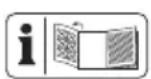
See the fold-out pages for illustrations.
Extent of the delivery
Carefully unpack the appliance and check that it is complete. Dispose of the packaging material correctly.
Device
- 2 cutting disks (pre-mounted)
Vacuum adapter (pre-mounted)
- Reducing adapter for vacuum
- Chuck key
- Hand chisel
- Storage case
- Instructions for use
Functional description
The wall chaser cuts two grooves in brickwork using two parallel diamond cutting disks, without requiring the use of water. Cabling grooves can be opened up by removing the material in between the grooves.
Please refer to the information from the disc manufacturer.
Please refer to the descriptions below for information about the operating devices.
Overview

1 Handgrip
2 On/off switch
3 Switch block
4 Auxiliary handle
5 Maintenance coverage
6 Spindle stop button
7 Cutting disc
8 Start roller
9 Vacuum connector
10 Vacuum adapter
11 Hand chisel
12 Chuck key
13 Rotational direction marking
14 Protective guard opening
15 Mounting spindle
16 Threaded clamping flange
17 Retaining screw

18 Mounting flange
Spacer disks
20 Flange
Technical data
Wall chaser...PMNF 1350 E4
Rated input voltage 230 V\~, 50 Hz
Connected load 1350 W
Idle speed (n) 9000 rpm
Dimension of the
cutting discs 125 x 22,23 mm
Groove depth. 0 - 30 mm
Safety class. II (Double insulation)
Protection category.. .IP X0
Sound pressure level
(L_pA) 94 dB(A); K_pA = 3 dB
Sound power level (L_WA)
measured.....105 dB(A); K_WA = 3 dB
Vibration (q_n) 7,5 m/s2; K= 1,5 m/s2
The vibration values represent maximum values which have been determined with the supplied blade. The actual vibration values may vary depending on the used accessories.
The vibration values are still affected by the handling for the user's.
Cutting disc (included):
ldling speed n_0 max.12250 minDisc speed max.80 m/s* Outer diameter 125 mmBore hole .22,23 mm
- The grinding disc must keep a rotational speed of 80 m/s.
Levels of noise and vibration were determined according to the norms and regulations in the declaration of conformity.
The vibration emission value has been measured according to a standardised testing method and may be used for comparison with another electric tool.
The indicated vibration emission value may also be used for an introductory assessment of the exposure.

Warning:
The vibration emission value whilst actually using the electrical tool may vary from the given values independently of the type and way in which the electric tool is used. Try to keep the exposure to vibrations as low as possible. Examples of measures to reduce vibration exposure are the wearing of gloves when using the tool and limiting the working hours. For this purpose all parts of the operating cycle have to be considered (for example, times when the electric tool is switched off and times when it is switched on but running without any load).
Notes on safety

Caution! When using power tools, observe the following basic safety measures for the prevention of electric shocks and the risk of injury and fire.
Please read all these instructions before using this electric tool and please keep the safety instructions.
Symbols and icons
Symbols on the device:

Warning!

Warning! Electric shock hazard.
Always unplug the device before working on it.

Read the manual!

Wear eye and ear protection.

Wear breathing protection.

Risk of cuts! Wear cut-resistant gloves.

Wear safety shoes.

Do not use for wet grinding.
Working direction

Safety class II (Double insulation).
Electrical machines do not belong with domestic waste.
Other symbols on the cutting disc:

Do not use defective discs.
Symbols used in the instructions:

Hazard symbols with information on prevention of personal injury and property damage.

Hazard symbol with information on the prevention of personal injury caused by electric shock.

Precaution symbol (explanation of precaution instead of exclamation mark) with information on prevention of harm / damage.

Wear ear protection

Switch the device off and remove the mains plug. Allow the device to cool down.

Connect the machine to the power supply.

Wear cut-resistant gloves.
General Safety Directions for Power Tools

WARNING! Read all safety directions and instructions. Omissions in the compliance with safety directions and instructions can cause electrical shock, fire and/or severe injuries.
Retain all safety directions and instructions for future use.
The term "power tool" in the warnings refers to your mains-operated (corded) power tool or battery-operated (cordless) power tool.
1) Work area safety :
a) Keep work area clean and well lit. Cluttered or dark areas invite accidents.
GB E
b) Do not operate power tools in explosive atmospheres, such as in the presence of flammable liquids, gases or dust. Power tools create sparks which may ignite the dust or fumes.
c) Keep children and bystanders away while operating a power tool. Dis- tractions can cause you to lose control.
2) Electrical safety :
a) Power tool plugs must match the outlet. Never modify the plug in any way. Do not use any adapter plugs with earthed (grounded) power tools. Unmodified plugs and matching outlets will reduce risk of electric shock
b) Avoid body contact with earthed or grounded surfaces, such as pipes, radiators, ranges and refrigerators. There is an increased risk of electric shock if your body is earthed or grounded.
c) Do not expose power tools to rain or wet conditions. Water entering a power tool will increase the risk of electric shock.
d) Do not abuse the cord. Never use the cord for carrying, pulling or unplugging the power tool. Keep cord away from heat, oil, sharp edges or moving parts. Damaged or entangled cords increase the risk of electric shock.
e) When operating a power tool outdoors, use an extension cord suitable for outdoor use. Use of a cord suitable for outdoor use reduces the risk of electric shock.
f) If operating a power tool in a damp location is unavoidable, use a RCD (Residual Current Device) protected supply. Use of an RCD reduces the risk of electric shock. Use a circuit breaker with a current limit of 30mA or less.
3) Personal safety:
a) Stay alert, watch what you are doing and use common sense when operating a power tool. Do not use a power tool while you are tired or under the influence of drugs, alcohol or medication. A moment of inattention white operating power tools may result in serious personal injury.
b) Use personal protective equipment. Always wear eye protection. Protective equipment such as dust mask, non-skid safety shoes, hard hat, or hearing protection used for appropriate conditions will reduce personal injuries.
c) Prevent unintentional starting. Ensure the switch is in the off-position before connecting to power source and/or battery pack, picking up or carrying the tool. Carrying power tools with your finger on the switch or energising power tools that have the switch on invites accidents.
d) Remove any adjusting key or wrench before turning the power tool on. A wrench or a key left attached to a rotating part of the power tool may result in personal injury.
e) Do not overreach. Keep proper footing and balance at all times. This enables better control of the power tool in unexpected situations.
f) Dress properly. Do not wear loose clothing or jewellery. Keep your hair, clothing and gloves away from moving parts. Loose clothes, jewellery or long hair can be caught in moving parts.
g) If devices are provided for the connection of dust extraction and collection facilities, ensure these are connected and properly used. Use of dust collection can reduce dust-related hazards.
4) Power tool use and care :
a) Do not force the power tool. Use the correct power tool for your application. The correct power tool will do the job better and safer at the rate for which it was designed.
b) Do not use the power tool if the switch does not turn it on and off. Any power tool that cannot be controlled with the switch is dangerous and must be repaired.
c) Disconnect the plug from the power source and/or the battery pack from the power tool before making any adjust -ments, changing accessories, or storing power tools. Such preventive safety measures reduce the risk of starting the power tool accidentally.
d) Store idle power tools out of the reach of children and do not allow persons unfamiliar with the power
GB E
tool or these instructions to operate the power tool. Power tools are dangerous in the hands of untrained users.
e) Maintain power tools. Check for misalignment or binding of moving parts, breakage of parts and any other condition that may affect the power tool's operation. If damaged, have the power tool repaired before use. Many accidents are caused by poorly maintained power tools.
f) Keep cutting tools sharp and clean. Properly maintained cutting tools with sharp cutting edges are less likely to bind and are easier to control.
g) Use the power tool, accessories and tool bits etc. in accordance with these instructions, taking into account the working conditions and the work to be performed. Use of the power tool for operations different from those intended could result in a hazardous situation.
5) Service:
a) Have your power tool serviced by a qualified repair person using only identical replacement parts. This
will ensure that the safety of the power tool is maintained.
Safety instructions for cutting
a) The protective guard on the device must be securely fastened, and adjusted to ensure maximum safety, i.e. the smallest possible section of the abrasive surface should be visible to the user. Ensure that you and all persons in the vicinity keep out of the plane of the rotating disk. The protective guard is designed to protect users from flying debris and accidental contact with the abrasive surface.
b) Only use diamond cutting disks with this tool. Attaching the accessories to the device does not guarantee safe operation.
c) The allowable rotation speed of the attachment tools must be at least as high as the highest rotation speed indicated on the electric tool. Accessories that run faster than the allowable speed can break and fly apart.
d) Grinding discs may only be used for the recommended applications. For
example: Never sand with the side surface of a cutting disc. Cutting discs are intended for material removal with the edge of the disc. Lateral force on these abrasives can break them.
e) Only use undamaged flanges of the correct size and shape for the grinding disc you have selected. Suitable flanges support the grinding disc and thus reduce the risk of grinding disc breakage.
f) The outside diameter and thickness of the attachment tool must correspond to the dimensions of the power tool. Incorrectly dimensioned attachment tools can not be adequately shielded or controlled.
g) The cutting disks and flanges must fit the grinding spindle precisely. Disks that do not fit the grinding spindle precisely rotate unevenly, vibrate sharply and can lead to loss of control.
h) Never use damaged attachment tools. Check attachment tools such as grinding discs for chipping or cracks, grinding plates for cracks, wear or strong abrasion and wire brushes for loose or
broken wires before using them. If the electric tool or the attachment tool falls off, check whether it is damaged or, use an undamaged attachment tool. If you have checked the attachment tool and attached it, keep yourself and any nearby persons beyond the level of the rotating attachment tool and allow the device to run for 1 min. at the highest rotational speed. Damaged tools usually break during this test period.
i) Wear personal safety equipment. Depending on the application, use full face shields, eye protection or safety goggles. In so far as it is appropriate, wear dust masks, ear protection, gloves or special aprons which keep small grinding and material particles away from you.
Eyes should be protected from the foreign matter which can be caused to fly during the various applications. Dust or breathing masks should filter the dust that is created during operation. If you are exposed to loud noise for a long time, you may suffer hearing loss.
GB E
i) Ensure that other people are at a safe distance to your working area. Anyone who enters the working area should wear personal protective equipment. Broken bits from the piece being worked or broken attachment tools can fly away and cause injuries even beyond the direct working area.
k) Hold the electric tool only by the insulated gripping surfaces when performing work in which the cutting tool may come into contact with hidden wiring or its own cord. Contact with a live wire can also cause a charge in metal parts of the device and result in an electric shock.
1) Keep the cord away from the rotating attachment tool. If you lose control of the device, the power cord can become separated or caught and your hand or arm may be pulled into the rotating attachment tool.
m) Never put the electric tool down before the attachment tool has come to a full stop. The rotating attachment tool can come into contact with the surface upon which it is set, whereby you could lose control of the electric tool.
n) Never allow the electric tool to run while you are carrying it. Your clothing may accidentally come into contact with the rotating attachment tool and get caught and the attachment tool could drill into your body.
o) Clean the ventilation slots of your electric tool routinely. The motor air pulls dust into the housing and, should too much metallic dust collect, could cause electrical hazards.
p) Never use the electric tool near flammable material. Sparks could ignite this material.
q) Do not use attachment tools which require liquid coolant. Using water or another liquid coolant could lead to electrical shock.
Additional safety instructions for all applications
Kickback and corresponding precautions
Kickback is the sudden reaction from a chopping or blocked grinder attachment such as a grinding disc, grinding plate, wire brush etc. Chopping or blocking leads to sudden stopping of the rotating attachment. This causes an uncontrolled electric tool to accelerate in
a direction counter to the rotational direction of the attachment tool. If, for example, a grinding disc cuts into the workpiece or blocks it, the edge of the grinding disc that digs into the workpiece can get caught and, through that, break off the grinding disc or cause a kickback. The grinding disc then moves towards or away from the operator, depending on the direction of rotation of the disc at the blocked spot. Here, the grinding discs can also break. A kickback is caused by wrongly or incorrectly operating the electric tool. It can be avoided by suitable cautionary measures, such as described below.
a) Hold the electric tool very firmly and bring your body and your arm into a position in which you can resist the kickback force. Always use the supplemental handle if available to give you the best control over kickback force or reaction time during acceleration. The operator can master the kickback and reaction force through suitable precautions.
b) Never bring your hands near a rotating attachment tool. The attachment tool can run over your hand in the kickback.
c) Keep your body away from the area in which the electric tool would move during a kickback.
The kickback drives the electric tool in the counter-direction to the rotation of the grinding disc at the blocked spot.
d) Work particularly cautiously in corner areas or where there are sharp corners etc. Prevent the attachment tools from recoiling from the workpiece and jamming. The rotating attachment tool tends to jam when near corners, sharp edges or when it recoils from such. This causes a loss of control or kickback.
e) Do not use chain or toothed saw blades. Such attachment tools frequently cause a kickback or loss of control over the electric tool.
f) Avoid blocking the cutting disc or pressing down too hard. Do not make any excessively deep cuts. Overloading the cutting disc increases wear and its tendency to tilt or block and, with that, to kickback or break the grinder.
g) If the cutting disc jams, or you interrupt your work, switch the device off and hold it until the disc has come to a full stop. Never try to pull the cutting disc out of the cut while it is still running, because it can kick back. Identify and correct the cause of the jamming.
h) Do not switch the electric tool on again as long as it is in the workpiece. Allow the cutting disc to first reach its full rotational speed before you carefully resume with the cutting. Otherwise, the disc may catch, spring away from the workpiece or cause a kickback.
i) Support plates or workpieces to reduce the risk of kickback from a jammed cutting disc. Large workpieces may bend under their own weight. The workpiece must be supported on both sides of the disc, near the cutting disc as well as also at the edge.
j) Be particularly careful for pocket cuts in existing walls or other areas where you cannot see what is there. The cutting disc may cause a kickback when it cuts into gas or water lines, electrical lines or other hidden objects.
Additional safety information
a) Approved cutting disk types: segmented diamond disks with a maximum space of 10mm between segments, only with a negative cutting angle.
Disk diameter: 125 mm
Disk thickness: 2,1 mm
Warning! Always wear ear protection.
RESIDUAL RISKS
Even if properly operating and handling this electric tool, some residual risks will remain. Due to its construction and build, this electric tool may present the following hazards:
a) Lung damage if suitable respiratory protection is not worn.
b) Hearing damage if suitable ear protection is not worn.
c) Damage to health due to touching the area of the grinding tool which is not covered; ejection of parts of workpieces or damaged grinding discs.
d) Health injuries which result from swinging hand and arm, in the event that the device is used over a longer period of time or is not used and maintained properly.
Warning! During operation, this electric tool generates an electromagnetic field which, under certain circumstances, may impair the functionality of active or passive medical implants. To reduce the risk of serious or lethal injuries, we recommend that persons with medical
implants consult their doctor and the manufacturer of their medical implant before operating the machine.
Assembly

Caution! Risk of injury!
insure that you have sufficient space in which to work, and that you do not endanger other people.
-
All hoods and protective devices must be assembled properly before commissioning.
-
Disconnect the mains plug before changing the setting on the device.
Installing/changing disc
-
Press the spindle stop button (6).
-
Turn the mounting spindle (15) until the spindle lock fixed the mounting spindle. Keep and continue to hold down the spindle lock button (6).
-
Release the clamping nut (16) with the chuck key (12). You can release the spindle lock button (6).
-
Remove the threaded clamping flange (16) through the opening in the protective guard (14).
-
Remove the cutting disk (7) by lifting and pulling away the take-up spindle (15) until it reaches the protective guard.
-
Remove the flange (20) and the spacer disks (19) through the opening in the protective guard (14).
-
Remove the second cutting disk (7) as described in point 5.
-
The take-up flange (18) can be left on the take-up spindle (15).
If you remove the take-up flange (18), make sure to position it correctly. The take-up flange's (18) contouring must face towards the motor. If you turn the take-up flange (18), the take-up spindle (15) must turn with it.
-
Position the desired cutting disk (7) on the take-up flange (18).
-
Set the desired cutting width by selecting the spacer disks (19). Push the spacer disks onto the take-up spindle (15). This is followed by the flange (20). This is followed by the second cutting disk (7). All separator disks (19) not used for setting the cutting width must be pushed onto the take-up spindle (15) after the second cutting disk.
-
Reposition the threaded clamping flange (16) on the take-up spindle (15).
-
Press the spindle retaining tab (6), and turn the take-up spindle (15) until the spindle retainer fixes the take-up spindle (15). Retighten the threaded clamping flange (16) using the chuck key (12). You can now release the spindle retaining tab (6).

Information on replacement:
-
Never operate the device without protective equipment.
-
Ensure that the rotation speed stated on the grinding disc (7) is the same or higher than the nominal rotation speed of the device.
-
Ensure that the grinding disc dimensions match those of the device.
Only use flawless grinding discs (ringing test: when you strike the grinding disc with a plastic hammer, it results in a clear sound).
GB E
- Never re-drill a locating hole which is too small to make it larger.
- Never use separate bushings or adapters in order to make grinding discs with a hole that is too large fit the device.
- Do not use any saw blades.

Only replace the diamond cutting disks in pairs.

If the direction of rotation is marked on your cutting disc, make sure that it matches the direction of rotation mark on the tool.

Wear protective gloves when changing the discs in order to avoid cutting damages.
Setting the groove depth
- Release the retaining screw (17).
- Set the scale on the protective cover (5) to the required depth.
- Reattach the protective guard (5) with the retaining screw (17).
Vacuuming
During operation, the wall chaser generates a large quantity of dust. You should therefore wear a dust mask, and always connect an industrial vacuum cleaner.
If the vacuum system malfunctions, pause operation and clear the malfunction!
Attaching the vacuum cleaner
Unscrew the suction connector (9) cap. Insert the industrial vacuum cleaner's hose through the cap and screw the cap tight.
If your vacuum cleaner's hose is the wrong diameter for a direct connection, you can insert the vacuum adapter (10) in between with a single turn.
Always attach a vacuum cleaner. Damage to the motor caused by failure to attach a vacuum cleaner is not covered by the warranty.
Operation
Caution! Risk of injury! Always remove the mains plug before working on the tool
Only use diamond cutting discs and accessories recommended by the manufacturer. Using other attachment tools and other accessories can represent a risk of injury for you.
Only use grinding tools which bear information about the manufacturer, type of binding, dimension and permitted number of revolutions.
- Only use grinding discs where the printed rotational speed is at least as high as what has been specified on the name plate of the device.
- -Do not use any broken, cracked or otherwise damaged diamond cutting discs
- Never operate the device without protective equipment.
Support the plates or workpieces in order to reduce the risk of kickback from a jammed cutting disc. Large workpieces may bend under their own weight. The workpiece must be supported on both sides of the disc, not only near the cutting disc, but also at the edge.

Keep your hands away from the disc when the device is in operation. Risk of injury.

Switch the device off and remove the mains plug. Allow the device to cool down.
Notes on statics:
Slots in load-bearing walls are subject to the standard DIN 1053 Part 1 or country-specific specifications. These rules must be strictly adhered to. Before starting work, consult the responsible structural engineer, architect or the responsible construction management.
Turning on and off

Make sure that the power supply voltage matches the voltage rating indicated on the device's type plate.

Connect the machine to the power supply.
- To start the device, push the switch lock (3) forwards. Press the on/off switch (2).
- To turn it off, release the on-off button. The device turns off.
After switching on the device, wait until the device has reached its max. speed. Only then should you start with the work.

The disc still runs even after the device has been switched off. Risk of injury.
Trial run:
Always carry out a trial run before carrying out your first grinding procedure and after every disc replacement. Switch the device off immediately if the diamond cutting disc is not rotating smoothly, if considerable vibration occurs or if you hear abnormal noises.
Handling

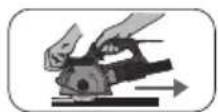
Using a line locator, check the walls for hidden electricity cabling and gas and water pipes before working with the wall chaser.
- Switch on the wall chaser, position the start roller (8) against the wall while the cutting disks are rotating.
- Bring the cutting disks into contact with the wall.
- The cutting direction should always be opposite to the disks' rotational direction. Check the marking (13). Pull the machine towards you when working. Otherwise, the wall chaser can be pushed outside the cutting area in an uncontrolled manner.
- Once you reach the end of the groove, remove the device from the groove before switching it off.
- Chip out the resulting ridge between the two grooves using the hand chisel (11).
Cleaning and servicing

Pull the mains plug before any adjustments, maintenance or repair.
Maintenance

Have any work on the device that is not described in this instruction guide performed by a professional. Only use original parts. Allow the device to cool off before any maintenance or cleaning is undertaken. There is a risk of burning!
Always check the device before using it for obvious deficiencies such as loose, worn or damaged parts, correct the positioning of screws or other parts. Check the diamond cutting disc in particular. Exchange the damaged parts.
If the replacement of the supply cord is necessary, this has to be done by the manufacturer or his agent in order to avoid a safety hazard.
Cleaning

Do not use any cleaning agent or solvent. Chemical substances can etch the plastic parts of the device. Never clean the device under running water.
- Thoroughly clean the device after every use.
- Clean the ventilation openings and the surface of the device with a soft brush or cloth.
Storage
- Store the appliance in a dry place well out of reach of children.
- Diamond cutting discs must be dry and stored upright and should never be stacked.
Waste disposal and environmental protection
Be environmentally friendly. Return the tool, accessories and packaging to a recycling centre when you have finished with them.
Electrical machines do not belong with domestic waste.
- Hand over the device at an utilization location. The plastic and metal parts employed can be separated out and thus recycled use can be implemented. Ask our Service-Center for details.
Defective units returned to us will be disposed of for free.
Replacement parts / Accessories
Spare parts and accessories can be obtained at www.grizzlytools-service.eu
If you have issues ordering, please use the contact form.
If you have any other questions, contact the "Service-Center" (see page 42).
Item Description Order No.
| A7 | Cutting discs (2) | 30211073 |
| A10 | Vacuum adapter 91104226 | |
| A9 | Vacuum connector 91104735 | |
| A16 | Threaded clamping flange, Mounting flange, | 91104736 |
| B18,19,20 | Spacer disks, Flange | |
| A11 | Hand chisel 91104737 | |
| A12 | Chuck key | 91104738 |
Troubleshooting

Always unplug the shredder before working on it.
Risk of electric shock!
| Problems Possible Cause Error correction | ||
| Device doesn't start | Mains voltage missingMain circuit breaker is tripped | Check the socket, mains cable, line,mains plug, repairs to be carried out by qualified electrician if neces-sary, check main circuit breaker. |
| On/off switch (A 2) may be defective | Repair by Customer Care | |
| Engine faulty | ||
| Grinding tool does not move al-though the engine is runningt | Threaded clamping flange (A 16) is loose | Tighten threaded clamping flange (16) (see „Changing disc") |
| Workpiece, remaining work-pieces block drive | Remove blockages | |
| Engine is slower and stops | Device is overloaded through workpiece | Reduce pressure on cutting tool |
| Workpiece unsuitable | ||
| Grinding disc does not rotate smoothly, abnor-mal noises can be heard | Threaded clamping flange (A 16) is loose | Tighten threaded clamping flange (16) (see „Changing disc") |
| Cutting discs are defective Change cutting discs | ||
Guarantee
Dear Customer,
This equipment is provided with a 3-year guarantee from the date of purchase.
In case of defects, you have statutory rights against the seller of the product. These statutory rights are not restricted by our guarantee presented below.
Terms of Guarantee
The term of the guarantee begins on the date of purchase. Please retain the original receipt. This document is required as proof of purchase.
If a material or manufacturing defect occurs within three years of the date of purchase of this product, we will repair or replace - at our choice - the product for you free of charge. This guarantee requires the defective equipment and proof of purchase to be presented within the three-year period with a brief written description of what constitutes the defect and when it occurred.
If the defect is covered by our guarantee, you will receive either the repaired product or a new product. No new guarantee period begins on repair or replacement of the product.
Guarantee Period and Statutory Claims for Defects
The guarantee period is not extended by the guarantee service. This also applies for replaced or repaired parts. Any damages and defects already present at the time of purchase must be reported immediately after unpacking. Repairs arising after expiry of the guarantee period are chargeable.
Guarantee Cover
The equipment has been carefully produced in accordance with strict quality guidelines and conscientiously checked prior to delivery.
The guarantee applies for all material and manufacturing defects. This guarantee does not extend to cover product parts that are subject to normal wear and may therefore be considered as wearing parts (e.g. Diamond cutting disc, the clamping flanges) or to cover damage to breakable parts (e.g. switches).
This guarantee shall be invalid if the product has been damaged, used incorrectly or not maintained. Precise adherence to all of the instructions specified in the operating manual is required for proper use of the product. Intended uses and actions against which the operating manual advises or warns must be categorically avoided.
The product is designed only for private and not commercial use. The guarantee will be invalidated in case of misuse or improper handling, use of force, or interventions not undertaken by our authorised service branch.
Processing in Case of Guarantee
To ensure efficient handling of your query, please follow the directions below:
- Please have the receipt and item number (IAN 356345_2004) ready as proof of purchase for all enquiries.
- Please find the item number on the rating plate.
- Should functional errors or other defects occur, please initially contact the service department specified below by telephone or by e-mail. You will then receive further information on the processing of your complaint.
GB E
- After consultation with our customer service, a product recorded as defective can be sent postage paid to the service address communicated to you, with the proof of purchase (receipt) and specification of what constitutes the defect and when it occurred. In order to avoid acceptance problems and additional costs, please be sure to use only the address communicated to you. Ensure that the consignment is not sent carriage forward or by bulky goods, express or other special freight. Please send the equipment inc. all accessories supplied at the time of purchase and ensure adequate, safe transport packaging.
Repair Service
For a charge, repairs not covered by the guarantee can be carried out by our service branch, which will be happy to issue a cost estimate for you. We can handle only equipment that has been sent with adequate packaging and postage.
Attention: Please send your equipment to our service branch in clean condition and with an indication of the defect.
Equipment sent carriage forward or by bulky goods, express or other special freight will not be accepted.
We will dispose of your defective devices free of charge when you send them to us.
Service-Center
GB Service Great Britain Tel.:08004047657 E-Mail:grizzly@lidl.co.uk IAN 356345_2004
IE Service Ireland Tel.:1890 930 034 (0,08 EUR/Min.,(peak)) (0,06 EUR/Min.,off peak)) E-Mail:grizzly@lidl.ie IAN 356345_2004
Importer
Please note that the following address is not a service address. Please initially contact the service centre specified above.
Garantie - France. 63
Chere cliente, cher client,
| GB IE | Translation of the original EC declaration of conformity |
| We hereby confirm that the Wall chaser Design Series PMNF 1350 E4 Serial Number 000001 - 041050 conforms with the following applicable relevant version of the EU guidelines : | |
| 2006/42/EC • 2014/30/EU • 2011/65/EU* • (EU) 2015/863 | |
| In order to guarantee consistency, the following harmonised standards as well as national standards and stipulations have been applied: | |
| EN 60745-1:2009/A11:2010 • EN 60745-2-22:2011/A11:2013 EN 55014-1:2017 • EN 55014-2:2015 • EN IEC 63000:2018 EN 61000-3-2:2014 • EN 61000-3-3:2013 • EN 13236:2019 | |
| This declaration of conformity is issued under the sole responsibility of the manufacturer: | |
| CE Grizzly Tools GmbH & Co. KG Stockstädter Straße 20 63762 Großbostheim Germany 30.10.2020 | Christian Frank Documentation Representative |
- The object of the declaration described above satisfies the provisions of Directive 2011/65/EU of the European Parliament and the Council of 8 June 2011 on limiting the use of certain harmful substances in electrical and electronic appliances.


- Mauernutfrase / Wall Chaser / Rainureuse PMNF 1350 E4
- Mauernutfräse
- Muurgroeff rees
- FR B
- Introduction
- Intended purpose
- General description
- Extent of the delivery
- Functional description
- Overview
- Technical data
- Wall chaser...PMNF 1350 E4
- Cutting disc (included):
- Warning:
- Notes on safety
- Symbols and icons
- Symbols on the device:
- Other symbols on the cutting disc:
- Symbols used in the instructions:
- General Safety Directions for Power Tools
- Retain all safety directions and instructions for future use.
- 1) Work area safety :
- GB E
- 5) Service:
- Safety instructions for cutting
- Additional safety instructions for all applications
- Kickback and corresponding precautions
- Additional safety information
- Warning! Always wear ear protection.
- RESIDUAL RISKS
- Assembly
- Caution! Risk of injury!
- Installing/changing disc
- Information on replacement:
- Only replace the diamond cutting disks in pairs.
- Setting the groove depth
- Vacuuming
- Attaching the vacuum cleaner
- Operation
- Caution! Risk of injury! Always remove the mains plug before working on the tool
- Keep your hands away from the disc when the device is in operation. Risk of injury.
- Notes on statics:
- Turning on and off
- Trial run:
- Handling
- Using a line locator, check the walls for hidden electricity cabling and gas and water pipes before working with the wall chaser.
- Cleaning and servicing
- Maintenance
- Cleaning
- Storage
- Waste disposal and environmental protection
- Replacement parts / Accessories
- Spare parts and accessories can be obtained at www.grizzlytools-service.eu
- Troubleshooting
- Guarantee
- Terms of Guarantee
- Guarantee Period and Statutory Claims for Defects
- Guarantee Cover
- Processing in Case of Guarantee
- Repair Service
- Service-Center
- Importer
Brand : PARKSIDE
Model : PMNF 1350 E4
Category : Milling machine