
Omada EAP615Wall - Access Point TP-LINK - Free user manual and instructions
Find the device manual for free Omada EAP615Wall TP-LINK in PDF.
| Product Type | Wi-Fi 6 Wall Access Point |
| Brand | TP-Link |
| Model | Omada EAP615Wall |
| Wi-Fi Standard | IEEE 802.11ax/ac/n/g/b/a |
| Frequency Bands | 2.4 GHz and 5 GHz |
| Max Speed (2.4 GHz) | 574 Mbps |
| Max Speed (5 GHz) | 1201 Mbps |
| Number of Antennas | 2 internal |
| Ports | 1 Gigabit Ethernet port (PoE) |
| Power Supply | PoE 802.3af |
| Power Consumption | ~9 W |
| Dimensions | 86 x 86 x 33.5 mm |
| Weight | 150 g |
| Mounting | Wall (flush) or ceiling |
| Operating Temperature | 0°C to 40°C |
| Operating Humidity | 10% to 90% non-condensing |
| Advanced Features | MU-MIMO, OFDMA, Beamforming, BSS Coloring |
| Security | WPA3, WPA2, WPA, 802.1X, Rogue AP Detection |
| Management | Omada Controller, web app, cloud |
| Certifications | CE, FCC |
| Warranty | 3 years |
| Maintenance and Cleaning | Clean with a dry cloth. Do not use liquid or abrasive cleaners. |
| Spare Parts and Repairability | No detachable parts. For repair, contact customer service. |
Frequently Asked Questions - Omada EAP615Wall TP-LINK
User questions about Omada EAP615Wall TP-LINK
0 question about this device. Answer the ones you know or ask your own.
Ask a new question about this device
Download the instructions for your Access Point in PDF format for free! Find your manual Omada EAP615Wall - TP-LINK and take your electronic device back in hand. On this page are published all the documents necessary for the use of your device. Omada EAP615Wall by TP-LINK.
USER MANUAL Omada EAP615Wall TP-LINK
Hardwareinstallation
■ Option 1: Deckenmontage
natural_image
Diagram showing a grid of empty rectangular cells with one cell highlighted by a downward arrow (no text or symbols present)natural_image
Pure mechanical diagram showing a rotating component with springs and pulleys, no text or symbols presentnatural_image
Simple line drawing of a clock face inside a rectangular frame (no text or symbols)natural_image
Diagram of a circular object with rotational arrows, no text or symbols present■ Option 2: Wandmontage
natural_image
Diagram showing a hand holding a small object with a magnified inset, no text or symbols presentnatural_image
Pure electrical circuit lines without any symbolsnatural_image
Technical diagram showing a mechanical assembly with two parallel plates and a textured panel (no text or symbols)Note: Images may differ from your actual product
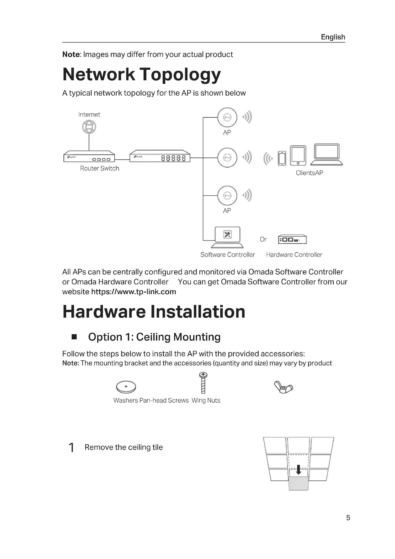
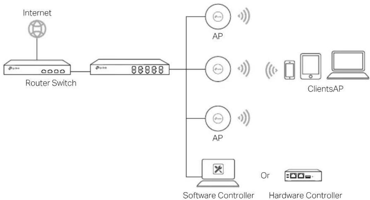
Network Topology
A typical network topology for the AP is shown below
flowchart
graph LR
    A["Internet"] --> B["Router Switch"]
    B --> C["AP"]
    B --> D["AP"]
    B --> E["AP"]
    C --> F["Software Controller"]
    D --> F
    E --> G["Hardware Controller"]
    H["ClientsAP"] --> I["Smartphone"]
    H --> J["Laptop"]
    H --> K["Computer"]
All APs can be centrally configured and monitored via Omada Software Controller or Omada Hardware Controller You can get Omada Software Controller from our website https://www.tp-link.com
Hardware Installation
■ Option 1: Ceiling Mounting
Follow the steps below to install the AP with the provided accessories:
Note: The mounting bracket and the accessories (quantity and size) may vary by product

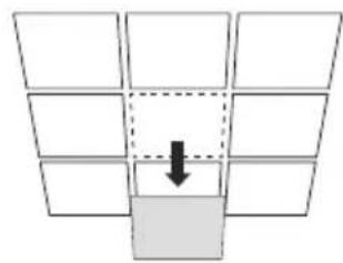
1 Remove the ceiling tile
natural_image
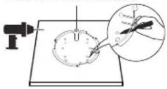
Diagram showing a grid of 10 squares with one square highlighted by a downward arrow (no text or symbols)2 Place the mounting bracket in the center of the ceiling tile Mark positions for the screw holes and a position for the Ethernet cable hole Drill 4 mm diameter holes for the screws and a 25 mm diameter hole for the Ethernet cable at the marked positions
Hole for Ethernet cable
natural_image
Diagram showing a tool interacting with a spherical object, with an inset magnified view of a hand holding a small object (no text or symbols present)3 Secure the mounting bracket to the ceiling tile using pan-head screws, washers and wing nuts
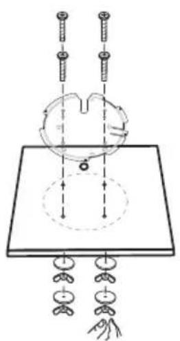
natural_image
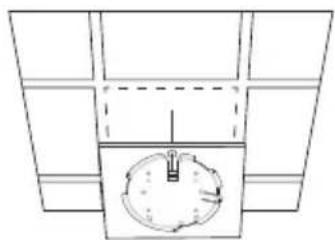
Diagram of a mechanical or electrical setup with two vertical rods and a central circular component, connected to hanging weights (no text or symbols present)4 Feed the Ethernet cable through the hole and set the ceiling tile back into place
natural_image
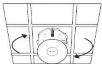
Top-down architectural diagram of a circular object mounted on a truss structure (no text or symbols)5 Connect the Ethernet cable to the Ethernet port Attach the AP to the mounting bracket by aligning the arrow mark on the AP with the arrow mark on the mounting bracket, then rotate the AP until it is locked into place
natural_image
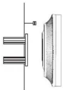
Diagram of a mechanical or electrical component with directional arrows indicating rotation, no text or symbols present.■ Option 2: Wall Mounting
Follow the steps below to install the AP with the provided accessories: Note: The mounting bracket and the accessories (quantity and size) may vary by product
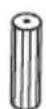
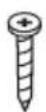
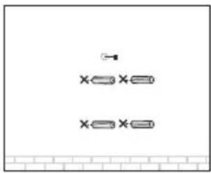
Plastic Wall Anchors Self-tapping Screws
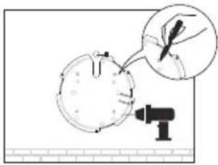
1 If your Ethernet cable feeds through the wall, position the mounting bracket and feed the Ethernet cable Mark positions for the screw holes and then drill 6 mm diameter holes at the marked positions
2 Insert the plastic wall anchors into the 6 mm diameter holes
natural_image
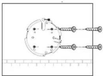
Pure electrical circuit lines without any symbols3 Secure the mounting bracket to the wall by driving the self-tapping screws into the anchors Make sure that the shoulders of the mounting bracket are on the outside
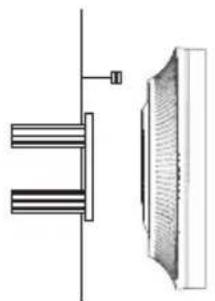
4 Connect the Ethernet cable to the Ethernet port on the AP

natural_image
Technical diagram showing a mechanical assembly with two parallel plates and a textured panel (no text or symbols)5 Attach the AP to the mounting bracket by aligning the arrow mark on the AP with the arrow mark on the mounting bracket, then rotate the AP until it is locked into place
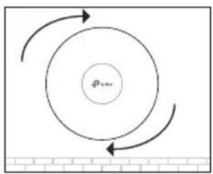
flowchart
graph TD
    A["Outer Ring"] --> B["Inner Ring"]
    B --> C["Center Point p..."]
    C --> A
    style A fill:#f9f,stroke:#333
    style B fill:#ccf,stroke:#333
    style C fill:#cfc,stroke:#333
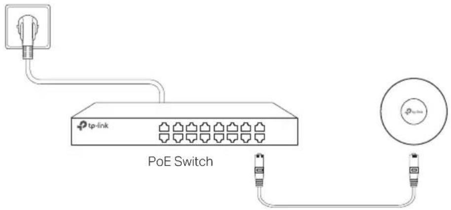
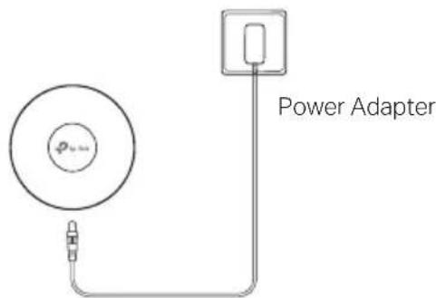
Power Supply
■ Power via PSE Device or Power Adapter
Some APs can be powered via the power adapter or the PSE device (such as a PoE switch) which complies with Power Source Class 2 (PS2) or Limited Power Source (LPS) of IEC 62368-1
Note: Availability depends on the actual product Please refer to the product specifications
Via PoE Switch
Via Power Adapter
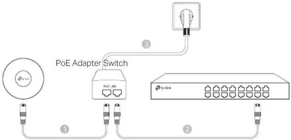
■ Power via PoE Adapter
Some APs can be powered via the PoE adapter
Note: Availability depends on the actual product Please refer to the product specifications
flowchart
graph TD
    A["Power Hub"] --> B["PoE Adapter Switch"]
    B --> C["Router"]
    C --> D["1"]
    C --> E["2"]
    C --> F["3"]
    G["Light Bulb"] --> H["Switch"]
    style A fill:#f9f,stroke:#333
    style G fill:#ccf,stroke:#333
    style B fill:#cfc,stroke:#333
    style C fill:#fcc,stroke:#333
    style D fill:#cff,stroke:#333
    style E fill:#ffc,stroke:#333
    style F fill:#cfc,stroke:#333
natural_image
Diagram showing a grid of empty rectangular cells with one cell highlighted by a downward arrow (no text or symbols present)natural_image
Diagram of a mechanical setup with springs and a central rotating component (no text or symbols)natural_image
Top-down schematic of a mechanical or electrical component with no visible text, numbers, or symbolsnatural_image
Diagram of a circular device with directional arrows indicating rotation or movement (no text or symbols)natural_image
Pure electrical circuit lines without any symbols4 Conecte el cable Ethernet al puerto ETHERNET en el AP

natural_image
Technical diagram showing a mechanical assembly with two parallel plates and a textured panel (no text or symbols)natural_image
Three technical line drawings of mechanical parts: a circular base, a threaded bolt, and a curved bracket (no text or symbols)natural_image
Diagram showing a grid of 10 squares with one square highlighted by a black arrow (no text or symbols)natural_image
Diagram of a mechanical setup with pulleys, weights, and a central rotating component (no text or labels)natural_image
Simple line drawing of a clock face with no text or symbolsnatural_image
Diagram of a circular object with directional arrows indicating rotation or movement, surrounded by grid panels (no text or symbols)natural_image
Diagram showing a hand holding a small object with a magnified inset, no text or symbols presentnatural_image
Pure electrical circuit lines without any symbolsnatural_image
Technical diagram showing a mechanical assembly with two parallel plates and a textured panel (no text or symbols)natural_image
Diagram showing a grid of 10 empty squares with one square highlighted by a downward arrow (no text or symbols)natural_image
Diagram of a robotic arm with sensors and motion lines, no text or symbols presentnatural_image
Top-down diagram of a room with furniture and a central circular object (no text or symbols)natural_image
Diagram of a circular component with directional arrows indicating rotation, surrounded by grid panels (no text or symbols)natural_image
Simple diagram with three horizontal lines and a small arrow, no text or symbols presentnatural_image
Technical diagram showing a mechanical assembly with two parallel plates and a textured panel (no text or symbols)flowchart
graph TD
    A["Outer Circle"] --> B["Inner Circle"]
    B --> C["Outer Circle"]
    C --> D["Inner Circle"]
    D --> E["Outer Circle"]
    E --> F["Outer Circle"]
    F --> G["Outer Circle"]
    G --> H["Outer Circle"]
    H --> I["Outer Circle"]
    I --> J["Outer Circle"]
    J --> K["Outer Circle"]
    K --> L["Outer Circle"]
    L --> M["Outer Circle"]
    M --> N["Outer Circle"]
    N --> O["Outer Circle"]
    O --> P["Outer Circle"]
    P --> Q["Outer Circle"]
    Q --> R["Outer Circle"]
    R --> S["Outer Circle"]
    S --> T["Outer Circle"]
    T --> U["Outer Circle"]
    U --> V["Outer Circle"]
    V --> W["Outer Circle"]
    W --> X["Outer Circle"]
    X --> Y["Outer Circle"]
Alimentation
natural_image
Diagram showing a grid of empty rectangular cells with a downward arrow pointing to a shaded bottom layer (no text or symbols)natural_image
Illustration of a tool interacting with a circular object on a flat surface, with an inset showing a hand holding a tool (no text or symbols present)natural_image
Diagram of a mechanical setup with pulleys, weights, and a central gear mechanism (no text or labels)natural_image
Simple line drawing of a clock inside a rectangular frame (no text or symbols)natural_image
Diagram of a circular object with arrows indicating rotational motion, no text or symbols presentnatural_image
Diagram showing a hand holding a small object with a magnified inset, no text or symbols presentnatural_image
Pure electrical circuit lines without any symbolsnatural_image
Technical diagram showing a mechanical assembly with two parallel plates and a textured panel (no text or symbols)natural_image
Three technical line drawings of mechanical components: a circular plate, a threaded screw with a plus sign, and a curved pipe fitting (no text or symbols)natural_image
Diagram showing a grid of 10 cells with one cell highlighted by a black arrow (no text or symbols present)natural_image
Diagram of a mechanical or electrical setup with two screws and a central circular component, no visible text or symbolsnatural_image
Top-down schematic of a mechanical or electrical component with no visible text, numbers, or symbolsnatural_image
Diagram of a circular device with directional arrows indicating rotation or movement (no text or symbols)natural_image
Simple diagram with three horizontal lines and a small arrow, no text or symbols present4 Conecte o cabo de rede Ethernet na porta de rede Ethernet
natural_image
Technical line drawing of a mechanical assembly with two parallel plates and a textured wall (no text or symbols)natural_image
Diagram showing a grid of 10 empty squares with one highlighted by a downward arrow (no text or symbols)natural_image
Diagram showing a tool interacting with a circular object on a base, with an inset magnified view of the tool interacting (no text or symbols present)natural_image
Diagram of a mechanical or scientific setup with two vertical rods and a central circular component, connected by hanging weights (no text or symbols present)natural_image
Simple line drawing of a circular object placed on a rectangular base, with no text or symbols present.natural_image
Diagram of a circular component with directional arrows indicating rotation or movement, surrounded by grid panels (no text or symbols)natural_image
Diagram showing a hand holding a small object with a magnified inset, no text or symbols presentnatural_image
Pure electrical circuit lines without any symbolsnatural_image
Technical diagram showing a mechanical assembly with two parallel plates and a textured panel (no text or symbols)natural_image
Diagram showing a grid of 10 empty squares with one highlighted in a dashed box and a black arrow pointing downward (no text or symbols)natural_image
Diagram of a mechanical or electrical setup with springs and a central rotating component, no visible text or symbolsnatural_image
Top-down schematic of a room layout with numbered compartments and a central circular object (no text or symbols)natural_image
Diagram of a mechanical component with rotational arrows indicating motion, no text or symbols present■ Optie 2: Plafondmontage
natural_image
Diagram showing a hand holding a small object with a magnified inset, no text or symbols presentnatural_image
Pure electrical circuit lines without any symbolsnatural_image
Technical diagram showing a mechanical assembly with two parallel plates and a textured panel (no text or symbols)natural_image
Diagram showing a 3x3 grid with a downward arrow pointing to a shaded rectangular area (no text or symbols)natural_image
Diagram of a robotic arm with sensors and motion indicators, no text or symbols presentnatural_image
Simple line drawing of a clock with a pointer, no text or symbols presentnatural_image
Diagram of a mechanical component with rotational arrows indicating motion, no text or symbols presentnatural_image
Diagram showing a hand holding a small object with a magnified inset, no text or symbols presentnatural_image
Pure electrical circuit lines without any symbolsnatural_image
Technical diagram showing a mechanical assembly with two parallel plates and a textured panel (no text or symbols)■ Ström via PoE-adapter
Vissa AP:er kan drivas via PoE-adaptern
natural_image
Diagram showing a grid of empty squares with one highlighted by a black arrow, no text or symbols present.natural_image
Diagram of a mechanical or electrical setup with two vertical rods and a central circular component, connected to hanging weights (no text or symbols present)natural_image
Top-down architectural diagram of a room with furniture layout and central circular object (no text or symbols)natural_image
Diagram of a circular device with directional arrows indicating rotation or movement (no text or symbols)■ Alternativ 2: Montering på vegg
natural_image
Diagram showing a hand holding a small object with a magnified inset, no text or symbols presentnatural_image
Pure electrical circuit lines without any symbols4 Koble Ethernet-kabelen til Ethernet-porten på AP
natural_image
Technical diagram showing a mechanical assembly with two parallel plates and a textured panel (no text or symbols)■ Strøm via PoE-adapter
Noen AP-er kan drives via PoE-adapteren
natural_image
Diagram showing a grid of empty rectangular cells with one cell highlighted by a downward arrow (no text or symbols present)natural_image
Diagram of a mechanical or electrical setup with two vertical rods, a central circular component, and hanging weights on a base (no text or symbols)natural_image
Simple line drawing of a clock face with no text or symbolsnatural_image
Diagram of a mechanical or electrical component with circular head and rotating arrows, no text or symbols presentnatural_image
Pure electrical circuit lines without any symbols4 Forbind Ethernet-kablet til ETHERNET-porten på AP

natural_image
Technical diagram showing a mechanical assembly with two parallel plates and a textured panel (no text or symbols)■ Strøm via PoE-adapter
Nogle AP'er kan forsynes med strøm via PoE-adapteren
- Keep the device away from water, fire, humidity or hot environments
- Do not attempt to disassemble, repair, or modify the device If you need service, please contact us
- Do not use damaged charger or USB cable to charge the device
- Do not use any other chargers than those recommended
- Do not use the device where wireless devices are not allowed
- Adapter shall be installed near the equipment and shall be easily accessible
Please read and follow the above safety information when operating the device We cannot guarantee that no accidents or damage will occur due to improper use of device Please use this product with care and operate at your own risk
Español
TP-Link hereby declares that the device is in compliance with the essential requirements and other relevant provisions of directives (EU)2015/863, 2014/53/EU, 2009/125/EC and 2011/65/EU
The original EU declaration of conformity may be found at https://www.tp-link.com/en/support/ce/
Español
https://www.tp-link.com/en/support/ce/
Nederlands
https://www.tp-link.com/de/support
For TP-Link Branded Products Only For the information about warranty period, policy and procedures, please visit https://www.tp-link.com/en/support THIS WARRANTY GIVES YOU SPECIFIC LEGAL RIGHTS, AND YOU MAY HAVE OTHER RIGHTS THAT VARY FROM STATE TO STATE (OR BY COUNTRY OR PROVINCE)
TO THE EXTENT ALLOWED BY LOCAL LAW, THIS WARRANTY AND THE REMEDIES SET FORTH ARE EXCLUSIVE AND IN LIEU OF ALL OTHER WARRANTIES, REMEDIES AND CONDITIONS
TP-Link warrants the TP-Link branded hardware product contained in the original packaging against defects in materials and workmanship when used normally in according with TP-Link's guidelines for some period which depends on the local service from the date of original retail purchase by the end-user purchaser
Español
https://www.tp-link.com/gr/support
For technical support, the user guide and other information, please visit https://www tp-link com/support/, or simply scan the QR code.