SCCJ60S - Food warmer Vevor - Free user manual and instructions
Find the device manual for free SCCJ60S Vevor in PDF.

User questions about SCCJ60S Vevor
0 question about this device. Answer the ones you know or ask your own.
Ask a new question about this device
Download the instructions for your Food warmer in PDF format for free! Find your manual SCCJ60S - Vevor and take your electronic device back in hand. On this page are published all the documents necessary for the use of your device. SCCJ60S by Vevor.
USER MANUAL SCCJ60S Vevor
Technical Support and E-Warranty Certificate www.vevor.com/support
Food Warmer Display
Model:SC-CJ-60S/SC-CJ-601/
SC-CJ-602/SC-CJ-603
We continue to be committed to provide you tools with competitive price. "Save Half", "Half Price" or any other similar expressions used by us only represent the estimate of savings you might benefit from buying certain tools with us compared to top brands and does not necessarily mean to cover all categories of tools offered. Are kindly reminded to verify carefully when you are placing an order with us actually saving half in comparison with the top major brands.
MODEL:SC-CJ-60S/SC-CJ-601/SC-CJ-602/SC-CJ-603
SC-CJ60S
SC-CJ-601
SC-CJ-602
SC-CJ-603
? CONTACT US!
Have product questions? Need technical support? Please feel fr contact us:
Technical Support and E-Warranty Certificate www.vevor.com/support
This is the original instruction, please read all manual instruction carefully before operating. VEVOR reserves a clear interpretation user manual. The appearance of the product shall be subject to product you received. Please forgive us that we won't inform you there are any technology or software updates on our product.
| Warning-To reduce the risk of injury, user must re instructions manual carefully. | |
| CORRECT DISPOSAL This product is subject to the provision of European D 2012/19/EU. The symbol showing a wheelie bin cros through indicates that the product requires separate recollection in the European Union. This applies to the and all accessories marked with this symbol. Products as such may not be discarded with normal domestic w must be taken to a collection point for recycling elec electronic devices. | |
| Indoor Use Only |

Warm reminder
To ensure that this product will not be scratched during transportation protective film is attached to the surface of the machine. Please tear protective films before use!
1. Instructions for use:
- The product must be safely grounded before use!
- The voltage used by the product must be consistent with the rated voltage.
- During each use, add water to the water basin to 2/3 of the cap before turning on the power.
-
Turn on the power, the power indicator light is on, turn the temper control heating switch, and select the insulation temperature of the foci increase the temperature of the space inside the cabinet. Through national convection, the temperature of each layer can be kept consistent.
-
During use, if you need lighting, you can turn on the lighting switch light group, and all lights will be turned on, which can improve the effect.
- After use, the power must be cut off when cleaning to prevent ac
- If any abnormality occurs during use, stop using it and ask a professional to troubleshoot it before continuing to use it.
This product is not intended for use by persons (including children) who are reduced physical, sensory, or mental capabilities or lack of experience in knowledge.
- Since the temperature of the equipment is relatively high during operation, do not bring your hands or other parts of the body close surface of the machine to avoid burns or other injuries.
2. Precautions and maintenance:
- It should be operated by designated personnel and should be prof in the use of machinery and equipment.
- Be careful when moving the machine. If there is a fault, it must repaired by a professional. Do not knock it.
- Please do not install and store this equipment in the following locations to avoid malfunction due to misoperation:
3.1 On an unstable table or counter.
3.2 Places where the temperature is too high or too low.
3.3 Places with excessive air volume and excessive dust.
3.4 Places where the power supply voltage is very unstable.
3.5 Where there is no good grounding device. - The appliance must not be cleaned with a water spray pipe or in in water to prevent electrical leakage.
- It is strictly prohibited to use liquids that are soluble in baking paper wipe the surface of the insulation cabinet.
- Special precautions:
6.1 This product is a commercial device and is not suitable for home
6.2 It cannot be disassembled or modified. Disassembling it without permission may cause serious accidents.
6.3 The power needs to be cut off before cleaning to preventAccide leakage accidents.
6.4 It is prohibited to use hard or sharp objects to scratch the glass
3. Normal working environment conditions:
- The ambient temperature is 5 - 50^ , and the relative air humidity is more than 90% ;
- Power supply voltage: 110V± 10% , frequency: 60± 1% HZ . (220V±10%, frequency: 50± 1% )
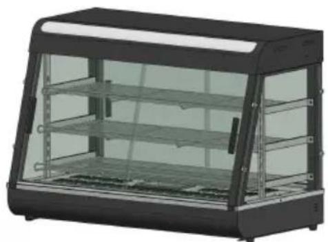
4. Product introduction:
- This product has a novel and unique design, arc shape, multi-layer adjustable grid shelf, four-sided glass perspective, the top uses an environmentally friendly high-transparency PC board as a light-transmitting light panel, and a white LED tube is used internally to increase the life; users can Put different advertising cards according to your own preferences to increase the beauty. The convenient disassembly and assembly structure is easy to operate, sturdy and durable, and easy maintain. It has an optional constant temperature and a temperature display. The top warm tube downlight design can make the light more uniform, and it is equipped with moisturizing compensation to keep the food fresh. It is a special equipment for food display and heat pres
5. Symbol description:
In this manual, symbols are used to highlight all important safety instructions and recommendations related to the equipment. To avoid the risk of accidents, personal injury, or property damage, follow these instructions with special care.
- Model, specifications and main technical parameters:
| Model | Voltage(V) | Power(KW) | Frequency(HZ) | Temperaturerange | Dimension(MM) |
| SC-CJ-60S | AC110-120 | 1 | 60 | 86-185F | 385*490*640 |
| AC220-240 | 50 | 30-85°C | |||
| SC-CJ-601 | AC110-120 | 1.2 | 60 | 86-185F | 667*470*640 |
| AC220-240 | 50 | 30-85°C | |||
| SC-CJ-602 | AC110-120 | 1.5 | 60 | 86-185F | 907*470*640 |
| AC220-240 | 50 | 30-85°C | |||
| SC-CJ-603 | AC110-120 | 1.5 | 60 | 86-185F | 1210*470*640 |
| AC220-240 | 50 | 30-85°C |
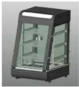
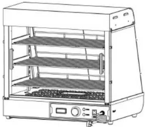
7. Product appearance picture
SC-CJ-60S
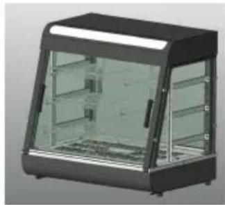
SC-CJ-601
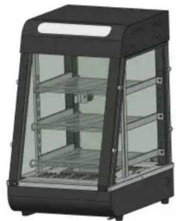
SC-CJ-602
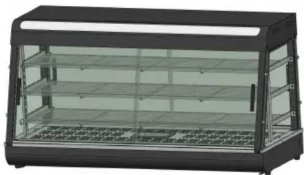
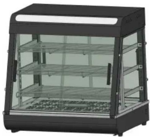
SC-CJ603
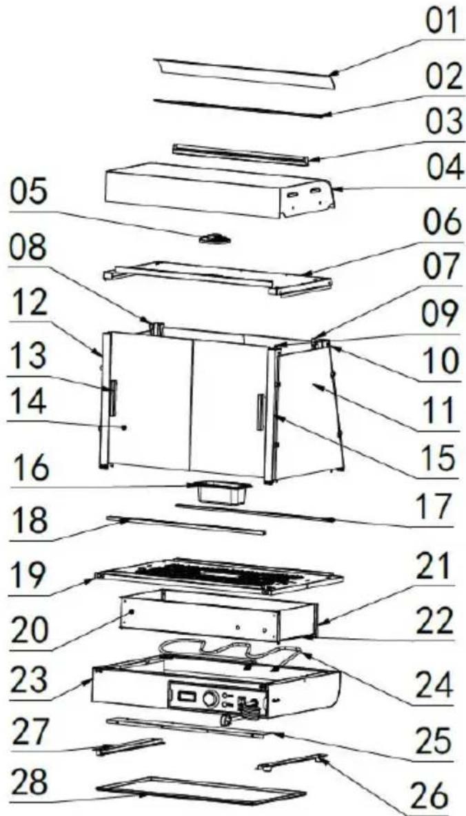
8.Product structure diagram
Note: The location of the electrical components is based on the design that time. Our company reserves the right to change the participating designs. If the design is changed and the instructions are not updated timely manner, we hope for your understanding!
| Exploded chart list | |||||
| No. | Name | Qty | No. | Name | Qty |
| 01 | Translucent cover | 1 | 15 | Mirror image of fro pillar | 1 |
| 02 | Translucent card slo | 2 | 16 | 0.5L basin | 1 |
| 03 | LED tube 600mm long | 1 | 17 | Glass chute inclined opening | 1 |
| 04 | Top cover | 1 | 18 | Glass chute straight mouth | 1 |
| 05 | Ultra-thin downlight 6W | 1 | 19 | Base table | 1 |
| 06 | Top cover bottom plate | 1 | 20 | Electrical box partition | 1 |
| 07 | Shelf column | 2 | 21 | Rear heat shield | 1 |
| 08 | Rear pillar | 1 | 22 | Side insulation pane | 2 |
| 09 | Aviation plug cable | 1 | 23 | Base | 1 |
| 10 | Rear pillar mirror | 1 | 24 | Heating pipe | 1 |
| 11 | Side glass | 2 | 25 | Electrical box sealing plate | 1 |
| 12 | Front pillar | 1 | 26 | No.1 machine foot | 4 |
| 13 | Aluminum T-shaped door handle | 4 | 27 | Slag basin guide ba | 2 |
| 14 | Front glass sliding door | 4 | 28 | Slag tray | 1 |
9.Product installation diagram:
| Parts kit bill of materials | ||||
| Applicable to models:SC-CJ-601、SC-CJ-602、SC-CJ-603、SC-CJ-60S | ||||
| A | B | C | D | E |
| Black spring washer | Black flat washer | Stainless steel hexagon socket bolts | Black round head screws | Black round head screws |
| M5 (8pcs) | M5 (8pcs) | M5X14 (4pcs) | M5X14 (8pcs) | M4X8 (8pcs) |
| F | G | H | I | J |
| Stainless steel padded screws (60s none) | Silicone gasket (60s none) | Glass card holder | Black T-shaped aluminum handle (60s none) | Screw tools |
| M4X12 (8PCS) | (16pcs) | (8pcs) | (4pcs) | (1pcs) |
| 60S Exclusive accessory | ||||
| K | L | M | N | |
| Black Ball Handle | Magnet door panel | Stainless Steel cross screw | Glass hinge set | |
| (1pcs) | (1pcs) | M5X18 (1pcs) | One for each top and bottom | |
| Note: The above are all the accessories in the accessory pack. During installation, you can find the screws whose codes in the above match the codes printed in the screw package according screws required in the installation steps for easy installation! | ||||
| Assembly parts list | |||
| ① | Left front pillar | ② | Right front pillar |
| 1PCS | 1PCS | ||
| ③ | Left rear pillar | ④ | Right rear pillar |
| 1PCS | 1PCS | ||
| ⑤ | Upper shelf - shortest | ⑥ | Middle shelf-medium |
| 1PCS | 1PCS | ||
| ⑦ | Lower shelf-longest | ⑧ | Shelf column |
| 1PCS | 2PCS | ||
| ⑨ | Shelf bracket-left | ⑩ | Shelf bracket-right |
| 3PCS | 3PCS | ||
| ⑪ | Front and rear glass slide doors(60s none) | ⑫ | Side glass |
| 4PCS | 2PCS | ||
| 60S Exclusive accessory (one each) | |||
| ⑬Rear glass door | ⑭Front glass flip door | ||
Note: The above are all accessories included in the accessory Please check whether the accessories are complete before inst
SC-CJ-60 Series Universal Installation Diagram
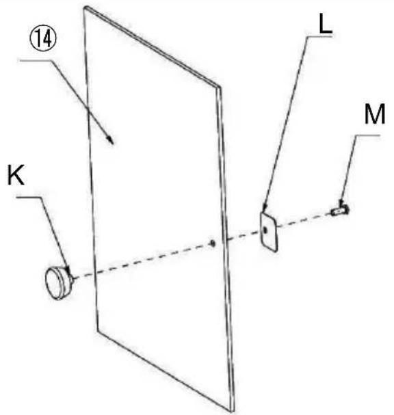
K (1PCS)
L (1PCS)
M (1PCS)
Step 1 (60s)
SC-CJ-60 Series Universal Installation Diagram
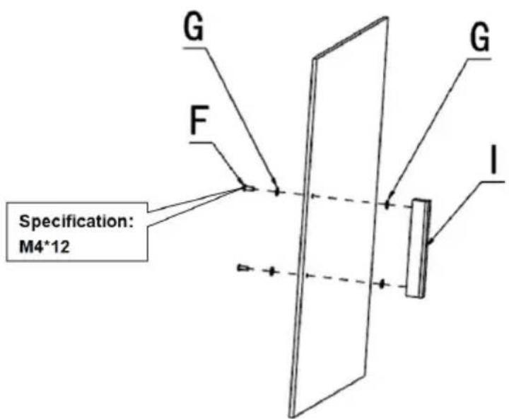
Step 1(601 602 603)
G (4PCS)
F (2PCS)
I (1PCS)
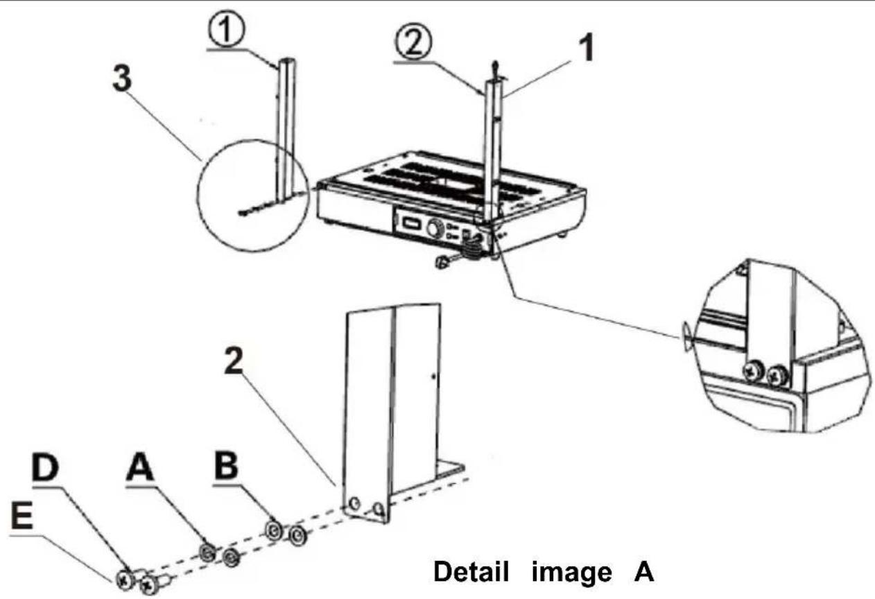
- Pass the light cord connector protruding from the base through column and hang it above the column.
Note: When installing the columns on both sides, please note to side with holes in the column faces the outside of the machine installation!
- According to the order of the picture, use the corresponding "D, A, B" to lock the accessories: "①, ②" on the reserved nut holes respectively.
3.Details image A
(1) (1PCS)
(1PCS)
A (4PCS)
B (4PCS)
D (4PCS)
E (Specification:M5*14)
Step 2
Detail image A
Detail image A
Specification: M5*14
D
A
B
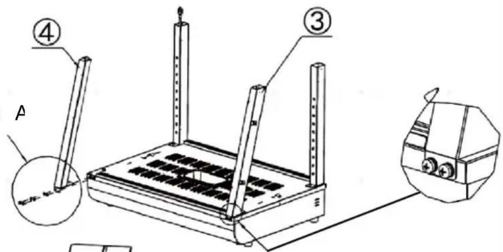
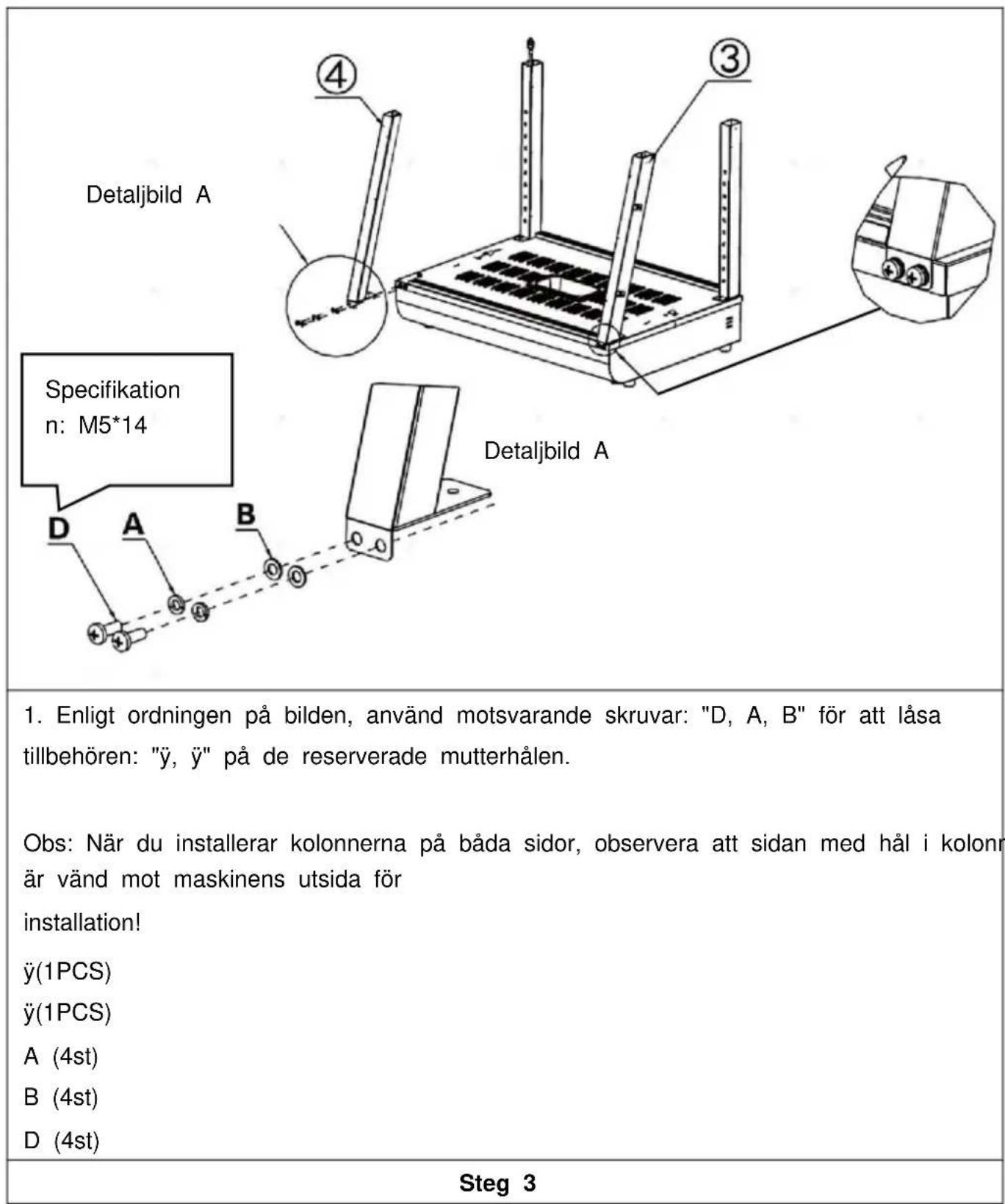
- According to the order of the picture, use the corresponding "D, A, B" to lock the accessories: "③, ④" on the reserved nut holes respectively.
Note: When installing the columns on both sides, please note the side with holes in the column faces the outside of the machine installation!
(3)(1PCS)
(4)(1PCS)
A (4PCS)
B (4PCS)
D (4PCS)
Step 3
Specification: M5*14
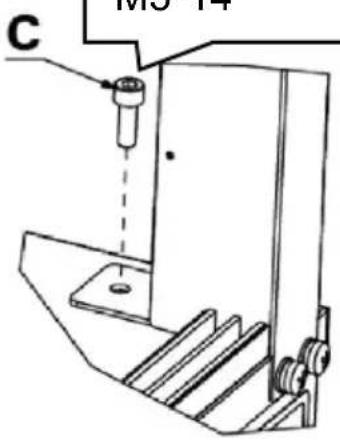
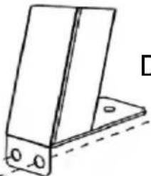
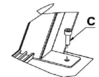
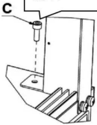
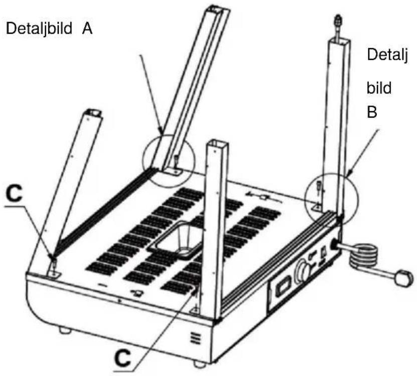
Detail image E
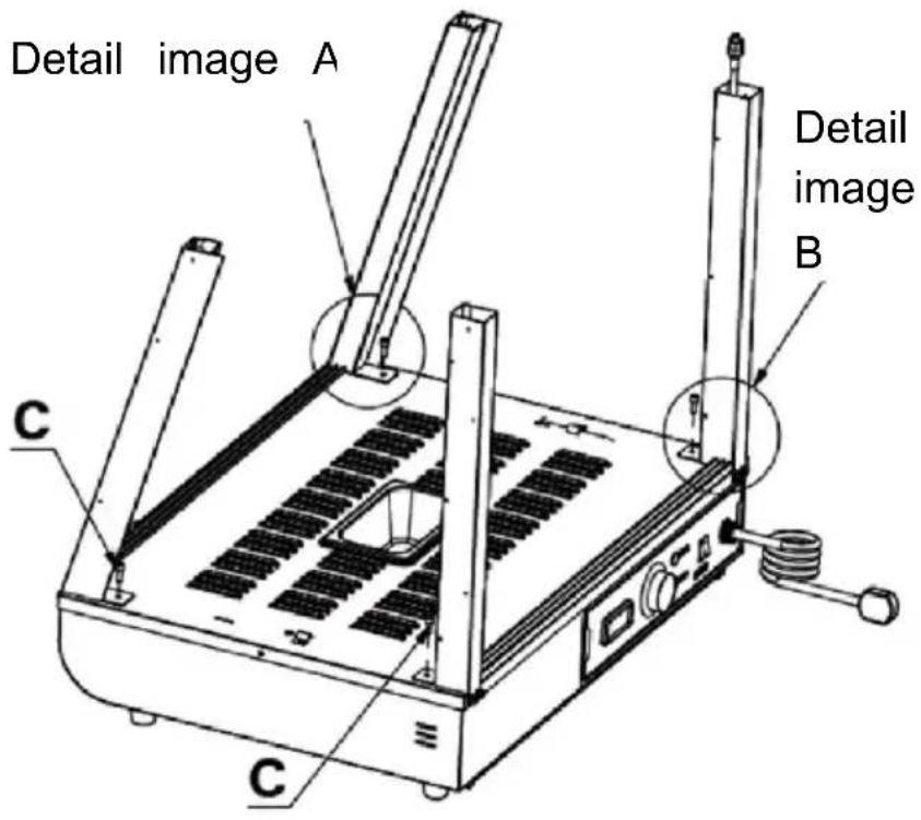
1.Use screw "C" to fix the four columns to the reserved nuts in the same way as shown in the detailed picture. C (4PCS)
Step 4
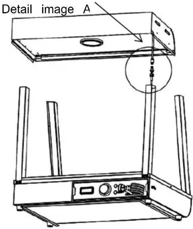
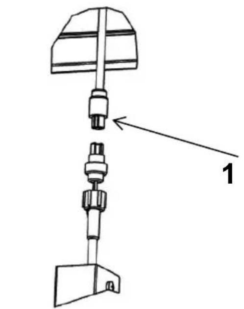
Detail image A
- Connect the wire connector protruding from the top cover to connector hanging on the column and tighten it, then insert the connected connector into the column and hide it.
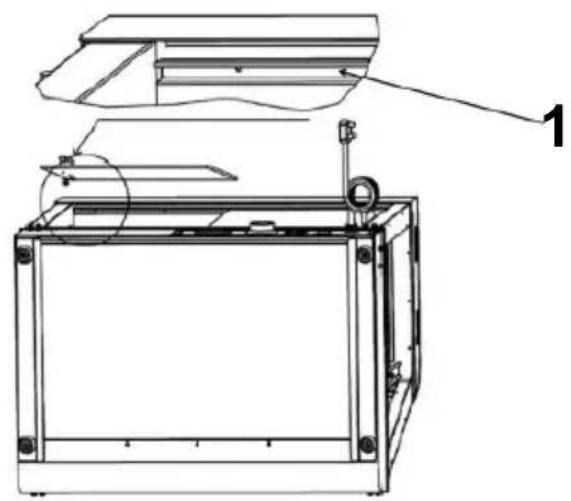
Step 5
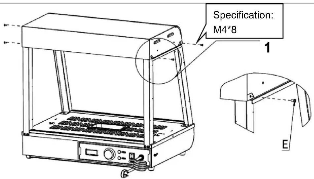
- Place the top cover on the four upright posts, and then use to fix the top cover and the upright posts (four in total).
E (4PCS)
Step 6
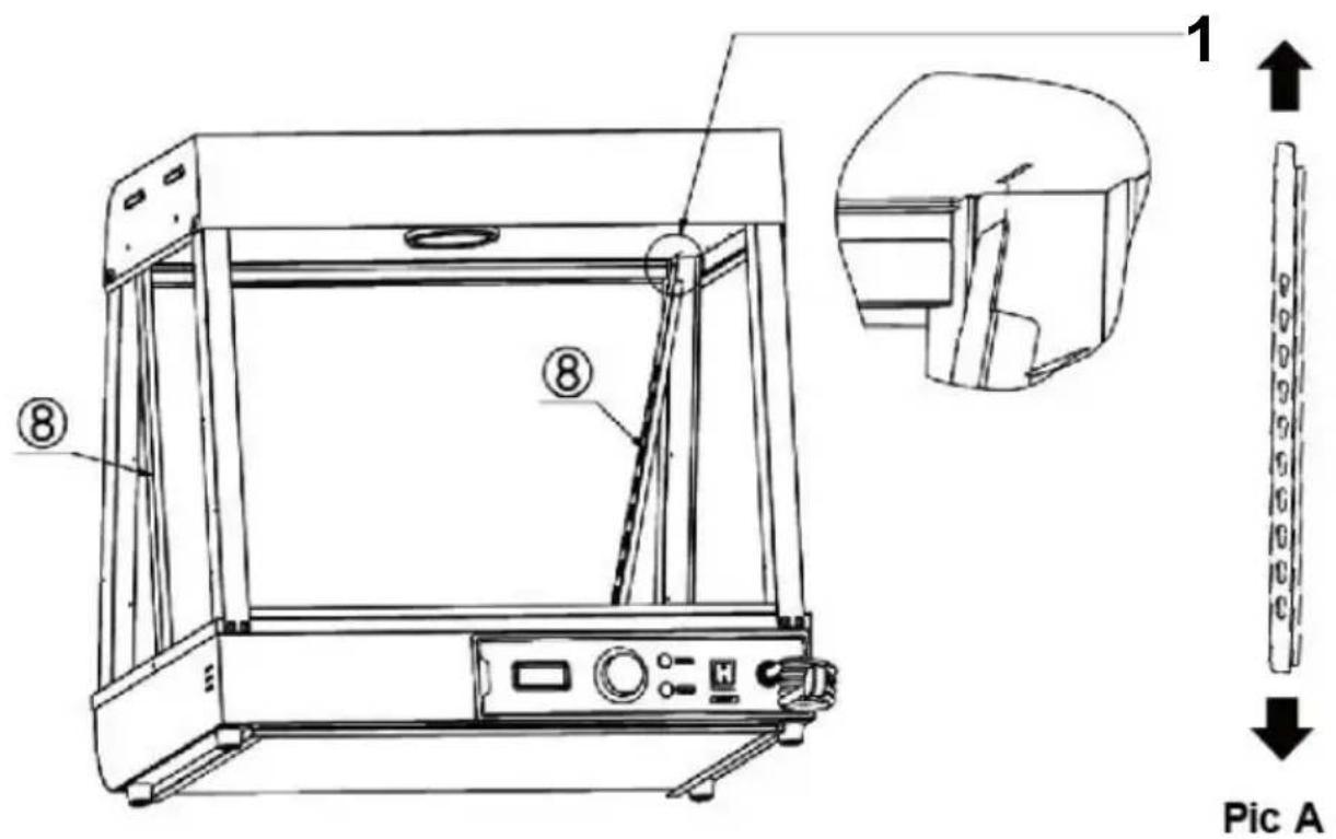
- Align the two left and right shelf pillars "⑧" in the same w direction of Figure A, then insert them diagonally into the resin on the top until they are fully inserted, and then align them.
Note: The position of accessory No. 8 is as shown in the figu- hole of the gourd hole is facing up, the small hole is facing o groove is facing the outside of the machine!
(2PCS)
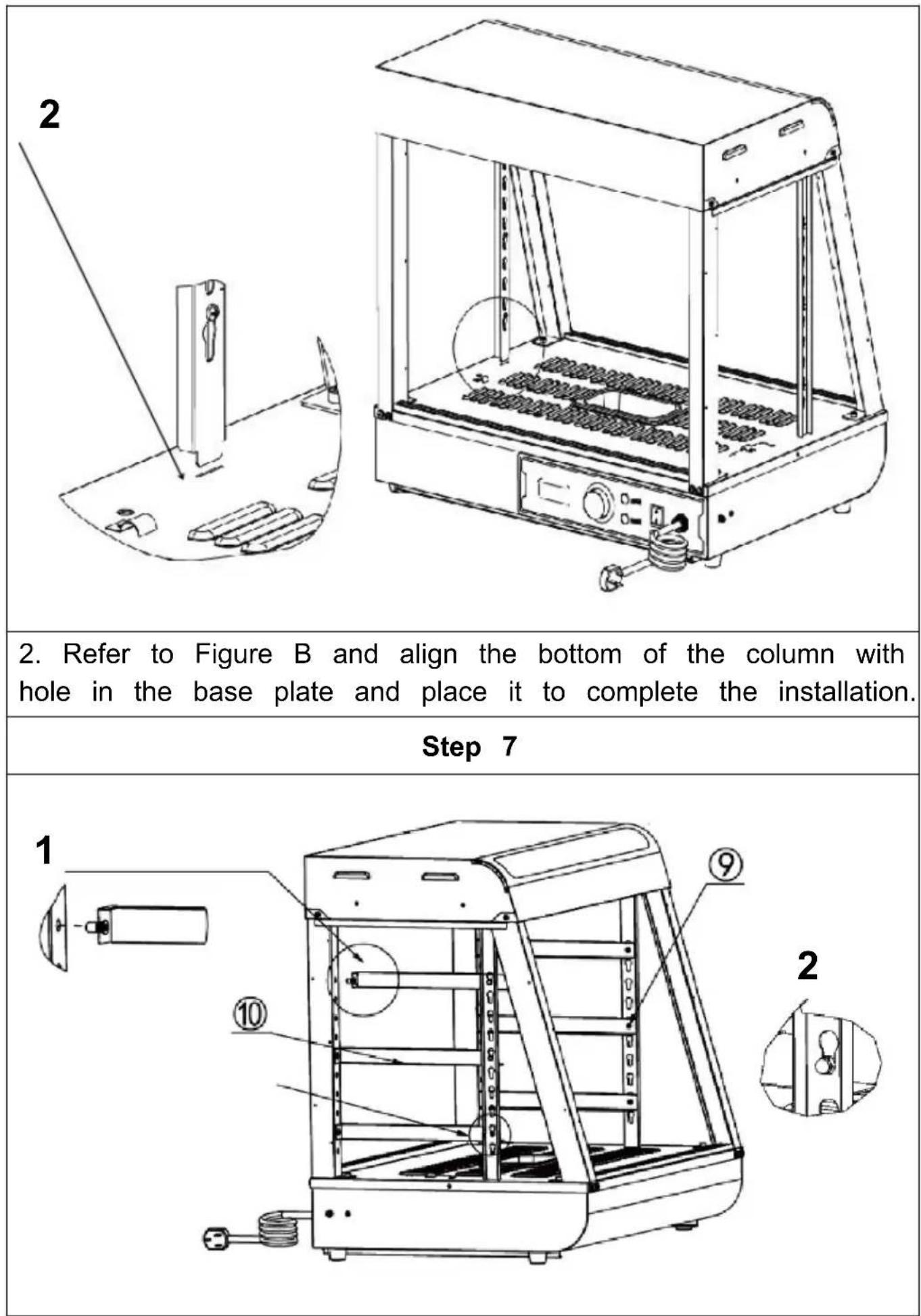
- First insert the ram nail on the front part of the part into t hole of the column as shown below. Note: Place the protruding part of the I-shaped nail on the shetoward the outside of the machine for installation!
- Then, insert the buckle nail at the rear of the part into the as shown in the picture below.
(3PCS)
(3PCS)
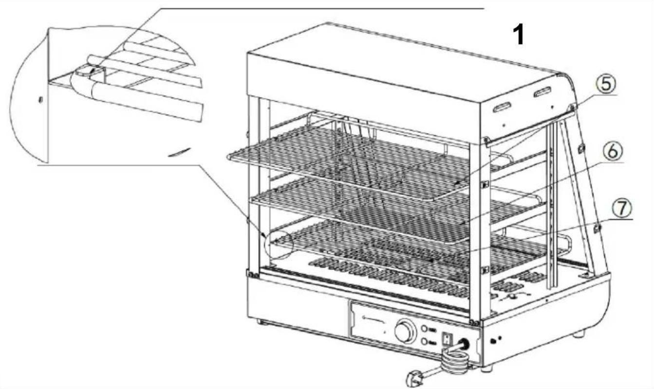
Step 8
- Place the parts, ⑥, ⑦" on the shelf bracket according to the positions shown in the picture, and push them into the reserved shown in the picture.
(5) (1PCS)
(1PCS)
(1PCS)
Step 9 (601 602 603)
- First, insert the front and rear glass sliding doors diagonally card slot set at the top, as shown in "Figure A"; after inserting extreme position, align the falling glass with the card slot below horizontal and vertical to the top card slot, as shown in "Figure installation is completed as shown in "Figure B". A total of four sliding doors at the front and rear are installed in the same way (4PCS)
Pic A
Notice:
- You need to install the inner piece of glass first and then a piece of glass;
- When installing, the upper card slot should be aligned horizontally with the lower card slot!
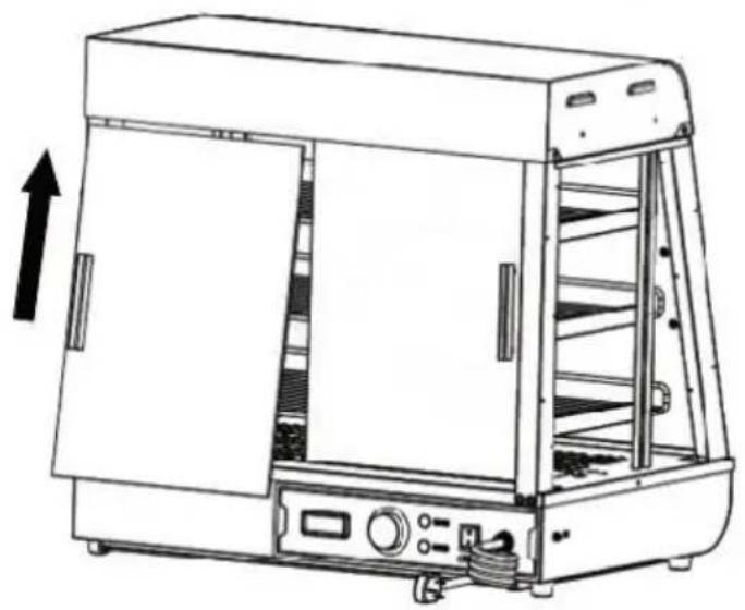
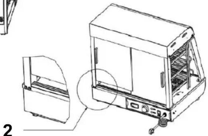
Step 9 (60S)
- First install the upper glass door hinge on the top of the g and tighten the screws.Then prepare the lower door hinge in the corresponding position.Finally, push the glass flip door into the p position of the lower hinge, and then tighten the screws of the hinge!
N(One for each top and bottom)
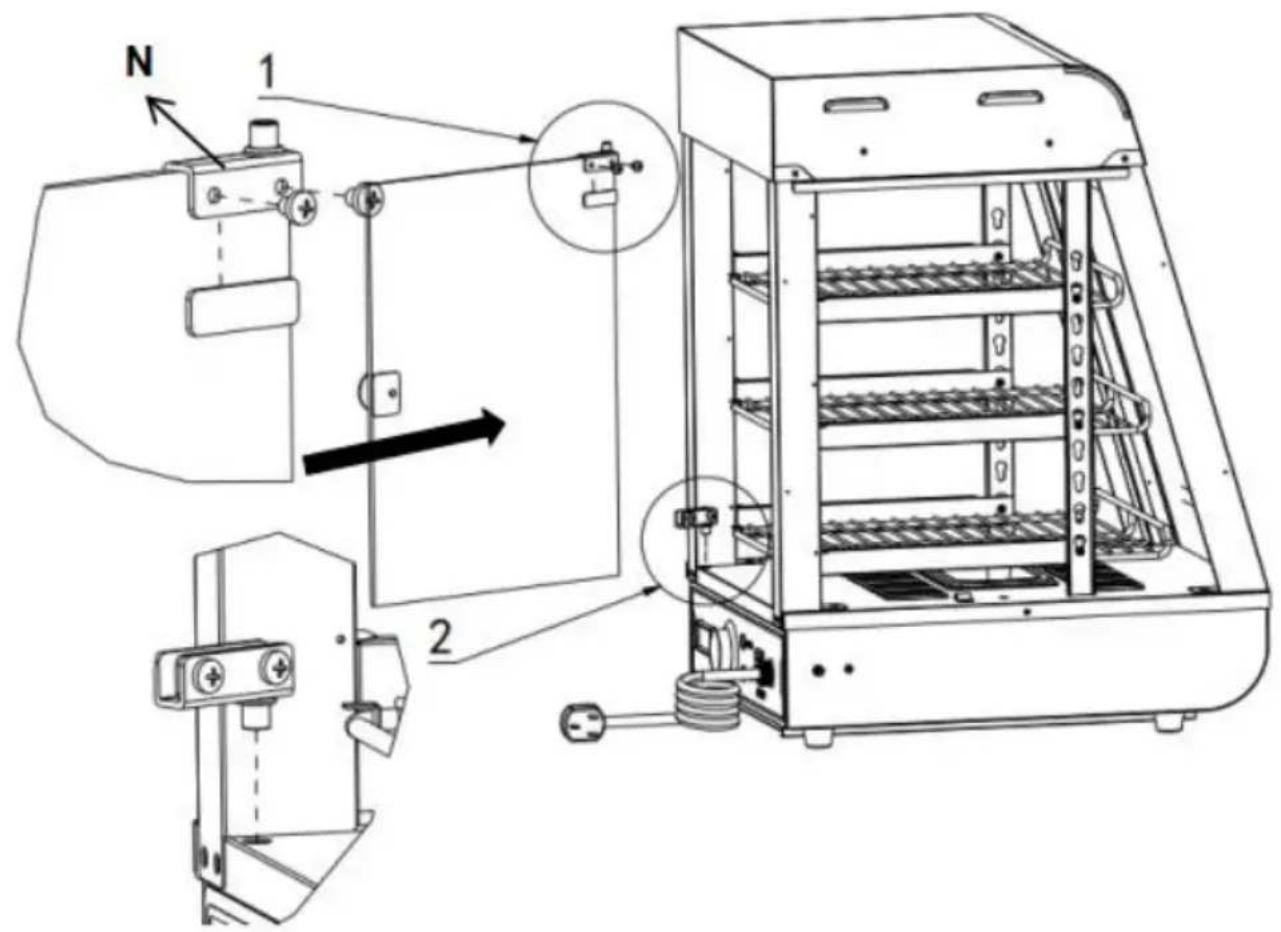
Install the door handle before the glass door(1PCS)
| Step 10 |
| Specification:M4*8 1 2 2. First install the upper glass door hinge on the top of the g and tighten the screws.Then prepare the lower door hinge in the corresponding position.Finally, push the glass flip door into the p position of the lower hinge, and then tighten the screws of the hinge! N(One for each top and bottom) Install the door handle before the glass door(1PCS) |
| Installation completed |
The position of the electrical parts is designed at that time, the company reserves the right to change the design of the evaluatic when the design changes and does not improve the manual in ti hope customers understand!
10. Circuit diagram
| SC-CJ-60S/SC-CJ-601 Electrical schematic diagram | ||
| L N PE | K1 HL3 ST HL2 FC | Illustrate |
| K1: Light switch HL1: Power indicator light HL2: Heating indicator light HL3 warm light ceiling lamp HL4:LED light tube FC: heating tube ST: Thermostat | ||
| SC-CJ-602/SC-CJ-603 Electrical schematic diagram | |
| L N PE | K1 HL1 ST HL2 FC HL3 Heating indicator light Heating indicator light Heating light cooling lamp 1 Heating light cooling lamp 2 LED light tube Heating tube Thermostat |
- Fault analysis and troubleshooting:
| NO. | Fault phenomenon | Reason | Method of exclusion |
| 01 | The indicator light does not light up when the device is turned on. | Power switch fuse blown | ①Replace with a suitable fuse ②Plug in the power cord firmly |
| 02 | The green and red indicator lights are at the same time at the temperature does not rise. | The electric heating tube wiring is loose at the electric heating tube is burned out. | ①Tighten the electric heating pipe wiring bolts. ②Replace the electric heating tube |
| 03 | The work indicator light stays on and the temperature rise cannot be controlled. | Thermostat failure | ①Replace the thermostat |
| 04 | The indicator light is off and the temperature control is normal | Indicator light burned out | ①Replace the indicator light |
| 05 | It cannot automatically keep warm. | Thermostat failure | ①Replace the thermostat |
| 06 | There is a tingling sensation in the hands due to leakage from the casing. | The insulation is damp or the inner conductor is in contact with the outer shell. | ①Send it to the maintenance department for repair |
| 07 | The light does not come on or flickers. | The cable interface is not connected or has poor contact. | ①Plug it in tightly |
Note: The above problems are only for analysis and reference not deal with them by yourself. Relevant professionals are require conduct troubleshooting and repairs. In case of safety abnormality as leakage, the power supply should be cut off immediately and should be stopped!
Please keep this manual properly
Manufacturer: Shanghaiuxinmuyeyouxianggsi
Address: Shuangchenglu 803nong11hao1602A-1609shi, baoshanqu, shanghai 200000 CN.
Imported to AUS: SIHAO PTY LTD. 1 ROKEVA STREETEASTWOOD NSW 2122 Australia
Imported to USA: Sanven Technology Ltd. Suite 250, 9166 Anaheim Place, Rancho Cucamonga, CA 91730
| UK | REP |
YH CONSULTING LIMITED. C/O YH Consultin Limited Office 147, Centurion House, London Road, Staines-upon-Thames, Surrey, TW18 4A
| EC | REP |
Technical Support and E-Warranty Certificate
www.vevor.com/support
VEVOR
TOUGH TOOLS, HALF PRICE
Assistance technique et certificat de garantie electronique www.vevor.com/support
Affichage du chauffe-plats
YH CONSULTING LIMITEE. C/O YH Consulting Limited Bureau 147, Centurion House, London Road, Staines-upon-Thames, Surrey, TW18 4AX
| REPRÉSENT | ANT CE |
E-CrossStu GmbH
Mainzer Landstr.69,
YH CONSULTING LIMITED. C/O YH Consulting Limited Office 147, Centurion House, London Road, Staines-upon-Thames, Surrey, TW18 4AX
www.vevor.com/support
VEVOR®
TOUGH TOOLS, HALF PRICE
Importato in Australia: SIHAO PTY LTD. 1 ROKEVA STREETEASTWOOD NSW 2122 Australia
YH CONSULENZA LIMITATA. C/O YH Consulting Limited Office 147, Centurion House, London Road, Stainesupon-Thames, Surrey, TW18 4AX
| REP.CE |
E-CrossStu GmbH
Mainzer Landstr.69, 60329 FrancofortesulMeno.
VEVOR
TOUGH TOOLS, HALF PRICE
elettronica www.vevor.com/support
VEVOR
TOUGH TOOLS, HALF PRICE
Soporte专业技术 y certificate de garantia electrònica www.vevor.com/support
YH CONSULTING LIMITADO. C/O YH Consulting Limited Oficina 147, Centurion House, London Road, Staines-upon-Thames, Surrey, TW18 4AX
E-CrossStu GmbH
Mainzer Landstr.69, 60329 Francfort del Meno.
VEVOR
TOUGH TOOLS, HALF PRICE
ODPOWIEDZIALNOŚCIA. C/O YH Consulting Limited
Office 147, Centurion House, London Road, Staines-upon-Thames, Surrey, TW1
| REPREZE NT KE |
E-CrossStu GmbH
Mainzer Landstr.69,
60329 Frankfurt nad Menem.
VEVOR
TOUGH TOOLS, HALF PRICE
www.vevor.com/support
VEVOR
TOUGH TOOLS, HALF PRICE
Technische ondersteuning en e-garantiecertificaat www.vevor.com/support
Voedselverwarmer-display
Model: SC-CJ-60S/SC-CJ-601/
SC-CJ-602/SC-CJ-603
HULP NODIG? NEEM CONTACT MET ONS OP!
Hoefft u productvragen? Technische ondersteuning nodig? Neem gerust contact met ons op: Technische
ondersteuning en e-garantiecertificaat www.vevor.com/support
YH CONSULTING LIMITED. C/O YH Consulting Limited Office 147, Centurion House, London Road, Staines-upon-Thames, Surrey, TW18 4AX
garantiecertificaat www.vevor.com/support
VEVOR
TOUGH TOOLS, HALF PRICE
A (4st)
B (4st)
D (4st)
E (Specification: M5*14)
Steg 2

Specification:
M5*14
Detaljbild B
Detailbild A
YH CONSULTING LIMITED. C/O YH Consulting Limited Office 147, Centurion House, London Road, Staines-upon-Thames, Surrey, TW18 4AX

www.vevor.com/support