YUKIAIR PAC1000P - Air Conditioning AIWA - Free user manual and instructions
Find the device manual for free YUKIAIR PAC1000P AIWA in PDF.
| Product Type | Portable Monoblock Air Conditioner |
| Brand | Aiwa |
| Model | YUKIAIR PAC1000P |
| Refrigerant | R290 (propane) - flammable |
| Operating Modes | Cooling, heating (depending on version), dehumidification, fan, sleep |
| Fan Speeds | 2 speeds: high and low |
| Display | LED Digital Display |
| Timer | Programmable (1h to 24h) for automatic on/off |
| Remote Control | Yes, included |
| WiFi Connectivity | Yes, compatible with Smart Life app (iOS/Android) |
| Auto-evaporation | Yes, automatically removes humidity in cooling mode |
| Auto-defrost | Yes, at low ambient temperature |
| Auto shut-off when tank full | Yes, with water level indicator |
| Child Lock | Yes, via control panel |
| Auto-restart | Yes, after power outage (3-minute delay to protect compressor) |
| Air Filter | Washable, cleaning recommended every 2 weeks |
| Manual Drainage | Drain plug at back |
| Continuous Drainage | Possible with included hose (slope >20° downward) |
| Included Accessories | Exhaust hose, window kit, adapter, remote control, drainage hose, manual |
| Installation Conditions | Room >9 m², free space >50 cm around, flat and stable surface |
| Safety | Uses flammable refrigerant (R290) – strict precautions, no ignition source, fire extinguisher nearby |
Frequently Asked Questions - YUKIAIR PAC1000P AIWA
User questions about YUKIAIR PAC1000P AIWA
0 question about this device. Answer the ones you know or ask your own.
Ask a new question about this device
Download the instructions for your Air Conditioning in PDF format for free! Find your manual YUKIAIR PAC1000P - AIWA and take your electronic device back in hand. On this page are published all the documents necessary for the use of your device. YUKIAIR PAC1000P by AIWA.
USER MANUAL YUKIAIR PAC1000P AIWA
natural_image
White industrial air purifier unit with closed lid and wheels (no visible text or symbols)YUKIAIR PAC-10000P | SETSUAIR PAC-10000PH
(EN) Portable Air Conditioner - Instruction Manual
(ES) Aire Acondicionado portátil - Manual de instrucciones
(IT) Condizionatore portatile - Manuale di istruzioni
(FR) Climatiseur portatif - Manuel d'instructions
(DE) Tragbare Klimaanlage – Bedienungsanleitung
(BG) Преносим климатик - Инструкция за експлоатация
(EL) Φορητό Κλιματιστικό - Εγχειρίδιο οδηγιών
(PT) Ar Condicionado Portátil – Manual de Instruções
(RO) Aer conditionat portabil - Manual de instructiuni
(HU) Hordozható légkondicionáló – használati útmutató
(RU) Портативный кондиционер – Руководство по эксплуатации
(HE) כרִיְבָרִיְבָר - כרִיְבָר
ENGLISH
natural_image
Warning sign depicting a flame inside a triangle (no text or symbols)


aiwa
1. BEFORE YOU BEGIN
1.1 PRODUCT DESCRIPTION
Our powerful portable air conditioners are great cooling solutions for single rooms, creating a comfortable atmosphere in your space. It also has ventilation and dehumidifying function for circulating air and removal of moisture. They're self-contained systems that do not require any permanent installation allowing you to move to the space in which it is most needed. They're commonly used in kitchen, temporary-resided, computer rooms, garages, and many other places where installation of Air-conditioner Outdoor Unit is limited.
The environmentally friendly R290 is used as the refrigerant. R290 has no damaging influence on the ozone layer (ODP), a negligible greenhouse effect (GWP) and is available worldwide. Because of its efficient energy properties, R290 is highly suitable as a coolant for this application. Special precautions must be taken into consideration due to the coolant's high flammability.
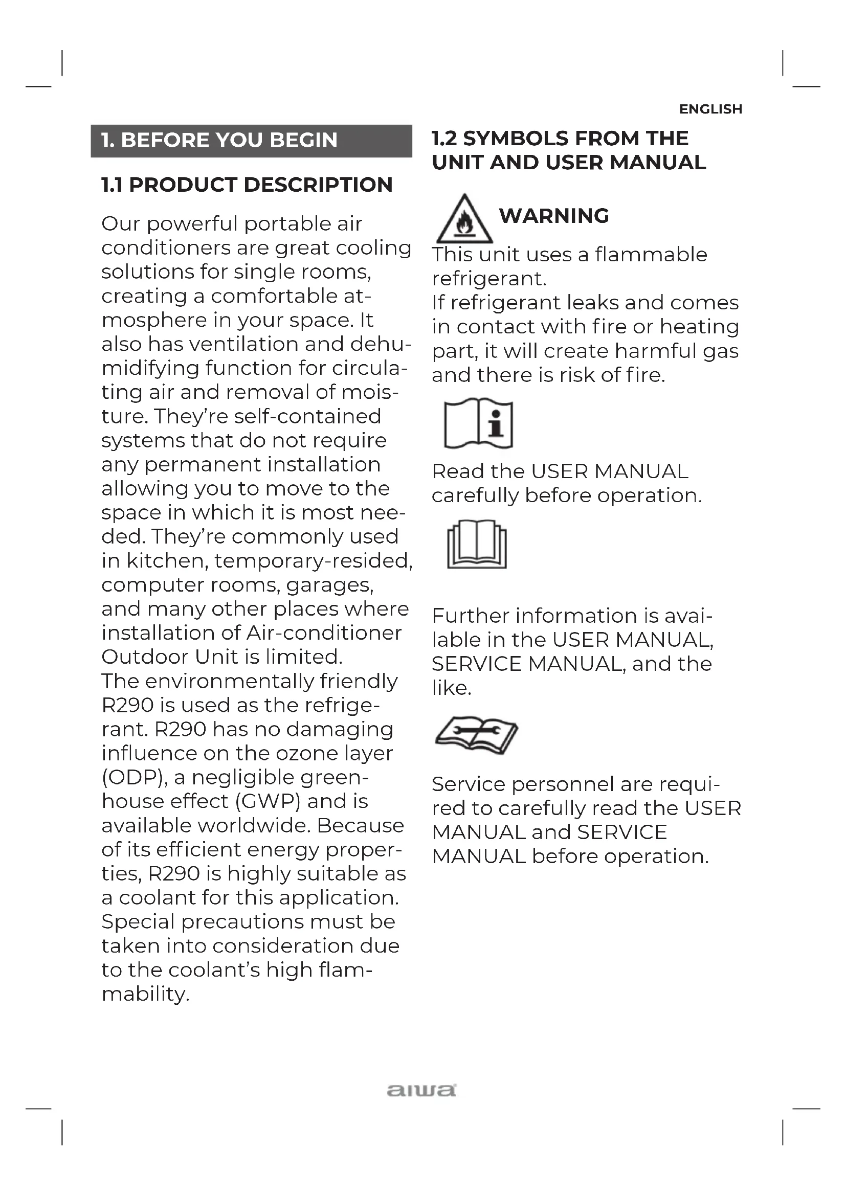
1.2 SYMBOLS FROM THE UNIT AND USER MANUAL
WARNING
This unit uses a flammable refrigerant.
If refrigerant leaks and comes in contact with fire or heating part, it will create harmful gas and there is risk of fire.

Read the USER MANUAL carefully before operation.

Further information is available in the USER MANUAL, SERVICE MANUAL, and the like.

Service personnel are required to carefully read the USER MANUAL and SERVICE MANUAL before operation.
ENGLISH
THE FOLLOWING SHOULD ALWAYS BE OBSERVED FOR SAFETY
■This appliance is intended to be used by expert or trained users in shops, in light industry and on farms, or for commercial use by lay persons.
■This appliance can be used by children aged from 8 years and above and persons with reduced physical, sensory or mental capabilities or lack of experience and knowledge if they have been given supervision or instruction concerning use of the appliance in a safe way and understand the hazards involved. Children shall not play with the appliance. Cleaning and user maintenance shall not be made by children without supervision.
■The unit is designed only for use with R-290(propane) gas as the designated refrigerant.
■The refrigerant loop is sealed. Only a qualified technician should attempt to service!
■Do not discharge the refrigerant into the atmosphere.
■R-290 (propane) is flammable and heavier than air.
■It collects first in low areas but can be circulated by the fans.
■If propane gas is present or even suspected, do not allow untrained personnel to attempt to find the cause.
■The propane gas used in the unit has no odor.
■The lack of smell does not indicate a lack of escaped gas.
■If a leak is detected, immediately evacuate all persons from the store, ventilate the room and contact the local fire department to advise them that a propane leak has occurred.
■Do not let any persons back into the room until the qualified service technician has arrived and that technician advises that it is safe to return to the room.
■No open flames, cigarettes or other possible sources of ignition should be used inside or in the vicinity of the units.
■Component parts are designed for propane and non-incentive and non-sparking. Component parts shall only be replaced with identical repair parts.
ENGLISH
FAILURE TO ABIDE BY THIS WARNING COULD RESULT IN AN EXPLOSION, DEATH, INJURY AND PROPERTY DAMAGE.
2. FOR YOUR SAFETY
Your safety is the most important thing we concerned!
WARNING
Please read this manual carefully and fully understand before operating your appliance.
2.1 OPERATIONAL PRECAUTIONS
WARNING- to reduce the risk of fire, electric shock or injury to persons or property:
■Please let the portable air conditioner stand upright for at least 24 hours before plugging in.
■If the supply cord is damaged, it must be replaced by the manufacturer, its service agent or similarly qualified persons in order to avoid a hazard.
■The appliance shall be disconnected from its power source during service.
■Always operate the unit from a power source of
equal voltage, frequency and rating as indicated on the product identification plate.
■Always use a power outlet that is grounded.
■Unplug the power cord when cleaning or when not in use.
■Do not operate with wet hands. Prevent water from spilling onto the unit.
■Do not immerse or expose the unit to rain, moisture or any other liquid.
■Do not leave the unit running unattended. Do not tilt or turn over the unit.
■Do not unplug while the unit is operating.
■Do not unplug by pulling on the power cord.
■Do not use an extension cord or an adapter plug.
■Do not put objects on the unit.
■Do not climb or sit on the unit.
■Do not insert fingers or other objects into the air outlet.
■Do not touch the air inlet or the aluminum fins of the unit.
■ Do not operate the unit if it is dropped, damaged or showing signs of product malfunction.
■ Do not clean the appliance
ENGLISH
with any chemicals.
■ Ensure the unit is far away from fire, inflammable, or explosive objects.
■ The unit shall be installed in accordance with national wiring regulations.
■ Do not use means to accelerate the defrosting process or to clean, other than those recommended by the manufacture.
■ The appliance shall be stored in a room without continuously operation sources (for example: open flames, an operating gas appliance or an operating electric heater).
■ The appliance shall be stored so as to prevent mechanical damage from occurring.
■ Do not piece or burn, even after use.
■ Be aware that refrigerants may not contain an odour.
■ Pipe-work shall be protected from physical damage and shall not be installed in an unventilated space, if that space is smaller than 9 m ^2 .
■ Compliance with national gas regulations shall be observed.
- Keep any required ventilation openings clear of obstruction.
■The appliance shall be sto-
red in a well-ventilated area where the room size corresponds to the room area as specified for operation.

WARNING
Any person who is involved with working on or breaking into a refrigerant circuit should hold a current valid certificate from an industry-accredited assessment authority, which authorizes their competence to handle refrigerants safely in accordance with an industry, recognized assessment specification.

WARNING
Servicing shall only be performed as recommended by the equipment manufacturer. Maintenance and repair requiring the assistance of other skilled personnel shall be carried out under the supervision of the person competent in the use of flammable refrigerants.
If you don't understand something or need help, please contact the dealer services.
2.2 SAFETY PRECAUTIONS ON SERVICING
Please follow these warnings when to undertake the following when servicing an appliance with R290.
2.2.1 Checks to the area
Prior to beginning work on systems containing flammable refrigerants, safety checks are necessary to ensure that the risk of ignition is minimized. For repair to the refrigerating system, the following precautions shall be complied with prior to conducting work on the system.
2.2.2 Work procedure
Work shall be undertaken under a controlled procedure so as to minimize the risk of a flammable gas or vapor being present while the work is being performed.
2.2.3 General work area
All maintenance staff and others working in the local area shall be instructed on the nature of work being carried out. Work in confined spaces shall be avoided. The area around the work space shall be sectioned off. Ensure that the conditions within the area have been made safe by control of flammable material.
2.2.4 Checking for presence of refrigerant
The area shall be checked with an appropriate refrigerant detector prior to and during work, to ensure the technician is aware of potentially flammable atmospheres. Ensure that the leak detection equipment being used is suitable for use with flammable refrigerants, i.e. no sparking, adequately sealed or intrinsically safe.
2.2.5 Presence of fire extinguisher
If any hot work is to be conducted on the refrigeration equipment or any associated parts, appropriate fire extinguishing equipment shall be available to hand. Have a dry powder or CO2 fire extinguisher adjacent to the charging area.
2.2.6 No ignition sources
No person carrying out work in relation to a refrigeration system which involves exposing any pipe work that contains or has contained flammable refrigerant shall use any sources of ignition in such a manner that it may lead to the risk of fire or explosion. All possible ignition sources, including cigarette smoking, should be kept
ENGLISH
sufficiently far away from the site of installation, repairing, removing and disposal, during which flammable refrigerant can possibly be released to the surrounding space.
Prior to work taking place, the area around the equipment is to be surveyed to make sure that there are no flammable hazards or ignition risks. "No Smoking" signs shall be displayed.
2.2.7 Ventilated area
Ensure that the area is in the open or that it is adequately ventilated before breaking into the system or conducting any hot work. A degree of ventilation shall continue during the period that the work is carried out. The ventilation should safely disperse any released refrigerant and preferably expel it externally into the atmosphere.
2.2.8 Checks to the refrigeration equipment
Where electrical components are being changed, they shall be fit for the purpose and to the correct specification. At all times the manufacturer's maintenance and service guidelines shall be followed. If in doubt consult the manufacturer's technical department for assistance. The following checks shall be applied to installations using flammable refrigerants:
- The charge size is in accordance with the room size within which the refrigerant containing parts are installed;
• The ventilation machinery and outlets are operating adequately and are not obstructed;
- If an indirect refrigerating circuit is being used, the secondary circuit shall be checked for the presence of refrigerant;
- Marking to the equipment continues to be visible and legible. Markings and signs that are illegible shall be corrected;
- Refrigeration pipe or components are installed in a position where they are unlikely to be exposed to any substance which may corrode refrigerant containing components, unless the components are constructed of materials which are inherently resistant to being corroded or are suitably protected against being so corroded.
2.2.9 Checks to electrical devices
Repair and maintenance to electrical components shall
include initial safety checks and component inspection procedures. If a fault exists that could compromise safety, then no electrical supply shall be connected to the circuit until it is satisfactorily dealt with. If the fault cannot be corrected immediately but it is necessary to continue operation, an adequate temporary solution shall be used. This shall be reported to the owner of the equipment so all parties are advised. Initial safety checks shall include:
- Those capacitors are discharged: this shall be done in a safe manner to avoid possibility of sparking;
- That there no live electrical components and wiring are exposed while charging, recovering or purging the system;
- That there is continuity of earth bonding.

WARNING
Install the unit in rooms which exceed 9 m ^4 .
Do not install the unit in a place where inflammable gas may leak.

NOTE
The manufacturer may provide other suitable example or may provide additional information about the refrigerant odour.
3. PRODUCT OVERVIEW
3.1 PRODUCT DIAGRAM FIGURE N° 1 (AT THE END OF THE BOOK)
1 Control panel
2 Air outlet with adjustable louver
3 Handle
4 Air inlet with air filter
5 Caster
6 Drainage Hole
5 Caster
7 Air Exhaust
Note: The appearance is only for reference. Please see the real product for detailed information.
3.2 FEATURES
- High Capacity in a compact size with fan, cooling, heating and dehumidifying function.
• Temperature setting and display - LED Digital display
- Electronic control with built-in timer, sleep mode
- Self-evaporating system for better efficient
- Auto shut off when tank full
- Automatic restart in the event of power outage
- Auto defrosting function at low ambient temperatures
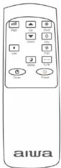
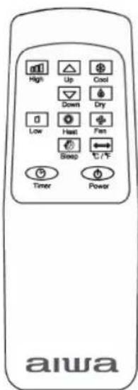
- Remote control
- 2- speed fan
- Casters for easy mobility
ENGLISH
4. INSTALLATION
4.1 UNPACKING
- Unpack the carton and take the appliance and accessories out.
- Check the device after unpacking for any damage or scratches on it.
-
Accessories:
-
Exhaust hose
-
Hose connector
-
Window kit adapter
-
Remote control
-
Water pipe
-
Window kit
-
User manual
FIGURE N° 2
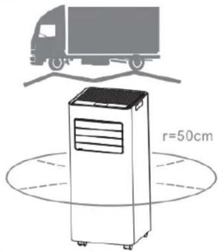
4.2 Choose your location
■ If tipped more than 45^ , allow the unit to set upright for at least 24 hours before start up.
■ Place the unit on a firm, level surface in an area with at least 50cm of free space around it to allow for proper air circulation.
■ Do not operate in close proximity to walls, curtains, or other objects that may block air inlet and outlet. Keep the air inlet and outlet free of obstacles.
■ Never install the unit where it could be subject to:
- Heat sources such as radiators, heat registers, stoves or other products that products that produce heat.
- Direct sunlight
- Mechanical vibration or shock
- Excessive dust
- Lack of ventilation, such as cabinet or bookcase
- Uneven surface
FIGURE N° 3
4.3 ATTACH THE EXHAUST HOSE
The air conditioner requires being vented outside so that the exhaust air can escape the room which coming from the appliance contains waste heat and moisture.
Do not replace or extend exhaust hose which will result in decreased efficiency, even worse shut down the unit due to low backpressure.
Step 1: Connect the hose connector to one end of the exhaust hose.
FIGURE N°4
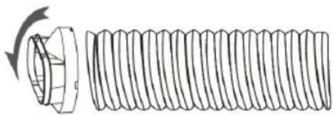
Step 2: Connect the windows kit adapter to the other end of the exhaust hose.
FIGURE N°5
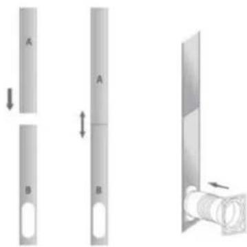
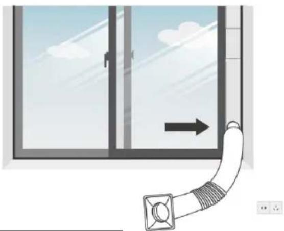
Step 3: Extend the adjustable window kit the length of your window. Connect the exhaust hose to the window kit.
FIGURE N°6
Step 4: Close your window to secure the kit in place. It needs to hold the windows kit firmly in place, secure the window kit with duct tape if required. It is recommended that the gap between the adapter and the sides of the window should be sealed off for maximum efficiency. FIGURE N°7
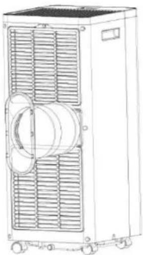
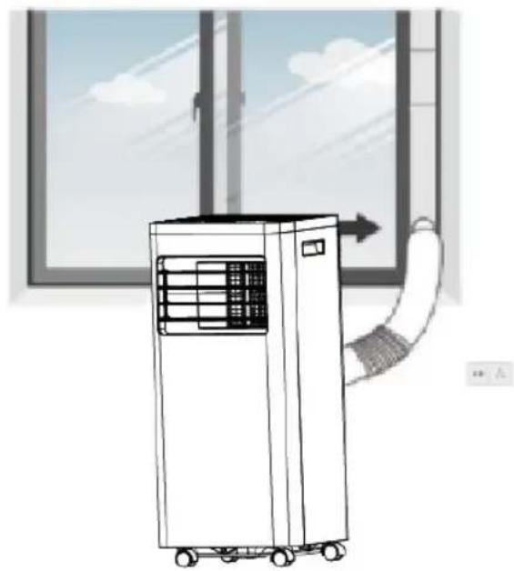
Step 5: Attach the hose connector to the exhaust air outlet of unit. FIGURE N°8
Step 6: Adjusting the length of the flexible exhaust hose, and avoid bends in the hose. Then place AC near an electrical outlet. FIGURE N°9
Step 7: Adjust the louver at the air outlet, and then switch on the unit.
5. OPERATION
5.1 CONTROL PANEL AND DISPLAY
FIGURE N°10 (Control Panel)
1. POWER
Press to switch the machine on or off.
2. MODE
Mode button Press to switch the operation mode between fan, cooling, heating and dehumidifier.
3. SPEED
Press to switch the fan speed between HIGH and LOW.
4. DOWN
Decreasing the desired temperature (32°C-16°C) or timer setting(0-24h).
5. UP
Increasing the desired temperature (16°C-32°C) or timer setting(0-24h).
6. TIMER
Sets a time for the unit to automatically start or stop.
7. SLEEP
Press to turn on sleep mode or off.
8. LOCK
Press to turn on or turn off the child lock function.
5.3.1 Start-up and Shutdown
■ Press POWER to turn the unit on.
- Press MODE button to select the desired operation mode.
■ Press POWER again to turn off the power.
5.3.2 Operation mode
The unit has four operation modes: Cool, heat, dry, fan and sleep.
A. Cooling your room
Select the cool mode to lower the temperature in your room.
- Press MODE button repeatedly until the Cool indicator lights up.
- Press Up/Down button to adjust the temperature which is displayed on the screen. The temperature can be set between 16°C and 32°C.
- Press SPEED button repeatedly until the desired fan speed indicator lights up.
To control the direction of the air flow horizontally, please adjust the inner louver by hand.
Note: The air conditioner stops if the room temperature is lower than selected temperature.
B. Heating your room(Optional for Heating Function Unit only)
- Press MODE button repeatedly until the HEAT indicator lights up.
- Press Up/Down button to set the temperature higher than the room temperature. The fan speed can also be set.
ENGLISH
Note: The drainage hose should be attached to the unit for continuous operating.
C. Ventilating your room
- Press MODE button repeatedly until the FAN indicator lights up. In ventilation mode the room air is circulated, but not cooled.
- Press SPEED button repeatedly to select the fan speed as desired.
D. Drying your room
- Press MODE button on the control panel or remote control, the dry indicator lights up. The fan speed is unable to select. User should connect the hose to the drain outlet at the bottom of the unit.
Note: In this mode, the fan speed switches over to low speed and cannot be selected.
E.Sleep mode
The sleep mode can be activated when in cool mode.
In cool mode: After 1 hour the preset temperature is increased by 1^ C, after another hour the preset temperature will again be increased by 1^ C.
In heat mode (Optional for Heating Function Unit only):
After 1 hour the preset temperature is decreased by 1^ C, after another hour the preset temperature will again be decreased by 1^ C.
Then the temperature is kept constant for 10 hours. And all the indicators dim to dark. The fan speed may switch over to low speed for silent operating and cannot be selected.
5.3.3 TIMER SETTING (1hour-24hours):
The timer has two ways of operation:
To turn off (When power on)

Press Timer key to turn on the timer function.

Press Up /Down repeatedly to set the delay OFF time.
To turn on (When power off)

Press Timer key to turn on the timer function.

Press Up /Down repeatedly to set the delay ON time.
Cancel timer

Press Up /Down repeatedly until the LED shows '00'.
Note: when press POWER will also exit the timer setting.
5.3.4 Automatic Defrost
At low room temperatures, frost may buildup at the evaporator during operation. The unit will automatically start defrosting and the POWER LED blinking. The defrost control sequence is as follows:
A. When the unit operates in the cooling operation, drying operation, the ambient temperature sensor senses the evaporator coil temperature is below -1°C, after the compressor will stop operating for 10 minutes or the coil temperature up to 7°C, the unit restart to cool operating mode.
B. When the unit operates in the heating operation, drying operation, once the coil temperature sensor senses the temperature of the evaporator is below 40^ C and the differential temperature between coil temperature and room temperature is below 19^ C after the compressor operation for 20 minutes, the unit start defrosting for 5 minutes and the power indicator blinking.
5.3.5 Overload Protection
In the event of a power loss, to protect the compressor there is a 3-minute delay until the compressor restarting.
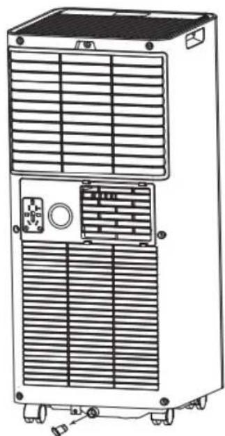
5.4 DRAINAGE
Manual drainage:
1) When the machine stops after the water is full, please unplug the power plug.
Notes: Please move the machine carefully, so as not to spill the water in the water pan at the bottom of the unit.
2) Place the water container below the side water outlet behind the unit.
3) Unplug the water plug, the water will automatically flow into the water container.
Notes:
- Keep the water plug properly.
- During drainage, the unit can be tilted slightly backwards.
- If the water container cannot hold all the water, before the water container is full, stuff the water outlet with the water plug as soon as possible to prevent water from flowing to the floor or the carpet.
4) When the water is discharged, stuff the water plug.
Notes: 1. Restart the machine after the water plug and drainage cover are installed, otherwise condensate water of the machine will flow to the floor or the carpet.
FIGURE N°13
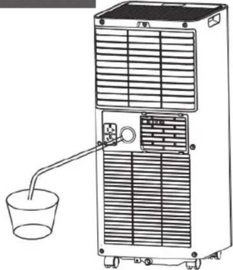
Continuous drainage
The self-evaporating system uses the collected water to cool the condenser coils for better efficient performance. It is no need to empty the drainage tank in cooling operation except in drying operation and high humidity conditions. The condensate water evaporates at the condenser and evacuated through the exhaust hose.
For continuous operation or unattended operating in drying operation, please connect the attached drain hose to the unit. Condensate water can be automatically flow into a bucket or drain by gravity.
■ Switch off the unit before operating.
■ Remove the plug of the water outlet opening, and keep it in safe area.
■ Securely and properly connect the drain hose and make sure it is not
ENGLISH
kinked and clear of obstruction.
■ Place the outlet of hose over a drain or bucket and ensure that water could freely flow out of the unit.
- Do not submerge the end of hose into water; otherwise it can cause “Air Lock” in the hose.
FIGURE N°14
To avoid water spillage:
■ As the negative pressure of condensate drain pan is large, tilt the drain hose downward toward the floor. It is appropriate that the degree of inclination should exceed 20 degrees.
■ Straighten the hose to avoid a trap existing in the hose
6. CLEANING AND CARE (every two weeks)
Dust collects on the filter and restricts the airflow. The restricted airflow reduces the efficiency of the system and if it becomes blocked it can cause damage to the unit.
The air filter requires regular cleaning. The air filter is removable for easy cleaning. Do not operate the unit without an air filter, or the evaporator may be contaminated.
- Press POWER button to switch off the unit and unplug the power cord.
- Remove the filter mesh from the unit.
- Use a vacuum cleaner to suck dust from the filter.
- Turn the filter over and rinse the air filter under running water. Let the water run through the filter in the opposite direction of air flow. Set aside and allow the filter to air dry completely before reinstalling.
Switch off the unit and remove the air filters.
Rinse the air filter under running water.
FIGURE N°15

Warning!!!
Do not touch the evaporator surface with bare-hand, or could
cause injury of your fingers.
6.2. CLEANING UP OF REFRIGERANT
General Measures:
- Gas/vapor heavier than air. May accumulate in confined spaces, particularly at or below ground level.
- Eliminate every possible source of ignition.
- Use appropriate personal protection equipment (PPE).
- Evacuate unnecessary personnel, isolate, and ventilate area.
- Do not get in eyes, on skin, or on clothing. Do not breathe vapors or gas.
- Prevent entry to sewers and public waters.
- Stop the source of the release, if safe to do so. Consider the use of water spray to disperse vapors.
- Isolate the area until gas has dispersed. Ventilate and gas test area before entering. Contact competent authorities after a spill.
7. TROUBLESHOOTING
Symptom Inspection Solution
| The unit is not operating. | Check the power connection in securely. | Insert the power cord securely into the wall Outlet. | |
| Check if the water level indicator lights up? | Empty the drain pan by remove the rubber plug. | ||
| Check the room temperature. | The range of operating temperature is 5-35°C. | ||
| The unit works with reduced capacity | Check the air filter for dirt Clean the air filter as necessary. | ||
| Check if the air duct is blocked. | To clear the obstacle. | ||
| Check if the room door or window is open. | Keep the door and windows closed. | ||
| Check if the desired operating mode is selected and the temperature is properly set. | Set the mode and temperature at proper set-point according the manual. (refer to STEP 4) | ||
| The exhaust hose is detached. | Make sure the exhaust hose is securely attached. | ||
| Water Leakage | Overflow while moving the unit. | Empty the water tank before transport. | |
| Check if the drain hose is kinked or bends. | Straighten the hose to avoid a trap existing. | ||
| Excessive Noise Check | Check if the unit is securely positioned. | Place the unit on horizontal and firm ground. | |
| Check if any loose, vibrating parts. | Secure and tight the parts. | ||
| Noise sounds like water flowing. | Noise comes from flowing refrigerant. This is normal. | ||
| Error Codes | E0 Com | Communication faults between main PCB and display PCB | Check the wire harness of the display PCB for damage. |
| E1 | Ambient temperature sensor failure | Check connection or replace it. To clean or replace the temperature sensor | |
| E2 | Coil temperature sensor failures. | Check connection or replace it. To clean or replace the temperature sensor. | |
| FT | Condensate water high level alarm. | Empty the drain pan by removal the rubber plug. | |
ENGLISH
8. DECOMMISSIONING
8.1. STORAGE
Long-Term Storage - If you will not be using the unit for an extended period of time (more than a few weeks) it is best to clean the unit and dry it out completely. Please store the unit per the following steps:
- Unplug the unit and remove exhaust hose and window kit store with the unit.
- Drain the remaining water from the unit.
- Clean the filter and let the filter dry completely in a shaded area.
- Re-install the filter at its position.
- The unit must be kept in upright position when in storage.
- Preserving the machine in ventilating, dry, non-corrosive gas and safe place indoor.
ATTENTION:
The evaporator inside the machine has to be dried out before the unit is packed to avoid component damage and molds. Unplug the unit and place it in a dry open area for days to dry it out. Another way to dry the unit is turn on the machine, adjust it to low-wind ventilation mode, and maintain this state until the drainage pipe becomes dry, so as to keep the inside of the body in a dry state and prevent it from mildewing.
8.2. DISPOSAL

WARNING!!!
Releasing refrigerant into atmosphere is strictly forbidden!
Do not dispose of electrical appliances as unsorted municipal waste, use separate collection facilities. Contact your local government for information regarding the collection systems available. If electrical appliances are disposed of in land-fills or dumps, hazardous substances can leak into the groundwater and get into the food chain, damaging your health and well-being.
9. WIFI CONNECTION
Information on the App "Smart Life"
The "Smart Life" app is available for android and iOS.
Scan the corresponding QR code to get directly to the download.

natural_image
Blue square icon with a white house and wireless signal symbol (no text or numbers)Download Smart Life App

Information on How to Use the App
This appliance allows you to operate the appliance via your home net-work. A prerequisite is a permanent WIFI connection to your router and the free app "Smart Life".
- Install the "Smart Life" app. Create a user account.
- Activate the WIFI function in the settings of your appliance.
- Place the appliance at a distance of about 5 meters to your router.
- As long as the power is turned on,
the WIFI indicator flashes. After 3 minutes, the status will be canceled if there is no network configuration, and the indicator light is off. If you need to re-connect the WIFI, long press the “timer” button for 5 Second to start the network configuration, the WIFI indicator flashes again.
WIFI Connected
■ Method 1
Connected via Bluetooth
Open the bluetooth of your mobile phone or other device.
When WIFI indicator flashes, open "Smart Life" APP, the unit will connected via bluetooth automatically.
■ Method 2
When WIFI indicator flashes, select "Add Device"- "Small Home Appliances"- "Dehumidifier", and follow the instructions on the display.
Check the status of the WIFI indicator and choose the correct status.
If the WIFI indicator flash rapidly, it can connected directly.
If the WIFI indicator flash slowly, press "Go to Connect" to connect the WIFI named "SmartLife-XXXX".
Remarks:
Once the appliance has been successfully connected, the WIFI lamp lights up. Now you can operate the appliance using the app.
Press and hold the Timer button for about 5 seconds, the appliance disconnect, the WIFI lamp lights off.
SPANISH
1. ANTES DE COMENZAR
natural_image
Icon of a house with wireless signal waves, no text or symbols presentDownload Smart Life App

natural_image
Blue gradient icon with a white house silhouette and wireless signal waves (no text or symbols)Download Smart Life App

1.1 DESCRIPTION DU PRODUIT
3. APERÇU DU PRODUIT
3.1 SCHÉMA DU PRODUIT
FIGURE 1 (À LA FIN DU LIVRE)
natural_image
Blue square icon with a white house and wireless signal symbol (no text or numbers)Download Smart Life App

natural_image
Blue gradient icon with a white house and wireless signal symbol (no text or numbers)Download Smart Life App

natural_image
Blue square icon with a white house and wireless signal symbol (no text or numbers)Download Smart Life App

natural_image
Blue gradient icon with a white house and wireless signal symbol (no text or numbers)Download Smart Life App

natural_image
Blue square icon with a white house and wireless signal symbol (no text or numbers)Download Smart Life App

1.1 DESCRIEREA PRODUSU- LUI
natural_image
Blue square icon with a white house and wireless signal symbol (no text or numbers)Download Smart Life App

natural_image
Blue square icon with a white house and wireless signal symbol (no text or numbers)Download Smart Life App

natural_image
Blue square icon with a white house and wireless signal symbol (no text or numbers)Download Smart Life App

The image contains no legible text or symbols.
תְרָה בְּרָה
2
BUNIONIF
Small Home Appli"ב"
The image contains no legible text or symbols. It is a graphical symbol (a stylized 'S' with a dot above it) and lacks any readable characters to extract. Therefore, no OCR output can be generated.
הַרְשָׁ
The image contains no legible text or characters. It is a graphical symbol resembling a stylized letter 'N' with a vertical line and a horizontal line, but lacks any textual content to extract. Therefore, no OCR output can be generated.
DRUMMER
תָרְשָׁ.
הכלה
The image contains no legible text or symbols. The characters are in standard script and do not correspond to any specific character or punctuation. Therefore, the correct OCR output is an empty string.
yahn's 10
TV SPEDD
הכלהה
,
[Unreadable]
תְפַרָה בְּרָה
upon
0172034
תְקּוֹתָה
n##DE
הכלה
nǐ yì
תְבָרִיֹתְה
תְפַרָה בְּרָה.
תָרְה בַרְה 17
y y z n
תְקָרִיָה בְּא
POMATO
nɔ .x
[Unreadable]
S.D.
תְּרָה, בְּרָה
The image contains no legible text or characters. It is a graphical symbol and cannot be accurately transcribed.
תָרִי
תְמַעֹרָה
The image contains no legible text or symbols. The OCR result "2018" is a hallucination and does not correspond to any content in the source image. Therefore, the correct OCR output is an empty string.
12
Bav.n
[Unreadable]
甲
אַתְּוֹתָה
תְרָה בְּרָה 17
תְרָה בְּרָה בְּרָה
תְקּוֹן, λ
הכלה
הכלה
תְרָה בַל.
κν 190.
הַעְרָה.
.
图2.1
הַרְשָׁהִי!
HEBREW
בַלְרָה אַתְאָה
vnd2
iTn
תְבָרִי
CPONER
תְקּרָה
n'pMDE
The image contains no legible text or characters. It is a graphical symbol (a stylized 'N' with a dot above it) and lacks any readable text to extract. Therefore, no OCR output can be generated.
DPMER
NS.
תְבָרִי אַלְאָה
m
G
הַרְשָׁ
prktn
The image contains no legible text or characters. It is a graphical symbol and cannot be accurately transcribed.
תְפַרָה בְּשִׁים
DE
תְּרָה
תְאָהִיַעֹן
תְּרָה בְּרָה
הַרְשָׁה, בְּבָר
הכלה
yahn'10
TYI
The image contains no legible text or symbols.
תְפַרָה בְּשָׁ
p
D17000
תְקַעָה
DE
הכלה
nǐ yì yì
תְקּרָה בְּרָה
תְׁרָה בְּרָה.
תָרְה בַרְה 17
.4n
npr.
The image contains no legible text or symbols. It is a graphical symbol (a pixelated graphic) and cannot be accurately transcribed as standard OCR text. Therefore, no valid OCR output can be generated from this image.
900
הכלה
ビナロ 3
4.3
The image contains no legible text or symbols.
B0115
Dum.
תְבָרִיּ
,
The image contains no legible text or characters. It is a graphical symbol (a stylized letter 'D' with a horizontal line and vertical line) and cannot be accurately transcribed as standard OCR content. Therefore, no valid OCR text can be generated that matches the visual content of the source image.
[No text detected]
תְבָרִי:1
The image contains no legible text or symbols.
D
12
הכלה
The image contains no legible text or symbols. It is a graphical design and does not contain any readable characters, letters, or punctuation. Therefore, no OCR output can be generated.
תְבָרִיּ
7
תְרָה בְּרָה
1502140
.תְּבָר

B
תְּלָה
אַלְרָה
אַתְרָה
תְבָרִי בְּשָׁה
Authority
The image contains no legible text or symbols.
תְבָרִיּה
תַעָה:

[Unreadable]
תְּבָרִי, בְּשַׁ
תְּוֹתָה
תְמָרִי
[Unreadable]
.
127
[NO TEXT]
בַרְשָׁה
The image contains no legible text or symbols. According to Rule 4 (Edge Noise Strategy), since the ground truth is not clearly visible, OCR should not output any character. Therefore, the corrected OCR text is:
[No legible text]
T
שְׁרָה בְּרָה
2019年
[Unreadable]
הכלה
图四
17回
natural_image
Cylindrical object with textured surface, no visible text or symbols2
3
natural_image
Pure diagram of two overlapping circular components with no text or symbols4
5

natural_image
Simple line drawing of a curved pipe with an upward arrow indicating direction (no text or symbols)6

natural_image
Simple gray rectangular button with a white oval on the right side (no text or symbols)ONLY FOR SETSUAIR PAC-10000PH
FIGURA 3
natural_image
Illustration of a portable air conditioner unit with a truck and distance annotation (r=50cm), no text or symbols present.FIGURA 6
natural_image
Diagram showing three vertical cylindrical objects labeled A, B, and a separate cylindrical object with an arrow indicating direction (no text or symbols present)FIGURA 8
natural_image
Line drawing of a large industrial air conditioning unit with ventilation grilles and a central cylindrical component (no text or symbols)FIGURA 4
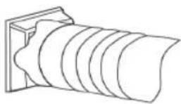
FIGURA 5
natural_image
Diagram of a coiled spring with a flanged end and rotation arrow (no text or symbols)FIGURA7
natural_image
Illustration of a window with a hose and directional arrow, no text or symbols presentFIGURA 9
natural_image
Line drawing of an air conditioner unit with a curved hose, placed near a window (no text or symbols)FIGURA 10
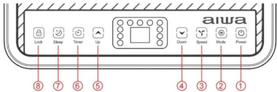
FIGURA 11
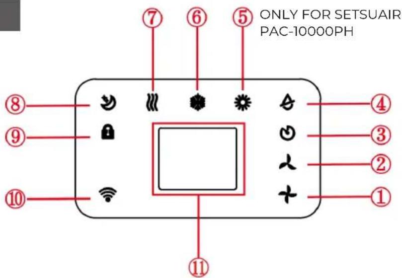
FIGURA 12
YUKIAIR PAC-10000P
SETSUAIR PAC-10000PH
FIGURA 13
natural_image
Line drawing of a dual-chamber industrial air conditioner unit with ventilation grilles and control panel (no text or symbols)FIGURA 14
natural_image
Line drawing of a portable air conditioner unit with a cup and cooling unit (no text or symbols)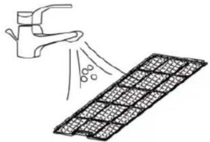
natural_image
Illustration of a hand spraying water onto a grid-patterned surface (no text or symbols)NOTES
NOTES
aiwa®
YUKIAIR PAC-10000P | SETSUAIR PAC-10000PH
www.aiwa-industries.com
All Pictures shown are for illustration purpose only.
All Rights Reserved. All other trademarks are property of their respective owners.
All specifications are subject to change without prior notice.
Aiwa Europe S.L., Av. Siglo XXI, 34, ES-08840.
REV. 02/02/2024 V1