FUJINAIR 9 ACD-9100 - Air Conditioning AIWA - Free user manual and instructions
Find the device manual for free FUJINAIR 9 ACD-9100 AIWA in PDF.

User questions about FUJINAIR 9 ACD-9100 AIWA
0 question about this device. Answer the ones you know or ask your own.
Ask a new question about this device
Download the instructions for your Air Conditioning in PDF format for free! Find your manual FUJINAIR 9 ACD-9100 - AIWA and take your electronic device back in hand. On this page are published all the documents necessary for the use of your device. FUJINAIR 9 ACD-9100 by AIWA.
USER MANUAL FUJINAIR 9 ACD-9100 AIWA
ROOM AIR CONDITIONER INSTALLATION MANUAL
natural_image
Line drawing of a Siemens air conditioner unit with fan grille and control panel (no text or symbols on body)AIWA HaruAir Series AIWA FūjinAir Series AIWA KazéAir Series
- Please read this manual carefully before installation. This appliance is filled with R32. Keep this operation manual for future reference. Manufactured: RPC Engineering in Japan
Contents
Warning 1
Loading and Unloading/Transporting Management/Storage Requirements....3
Installation Instructions....3
Relocation Procedures....7
Maintenance Instructions....7
Scrapping and Recovery....10
Indoor/Outdoor Unit Installation Drawings.... 12
Safety Precautions ......13
Read Before Installation....17
Installation Procedure....20
Outdoor Unit Troubleshooting....25

Read the precautions in this manual carefully before operating the unit.
This appliance is filled with R32.
Keepthismanualwheretheusercaneasilyndit.fi

WARNING:
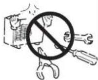
▲Ask your dealer or qualified personnel to carry out installation work. Do not attempt to install the air conditioner yourself. Improper Installation may result in water leakage, electric shocks, fire or explosion.
▲Install the air conditioner in accordance with the instructions in this installation manual
▲Be sure to use only the specified accessories and parts for installation work.
▲ Install the air conditioner on a foundation strong enough to withstand the weight of the unit.
▲Electrical work must be performed in accordance with relevant local and national regulations and with instructions in this installation manual, Be sure to use a dedicated power supply circuit only. The wiring method should be in line with the local wiring standard. The type of connecting wire is H07RN-F.
▲ Use a cable of suitable length, Do not use tapped wires or an extension lead as this may cause overheating, electric shocks, fire or explosion.
▲ All the cables shall have got the European authentication certificate. During installation, when the connecting cables break off, it must be assured that the grounding wire is the last one to be broken off.
▲ If refrigerant gas leaks during installation, ventilate the area immediately.oxic gas may be produced if the refrigerant comes into contact with fire, and explosion may be happen.
▲After completing installation, check for refrigerant gas leakage
▲When installing or relocating the air conditioner, be sure to bleed the refrigerant circuit to ensure it is free of air, and use only the specified refrigerant (R32).
▲Make sure ground connection is correct and reliable. Do not earth the unit to a utility pipe, lightning conductor or telephone earth lead. Imperfect earthing may result in electric shocks.
▲Be sure to install an earth leakage circuit explosion-proof breaker.
▲ The breaker of the air conditioner should be all-pole switch and explosion-proof. The distance between its two contacts should not be no less than 3mm. Such means for disconnection must be incorporated in the wiring.
▲ Do not use means to accelerate the defrosting process or to clean, other than those recommended by the manufacturer.
▲The appliance must be stored in a room without continuously operating ignition sources, the radius of the storage area should be no less than 2.5 m (for example: open flames, an operating gas appliance or an operating electric heater).
▲Do not pierce or burn.
▲Be aware that refrigerants may not contain an odour.
▲The appliance must be installed, operated and stored in a room with a floor area larger than 3m^2 .
The room should be well ventilated.
▲ Comply with national gas regulations.
▲This appliance can be used by children aged 8 years and above and persons with reduced physical, sensory or mental capabilities or lack of experience and knowledge if they have been given supervision or instruction concerning use of the appliance in a safe way and understand the hazards involved. Children shall not play with the appliance. Cleaning and user maintenance shall not be made by children without supervision.
▲The air conditioner can not be discarded or scrapped Randomly. If you need please contact customer service personnel of Haier to scrap in order to obtain the correct disposal methods.
▲Reusable mechanical connectors and flared joints are not allowed indoor.

CAUTION:
Do not install the air conditioner at any place where there is danger of flammable gas leakage. In the event of a gas leakage, build-up of gas near the air conditioner may cause a fire to break
▲ Tighten the flare nut according to the specified method such as with a torque wrench. If the flare nut is too tight, it may crack after prolonged use, causing refrigerant leakage.
▲ Take adequate steps to prevent the outdoor unit being used as a shelter by small animals. Small animals making contact with electrical parts can cause malfunctions, smoke or fire.
▲ Please instruct the customer to keep the area around the unit clean
The temperature of refrigerant circuit will be high, please keep the inter-unit wire away from copper pipes that not thermally insulated.
▲ Only qualified personnel can handle, fill, purge and dispose of the refrigerant.
If the unit is installed in coastal areas or other regions with sulfate gas of salty atmosphere, corrosion will occur and the unit service life will be shortened.
EUROPEAN REGULATIONS CONFORMITY FOR THE MODELS
Climate:T1 Voltage:230V
CE
All the products are in conformity with the following European provision:
- 2014/53/EU(RED)
- 2014/517/EU(F-GAS)
- 2009/125/EC(ENERGY)
- 2010/30/EU(ENERGY)
- 2006/1907/EC(REACH)
RoHS
The products are fulfilled with the requirements in the directive 2011/65/EU of the European parliament and of council on the Restriction of the use of Certain Hazardous Substances in Electrical and Electronic Equipment (EU RoHS Directive)
WEEE
In accordance with the directive 2012/19/EU of the European parliament, herewith we inform the consumer about the disposal requirements of the electrical and electronic products.
DISPOSAL REQUIREMENTS:
Your air conditioning product is marked with this symbol. This means that electrical and electronic products shall not be mixed with unsorted household waste. Do not try to dismantle the system yourself: the dismantling of the air
conditioning system, treatment of the refrigerant, of oil and of other part must be done by a qualified installer in accordance with relevant local and national legislation. Air conditioners must be treated at a specialized treatment facility for reuse, recycling and recovery. By ensuring this product is disposed of correctly, you will help to prevent potential negative consequences for the environment and human health. Please contact the installer or local authority for more information. Battery must be removed from the remote controller and disposed of separately in accordance with relevant local and national legislation.
Wi-Fi
-Wireless maximum transmit power (20dBm)
-Wireless operating frequency range (2400\~2483.5MHz)
IMPORTANT INFORMATION REGA- RDING THE REFRIGERANT USED
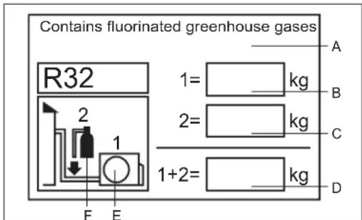
This product contains fluorinated greenhouse gases.
Do not vent into the atmosphere.
Refrigerant type: R32
GWP* value=675
GWP=global warming potential
Please fill in with indelible ink,
• 1 the factory refrigerant charge of the product
• 2 the additional refrigerant amount charged in the field and
• 1+2 the total refrigerant charge
on the refrigerant charge label supplied with the product. The filled out label must be adhered in the proximity of the product charging port (e.g. onto the inside of the stop value cover).
A contains fluorinated greenhouse gases
B factory refrigerant charge of the product: see unit name plate
C additional refrigerant amount charged in the field
D total refrigerant charge
E outdoor unit
F refrigerant cylinder and manifold for charging
The values of CO_2 equivalent are shown in Table 1
Loading and Unloading/Transporting Management/Storage Requirements
- Loading and Unloading Requirements
1) The products shall be carefully handled during loading and unloading.
2) Rude and barbarous handling such as kicking, throwing, dropping, bumping, pulling and rolling is not allowed.
3) The workers engaged in loading and unloading must be subject to necessary trainings on the potential hazards caused by barbarous handling.
4) Dry powder extinguishers or other suitable fire extinguishing apparatus within the period of validity shall be equipped at the loading and unloading site.
5) The untrained personnel cannot be engaged in loading and unloading of flammable refrigerants air conditioner.
6) Before loading and unloading, anti-static measures shall be taken, and phones cannot be answered during loading and unloading.
7) Smoking and open fire are not allowed around the air conditioner.
• Transporting Management Requirements
1) The maximum transporting volume of finished products shall be determined as per local regulations.
2) The vehicles used for transporting shall be operated as per local laws and regulations.
3) Dedicated after-sales vehicles shall be used for maintenance, and exposed transporting of refrigerant cylinders and the products to be maintained is not allowed.
4) The rain cover or similar shielding material of transporting vehicles shall be provided with certain flame retardancy.
5) Leakage warning device of flammable refrigerant shall be installed inside the closed-type compartment.
6) Anti-static device shall be equipped inside the compartment of transporting vehicles.
7) Dry powder extinguishers or other suitable fire extinguishing apparatus within the period of validity shall be equipped inside the driver's cab.
8) Orange-white or red-white reflective stripes shall be pasted on the sides and tail of the transporting vehicles, to remind the vehicles behind of keeping distance.
9) The transporting vehicles shall run at a constant speed, and heavy acceleration/deceleration shall be avoided.
10) Combustibles or the static articles cannot be transported simultaneously.
11) High-temperature area shall be avoided during transporting, and necessary radiating measures shall be taken in case the temperature inside the compartment is too high.
• Storage Requirements
1) The storage package of equipment used shall be such that no leakage of refrigerant will be caused due to mechanical damage of the equipment inside.
2) The maximum quantity of the equipment allowed to be stored together shall be determined as per local regulations.
Installation Instructions
• Installation Precautions
WARNING!
The area of the room in which R32 refrigerant air conditioner is installed cannot be less than the minimum area specified in the table below, to avoid potential safety problems due to out-of-limit of refrigerant concentration inside the room caused by leakage of refrigerant from refrigeration system of the indoor unit.
★ Once the horn mouth of connecting lines is fastened, it may not be used again (the air tightness may be affected).
★ A whole connector wire shall be used for indoor/outdoor unit as required in the operation specification of installation process and operation instructions.
The values of The maximum refrigerant charge amount are shown in table 2
Minimum Room Area
| Type | LFL kg/m^3 | Total Mass Charged/ kg Minimum Room Area/ m^2 | |||||
| R32 | 0.307 | 1.781 | 2.519 | 3.708 | 4.932 | 6.170 | 7.965 |
| 3 | 6 | 13 | 23 | 36 | 60 | ||
• Safety Awareness
- Procedures: operation shall be made as per controlled procedures to minimize the probability of risks.
-
Area: area shall be divided and isolated appropriately, and operation in an enclosed space shall be avoided. Before the refrigeration system is started or before hot working, ventilation or opening of the area shall be guaranteed.
-
Site inspection: the refrigerant shall be checked.
-
Fire control: the fire extinguisher shall be placed nearby, and fire source or high temperature is not allowed; the sign of "No smoking" shall be arranged.
• Unpacking Inspection
-
Indoor unit: nitrogen is sealed during the delivery of indoor units (inside the evaporator), and the red sign at the top of the green plastic seal cap on the evaporator air pipes of the indoor unit shall be checked first after unpacking. In case the sign is raised, the nitrogen sealed still exists. Afterwards, the black plastic seal cap at the joint of evaporator liquid pipes of the indoor unit shall be pressed, to check whether nitrogen still exists. In case no nitrogen is sprayed out, the indoor unit is subject to leakage, and installation is not allowed.
-
Outdoor unit: the leak detection equipment shall be extended into the packing box of the outdoor unit, to check whether the refrigerant is leaking. If the refrigerant leakage is identified, installation is not allowed, and the outdoor unit shall be delivered to the maintenance department.
• Inspection on Installation Environment
- The room area checked cannot be less than the area specified on the warning sign of the indoor unit.
- Inspection on the surrounding environment of place of installation: the outdoor unit of flammable refrigerants air conditioner cannot be installed inside an enclosed room reserved.
- Power supply, switches or other high-temperature articles such as the fire source and oil heater shall be avoided below the indoor unit.
- The power supply shall be provided with earthing wire and be reliably earthed.
- While punching the wall with an electric drill, whether embedded water/electricity/gas pipelines are designed at the hole preset by the user shall be verified in advance. It is recommended that the through-wall holes reserved shall be used as much as possible.
• Safety Principles of Installation
- Favorable ventilation shall be maintained at the place of installation (doors and windows are opened).
- Open fire or high-temperature heat source (including welding, smoking and oven) higher than 548°C is not allowed within the scope of flammable refrigerant.
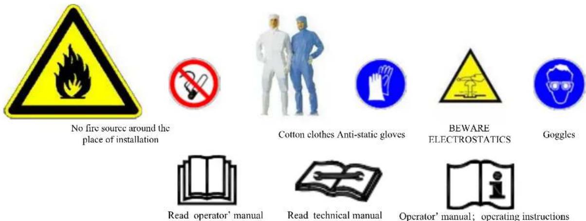
- Anti-static measures shall be taken, such as the wearing of cotton clothes and cotton gloves.
- The place of installation shall be convenient for installation or maintenance, and cannot be adjacent to heat source and flammable and combustible environment.
- In case of refrigerant leakage of the indoor unit during installation, the valve of the outdoor unit shall be closed immediately, and windows shall be opened, and all the personnel shall be evacuated. After the leakage of refrigerant is handled, the indoor environment shall be subject to concentration detection. Further handling is not allowed until the safety level is reached.
- In case the product is damaged, it must be delivered to the maintenance point. Welding of refrigerant pipelines at the user's site is not allowed.
- The installation position of air conditioner shall be convenient for installation or maintenance. Barriers shall be avoided around the air inlet/outlet of the indoor/outdoor unit, and the electrical appliance, power switches, sockets, valuables and high-temperature products within the scope of both sidelines of the indoor unit shall be avoided.
• Electrical Safety Requirements
Note:
- The surrounding conditions (ambient temperature, direct sunlight and rainwater) shall be noticed during electrical wiring, with effective protective measures being taken.
- Copper wire cable in line with local standards shall be used as the power line and connector wire.
- Both the indoor unit and outdoor unit shall be reliably earthed.
- Wiring for the outdoor unit shall be made first and then the indoor unit. The air conditioner can only be powered on after wiring and pipe connection.
- The dedicated branch circuit must be used, and leakage protector with sufficient capacity must be installed.
• Qualification Requirements of Installer
Relevant qualification certificate must be obtained as per national laws and regulations.
- Indoor Unit Installation
1. Fixation of wall panel and piping layout
In case of left/right water pipe connection for the indoor unit, or in case the evaporator interface of the indoor unit and the horn mouth of the connecting piping cannot be extended to the outdoor side for installation, the connector pipes shall be connected to the evaporator piping interface of the indoor unit in the process of horn mouth.
2. Piping layout
During layout of connecting pipes, drain hose and connector wires, the drain hose and connecting wire shall be placed at the bottom and top respectively. The power line cannot be twined with the connector wire. The drain pipes (especially inside the room and machine) must be winded with thermal insulation materials.
3. Nitrogen charging for pressure maintaining and leak detection
After the evaporator of the indoor unit is connected to the connector pipe (after welding), nitrogen more than 4.0MPa shall be charged inside the evaporator and the piping connected to evaporator with a nitrogen cylinder (adjusted by a reducing valve). Afterwards, the valve of the nitrogen cylinder shall be closed, for leak detection with soapy water or leak detecting solution. The pressure shall be maintained for more than 5 minutes, and then whether the system pressure is reduced or not shall be observed. In case the pressure is reduced, leakage can be identified. After the leak point is handled, the steps above shall be repeated.
After the evaporator of the indoor unit is connected to connecting piping, nitrogen shall be charged for pressure maintaining and leak detection. Afterwards, the evaporator shall be connected to the two-way stop valve and three-way stop valve of the outdoor unit. After the copper cap of the connecting piping is fastened, nitrogen more than 4.0MPa shall be charged at the access hole of the three-way stop valve with a charging hose. The valve of the nitrogen cylinder shall be closed, for leak detection with soapy water or leak detecting solution. The pressure shall be maintained for more than 5 minutes, and then whether the system pressure is reduced or not shall be observed. In case the pressure is reduced, leakage can be identified. After the leak point is handled, the steps above shall be repeated.
The operation above can also be completed after the indoor unit is connected to the connecting pipelines and the two-way stop valve and three-way stop valve of the outdoor unit, after the access hole of the outdoor unit is connected to the nitrogen cylinder and pressure gauge and after more than 4.0MPa nitrogen is charged. No leak points are identified in the leak detection at the joint/welding junction of the indoor unit and at the joint of connecting pipelines of the two-way stop valve and three-way stop valve of the outdoor unit. It must be guaranteed that each joint is available for leak detection during installation.
The next step (vacuumizing with a vacuum pump) can only be continued after the installation steps (nitrogen charging for pressure maintaining and leak detection normal) are completed.
• Outdoor Unit Installation
1. Fixation and connection
Note:
a) Fire source shall be avoided within 3m around the place of installation.
b) The leak detection equipment of refrigerant shall be placed at a low position in the outdoor, and shall be opened.
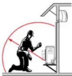
natural_image
Illustration of a person kneeling at a desk near a security camera (no text or symbols present)1) Fixation
The support of the outdoor unit shall be fixed onto the wall surface, and then the outdoor unit shall be fixed onto the support horizontally. In case the outdoor unit is wall-mounted or roof-mounted, the support shall be firmly fixed, to avoid the damage of strong wind.
2) Installation of connecting pipes
The cone of the connecting pipes shall be aligned with the conical surface of corresponding valve connector. The nut of connecting pipes shall be installed at a proper position and then be tightened with a spanner. Excessive tightening torque shall be avoided, or otherwise the nut may be damaged.
- Vacuumizing
A digital vacuum gauge shall be connected for vacuumizing. The duration of vacuumizing shall be at least 15 minutes, and the pressure of the vacuum gauge shall be below 60Pa. Afterwards, the vacuumizing equipment shall be closed, and whether the reading of the digital vacuum gauge is increased or not shall be observed after the pressure is maintained for 5 minutes. In case no leakage is identified, the two-way stop valve and three-way stop valve of the outdoor unit may be opened. Finally, the vacuumizing hose connected to the outdoor unit can be disassembled.
- Leak Detection
The joint of connecting pipes for the outdoor unit shall be subject to leak detection with soap bubble or dedicated leak detection equipment.
• Post-installation Inspection Items and Test Run
Post-installation Inspection Items
| Items to Be Checked Consequence of Improper Installation | |
| Whether the installation is firm or not The unit may | fall, vibrate or make a noise |
| Whether the inspection on air leakage is completed | The refrigerating capacity (heating capacity) may be insufficient |
| Whether the unit is fully insulated Condensation or | drip may occur |
| Whether the drainage is smooth or not Condensation | or drip may occur |
| Whether the power voltage is identical to that marked on the nameplate | Failure may occur or the parts may be burned |
| Whether the circuit and pipeline are installed correctly | Failure may occur or the parts may be burned |
| Whether the unit is safely earthed Electric leakage may occur | |
| Whether the type of wire is in line with relevant regulations | Failure may occur or the parts may be burned |
| Whether barriers are identified at the air inlet/outlet of the indoor/outdoor unit | The refrigerating capacity (heating capacity) may be insufficient |
| Whether the length of refrigerant pipes and the refrigerant amount charged are recorded | The refrigerant amount charged cannot be confirmed |
Test Run
1. Preparations
(1) Power on is not allowed before all the installation operations are completed and before the leak detection is proven qualified.
(2) The control circuit shall be connected correctly and all the wires shall be firmly connected.
(3) The two-way stop valve and three-way stop valve shall be opened.
(4) All the scattered articles (especially the metal filing and thread residue) shall be removed from the unit body.
2. Methods
(1) Switch on the power supply and press the “ON/OFF” on the remote controller, after which the air conditioner will start operating.
(2) Press “Mode” to select refrigeration, heating and sweeping wind, and observe whether the air conditioner is under normal operation.
Relocation Procedures
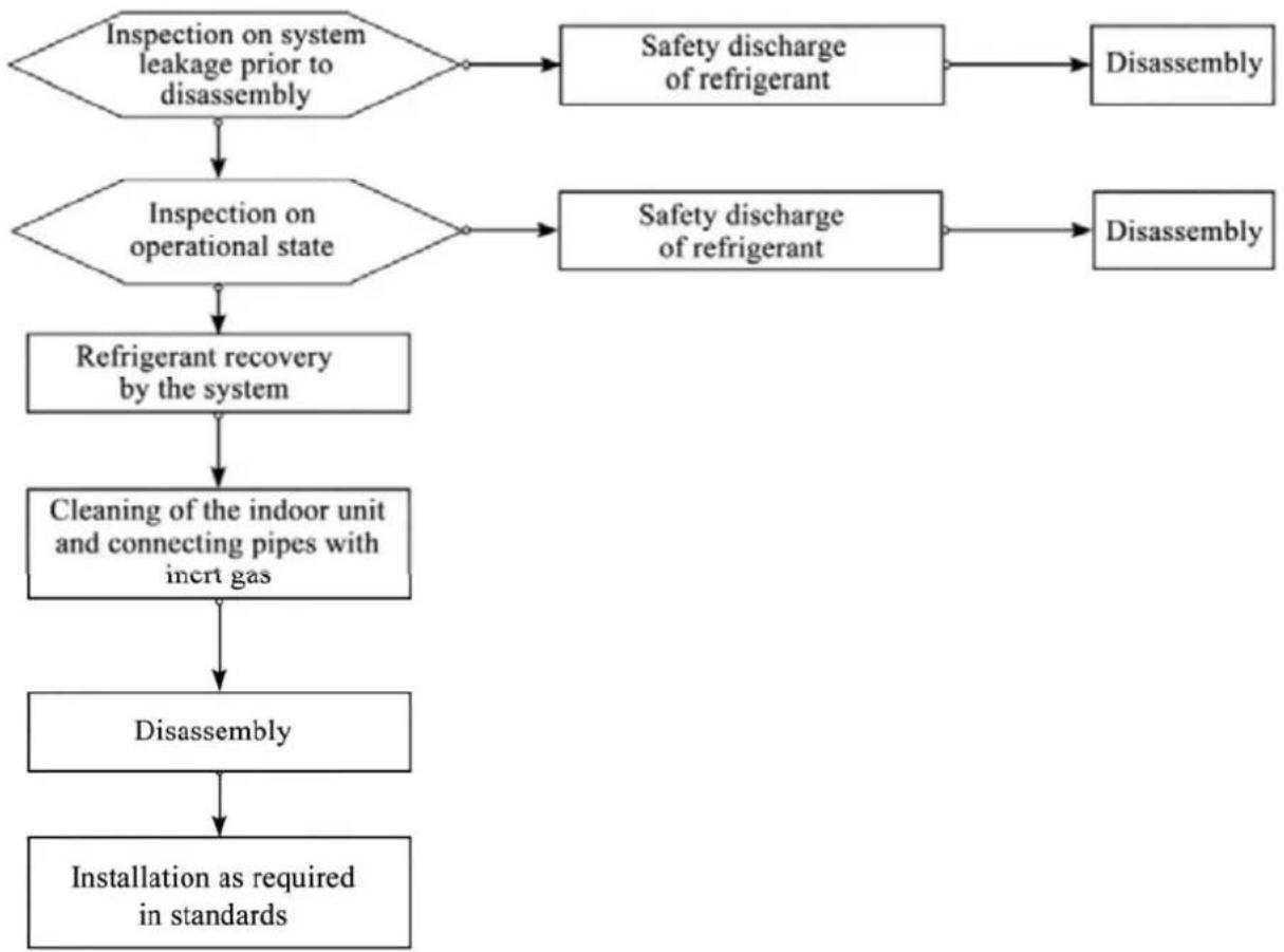
flowchart
graph TD
    A["Inspection on system leakage prior to disassembly"] --> B{Inspection on operational state}
    B --> C["Refrigerant recovery by the system"]
    C --> D["Cleaning of the indoor unit and connecting pipes with incrt gas"]
    D --> E["Disassembly"]
    E --> F["Installation as required in standards"]
    B --> G["Safety discharge of refrigerant"]
    G --> H["Disassembly"]
    B --> I["Safety discharge of refrigerant"]
    I --> J["Disassembly"]
Note: in case relocation is required, the joint of evaporator gas/liquid pipes of the indoor unit shall be cut off with a cutting knife. Connection is only allowed after re-flaring (the same to the outdoor unit).
Maintenance Instructions
Maintenance Precautions
Precautions
- For all the faults requiring welding the refrigeration pipelines or components inside the refrigeration system of R32 refrigerant air conditioners, maintenance at the user's site is never allowed.
- For the faults requiring radical disassembly and bending operation of the heat exchanger, such as the replacement of the outdoor unit chassis and integral disassembly of the condenser, inspection and maintenance at the user's site are never allowed.
- For the faults requiring replacement of the compressor or parts & components of refrigeration system, maintenance at the user's site is not allowed.
- For other faults not involved in the refrigerant container, internal refrigeration pipelines and refrigeration elements, the maintenance at the user's site is allowed, including the cleaning and dredging of the refrigeration system requiring no disassembly of refrigeration elements and no welding.
- In case replacement of gas/liquid pipes is required during maintenance, the joint of evaporator gas/liquid pipes of the indoor unit shall be cut off with a cutting knife. Connection is only allowed after re-flaring (the same to the outdoor unit).
Qualification Requirements of Maintenance Personnel
- All the operators or the maintenance personnel involved in refrigerating circuits shall be provided with the effective certificate issued by an industry-accepted assessment institute, to ensure that they are qualified for safety disposal of refrigerant as required in the assessment regulations.
- The equipment can only be maintained and repaired as per the method recommended by the manufacturer. In case the assistance from personnel of other disciplines is required, the assistance shall be supervised by the personnel with qualification certificate involved in flammable refrigerant.
Inspection on Maintenance Environment
- Before operation, the refrigerant leaked in the room is not allowed.
- The area of the room in which maintenance is made shall be in line with the nameplate.
• Continuous ventilation shall be maintained during maintenance. - Open fire or high-tem perature heat source higher than 548 degree which can easily give birth to open fire is not allowed inside the room within the maintenance area.
- During maintenance, the phones and the radioactive electronics of all the operators inside the room must be powered off.
• One dry powder or carbon dioxide extinguisher shall be equipped inside the maintenance area, and the extinguisher must be under available state.
Maintenance Site Requirements
- The maintenance site shall be provided with favorable ventilation and must be flat. Arrangement of the maintenance site inside the basement is not allowed.
- Welding zone and non-welding zone shall be divided at the maintenance site, and shall be clearly marked. A certain safety distance must be guaranteed between the two zones.
- Ventilators shall be installed at the maintenance site, and exhaust fans, fans, ceiling fans, floor fans and dedicated exhaust duct can be arranged, to meet the requirements of ventilation volume and uniform exhaust, and to avoid accumulation of refrigerant gas.
- Leak detection equipment for flammable refrigerant shall be equipped, with relevant management system being established. Whether the leak detection equipment is under available state shall be confirmed before maintenance.
- Sufficient dedicated vacuum pumps of flammable refrigerant and refrigerant charging equipment shall be equipped, with relevant management system for maintenance equipment being established. It shall be guaranteed that the maintenance equipment can only be used for vacuumizing and charging of one type of flammable refrigerant, and mixed usage is not allowed.
- The master power switch shall be arranged outside the maintenance site, with protective (anti-explosive) device being equipped.
- Nitrogen cylinders, acetylene cylinders and oxygen cylinders shall be placed separately. The distance between the gas cylinders above and the working area involved in open fire shall be at least 6m. The anti-backfire valve shall be installed for the acetylene cylinders. The color of the acetylene cylinders and oxygen cylinders installed shall meet the international requirements.
- The warning sign of "No Fire" shall be arranged inside the maintenance area.
- Fire control device suitable for electric appliance such as the dry powder extinguisher or carbon dioxide extinguisher shall be equipped, and shall always be under the available state.
- The ventilator and other electrical equipment at the maintenance site shall be relatively fixed, with standardized pipe routing. Temporary wires and sockets at the maintenance site are not allowed.
Leak Detection Methods
- The environment in which the refrigerant leakage is checked shall be free from potential ignition source. Leak detection with halogen probes (or any other detector with open fire) shall be avoided.
- For the system containing flammable refrigerant, leak detection may be realized with electronic leak detection equipment. During leak detection, the environment in which the leak detection equipment is calibrated shall be free from refrigerant. It shall be guaranteed that the leak detection equipment will not become potential ignition source, and is applicable to the refrigerant to be detected. Leak detection equipment shall be set at a percentage of the LFL of the refrigerant and shall be calibrated to the refrigerant employed, and the appropriate percentage of gas (25 % maximum) is confirmed.
- The fluid used for leak detection shall be applicable to most of the refrigerant. The use of chlorine-containing solvent shall be avoided, to avoid chemical reaction between chlorine and refrigerant and corrosion to copper pipelines.
- In case leakage is suspected, the open fire at the site shall be evacuated or be put out.
- In case welding is required at the leakage position, all the refrigerants shall be recovered, or be isolated at a position far from the leak point with a stop valve. Before and during welding, the whole system shall be purified with OFN.
Safety Principles
- During product maintenance, favorable ventilation shall be guaranteed at the maintenance site, and the close of all the doors/windows is not allowed.
- Operation with open fire is not allowed, including welding and smoking. The use of phones is also not allowed. The user shall be informed that cooking with open fire is not allowed.
- During maintenance in a dry season, when the relative humidity is less than 40% , anti-static measures shall be taken, including the wearing of cotton clothes and cotton gloves.
- In case the leakage of flammable refrigerant is identified during maintenance, forced ventilation measures shall be taken immediately, and the source of leak shall be plugged.
- In case the product damaged must be maintained by disassembling the refrigeration system, the product must be delivered to the maintenance point. Welding of refrigerant pipelines at the user's site is not allowed.
• During maintenance, in case re-treatment is required due to lack of fittings, the air conditioner shall be reset.
• The refrigeration system must be safely earthed in the whole course of maintenance. - For the door-to-door service with refrigerant cylinders, the refrigerant charged inside the cylinder cannot exceed the specified value. The cylinder placed in vehicles or at the installation/maintenance site shall be fixed perpendicularly and be kept away from heat sources, ignition source, source of radiation and electric appliance.
Maintenance Items
Maintenance Requirements
- Before the refrigeration system is operated, the circulating system shall be cleaned with nitrogen. Afterwards, the outdoor unit shall be vacuumized, the duration of which cannot be less than 30 minutes. Finally, 1.5\~2.0MPa OFN shall be used for nitrogen flushing (30 seconds\~1 minute), to confirm the position requiring treatment. Maintenance of the refrigeration system is only allowed after the residual gas of flammable refrigerant is removed
- During the use of refrigerant charging tools, cross contamination of different refrigerants shall be avoided. The total length (including the refrigerant pipelines) shall be shortened as much as possible, to reduce the residual of refrigerant inside.
- The cylinders of refrigerant shall be kept upright, and be fixed.
- Before refrigerant charging, the refrigeration system shall be earthed.
- The refrigerant charged shall be of the type and volume specified on the nameplate. Excessive charging is not allowed.
• After maintenance of the refrigeration system, the safety with a safe manner.
• The maintenance in progress shall not damage or lower the original class of safety protection of the system.
Maintenance of Electrical Components
- Partial of the electrical component under maintenance shall be subject to inspection on refrigerant leakage with dedicated leak detection equipment.
• After the maintenance, the components with safety protection functions cannot be disassembled or removed. - During the maintenance of sealing elements, before opening the seal cover, the air conditioner shall be powered off first. When power supply is required, continuous leak detection shall be carried out at the most dangerous position, to avoid potential risks.
- During maintenance of electrical components, the replacement of enclosures shall not affect the level of protection.
• After maintenance, it shall be guaranteed that the sealing functions will not be damaged or the sealing materials will not lose the function of preventing the entry of flammable gas due to aging. The substitute components shall meet the recommended requirements of the air conditioner manufacturer.
Maintenance of Intrinsically Safe Elements
The intrinsically safe element refers to the components working continuously inside flammable gas without any risks.
- Before any maintenance, leak detection and inspection on earthing reliability of the air conditioner must be carried out, to ensure no leakage and reliable earthing.
- In case the allowable voltage and current limit may be surpassed during the service of the air conditioner, any inductance or capacitance cannot be added in the circuit.
- Only the elements appointed by the air conditioner manufacturer can be used as the parts and components replaced, or otherwise a fire may be triggered in case of refrigerant leakage.
- For the maintenance not involved in system pipelines, the system pipelines shall be well protected, to ensure that no leakage will be caused due to maintenance.
• After maintenance and before test run, the air conditioner must be subject to leak detection and inspection on earthing reliability with leak detection equipment or leak detecting solution. It shall be guaranteed that the startup inspection is carried out without leakage and under reliable earthing.
Removal and Vacuumizing
The maintenance or other operations of the refrigeration circuit shall be made as per conventional procedures. Moreover, the flammability of refrigerant shall also be mainly considered. The following procedures shall be followed:
• Refrigerant clearing;
• Pipeline purification with inert gas;
- Vacuumizing;
• Pipeline purification again with inert gas;
- Pipeline cutting or welding. The refrigerant shall be recovered to a proper cylinder. The system shall be purged with OFN, to ensure safety. The step above may need to be repeated for several times. Compressed air or oxygen cannot be used for purging.
In the course of purging, OFN shall be charged inside the refrigeration system under vacuum state, to reach the operating pressure. Afterwards, the OFN shall be discharged to the atmosphere. Finally, the system shall be vacuumized. The step above shall be repeated until all the refrigerants in the system are cleared. The OFN charged for the last time shall be discharged to the atmosphere. Afterwards, the system can be welded. The operation above is necessary in case of pipeline welding.
It shall be guaranteed that no alight fire source is around the outlet of the vacuum pump and the ventilation is favorable.
Welding
- Favorable ventilation must be guaranteed in the maintenance area. After the maintenance machine is subject to the vacuumizing above, the system refrigerant can be discharged on the outdoor unit side.
- Before the outdoor unit is welded, it must be guaranteed that no refrigerant is inside the outdoor unit and the system refrigerant has been discharged and cleared.
- The refrigeration pipelines cannot be cut with a welding gun under any circumstance. The refrigeration pipelines must be disassembled with a pipe cutter, and the disassembly must be carried out around a ventilation opening.
Refrigerant Charging Procedures
The following requirements are added as the supplementation of conventional procedures:
- During the use of refrigerant charging tools, cross contamination of different refrigerants shall be avoided. The total length (including the refrigerant pipelines) shall be shortened as much as possible, to reduce the residual of refrigerant inside;
• The cylinders of refrigerant shall be kept upright; - Before refrigerant charging, the refrigeration system shall be earthed;
- A label must be pasted on the refrigeration system after refrigerant charging;
• Excessive charging is not allowed; the refrigerant shall be charged slowly;
• In case system leakage is identified, refrigerant charging is not allowed unless the leak point is plugged; - During refrigerant charging, the charging amount shall be measured with an electronic scale or a spring scale. The connecting hose between the refrigerant cylinder and the charging equipment shall be relaxed appropriately, to avoid impact on the measuring accuracy due to stress.
Requirements on storage site of refrigerant
- The cylinder of refrigerant shall be placed in a -10\~50°C environment with favorable ventilation, and warning labels shall be pasted;
- The maintenance tool in contact with the refrigerant shall be stored and used separately, and the maintenance tool of different refrigerants cannot be mixed.
Scrapping and Recovery
Scrapping
Before scrapping, the technician shall be completely familiar with the equipment and all its features. The safe recovery of refrigerant is recommended. In case the refrigerant recovered needs to be reused, before which the sample of refrigerant and oil shall be analyzed. The power supply required shall be guaranteed before tests.
(1) The equipment and operation shall be well known;
(2) Power supply shall be switched off;
(3) The followings shall be guaranteed before scrapping:
• The mechanical equipment shall be convenient for operation on the cylinder of refrigerant (if necessary);
- All personal protective equipment is available and being used correctly;
• The whole course of recovery shall be guided by qualified personnel;
• The recovery equipment and cylinders shall be in line with corresponding standards.
(4) The refrigeration system shall be vacuumized if possible;
(5) In case the vacuum state cannot be reached, vacuumizing shall be carried out from numerous positions, to pump the refrigerant in each part of the system out;
(6) It shall be guaranteed that the capacity of cylinders is sufficient before recovery;
(7) The recovery equipment shall be started and operated as per the operation instructions of the manufacturer;
(8) The cylinder cannot be charged too full. (The refrigerant charged cannot exceed 80% of the capacity of cylinders)
(9) The maximum operating pressure of cylinders cannot be surpassed even only lasting for a short term;
(10) After refrigerant charging is completed, the cylinder and equipment must be evacuated rapidly, and all the stop valves on the equipment must be closed;
(11) Before purification and tests, the refrigerant recovered cannot be charged into another refrigeration system.
Note:
The air conditioner shall be marked (with dates and signature) after being scrapped and the refrigerant is discharged. It shall be guaranteed that the sign on the air conditioner can reflect the flammable refrigerant charged inside.
Recovery
During maintenance or scrapping, the refrigerant inside the refrigeration system needs to be cleared. It is recommended that the refrigerant be cleared thoroughly.
The refrigerant can only be charged into a dedicated cylinder, the capacity of which shall match with the refrigerant amount charged in the whole refrigeration system. All cylinders to be used are designated for the recovered refrigerant and labeled for that refrigerant (Dedicated Cylinder for Refrigerant Recovery). The cylinders shall be equipped with pressure relief valves and stop valves under favorable state. The empty cylinder shall be vacuumized before usage and be kept under normal temperature if possible.
The recovery equipment shall always be under favorable working state, and be equipped with operation instructions, to facilitate information search. The recovery equipment shall be applicable to the recovery of flammable refrigerant. Moreover, weighing apparatus under available state with measurement certificates shall be equipped. In addition, removable attachment joints free from leakage shall be used as the hose, and shall always be under favorable state. Whether the recovery equipment is under favorable state and is properly maintained and whether all the electrical components are sealed shall be checked before usage, to avoid fire in case of refrigerant leakage. If you have any question, please consult the manufacturer.
The refrigerant recovered shall be delivered back to the manufacturer in appropriate cylinders, with transporting instructions being attached. Mixing of refrigerant in recovery equipment (especially the cylinders) is not allowed.
During transporting, the space in which the flammable refrigerant air conditioners are loaded cannot be sealed. Anti-static measures shall be taken for the transporting vehicles if necessary. Meanwhile, during the transporting, loading and unloading of air conditioners, necessary protective measures shall be taken, to protect the air conditioner from being damaged.
During removal of the compressor or clearing of the compressor oil, it shall be guaranteed that the compressor is vacuumized to a proper level, to ensure no residual flammable refrigerant is left inside the lubricating oil. The vacuumizing shall be completed before the compressor is delivered back to the manufacturer. The vacuumizing can only be accelerated by heating the compressor housing through electrical heating. Safety shall be guaranteed when the oil is discharged from the system.
Indoor/Outdoor Unit Installation Drawings
The models adopt HFC refrigerant R32.
For installation of the indoor units, refer to the installation manual which was provided with the units. (The diagram shows a wall-mounted indoor unit.)
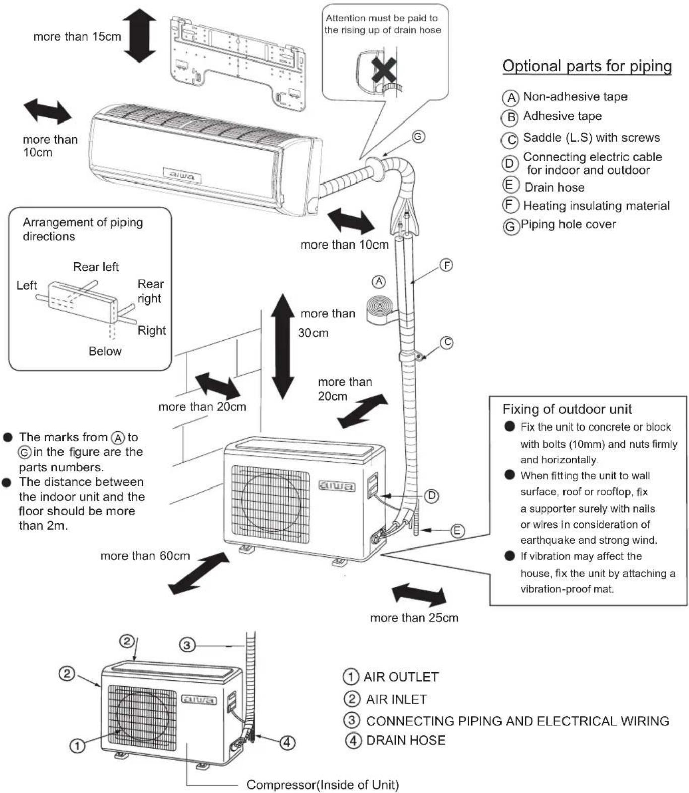

If using the left side drain pipe, make sure the hole is got through.
The above indoor and outdoor units' picture is just for your reference.
Please be subject to the actual product purchased.
Safety Precautions
Carefully read the following information in order to operate the air conditioner correctly.
Below are listed three kinds of Safety Precautions and Suggestions.
⚠ WARNING Incorrect operations may result in severe consequences of death or serious injuries.
⚠️ CAUTION Incorrect operations may result in injuries or machine damages; in some cases may cause serious consequences.
INSTRUCTIONS: These information can ensure the correct operation of the machine.
Symbols used in the illustrations
○: Indicates an action that must be avoided.
●: Indicates that important instructions must be followed.
♣ : Indicates a part which must be grounded.
④: Beware of electric shock (This symbol is displayed on the main unit label.)
After reading this handbook, hand it over to those who will be using the unit.
The user of the unit should keep this manual at hand and make it available to those who will be performing repairs or relocating the unit. Also, make it available to the new user when the user changes hands.
Be sure to conform with the following important Safety Precautions.
WARNING
- If any abnormal phenomena is found (e. g.smell of firing), please cut off the power supply immediately, and contact the dealer to find out the handling method.
Open the window and well ventilated the room. In such case, to continue using the conditioner will damage the conditioner, and may cause electrical shock or fire hazard.
• After a long time use of air-conditioner the base should be checked for any damages. If the damaged base is not repaired, the unit may fall down and cause accidents.
- Don't dismantle the outlet of the outdoor unit. The exposure of fan is very dangerous which may harm human beings.
- When need maintenance and repairment, call dealer to handle it.
Incorrect maintenance and repairment may cause water leak, electrical shock and fire hazard.
WARNING
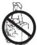
- No goods or nobody is permitted to placed on or stand on outdoor unit. The falling of goods and people may cause accidents.
- Don't operate the air-conditioner with damp hands. Otherwise it will be shocked.
- Only use explosion-proof fuse. May not use wire or any other materials replacing fuse, otherwise it may cause faults or fire accidents.
- Use discharge pipe correctly to ensure efficient discharge. Incorrect pipe use may cause water leaking.
- Air-conditioner can't be installed in the environment with inflammable gases because the inflammable gases near air-conditioner may cause fire hazard.
Please let the dealer be responsible for installing the conditioner. Incorrect installation may cause water leak, electrical shock and fire hazard.
- Call the dealer to take measures to prevent the refrigerant from leaking.
If conditioner is installed in a small room, be sure to take every measure in order to prevent suffocation accident even in case of refrigerant leakage.
- When conditioner is installed or reinstalled, the dealer should be responsible for them.
Incorrect installation may cause water leaking, electrical shock and fire hazard.
- Connect earthing wire.
Earthing wire should not be connected to the gas pipe, water pipe, lightning rod or phone line, incorrect earthing may cause shock.

Earthing
Safety Precautions
| ⚠ WARNING | |
| Have the unit professionally installed.Improper installation by an unqualified person may result in water leak, electric shock, or fire.Place the unit on a stable, level surface that withstands the weight of the unit to prevent the unit from tipping over or falling causing injury as a result.Only use specified cables for wiring. Securely connect each cable, and make sure that the cables are not straining the terminals.Cables not connected securely and properly may generate heat and cause fire.Take necessary safety measures against typhoons and earthquakes to prevent the unit from falling over.Do not make any changes or modifications to the unit. In case of problems, consult the dealer.If repairs are not made properly, the unit may leak water and present a risk of electric shock, or it may produce smoke or cause fire. | Be sure to carefully follow each step in this handbook when installing the unit.Improper installation may result in water leak, electric shock, fire or explosion.Have all electrical work performed by a licensed electrician according to the local regulations and the instructions given in this manual. Secure a circuit designated exclusively to the unit.Improper installation or a lack of circuit capacity may cause the unit to malfunction or present a risk of electric shock, fire or explosion.Securely attach the terminal cover(panel) on the unit.If installed improperly, dust and/or water may enter the unit and present a risk of electric shock, smoke or fire.Only use refrigerant R32 as indicated on the unit when installing or relocating the unit.The use of any other refrigerant or an introduction of air into the unit circuit may cause the unit to run an abnormal cycle and abnormal cycle and cause the unit to burst. |
| ⚠ WARNING | |
| Do not touch the fins on the heat exchanger with bare hands, for they are sharp and dangerous.In the event of a refrigerant gas leak, provide adequate ventilation to the room.If leaked refrigerant gas is exposed to a heat source, noxious gases, fire or explosion will be caused.Do not try to defeat the safety features of the devices, and do not change the settings.Defeating the safety features on the unit such as the pressure switch and temperature switch or using parts other than the dealer or specialist may result in fire or explosion. | When installing the unit in a small room, safeguard against hypoxia that results from leaked refrigerant reaching the threshold level.Consult the dealer for necessary measures to take.When relocating the air conditioner, consult the dealer or a specialist.Improper installation may result in water leak, electric shock, fire or explosion.After completing the service work, check for a refrigerant gas leak.If leaked gas refrigerant is exposed to a heat source such as fan heater, stove, and electric grill, noxious gases , fire or explosion.Only use specified parts.Have the unit professionally installed. Improper installation may cause water leak, electric shock, smoke ,fire,explosion. |
Precautions for Handling Units for Use with R32
| ⚠ Caution | |
| Do not use the existing refrigerant piping• The old refrigerant and refrigerator oil in the existing piping contain a large amount of chlorine, which will cause the refrigerator oil in the new unit to deteriorate.• 23R a2h8g1R-pressure refrigerant, and the use of the existing piping may result in bursting.Keep the inner and outer surfaces of the pipes clean and free of contaminants such as sulfur, oxides, dust/dirt shaving particles,oils,and moisture.• Contaminants inside the refrigerant piping will cause the refrigerant oil to deteriorate. | Use a vacuum pump with a reverse-flow check valve.• If other types of valves are used, the vacuum pump oil will flow back into the refrigerant cycle and cause the refrigerator oil to deteriorate.Do not use the following tools that have been used with the conventional refrigerants. Prepare tools that are for exclusive use with R32 . (Gauge manifold, charging hose, gas leak detector, reverse-flow check valve, refrigerant charge base,vacuum gauge, and refrigerant recovery equipment.)• If refrigerant and/or refrigerant oil left on these tools are mixed in with R32 , or if water is mixed with R32 , it will cause the refrigerant to deteriorate.• Since R32 does not contain chlorine, gas-leak detectors for conventional refrigerators will not work. |
| ⚠ Caution | |
| Store the piping to be used during installation indoors, and keep both ends of the piping sealed until immediately before brazing.(keep elbows and other joints wrapped in plastic.)If dust, dirt, or water enters the refrigerant cycle, it may cause the oil in the unit to deteriorate or may cause the compressor to malfunction.Use a small amount of ester oil, ether oil, or alkylbenzene to coat flares and flange connections.A large amount of mineral oil will cause the refrigerating machine oil to deteriorate.Use liquid refrigerant to charge the system.Charge the unit with gas refrigerant will cause the refrigerant in the cylinder to change its composition and will lead to a drop in performance | Do not use a charging cylinder.The use of charging cylinder will change the composition of the refrigerant and lead to power loss.Exercise special care when handling the tools.An introduction of foreign objects such as dust, dirt or water into the refrigerant cycle will cause the refrigerating machine oil to deteriorate.Only use R32 refrigerant.The use of refrigerants containing chlorine(i.e. R22) will cause the refrigerant to deteriorate. |
Before Installing the Unit
| ⚠ Caution | |
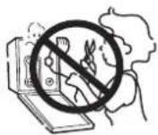
| Do not install the unit in a place where there is a possibility of flammable gas leak.Leaked gas accumulated around the unit may start a fire.Do not use the unit to preserve food, animals, plants, artifacts, or for other special purposes.The unit is not designed to provide adequate conditions to preserve the quality of these items.Do not use the unit in an unusual environmentThe use of the unit in the presence of a large amount of oil, steam, acid, alkaline solvents or special types of sprays may lead to a remarkable drop in performance and/or malfunction and presents a risk of electric shock, smoke, or fire.The presence of organic solvents, corroded gas (such as ammonia,sulfur compounds,and acid may cause gas or water leak.) | When installing the unit in a hospital, take necessary measures against noise.High-frequency medical equipment may interfere with the normal operation of the air conditioning unit or the air conditioning unit may interfere with the normal operation of the medical equipmentDo not place the unit on or over things that may not get wet.When humidity level exceeds 80% or when the drainage system is clogged, indoor units may drip water.Installation of a centralized drainage system for the outdoor unit may also need to be considered to prevent water drips from the outdoor units. |
Before Installing (Relocating) the Unit or Performing Electric Work
| ⚠ Caution | |
| Ground the unit.Do not connect the grounding on the unit to gas pipes,water pipes, lightning rods, or the grounding terminals of telephones. Improper grounding presents a risk of electric shock, smoke, fire, or the noise caused by improper grounding may cause the unit to malfunction.Make sure the wires are not subject to tension.If the wires are too taut, they may break or generate heat and/or smoke and cause fire.Install a explosion-proof breaker for current leakage at the power source to avoid the risk of the electric shock.Without a breaker for current leakage will cause risks of electric shock, fire or explosion.Do not use large-capacity fuses,steel wire,or copper wire. Damaging the unit ,fire,smoke or explosion will be caused otherwise. | Do not spray water on the air conditioners or immerse the air conditioners in water.Water on the unit presents a risk of electric shock.Periodically check the platform on which is placed for damage to prevent the unit from falling.If the unit is left on a damaged plarform, it may topple over, causing injury.When installing draining pipes, follow the instructions in the manual, and make sure that they properly drain water so as to avoid dew condensation.If not installed properly, they may cause water leaks and damage the furnishings.Properly dispose of the packing materials.Things such as nails may be included in the package.Dispose of them properly to prevent injury.Plastic bags present a choking hazard to children. Tear up the plastic bags before disposing of them to prevent accidents. |
Before the Test Run
| ⚠ Caution | |
| Do not operate switches with wet hands to avoid electric.Do not touch the refrigerant pipes with bare hands during and immediately after operation.·Depending on the state of the refrigerant in the system, certain parts of the unit such as the pipes and compressor may become very cold or hot and may subject the person to frost bites or burning.Do not operated the unit without panels and safety guards in their proper places.·They are there to keep the users from injury from accidentally touching rotating, high-temperature or high-voltage parts. | Do not turn off the power immediately after stopping the unit.·Allow for at least five minutes before turning off the unit, otherwise the unit may leak water or experience other problems.Do not operate the unit without air filters.·Dust particles in the air may clog the system and cause malfunction. |
Read Before Installation
Items to Be Checked
(1). Verify the type of refrigerant used by the unit to be serviced. Refrigerant Type: R32
(2). Check the symptom exhibited by the unit to be serviced. Look in this service handbook for symptoms relating to the refrigerant cycle.
(3). Be sure to carefully read the safety precautions at the beginning of this document.
(4). If there is a gas leak or if the remaining refrigerant is exposed to an open flame, a noxious gas hydrofluoric acid may form. Keep workplace well ventilated.
CAUTION
• Install new pipes immediately after removing old ones to keep moisture out of the refrigerant circuit.
- Chloride in some types of refrigerants such as R22 will cause the refrigerating machine oil to deteriorate.
Necessary Tools and Materials
Prepare the following tools and materials necessary for installing and servicing the unit.
Necessary tools for use with R32 (Adaptability of tools that are for use with R22 and R407C).
- To be used exclusively with R32 (Not to be used if used with R22 or R407C)
| Tools/Materials | Use | Notes |
| Gauge Manifold | Evacuating,refrigerant charging | 5.09MPa on the High-pressure side. |
| Charging Hose | Evacuating, refrigerant charging | Hose diameter larger than the conventional ones. |
| Refrigerant Recovery Equipment | Refrigerant recovery | |
| Refrigerant Cylinder | Refrigerant charging | Write down the refrigerant type. Pink in color at the top of the cylinder. |
| Refrigerant Cylinder Charging Port | Refrigerant charging | Hose diameter larger than the conventional ones. |
| Flare Nut | Connecting the unit to piping | Use Type-2 Flare nuts. |
- Tools and materials that may be used with R32 with some restrictions
| Tools/Materials | Use | Notes |
| Gas leak detector | Detection of gas leaks | The ones for HFC type refrigerant may be used. |
| Vacuum Pump | Vacuum drying | May be used if a reverse flow check adaptor is attached. |
| Flare Tool | Flare machining of piping | Chages have been made in the flare machining dimension.Refer to the next page. |
| Refrigerant Recovery Equipment | Recovery of refrigerant | May be used if designed for use with R32 . |
- Tools and materials that are used with R22 or R407C that can also be used with R32
| Tools/Materials | Use | Notes |
| Vacuum Pump with a Check Valve | Vacuum drying | |
| Bender | Bending pipes | |
| Torque Wrench | Tightening flare nuts | Only 12.70 (1/2") and 15.88(5/8") have a larger flare machining dimension. |
| Pipe Cutter | Cutting pipes | |
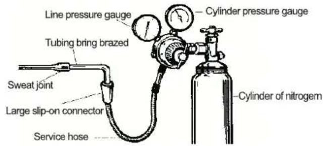
| Welder and Nitrogen Cylinder | Welding pipes | |
| Refrigerant Charging Meter | Refrigerant charging | |
| Vacuum Gauze | Checking vacuum degree |
- Tool and materials that must not used with R32
| Tools/Materials | Use | Notes |
| Charging Cylinder | Refrigerant Charging | Must not be used with R32 -type units. |
Tools for R32 must be handled with special care, and keep moisture and dust from entering the cycle.
Piping Materials
Types of Copper Pipes (Reference)
| Maximum Operation Pressure | Applicable Refrigerants |
| 3.4MPa | R22, R407C |
| 4.3 MPa | R32 |
- Use pipes that meet the local standards.
Piping Materials/Radial Thickness
Use pipes made of phosphorus deoxidized copper.
Since the operation pressure of the units that use R32 is higher than that of the units for use with R22, use pipes with at least the radial thickness specified in the chart below. (Pipes with a radial thickness of 0.7mm or less may not be used.)
| Size(mm) | Size(inch) | Radial Thickness(mm) | Type |
| 6.35 | 1/4" | 0.8t | Type-O pipes |
| 9.52 | 3/8" | 0.8t | |
| 12.7 | 1/2" | 0.8t | |
| 15.88 | 5/8" | 1.0t | |
| 19.05 | 3/4" | 1.0t | Type-1/2H or Hpipes |
- Although it was possible to use type-O for pipes with a size of up to 19.05(3/4") with conventional refrigerants, use type-1/2H pipes for units that use R32 . (Type-O pipes may be used if the pipe size is 19.05 and the radial thickness is 1.2t.)
• The table shows the standards in Japan. Using this table as a reference, choose pipes that meet the local standards.
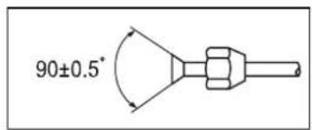
Flare Machining (type-O and OL only)
The flare machining dimensions for units that use R32 is larger than those for units that use R22 in order to increase air tightness.
Flare Machining Dimension(mm)
| External dimension of pipes | Size | Dimension A | |
| R32 | R22 | ||
| Φ6.35 | 1/4" | 9.1 | 9.0 |
| Φ9.52 | 3/8" | 13.2 | 13.0 |
| Φ12.7 | 1/2" | 16.6 | 16.2 |
| Φ15.88 | 5/8" | 19.7 | 19.4 |
| Φ19.05 | 3/4" | 24.0 | 23.3 |
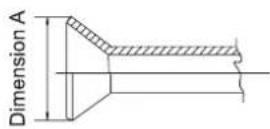
If a clutch type flare tool is used to machine flares on units that use R32, make the protruding part of the pipe between 1.0 and 1.5mm. Copper pipe gauge for adjusting the length of pipe protrusion is useful.
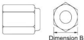
Flare Nut
Type-2 flare nuts instead of type-1 nuts are used to increase the strength. The size of some of the flare nuts have also been changed.
Flare nut dimension(mm)
| External dimension of pipes | Size | Dimension B | |
| R32 (Type2) | R22(Type1) | ||
| Φ6.35 | 1/4" | 17.0 | 17.0 |
| Φ9.52 | 3/8" | 22.0 | 22.0 |
| Φ12.7 | 1/2" | 26.0 | 24.0 |
| Φ15.88 | 5/8" | 29.0 | 27.0 |
| Φ19.05 | 3/4" | 36.0 | 36.0 |
natural_image
Technical drawing of a hexagonal nut with dimension label (Dimension B) shown in front and side views (no text or symbols beyond label)- The table shows the standards in Japan. Using this table as a reference, choose pipes that meet the local standards.
Air Tightness Test
No changes from the conventional method. Note that a refrigerant leakage detector for R22 or R410A cannot detect R32 leakage.

Halide torch
R22 or R407C leakage detector
Items to be strictly observed :
- Pressurize the equipment with nitrogen up to the design pressure and then judge the equipment's air tightness, taking temperature variations into account.
- When investigating leakage locations using a refrigerant, be sure to use R32.
- Ensure that R32 is in a liquid state when charging.
Reasons:
- Use of oxygen as the pressurized gas may cause an explosion.
- Charging with R32 gas will lead the composition of the remaining refrigerant in the cylinder to change and then this refrigerant can not be used.
Vacuuming
1. Vacuum pump with check valve
A vacuum pump with a check valve is required to prevent the vacuum pump oil from flowing back into the refrigerant circuit when the vacuum pump power is turned off (power failure). It is also possible to attach a check valve to the actual vacuum pump afterwards.
2. Standard degree of vacuum for the vacuum pump
Use a pump which reaches 65Pa or below after 5 minutes of operation.
In addition, be sure to use a vacuum pump that has been properly maintained and oiled using the specified oil. If the vacuum pump is not properly maintained, the degree of vacuum may be too low.
3. Required accuracy of the vacuum gauge
Use a vacuum gauge that can measure up to 650Pa. Do not use a general gauge manifold since it cannot measure a vacuum of 650Pa.
4.Evacuating time
Evacuate the equipment for 1 hour after 650Pa has been reached.
After envacuating, leave the equipment for 1 hour and make sure the that vacuum is not lost.
5. Operating procedure when the vacuum pump is stopped
In order to prevent a backflow of the vacuum pump oil, open the relief valve on the vacuum pump side or loosen the charge hose to drawn in air before stopping operation. The same operating procedure should be used when using a vacuum pump with a check valve.
Charging Refrigerant
R32 must be in a liquid state when charging.
Reasons:
R32 is a HFC refrigerant (boiling point = -52°C) and can roughly be handled in the same way as R410A; however, be sure to fill the refrigerant from the liquid side, for doing so from the gas side will somewhat change the composition of the refrigerant in the cylinder.
Note
- In the case of a cylinder with a syphon, liquid R32 is charged without turning the cylinder up side down. Check the type of cylinder before charging.
Remedies to be taken in case of a refrigerant leak
When refrigerant leaks, additional refrigerant may be charged. (Add the refrigerant from the liquid side)
Characteristics of the Conventional and the New Refrigerants
- Because R32 is a simulated azeotropic refrigerant, it can be handled in almost the same mammer as a single refrigerant such as R22. However, if the refrigerant is removed in the vapor phase, the composition of the refrigerant in the cylinder will somewhat change.
- Remove the refrigerant in the liquid phase. Additional refrigerant may be added in case of a refrigerant leak.
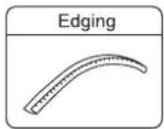
1. Accessories
"Edging" for protection of electrical wires from an opening edge.
2. Selection of the place of installation
Select the place of installation satisfying the following conditions and, at the same time, obtain a consent from the client or user.
- Place where air circulates.
- Place free from heat radiation from other heat sources.
- Place where drain water may be discharged.
- Place where noise and hot air may not disturb the neighborhood.
- Place where there is not heavy snowfall in the winter time.
- Place where obstacles do not exist near the air inlet and air outlet.
- Place where the air outlet may not be exposed to a strong wind.
- Avoid mounting guide-louvers to the place where short-circuit is a possibility.
- Place surrounded at four sides are not suitable for installation. A 1m or more of overhead space is needed for the unit.
- When installing several units, secure sufficient suction space to avoid short circuiting.
Open space requirement around the unit
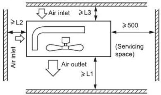
| Distance | |||
| L1 | open | open | 500 mm |
| L2 | 300 mm | 300 mm | open |
| L3 | 150 mm | 300 mm | 150 mm |
Note :
(1) Fix the parts with screws.
(2) Don't intake the strong wind directly to the outlet air-flow hole.
(3) A one meter distance should be kept from the unit top.
(4) Don't block the surroundings of the unit with sundries.
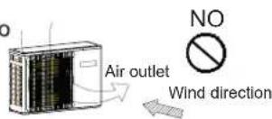
(5) If the outdoor unit is installed in a place that is exposed to the wind, install the unit so that the outlet grid is NOT pointing in the direction of the wind.
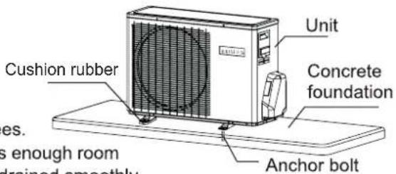
3. Installation of outdoor unit
Fix the unit on the foundation in a proper way according to the condition of the installation place, referring to the following information.
- Give enough room for the concrete foundation to fix by anchor bolts.
- Place the concrete foundation deep enough.
• Install the unit so that the angle of inclination must be less than 3 degrees. - Forbidden to place the unit on the ground directly. Please confirm there is enough room near the drainage hole on bottom plate, which will ensure the water be drained smoothly.
4. Installation dimension(Unit:mm)
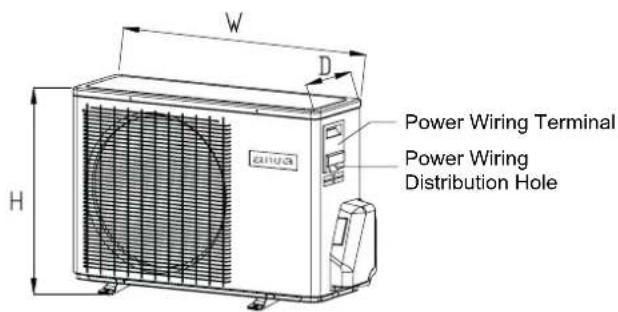
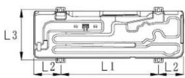
The values of The installation dimension are shown in table 3
1. Piping size
• Install the removed flare nuts to the pipes to be connected, then flare the pipes.
• The values of The piping size are shown in table 4
2. Connection of pipes
● To bend a pipe, give the roundness as large as possible not to crush the pipe, and the bending radius should be 30 to 40 mm or longer.
● Connecting the pipe of gas side first makes working easier.
● The connection pipe is specialized for R32.
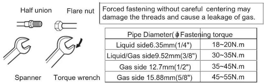
Be careful that matters, such as wastes of, veated, etc. shall not enter the pipe.
CAUTION
The standard pipe length is C m. If it is over D m, the function of the unit will be affected. If the pipe has to be lengthened, the refrigerant should be charged, according to E g/m. But the charge of refrigerant must be conducted by professional air conditioner engineer. Before adding additional refrigerant, perform air purging from the refrigerant pipes and indoor unit using a vacuum pump, then charge additional refrigerant.
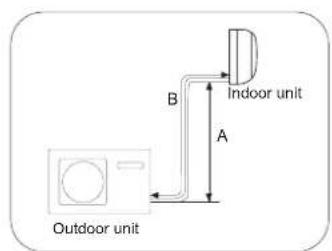
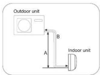
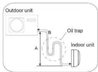
• Max.Elevation: Amax
- In case the elevation A is more than 5m, oil trap should be installed every 5\~7
Max. Length: Bmax
• Mi n. Length: B min
- In case the pipe length B is more than Dm, the refrigerant should be charged, according to E g/m.
The values are shown in table 5
After finishing connection of refrigerant pipe, it shall perform air tightness test.
- The air tightness test adopts nitrogen tank to give pressure according to the pipe connection mode as the following figure shown.
- The gas and liquid valve are all in close state. In order to prevent the nitrogen entering the circulation system of outdoor unit, tighten the valve rod before giving pressure (both gas and liquid valve rods).
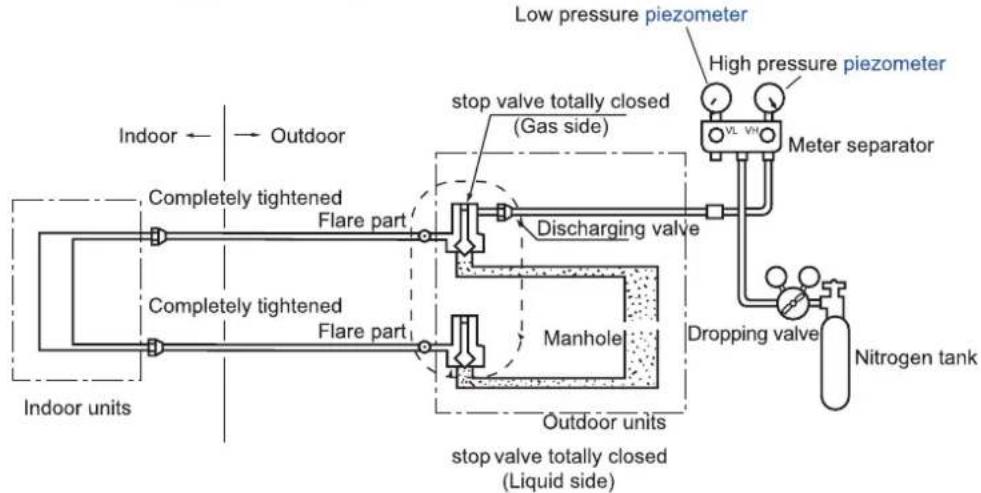
flowchart
graph TD
    A["Indoor"] --> B["Completely tightened Flare part"]
    B --> C["Stop valve totally closed (Gas side)"]
    C --> D["Manhole"]
    D --> E["Outdoor units stop valve totally closed (Liquid side)"]
    E --> F["Outdoor units Indoor units"]
    G["Low pressure piezometer"] --> H["High pressure piezometer"]
    I["Meter separator"] --> J["DL/VH"]
    K["Dropping valve"] --> L["Nitrogen tank"]
    M["Discharging valve"] --> N["Flare part"]
    O["stop valve totally closed"] --> P["Flare part"]
    Q["stop valve totally closed"] --> R["Manhole"]
1) Pressurize for over 3 minutes at 0.3MPa (3.0 kg/cm ^2 g).
2) Pressurize for over 3 minutes at 1.5MPa (15 kg/cm ^2 g). A large leakage will be found.
3) Pressurize for about 24 hours at 3.0MPa (30 kg/cm ^2 g). A small leakage will be found.
- Check if the pressure drops
If the pressure does not drop, then pass.
If the pressure drops, then please check the leaking point.
When pressurizing for 24 hours, a variation of 1^ in the ambient temperature will cause a variation of 0.01MPa(0.1kg / cm^2g) in pressure. It shall be corrected during test.
- Checking the leaking point
In 1) to 3) steps, if the pressure drops, check the leakage in each joint by listening, touching and using soap water etc. to identify the leaking point. After confirming the leaking point, welding it again or tighten the nut tightly again.
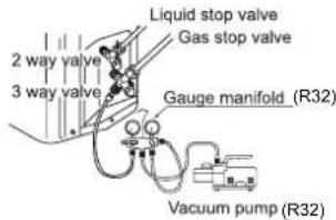
Piping vacuum method: to use vacuum pump
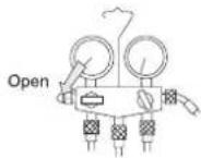
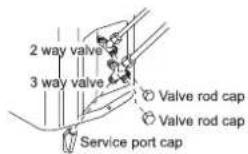
- Detach the service port's cap of 3-way valve, the valve rod's cap for 2-way valve and 3-way valves, and connect the service port into the projection of charge hose (low) for gaugemanifold. Then connect the projection of charge hose (center) for gaugemanifold into vacuum pump.
- Open the handle at low in gaugemanifold, and operate vacuum pump. If the scale-moves of gause (low) reach vacuum condition in a moment, check the step 1 again.
- Vacuumize for over 15min. And check the level gauge which should read -0.1MPa (-76 cm Hg) at low pressure side. After the completion of vacuumizing, close the handle 'Lo' in the vacuum pump. Check the condition of the scale and hold it for 1-2min. If the scale-moves back in spite of tightening, make flaring work again, then return to the beginning of the step 3.
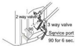
- Open the valve rod for the 2-way valve to an angle of anticlockwise 90 degree. After 6 seconds, close the 2-way valve and make the inspection of gas leakage.
2 way valve

3 way valve


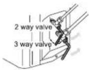
- No gas leakage? In case of gas leakage, tighten parts of pipe connection. If leakage stops, then proceed the step 6. If it does not stop gas leakage, discharge whole refrigerants from the service port. After flaring work again and vacuumize, fill up prescribed refrigerant from the gas cylinder.
- Detach the charge hose from the service port, open 2-way valve and 3-way. Turn the valve rod anticlockwise until hitting lightly.
- To prevent the gas leakage, turn the service ports cap, the valve rodis cap for 2-way valve and 3-way's a little more than the point where the torque increases suddenly.
CAUTION:
If the refrigerant of the air conditioner leaks, it is necessary to make all the refrigerant out. Vacuumize first, then charge the liquid refrigerant into air conditioner according to the amount marked on the nameplate.
WARNING!
DANGER OF BODILY INJURY OR DEATH
- TURN OFF ELECTRIC POWER AT CIRCUIT BREAKER OR POWER SOURCE BEFORE MAKING ANY ELECTRIC CONNECTIONS.
• GROUND CONNECTIONS MUST BE COMPLETED BEFORE MAKING LINE VOLTAGE CONNECTIONS.
Precautions for Electrical wiring
- Electrical wiring work should be conducted only by authorized personnel.
- Do not connect more than three wires to the terminal block. Always use round type crimped terminal lugs with insulated grip on the ends of the wires.
- Use copper conductor only.
Selection of size of power supply and interconnecting wires
Select wire sizes and circuit protection from table6. (This table shows 20 m length wires with less than 2% voltage drop.)
- If the supply cord is damaged, it must be replaced by the manufacturer or its service agent or a similar qualified person.
- If the fuse of control box is broken, please change it with the ceramic type of T 25A/250V.
- The wiring method should be in line with the local wiring standard.
- All the cables shall have got the European authentication certificate. During installation, when the connecting cables break off, it must be assured that the grounding wire is the last one to be broken off.
- The explosion-proof breaker of the air conditioner should be all-pole switch. The distance between its two contacts should not be no less than 3mm. Such means for disconnection must be incorporation in the fixed wiring.
- The distance between its two terminal blocks of indoor unit and outdoor unit should not be over 5m. If exceeded, the diameter of the wire should be enlarged according to the local wiring standard.
- A explosion-proof breaker must be installed.
Wiring procedure
1) Remove set screws on the side before taking off the front panel toward the direction.
2) Connect wires to the terminal block correctly and fix the wires with a wire clamp equipped nearby the terminal block.
3) Route the wires in a proper way and penetrate the wires through the opening for electrical wiring on the side panel.
WARNING:
INTERCONNECTING WIRES MUST BE WIRED ACCORDING TO FIGURE 1. INCORRECT WIRING MAY CAUSE EQUIPMENT DAMAGE.
CAUTION!
- THIS UNIT WILL BE STARTED INSTANTLY WITHOUT "ON" OPERATION WHEN ELECTRIC POWER IS SUPPLIED. BE SURE TO EXECUTE "OFF" OPERATION BEFORE ELECTRIC POWER IS DISCONNECTED FOR SERVICING.
- This unit has a function of automatic restart system after recovering power stoppage.
1. Before starting test run (for all Heat pump models)
Confirm whether the power source breaker (main switch) of the unit has been turned on for over 12 hrs to energize the crankcase heater in advance of operation.
2. Test run
Run the unit continuously for about 30 minutes, and check the following.
- Suction pressure at check joint of service valve for gas pipe.
- Discharge pressure at check joint on the compressor discharge pipe.
- Temperature difference between return air and supply air for indoor unit.
| Flash times of LED on mainboard | Trouble description | Analyze and diagnose |
| 1 | Eeprom failure | Outdoor main board eeprom fail |
| 2 | IPM failure | IPM failure |
| 4 | Communication error between main board and spdu module SPDU Communication error | Communication fail over 4min |
| 5 | High pressure protection | System high pressure over 4.3 Mpa |
| 8 | Compressor discharging temperature protection | Compressor discharging temperature over 110 centigrade |
| 9 | Abnormal of DC motor | Jam of DC motor or motor failure |
| 10 | Abnormal of piping sensor | Piping sensor short-circuit or open-circuit |
| 11 | Suction temperature sensor failure | When the The wiring of compressor is wrong or the connection is poor |
| 12 | Abnormal of outdoor ambient sensor | Outdoor ambient sensor short-circuit or open-circuit |
| 13 | Abnormal of compressor discharge sensor | Compressor discharge sensor short-circuit or open-circuit |
| 15 | Communication error between indoor and outdoor unit | Communication fail over 4min |
| 16 | Lack of refrigerant | Check if there is leakage in the unit. |
| 17 | 4-way valve reverse failure | Alarm and stop if detect Tm<=0 last for 1min after compressor has started for 10min in heating mode, confirm the failure if it appears 3 times in one hour. |
| 18 | Compressor jam(only for spdu) | Inner compressor is abnormal jamed |
| 19 | Module PWM select circuit error | Module PWM select wrong circuit |
| 25 | Compressor U-phase over-current | The current of compressor U-phase is too high |
| 25 | Compressor V-phase over-current | The current of compressor V-phase is too high |
| 25 | Compressor W-phase over-current | The current of compressor W-phase is too high |
AIRE ACONDICIONADO
natural_image
Line drawing of a Siemens air conditioner unit with fan grille and control panel (no text or symbols on body)Serie AIWA HaruAir
Serie AIWA FūjinAir
Serie AIWA KazéAir
Contenido
ADVERTENCIA ....1
natural_image
Illustration of wrench tool tips showing different types of tools (no text or symbols present)natural_image
Line drawing of a Siemens air conditioner unit with fan grille and control panel (no text or symbols on body)Serie AIWA HaruAir Serie AIWA FujinAir Serie AIWA KazéAir
Indice
Avvertenze----1
natural_image
Illustration of a person kneeling at a desk with a device and directional arrow (no text or symbols)1) Fissaggio
1) USCITA DELL'ARIA
2) INGRESSO ARIA
3) CONNESSIONE DELLE TUBAZIONI E DEI CAVI ELETTRICI
4) TUBO DI SCARICO FLESSIBILE
natural_image
Illustration of three different wrench tool tips ( threaded, hexagonal, and curved) showing different mechanical configurations (no text or symbols)CLIMATISEUR CHAMBRE INSTALLATION MANUEL

natural_image
Line drawing of a Siemens air conditioner unit with fan grille and control panel (no text or symbols on body)Table des matières
ALERTE....1
Exigences de manutention/ gestion du transport/ stockage.... 3
natural_image
Illustration of a person kneeling at a desk near a security camera, with no visible text or symbolsnatural_image
Line drawing of a Siemens air conditioner unit with fan grille and control panel (no text or symbols on body)AIWA HaruAir-Serie
AIWA FūjinAir-Serie
AIWA KazéAir-Serie
Inhaltverzeichnis
Warnung....1
GWP = Global Warming Potential (Treibhauspotential)
natural_image
Line drawing of a Siemens air conditioner unit with fan grille and control panel (no text or symbols on the device itself)Série AIWA HaruAir
Série AIWA FujiAir
Série AIWA KazéAir
índice
ADVERTÊNCIA ....1
natural_image
Silhouette of a person kneeling at a desk with a red circular arrow and a small object, no text or symbols present.① SAÍDA DE AR
② ENTRADA DE AR
③ LIGAÇÃO TUBOS E CABOS ELÉTRICOS
④ MANGUEIRA DE DRENAGEM
natural_image
Line drawing of a Siemens air conditioner unit with fan grille and control panel (no text or symbols on body)Seria AIWA HaruAir
Seria AIWA FūjinAir
Seria AIWA KazéAir
Spis treści
Ostrzeżenie 1
natural_image
Illustration of a person kneeling at a security camera with a red circular arrow indicating proximity (no text or symbols)1) Mocowanie
natural_image
Line drawing of a Siemens air conditioner unit with fan grille and control panel (no text or symbols on body)AIWA HaruAir Serisi
AIWA FūjinAir Serisi
AIWA KazéAir Serisi
iÇİNDEKİLER
UYARI 1
natural_image
Illustration of a person kneeling at a security camera with a red circular arrow indicating proximity (no text or symbols)1) Montaj ve sabitleme
| Boruların harici ölçüsü | Boyut | Ölçü B | |
| R32(Tip2) | R22 (Tip 1) | ||
| 6,35 | 1/4" | 17,0 | 17,0 |
| 9,52 | 3/8" | 22,0 | 22,0 |
| 12,7 | 1/2" | 26,0 | 24,0 |
| 15,88 | 5/8" | 29,0 | 27,0 |
| $19,05 | 3/4" | 36,0 | 36,0 |
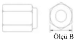
natural_image
Line drawing of a Siemens air conditioner unit with fan grille and control panel (no text or symbols on body)Σειρά AIWA HaruAir
Σειρά AIWA FūjinAir
Σειρά AIWA KazéAir
Κατάλογος
Climate:T1Voltage:230V
CE
natural_image
Line drawing of a Siemens air conditioner unit with fan grille and control panel (no text or symbols on body)Serija AIWA HaruAir
Serija AIWA FūjinAir
Serija AIWA KazéAir
- Prije instalacije pažljivo pročitajte ovaj priručnik.
SADRŽAJ
Upozorenje....1
ZAHTEVI ZA UTOVAROM I STOVAROM/UPRAVLJANJEM TRANSPORTOVANJEM/SKLADIŠTENJEM ....3
UPUTSTVO ZA MONTIRANJE....3
Procedure Pomeranja 7
Uputstvo za odrčavanje i popravak 7
ISPADANJE IZ UPOTREBE I POVRATAK NATRAG ....10
MINIMALNA POVRŠINA SOBE
| Tip | LFL kg/m^3 | Ukupna masa punjenja/ kg Minimalna površina sobe/ m^2 | |||||
| R32 | 0.307 | 1.781 | 2.519 | 3.708 | 4.932 | 6.170 | 7.965 |
| 3 | 6 | 13 | 23 | 36 | 60 | ||
Vrijednosti Maksimalne količine punjenja rashladnog sredstva prikazane su u tablici 2
2. Raspored cjevovoda
Kad se rasporede spojne cijevi, crijevo za drenažu, kabel napajani na uređaj, crijevo za drenažu treba biti niže od kabela napajanog na uređaj, kabel napajanja i kabel napajani na uređaj trebaju biti odvojeni, crijevo za drenažu obavezno je biti zaštićeno toploizolacionim materijalima.
3. Punjenje dušika za održavanje pritiska i detekcija curenja
Nakon što je isparivač unutarnje jedinice spojen na priključak cijevi (nakon zavarivanja), posle podešavanja pritiska u boci dušika i punjenja dušika preko 4,0MPa od boce dušika u unutru isparivača i cijevi spojene na isparivač, zatvori ventil na boci dušika. Nakon toga, izvrši inspekciju curenja vodom sa sapunom ili drugim tečnostima za inspekciju curenja. Pritisak će se održavati za više od 5 minuta, a zatim progleda da li tlak u sustavu se smanjuje. U slučaju da je tlak smanjen, curenje se može identificirati. Nakon što je tačkom curenja rukuje, koraci punjenja naprijed treba ponoviti.
Nakon spajanja isparivača na unutarnjoj jedinici i spojenog cijevododa, održavanja pritiska na stabilnom nivou, spajanja dvosmernog zapornog ventila i T-zapornog ventila i zatezanja bakrene kapice na spojenom cijevovodu, puni se dušikom sa više od 4,0 M P a u tehnološki otvor (otvor za popravke) T-zapornog ventila na vanjskoj jedinici, zatvori ventil na boci dušika. Nakon toga, izvrši inspekciju curenja vodom sa sapunom ili drugim tečnostima za inspekciju curenja. Pritisak će se održavati za više od 5 minuta, a zatim pregleda da li tlak u sustavu se smanjuje. U slučaju da se smanjuje tlak, curenje se može identificirati. Nakon što je tačkom curenja rukuje, koraci punjenja naprijed treba ponoviti.
Gore pomenute operacije mogu biti dovršene nakon povezivanja unutarnje jedinice s priključnim cjevovodima, posle spajanja dvosmjernog zapornog ventila i T-zapornog ventila vanjske jedinice, spoji otvor za popravke vanjske jedinice s bocom dušika sa tlakomerom, puni dušik više od 4,0MPa tlaka i zadržava tlak 5 minuta i izvrši inspekciju curenja kod priključka ili tačke zavarivanja unutarnje jedinice i priključka dvosmernog zapornog ventila i T-zapornog ventila na vanjskoj jedinici, i za vreme montiranja mora biti zajamčeno da je svaki priključak u stanju u kojem se može izvršiti inspekciju curenja.
Nakon završetka gore navedenih procedura (punjenje dušika, zadržavanje tlaka i inspekcija curenja), može izvršiti sledeće korake: pražnjenje pomoću podtlačne pumpe.
• Montiranje vanjske jedinice
| Vanjska dimenzija cijevi | Veličina | Dimenzija B | |
| R32 (tip2) | |||
| 6,35 | 1/4" | 17,0 | 6,35 |
| 9,52 | 3/8" | 22,0 | 9,52 |
| 12,7 | 1/2" | 26,0 | 12,7 |
| 15,88 | 5/8" | 29,0 | 15,88 |
| 19,05 | 3/4" | 36,0 | 19,05 |
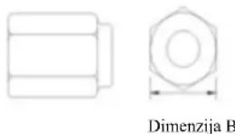
- Tablica prikazuje japanske standarde. Koristeći ovu tablicu kao referencu, izaberite cijevi koje zadovoljavaju lokalne standarde.
Ispitivanje nepropusnosti
Nema promjene u odnosu na konvencionalne metode. Imajte na umu da detektor curenja za R22 ili R407 ne može detektirati curenje R32.
Halidna svjetiljka
Detektor ispuštanja R22 ili R407C
Stavke koje se moraju strogo poštovati:
natural_image
Line drawing of a Siemens air conditioner unit with fan grille and control panel (no text or symbols on the device itself)Серия AIWA HaruAir
Серия AIWA FūjinAir
Серия AIWA KazéAir
КУ ДЕРЖАНИЕ
natural_image
Illustration of a person kneeling at night near a trash bin with red circular motion arrows indicating direction (no text or symbols)1. Монтаж
natural_image
Line drawing of a Siemens air conditioner unit with fan grille and control panel (no text or symbols on body)AIWA HaruAir-serie
AIWA FūjinAir-serie
AIWA KazéAir-serie
Inhoudsopgave
Contents
WAARSCHUWING:....1
LADEN EN LOSSEN/TRANSPORT MANAGEMENT/OPSLAGCONDITIONS 1
INSTALLATIE INSTRUCTIES....1
VERPLAATSING PROCEDURES....3
VERSCHROTTEN EN RECUPERATIE 6
BINNEN/BUITEN UNIT INSTALLATIETEKENINGEN....8
VEILIGHEIDSVOORSCHRIFTEN....1
LEES VÓÓR INSTALLATIE 5
MONTAGE PROCEDURE 8
BUITENUNIT PROBLEEMOPLOSSING 13

natural_image
Illustration of a person kneeling at a desk near a wall-mounted device, with no visible text or symbols.1) Bevestiging
natural_image
Simple line drawing of a mechanical device with a circular base and curved arm (no text or symbols)
natural_image
Simple line drawing of a rectangular block with a small square top and curved lines, no text or symbols present.Halide torch R22 or R407C leakage detector