DNX1500S - Hand blender Denon DJ - Free user manual and instructions
Find the device manual for free DNX1500S Denon DJ in PDF.
| Product Type | Professional DJ Mixer |
| Brand | Denon DJ |
| Model | DNX1500S |
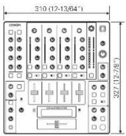
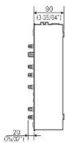
| Dimensions (W x H x D) | 310 x 30 x 327 mm |
| Weight | 5.8 kg |
| Power Supply | 120 V AC 60 Hz or 230 V AC 50 Hz, 45 W |
| Inputs | 3 phono (RCA), 5 line (RCA), 2 mic (XLR/Jack), 2 return (Jack TS) |
| Outputs | Master balanced (XLR), Master unbalanced (RCA), Booth (RCA), Rec (RCA), digital coaxial, headphone (6.35 mm Jack) |
| Equalizer | 3-band per channel (HI, MID, LOW) with adjustable gain |
| Built-in Effects | Delay, Echo, Pan, Trans, Filter, Flanger, Key |
| Sampler | Digital, up to 8 seconds, with Loop, Reverse, Stutter modes |
| BPM Functions | Auto BPM, Tap BPM, Manual, Lock |
| Fader Start | Yes, with compatible Denon players |
| FLEX FADER | Crossfader with tension adjustment |
| Maintenance | Clean with a soft, dry cloth. Do not use harsh chemicals. |
| Safety | Do not expose to water or flames. Ensure adequate ventilation. Disconnect before cleaning. |
| Spare Parts | Contact an authorized Denon DJ service center. |
| Repairability | Repairability index not disclosed. Consult a professional. |
Frequently Asked Questions - DNX1500S Denon DJ
User questions about DNX1500S Denon DJ
0 question about this device. Answer the ones you know or ask your own.
Ask a new question about this device
Download the instructions for your Hand blender in PDF format for free! Find your manual DNX1500S - Denon DJ and take your electronic device back in hand. On this page are published all the documents necessary for the use of your device. DNX1500S by Denon DJ.
USER MANUAL DNX1500S Denon DJ
The lightning flash with arrowhead symbol, within an equilateral triangle, is intended to alert the user to the presence of uninsulated "dangerous voltage" within the product's enclosure that may be of sufficient magnitude to constitute a risk of electric shock to persons.

The exclamation point within an equilateral triangle is intended to alert the user to the presence of important operating and maintenance (servicing) instructions in the literature accompanying the appliance.
WARNING: TO PREVENT FIRE OR SHOCK HAZARD, DO NOT EXPOSE THIS APPLIANCE TO RAIN OR MOISTURE.
CAUTION:
1. Handle the power supply cord carefully
Do not damage or deform the power supply card. If it is damaged or deformed, it may cause electric shock or malfunction when used. When removing from wall outlet, be sure to remove by holding the plug attachment and not by pulling the core.
2. Do not open the top cover
In order to prevent electric shock, do not open the top cover.
If problems occur, contact with PENON phone
3. Do not place anything inside
Do not place metal objects or spill liquid inside the DJ mixer.
Electric shock or malfunction may result.
Please, record and retain the Modal name and serial number of your set shown on the rating label.
Model No.DN-X1500S Serial No.
FCC INFORMATION (For US customers)
1.PRODUCT
This product complies with Part 15 of the FCC Rules. Operation is subject to the following two conditions: (1) this product may not cause harmful interference, and (2) this product must accept any interference received, including interference that may cause undesired operation.
2. IMPORTANT NOTICE: DO NOT MODIFY THIS PRODUCT
This product, when installed as indicated in the instructions contained in this manual, meets FCC requirements. Modification not expressly approved by DENON may void your authority, granted by the FCC, to use the product.
3. NOTE
This product has been tested and found to comply with the limits for a Class B digital device, pursuant to Part 15 of the FCC Rules. These limits are designed to provide reasonable protection against harmful interference in a residential installation. This product generates, uses and can radiate radio frequency energy and, if not installed and used in accordance with the instructions, may cause harmful interference to radio communications. However, there is no guarantee that interference will not occur in a particular installation. If this product does cause harmful interference to radio or Television reception, which can be determined by turning the product OFF and ON, the user is encouraged to try to correct the interference by one or more of the following measures:
Reorient or relocate the receiving antenna.
- Increase the separation between the equipment and receiver
- Connect the product into an outlet on a circuit different from that to which the receiver is connected.
- Consult the local retailer authorized to distribute this type of product or an experienced radio/TV technician for help.
This Class B apparatus complies with Canadian CES 003.
- Read Instructions - AI the safety and operating instructions should be read before the product is operated.
- Beam instructions - The safety and operating instructions should be retained for future references.
- Head Warning - All warnings on the product end in the operating instructions should be adhered to.
- Follow Instructions - All operating and use instructions should be followed.
- Cleaning - Using this product from the wall panel before cleaning. Do not use liquid cleaners or aerosol cleaners.
- Attachments - Do not use attachments not recommended by the product manufacturer as they may cause hazards.
- Water and Moisture - Do not use this product near water - for example, near a bath tub, wash bowl, kitchen sink, laundry tub; in a well basement; or near a swimming pool and the lake.
- Accessories - Do not place this product on an unstable cart, stand, tripod, bracket, or table. The product may fall, ceasing serious injury to a child or adult, and serious damage to the product. Use only with a cart, stand, tripod, bracket, or table recommended by the manufacturer, or sold with the product. Any mounting of the product should follow the manufacturer's instructions, and should use a mounting accessory
recommended by the manufacturer.
9. A product and cart
combination should be moved with care. Quick stops, excessive force, and uneven surfaces may cause the product and car combination to overturn.

- Ventilation - Slots and openings in the cabinet are provided for ventilation and to ensure reliable operation of the product and to protect it from overheating, and these openings must not be blocked or covered. The openings should never be blocked by placing the product on a bed, so that it is protected against any injury. This product should not be placed in a built-in installation such as a hookcase or rack unless proper ventilation is provided or the manufacturer's instructions have been adhered to.
- Power Sources - This product should be operated only from the type of power source indicated on the marking label. If you are not sure of the type of power supply to your home, consult your product dealer or local power company. For products intended to operate from battery power, or other sources, refer to the operating instructions.
- Grounding or Polarization - This product may be equipped with a polarized alternating-current line plug to plug having one blade wider than the other. This plug will fit into the power outlet only one way. This is a safety feature. If you are unable to insert the plug fully into the outlet, try reversing the plug. If the plug should still fail to fit, contact your electrician to replace your obsolete outlet. Do not defeat the safety purpose of the polarized plug.
2018-034
- Power-Cord Protection - Power-supply cords should be routed so that they are not likely to be walked on or pinched by items placed upon or against them, paying particular attention to the use of protective coverings, and the point where they exit from the product.
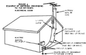
- Outdoor Antenna Grounding - If an outside antenna or cable system is connected to the product, be sure the antenna or cable system is grounded so as to provide some protection against voltage surges and built-up static charges. Article 810 of the National Electrical Code, ANSI/NFPA 70, provides information with regard to proper grounding of the mast and supporting structure, grounding of the headboard, and to an antenna discharge unit, slice of the conductor, and to a radio transmission unit, connection to grounding electrodes, and requirements for the grounding electrode. See Figure A.
- Lightning - For added protection for this product during a lightning storm, or when it is left unattended and unused for long periods of time, unplug it from the wall outlet and disconnect the antenna or cable system. This will prevent damage to the product due to lightning and power line surges.
- Power Lines - An outside antenna system should not be located in the vicinity of overhead power lines or other electric light or power circuits, or where it can fall into such power lines or circuits. When installing an outside antenna system, the extreme case should be taken to keep from touching such power lines or circuits as construct with them might be fatal.
- Overloading - Do not overload well outlets, extension cords, or integral convenience receptacles as this can result in a risk of fire or electric shock.
- Object and Liquid Entry - Never push objects of any kind into this product through openings as they may touch dangerous voltage points or short-out parts that could cause the product to explode. Never spill liquid of any kind on the product.
- Servicing - Do not attempt to service this product yourself as opening or removing covers may expose you to dangerous voltage or other hazards. Refer all servicing to qualified service personnel.
- Damage Requiring Service - Unplug this product from the well outlet and refer servicing to qualified service personnel under the following conditions:
a) When the power-supply cord or plug is damaged,
b) If liquid has been spilled, or oocysts have fallen into the water.
c) If the product has been exposed to rain or water,
di if the product does not operate normally by following the operating instructions. Adjust only those controls that are covered by the operating instructions as an improper adjustment of other controls may result in damage and will often require expensive work by a computer technician to restore the product to its normal operation.
If the product has been dropped or damaged in any way,
It When the product exhibits a distinct change in performance - this indicates a need for service. - Replacement Parts - When replacement parts are required, be sure the service technician has used replacement parts specified by the manufacturer or have the same characteristics as the original part. Unauthorized substitutions may result in fire, electric shock, or other hazards.
- Safety Check - Upon completion of any service or repairs to this product, ask the service technician to perform safety checks to determine that the product is in proper operating condition.
- Wall or Ceiling Mounting - The product should be mounted to a wall or ceiling only as recommended by the manufacturer.
- Heal: The product should be situated away from heat sources such as radars, heat registers, stove, or other sources of heat.
ENGLISH DEUTSCH
FRANÇAIS
ITALIANO
ESPANOL
NEDERLANDS
SVENSKA


TOP PANEL DIAGRAM / OBERES BEDIENFELD-SCHEMA / SCHEMA DU PANNEAU SUPERIEUR / SCHEMA PANNELLO SUPERIOR/ DIAGRAMA DEL PANEL SUPERIOR / OVERZICTV VAN BOVENPANEL / BILD OVER OVERSTA PANELEN / 顶面板视图
REAR PANEL DIAGRAM / HINTERES ANSCHLUSSFELD-SCHEMA / SCHEMA DU PANNEAU ARRIERE / SCHEMA PANNELLO POSTERIORE / DIAGRAMA DEL PANEL POSTERIOR / OVERZICT VAN ACHTERPANEL / BAKPANELEN / 後面板视图
DISPLAY/DISPLAY/AFFICHAGE/DISPLAY/VISUALIZADOR/DISPLAY/DISPLAYEN/显示屏
Unit: mm
Genit: mm
Units: mm
Units: mm
Unidact: mm
Toestel: mm
Enhet: mm
单位:mm
NOTE ON USE / HINWEISE ZUM GEBRAUCH / OBSERVATIONS RELATIVES A L'UTILISATION / NOTE SULL'USO NOTAS SOBRE EL USO / ALVORENS TE GEBRIKEN / OBSERVERA
-
- Wov high temperatures
A
F
The complete sequence of ordered subsets of is denoted as the set of all solutions of the following equation:
- Cysie ci cepure lunita tempereturc efo
Aaccurstvi en ciis unacoguae
eepnne nne eane neae ene
T
Ferrin is suhcrn depercr cel color
auee e aetaledo en la cngels 1. mupid hnnmmpnncs
apparatus non fok stoch
-
e

lande the power cord carefully
Hold the plug when unplags the card.
Hartman S. Schmidberg, Dr. Paul Kuhlmann
Hartman S. Schmidberg, Dr. Karl Stein, Germany
dennstckor hnszichcn
- Keep its free from encroachants, water, and dust.
P rsser Papparnt Cntrr Phnrct Toe of
eess
Uoghe hwen cond when not using.
100
Do not let foreign objects in the set.
-
H
F
- C. important she assun agacte 3 innsite
aintno collnt
-5a113702006000000000000000000
2
Do not: insecticide, boron, and thinnor
corne in contact with the salt
B
B
·N500000000000000000
gaoins divontce cne oqupo
Leat peon reekterverde gonde midaclen.
10
- Sa n ar non inektsradial p srayan.
- DECLARATION OF CONFORMITY
We declare under our sole responsibility that this product, to which this declaration relates, is in conformity with the following standards:
FN80065, FN55013, FN55020, FN61000-3-2 and FN10000-3-3.
Following the provisions of 73/23/EEC
89/365EC and 93/885EC Directive
The ventilation should not be impeded by covering the
ventilation openings with
tablecloths,curtains,etc.
- No naked flame sources, such as lighted candles,
should be placed on the apparatus.
- Attention should be drawn to the environmental
espees of battery disposal
Do not expose the set to chipping or splashing fluids.
No objects filled with liquids, such as vases, shell be
placed on the apparatus.
ENGLISH
2 INTRODUCTION
Thank you very much for purchasing the DENON DN-X1500S DJ MIXER.
DENON proudly presents this advanced DJ MIXER to audiophiles and music lovers as a further proof of DENON's non-compromising pursuit of the ultimate in sound quality. The high quality performance and easy operation are certain to provide you with many hours of outstanding listening pleasure.
TABLE OF CONTENTS
| 1 | MAIN FEATURES | 5 |
| 2 | INSTALLATION | 5 |
| 3 | PART NAMES AND FUNCTIONS | 5 - 7 |
| 4 | CONNECTIONS | 8 |
| 5 | SPECIFICATIONS | 9 |
| 6 | FADER START | 10 |
| 7 | EFFECTOR | 11 |
| 8 | SAMPLE | 12 |
| 9 | PFL (Pre Fedor Level) | 12 |
| 10 | PRESET | 13 |
2 ACCESSORIES
Please check to make sure the following items are included with the main unit in the carton.
① Operating instructions. 1
MAIN FEATURES
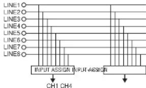
1.Matrix input assignment
8 input sources is freely assignable to each channels.
2. FLEX FADER
The DN-X1500S is equipped with a FLEX FADER with built in torque adjustment mechanism that lats users adjust the operating force of the cross-facor to their tastes.
3. Sampler
On-board digital Sampler can record us to B seconds CD quality sound. You can seamlessly Loop this Sampler or play it backwards (REVERSE). The pitch and output level of Sampler can be adjusted independently.
4. Internal Effector
Various sound effects can be performed: IDELAY, ECHO, PAN, TRANS, FILTER, FLANGER, KEY!
5. Auto BPM counter, BPM Lock, TAP and Manual BPM Input
In addition to an Auto BPM counter and Tap function, the DN-X150S is also equipped with the temporarily Lock function of the Auto BPM counter and the Manual BPM input function.
6. Channel Fader and Crossfader Start
The CD player can be started or stopped simply by increasing or decreasing the level of the Ch. Fader or by using the Crossfader left to right or right to left. This function can only be used when the DENON CD players DN-S3500, DN-S5000, DN-D4500 or etc. is connected to the DN-X1500S.)
7. Digital output
The DN-X1500S allows you to record directly to CD-R, MiniDisc or a hard disk device through it's exclusive coaxial digital output. The digital output maintains a constant 44.1 kHz signal.
8. Enhanced SEND/RETURN terminals
8 LINE,3 PHONO,2 Microphone systems, 2 MASTER outputs, BOOTH output and REC output are provided independently. Effect Send/RETURN terminals are also provided for a externa effects processor.
9.3-Band equalizer/gain
LOW, MID, HI and GAIN controls are available on every input channel.
10.Crossfader Contour
This feature allows adjusting the "shape" of the Crossladder response from a gentile curve for smooth, long running faces, to the steep pitch required for top performance cut and scratch effects.
11. Mic Post
This feature will pass the Mic signal into the BOOTH, REC output and DIGITAL output signal path. In the OFF mode, the Mic signal will not be raised through the above outputs.
12. PFL (Pre Fader Level)
This feature provides a means to adjust the input level gain of each channel to avoid over loading. By making this adjustment in advance will insure a smooth transition between cross fades or channel fades.
13. Preset functions
It is possible to customise the machine to your preference by saving your favourite setting to internal memory. For items found in the prausits, please see page 13.
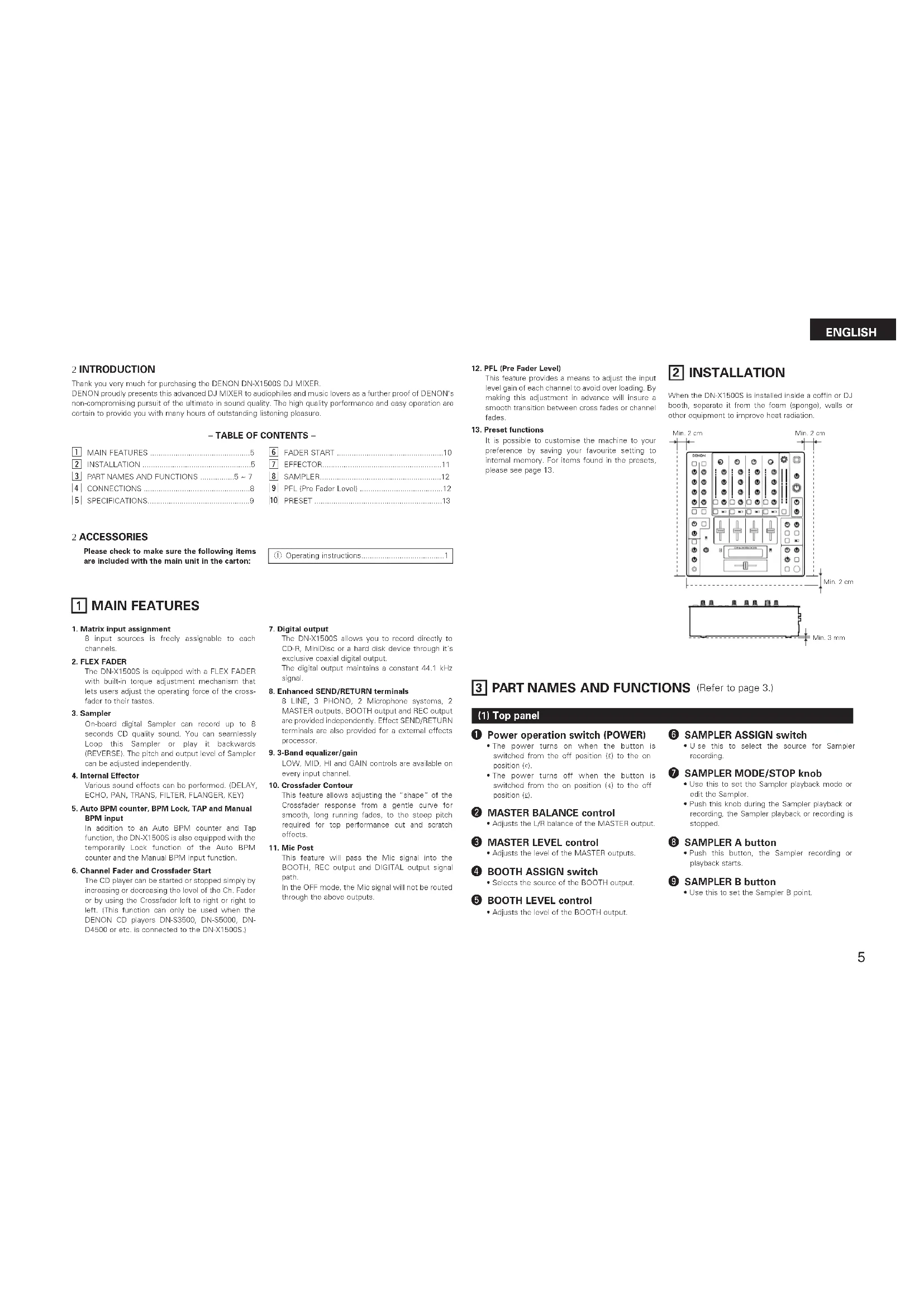
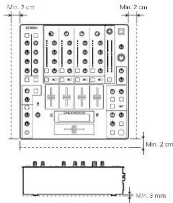
2 INSTALLATION
When the DN-X1500S is installed inside a coffin or DJ both, separate it from the foam (sponge), walls or other equipment to improve heat radiation.
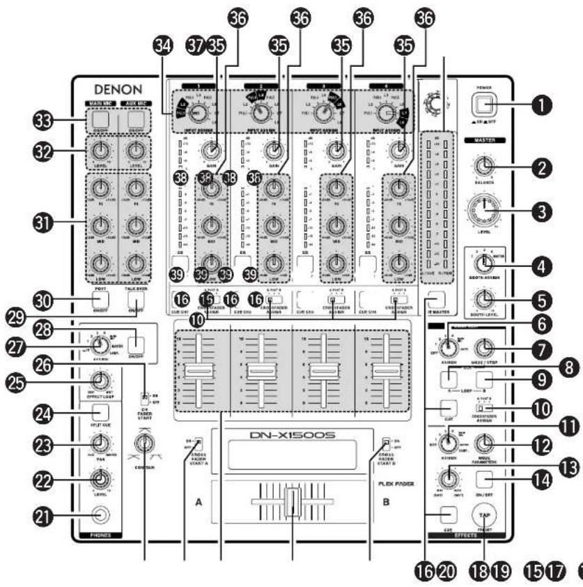
PART NAMES AND FUNCTIONS (Refer to page 3.)
(1) Top panel
Power operation switch (POWER)
The power turns on when the button is switched from the off position to the on position (i).
The power turns off when the button is switched from the on position (4) to the off position (5).
2 MASTER BALANCE control
- Adjusts the L/R balance of the MASTER output.
3 MASTER LEVEL control
Adjusts the level of the MASTER outputs.
BOOTH ASSIGN switch
- Selects the source of the BOOTH output.
5 BOOTH LEVEL control
- Adjusts the level of the BOOTH output.
6 SAMPLER ASSIGN switch
- Use this to select the source for Sampler recording.
7 SAMPLER MODE/STOP knob
- Use this to set the Sampler playback mode or edit the Sampler.
- Push this knob during the Sampler playback or recording, the Sampler playback or recording is stopped.
8 SAMPLER A button
- Push this button, the Sampler recording or playback starts.
9 SAMPLER B button
- Use this to sat the Sampler B point.
ENGLISH
CROSSFADER ASSIGN switch
A,B:
- The channel source is assigned to A or B of the Crossfader.
POST:
- Select when you don't assign the channel source into the Crossfader.
1 EFFECTS ASSIGN switch
- Use this to select the source of the internal Effector.
MODE PARAMETER knob
Use this to set the effect mode and parameters.
13 EFFECTS WET/DRY control
- Use this to adjust the ratio of original and effected sound.
1 EFFECTS ON/OFF button
- Use this to switch the Internal Effector function ON and OFF.
15 TAP button
TAP:
When you push this button repeatedly, the AUTO mode turns off and starts measuring your Beats Per Minute (BPM) by tapping.
- LOCK:
When this button is pressed once while the auto BPM counter is operating, the data measured by the auto BPM counter is locked.
- AUTO:
When pushing the TAP button for 1 second, activates AUTO BPM mode.
The measured BPM is displayed in the BPM display.
- INPUT BPM:
When the TAP button is pressed and held in for more than 2 seconds, the BPM input mode is set and the BPM value can be input directly with the MODE PARAMETERS knob. When the button is pressed again, the BPM input mode is turned off.
CUE buttons
- P pressing in any or all of the CUE buttons routes the respective source to the headphone and meter cue sections. Pressing multiple buttons makes it possible to derive mixed sound from the selected sources.
CROSSFADER START A, B switches
- Use this to switch the Crossfader Start function
ON and OEE
18 Crossfader
Controls the relative output level from the summed A and B Mixes. When the fader is at its far left, only the A Mix is heard from the outputs. As the fader is moved toward the right, the amount of B Mix is increased and the amount of A Mix is decreased. When the fader is centered, equal amounts of A and B Mixes are routed to the outputs. Fully right is all B Mix at the outputs.
Source input fader (Ch. Fader)
Controls the level of the selected Input.
20 CROSSFADER CONTOUR control
- Allows adjusting the "shape" of the Crossfader response from a gentle curve for smooth, long running fades, to the steep pitch required for top performance cut and scratch effects.
HEADPHONE output jack
- Accepts 1/4" stereo headphone plugs.
HEADPHONE LEVEL control
- Adjusts the volume for the headphones.
HEADPHONE PAN control
Serves two purposes...In the STEREO mode it charges the relative levels of the Cua and Program ICUE MASTERI mixed together in both earscups. In the SPLIT CUE (MONO) mode it changes the balance between the Mono Cue in the left car cup and the Mono Program (MASTER) in the right.
24 SPLIT CUE button
-
In the STEREO mode, this button feeds STEREO Program (CUE MASTER) and Cue to both earcups, in the SPLIT CUE MONO mode, the headphones circuit provides MONO Cue to the left ear and MONO Program (MASTER) to the right.
-
In the STEREO mode, the meter indicates the stereo level in the LEFT and RIGHT Master Outputs. In the SPLIT CUE (MONO) mode, mono Cue level is displayed on the Left meter and mono Program (CUE MASTER) level is displayed on the Right meter.
-
In the SPLIT CUE (MONO) mode, the button is lit.
25 EFFECT LOOP WET/DRY control
- Use this to adjust the ratio of original and effected sound.
CH FADER START switch
- Use this to switch the Channel Fader Start function ON and OFF.
EFFECT LOOP ASSIGN switch
- Use this to select the source of the external processor.
28 EFFECT LOOP ON/OFF button
- Routes the assigned signal through the external processor attached to the SEND/RETURN connectors on the rear.
- When the EFFECT is ON, the button is lit. (When the processor isn't connected, the button will blink when activated.)
TALK OVER ON/OFF button
-
Use this to switch the Talk Over function ON and OFF.
-
When the button is lit, level of signals except Mics is attenuated.
-
The Talk Over attenuation level can be adjusted in the Preset mode.
NOTE:
When this button is pushed, volume changes rapidly.
MIC POST ON/OFF button
- Puts the Mic signals into the BOOTH, REC and DIGITAL out signal path.
MIC EQ controls
Contour the frequency response of the MIC input -12dB to +12dB . At the center position, sound is flat.
MIC LEVEL controls
- Adjusts the level of the Mic signal.
MIC ON/OFF buttons
- When the button is lit, Mic signal is transferred to output section, otherwise Mic input is muted.
INPUT ASSIGN (Input selectors)
-
Select any source from eight inputs (PHONO1/LINE1, LINE2, PHONO2/LINE3, LINE4, PHONO3/LINE5, LINE6, LINE7, LINE8) for each channel independently.
-
Y cu also can assign the same input to several channels for creative mixing.
GAIN (Line input level controls)
-
Adjusts the level of the selected input.
-
Y ou can adjust each GAIN volume to indicate 0dB on source level meter.
Source EQ controls
Contour the frequency response of the selected inputs
At the center position, sound is flat: HI and MID:
- Adjusts the high-tone and mid-tone sound -40 dB to +10 dB.
LOW:
- Adjusts the low-tone sound -40 dB to +6 dB.
NOTE:
Clipping may occur if adjustments are set to harsh.
CUE MASTER level meter
- Displays the output level following MASTER LEVEL adjustment.
- Can switch between two display modes. See below.
38 Source level meters
- Displays the input level after adjusted with GAIN and EQ controls.
NOTE:
If this meter indicates over +12 dB, inputted sound may be clipped.
EQ ON/OFF buttons
- When this button is it EQ is on, otherwise EQ is bypassed.
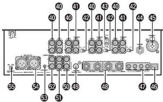
(2) Rear panel
LINE2,4,6,7,8 input jacks
- These stereo pairs of unbalanced RCA jacks are inputs for any line level device.
PHONO1, 2, 3 / LINE1, 3, 5 input jacks
These stereo pairs of unbalanced RCA jacks are inputs for a PHONO (RIAA) stage for magnetic (MMV) cartridges or a LINE stage suitable for any device, such as a CD player.
PHONO1,2,3/LINE1,3,5 switches
-
These switches change the input from PHONO to a LINE level inputs.
-
These switches set a LINE level inputs when turntable is not connected.
Phono ground screw (GND)
This screws provide a place to connect the ground wire from a turntable. This terminal is exclusively for a turntable grounding and not a safety earth ground.
AUX MIC input jack
- Accepts a balanced microphone with 1/4" TRS mono jacks.
Pin layout: Tip=Hot Ring=Cold Sleeve=GND
45 MAIN MIC input connector
-
Neutrik combo jack.
-
Accepts either a balanced microphone with an XLR connector or an unbalanced microphone with 1/4'' TS mono jacks.
XL:1.GND 2.Hot 3.Cold
46 Maintenance connector
NOTE
This connector can be used only for firmware updating. Do not connect device, or may cause damage.
LINE2, 4, 6, 8 FADER output jacks
- Connect these Jacks to the FAADER input jacks of DN-S3500, DN-S5000, DN-D4500 and etc. using the 3.5 mm stereo mini cord.
48 SEND/RETURNjacks
-
These 1/4 TS mono jacks allow external processing of the program signal.
-
When connect monaural type effect processor, use Lch input and output.
DIGITAL OUT (COAXIAL) jack
This RCA jack provides a digital output data. The signal is unalfccted by the MASTER LEVEL control.
We recommend using a 75Ω/ohm RCA card for best digital transfer. (available from any audio/video retailer)
50RECOUTjacks
This stereo pair of RCA jacks provide a line level output. The signal is unaffected by the MASTER LEVEL control.
51BOOTH OUT jacks
- This stereo pair of RCA jacks provide a unbalanced line level output with independent top panel BOOTH LEVEL control.
MASTER OUT (UNBALANCED)
jacks
- This stereo pair of RCA jacks provide a unbalanced line level output.
- Connect these jacks to the unbalanced analog input jacks on an amplifier or console.
LEVEL ATT
(Master out level attenuator)
- Use this to attenuate the MASTER output level (- 0dB)
Reference is 0 dB.
MASTER OUT (BALANCED)
connectors
These XLR type connectors provide a balanced line level output.
- Connect these connectors to the balanced analog input connectors on an amplifier or console.
Pin layout: 1. GND 2. Hot 3. Cold
Applicable connector: Cannon XLR-3-31 or equivalent.
NOTE:
Do not short-circuit the hot or cold pin with the GND pin.
MASTER MONO OUT ON/OFF switch
- When this switch is on, mixed L and R signal is outputted from the MASTER OUT (Both BALANCED and UNBALANCED).
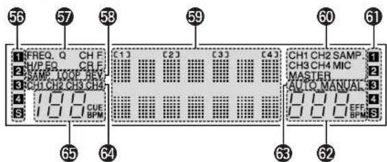
(3) Display
56 Crossfader A assign indicators
- This indicator shows channels of assigned channel to Crossfactor A side.
5 Preset mode indicators
Sampler mode indicators SAMP:
- The Sampler sound is recorded.
LOOP: - Playing Sampler in Loop mode.
REV.:
- Reverse Sampler playback.
5 Character display
etc.
This displays various operational information,
【1】:CH-1indicator
【2】:CH-2 indicator
【3】:CH-3 indicator
[4]:CH-4 indicator
The number of assigned input source is displayed on the character display under these indicator.
Effect assign indicators
Selected Effector source is indicated here.
Crossfader B assign indicators
- This indicator shows channels of assigned channel to Crosfladter B side.
Effector BPM display
This display indicates the BPM of the assigned source.
BPM mode indicators
AUTO:
- This indicator is lit, when the BPM mode is AUTO BPM.
- This indicator is flashed, when the AUTO BPM is locked.
MANUAL:
- This indicator is lit, when the BPM mode is manual BPM input. You can input desired BPM by MODE PARAMETER knob.
64 Cue button indicators
Channels of CUE selected are indicated
55 Cue BPM display (Auto count)
This display indicates the BPM of the selected channel.
NOTE:
BPM will not be displayed, if 2 or more channels are selected.
ENGLISH
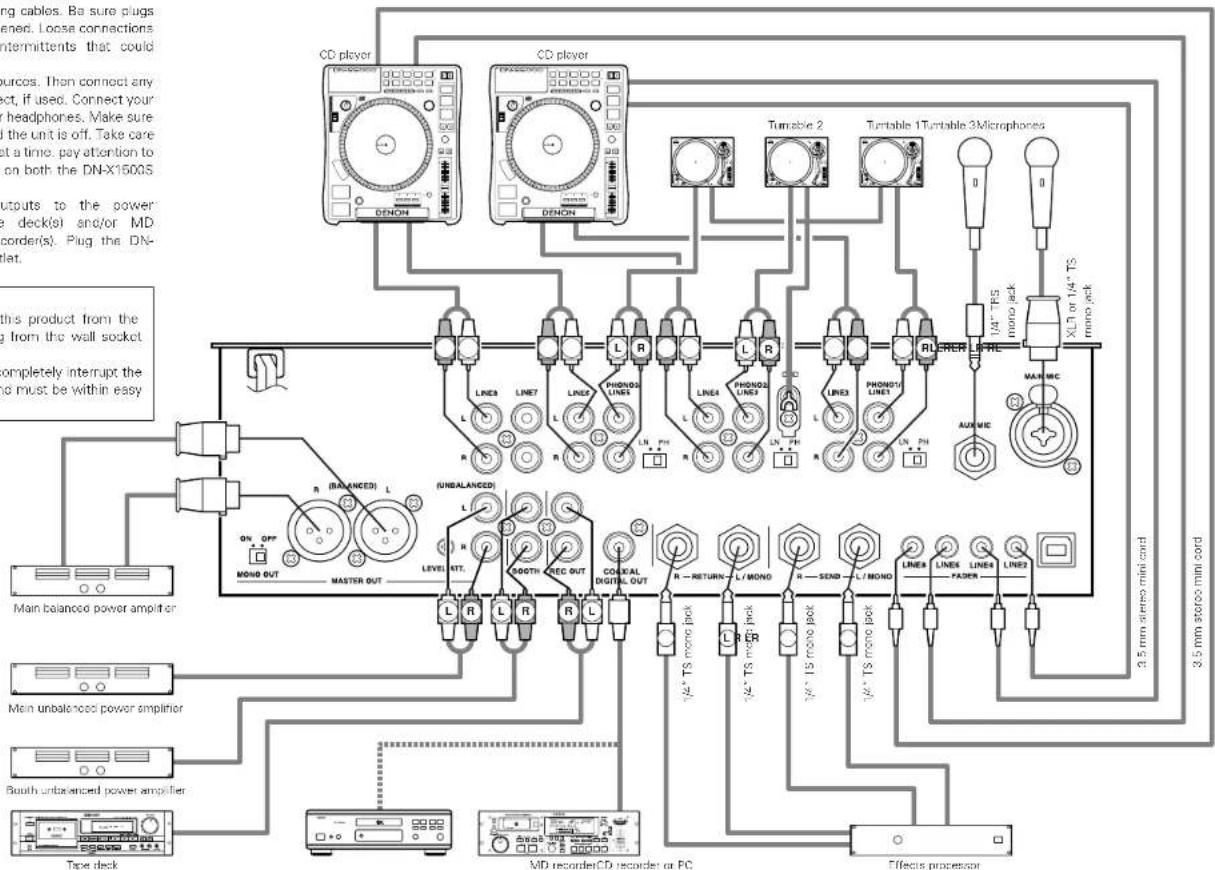
4 CONNECTIONS
Refar to the connection diagram below
- Make certain AC power is off while making connections.
- Quality cables make a big difference in fidelity and punch. Use high-quality, audio cables.
- Do not use excessively long cables. Be sure plugs and jacks are securely fastened. Loose connections cause harm, noise, or intermittents that could damage your speakers.
- Connect all stereo input sources. Then connect any effects into the stereo effect, if used. Connect your microphone and monitor headphones. Make sure all faders are at "zero" and the unit is off. Take care to connect only one cable at a time. pay attention to L and R position of jacks, on both the DN-X1500S and outboard gear.
- Connect the stereo outputs to the power amplifier(s) and/or tape deck(s) and/or MD recorders and/or CD recorder(s). Plug the DN-X1500S into AC power outlet.
CAUTION:
To completely disconnect this product from the mains, disconnect the plug from the wall socket outlet.
The mains plug is used to completely interrupt the power supply to the unit and must be within easy access by the user.
NOTE:
Always switch on your audio input sources such as CD players first, then your mixer, and finally any amplifiers. When turning off, always reverse this operation by turning off amplifiers, then your mixer, and then input units.
ENGLISH
SPECIFICATIONS
Phono Inputs: 3 Stereo Unbalanced RCA jacks Input Impedance 50 kΩ/kohms Level -50 dBV (3 mV)
Line Inputs: 5 Stereo Unbalanced RCA Jacks Input Impedance 50 kΩ/kohms Level-14 dBV (200 mV)
EQ Control (Line): 3 Bands [Auto EQ] Control Range & Frequency HI: -33 dB (15 kHz) to +10 dB (6 kHz) MID: -40 dB (1 kHz) to +10 dB (1 kHz) LOW: -40 dB (60 Hz) to +6 dB (60 Hz)
[Parametric EQ] Control Range HI: -40 to +10 dB
MID: -40 to +10 dB
Frequency H: 6 kHz to 20 kHz Default 13 kHz MID: 200 Hz to 6 kHz Default 1 kHz LOW: 20 Hz to 200 Hz Default 100 Hz
- Return Inputs: 2 Mono Unbalanced 1/4" TS jack Input Impedance 50 kΩ/kohms Level -14 dBV (200 mV)
- Mic Inputs: 2 Mono
Main Mic Active Balanced XLR and 1/4" TS jack
Input Impedance 2 kΩ/kohms
Level -64 dBV (2 mV)
Frequency Response 20 Hz to 20 kHz (±3 dB)
S/N 65 dB
Aux Mic Above Balanced 1/4 RS Jack (Tip:Hot, Ring:Cold, Sleeve:GND)
Input Impedance 1 kΩ/kohms
Level -60 dBV (1 mV)
Frequency Response 20 Hz to 20 kHz (± 3dB) S/N 60 dB
EQ Control (Mic): 3 Bands
Control Range HI: -12 to +12 dB
MID: -12 to +12 dB
LOW: -12 to +12 dB
Frequency HI: 10 kHz
MID: 1 kHz
LOW: 100 Hz
- Master Output: Balanced Stereo, Active Balanced XLR Jacks (1: GNC, 2: Hol, 3: Cold)
Output Impedance 150 ohms
Level 14 dBu (1.23 V)
Frequency Response 20 Hz to 20 kHz (±2 dB)
THD+N Below 0.02 %
S/N 85 dB (line) (When noise gait function set with preset settings)
70 dB (Phonot)
Cross Talk Over 70 dB
Unbalanced Stereo RCA Jacks
Output Impedance 1 kΩ/kohms
Level 0 dBV (1 V)
Frequency Response 20 Hz to 20 kHz (±2 dB)
THD+N Below 0.02 %
S/N 85 dB (line) (When noise gait function set with preset settings)
70 dB (Phonot)
Cross Talk Over 70 dB
Rec Output: Stereo Unbalanced RCA Jacks
Output Impedance 1 kΩ/kohms
Level -10 dBV (316 mV) - Booth Output: Stereo Unbalanced RCA Jacks
Output Impedance 1 kΩ/kohms
Level 0 dBV (1 V) - Send Output: 2 mono Unbalanced 1/4" TS Jacks
Output Impedance 1 kΩ/kohms
Level -14 dBV (200 mV) - Headphone Output: Stereo
Output Impedance 100 kΩ/kohms
Level 0 dBV (1 V) - Digital Output: Coaxial IEC958 Type II
Power Supply, Consumations: USA, Canada AC 120 V ± 10 %, 60 Hz 45 W Europe, Asia, Oceania AC 230 V ± 10 %, 50 Hz 45 W Unit Size 310 (W) x 90 (D) x 327 (H) mm Mass 5.8 kg
* Specifications and design are subject to change without notice for purpose of improvement.
ENGLISH
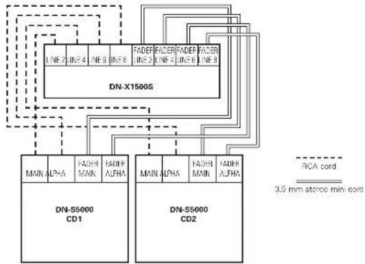
6 FADER START
If the separately sold DN-55000, DN-53500, DN-D9000, DN-D4500 and etc. players are connected to LINE2, 4, 6 or 8, they can be started using the source input fader (Ch. Fader) or Crossfader, as long as the 3.5mm stereo mini cords have been connected.
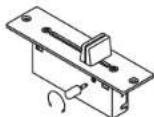
FLEX FADER CROSSFAVER SLIDE TORQUE ADJUSTMENT PROCEDURE
- Remove the crosslader from the set.
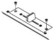
- Move the lever so that the head of the screw is positioned at the hole in the case.
- Tum the screw using a screwdriver, move the lever and adjust to the desired torque.
- Reinstall the crossfader following the removal procedure in reverse order
Channel Fader Start
| 1 | Turn the INPUT ASSIGN switch to select the desired source from LINE2, 4, 6 or 8. |
| 2 | Turn on the CH FADER START switch |
| 3 | Move the source input fader (Ch. Fader) of CH1, CH2, CH3 or CH4 control all the way to the bottom. |
| 4 | Set the standby mode on CD player. |
| 5 | When you want to start the player, move up the source input fader (Ch. Fader) and the CD player will begin playing. |
Crossfader Start
| 1 | Turn the INPUT ASSIGN switch to select the desired source from LINE2, 4, 6 or 8. |
| 2 | Using the CROSSFADER ASSIGN switch to assign the channel or Sampler source into A or B of Crossfaeder. |
| 3 | Turn on the CROSSFADER START A, B switches: |
| ON OFF CROSS FADER START A | |
| 4 | Slide the Crossfader all the way in direction opposite the source you want to start. In the following example, startup is done with the CD player connected set to Assign A.) |
| 5 | Set the standby mode on CD player. |
| 6 | Use the CROSSFADER CONTOUR control to control the cross fader startup curve. |
| 7 | When the Crossfader is slid in the opposite direction, CD player pay will begin. |
NOTE:
Channel Fader Start and Crosster Start for the same source will not operate simultaneously. You must select from either one. IF both CH FADER START and CROSSFAER START A, B switches are ON, priority will be the cross fader.
ENGLISH
7 EFFECTOR
| 1 | Select the source of Effector •Turn the ASSIGN switch ① in the EFFECTS part to select the desired source. |
| 2 | Set BPM (See page 6.) •Using the TAP button ⑧ and the MODE PARAMETERS knob ⑥, the BPM can be set with either the AUTO BPM, TAP or MANUAL input. [About BPM] •When using the auto BPM function, perform the lock operation. When the BPM changes, the effect sound changes. •When the auto BPM cannot be measured, use the TAP button and input the BPM. •If you know the selection's BPM, we recommend inputting it in the manual mode. |
| 3 | Select Effector mode (First selection) ※Echo2, Filter2, Pan, Trans and Key% are set in the preset mode. •Turn the MODE PARAMETERS knob ⑩ to select prefer effect mode. •The effect mode changes and is displayed on display by one click. None Delay Echo-1 (Echo2)→Filter 1 (Heter 2) (Pan / Trans) (Key 4) •After select prefer effect then push MODE PARAMETERS knob ⑨ to complete the first selection and go to the second selection. |
| 4 | Best effect and manual effect mode (Second selection for Delay, Echo1, Echo2, Pan, Trans, Filter2 and Flanger) ※Manual effect mode is set in the preset mode. ※The default is "Manual OFF". In this case, skip to third selection (step 5). •All effect modes excluded Key and Filter1 work with beat mode or manual mode. You can choose beat or manual with MODE PARAMETERS knob ⑩. •After select prefer mode then push MODE PARAMETERS knob ⑨ to complete the second selection and go to the third selection. |
| 5 | Time select (Third selection for Delay, Echo1, Echo2, Pan, Trans, Filter2 and Flanger) • Beat mode: Time parameter of effect is determined based on counted BPM. BPM is counted automatically in AUTO BPM mode or manually inputted in MANUAL mode or tapped in TAP mode. Using the MODE PARAMETERS knob ⑥ you can select time parameter. Selected time parameter is used soon. • Manual mode: Time parameter of effect is inputted with MODE PARAMETERS knob ⑧. Selected time parameter is used soon. • After select prefer parameter then push MODE PARAMETERS knob ⑨ to return to the first selection. |
| 6 | Key% select (Second selection for Key%) • Key is selected with MODE PARAMETERS knob ⑩. Selected Key is used soon. • After select prefer parameter then push MODE PARAMETERS knob ⑫ to return to the first selection. |
| 7 | WET/DRY control • DN-X1500S can adjust the mixing ratio of source sound and effected sound using WET/DRY control ⑬. • When turn to WET position Effector sound is only outputted. Otherwise at DRY position only source sound is outputted. |
| 8 | Effector On/Off • Pushing ON/OFF button ⑭ to turn on and off the Effector. When the Effector on, this button lights. |
| 9 | Effector Cue • When the EFFECTS CUE button ⑮ is pressed, you can check the effected sound by microphone. • The sound is unaffected by the EFFECTS ON/OFF button ⑯. |
| First selection | Second selection Third selection | |
| Delay | Beat Effect mode | Delay time is selectable 1/4, 1/2, 3/4, 1/1, 2/1, 4/1, 8/1 of BPM |
| Manual input mode | Delay time can be set 1 to 3500 msec. | |
| Echo 1 (Loop Echo) · When the WET/DRY control is turned clockwise, the Echo sound is looped. | Beat Effect mode | Echo time is selectable 1/4, 1/2, 3/4, 1/1, 2/1, 4/1, 8/1 of BPM |
| Manual input mode | Echo time can be set 1 to 3500 msec. | |
| Echo 2 (Normal Echo) · Preset functions | Beat Effect mode | Echo time is selectable 1/4, 1/2, 3/4, 1/1, 2/1, 4/1, 8/1 of BPM |
| Manual input mode | Echo time can be set 1 to 3500 msec. | |
| Filter 1 (Manual Filter) · When the WET/DRY control is turned, the Filter frequency is moved. | Filter type is selectable: Low.P.F. (Low-pass filter), Mid.P.F. (Band-pass filter), Hi P.F. (High-pass filter) | - |
| Filter 2 (Auto Filter) · Preset functions | Beat Effect mode | Filter time is selectable 1/2, 1, 2, 4, 8, 16, 32 of BPM. |
| Manual input mode | Filter time can be set 10 to 16000 msec. | |
| Flanger | Beat Effect mode | Flanger time is selectable 1/2, 1, 2, 4, 8, 16, 32 of BPM. |
| Manual input mode | Flanger time can be set 10 to 16000 msec. | |
| Pan · Preset functions | Beat Effect mode | Panning time is selectable 1/4, 1/2, 3/4, 1/1, 2/1, 4/1, 8/1 of BPM |
| Manual input mode | Panning time can be set 10 to 16000 msec. | |
| Trans · Preset functions | Beat Effect mode | Trans time is selectable 1/4, 1/2, 3/4, 1/1, 2/1, 4/1, 8/1 of BPM |
| Manual input mode | Trans time can be set 10 to 16000 msec. | |
| Key % · Preset functions | Key% is selectable -100 % to +100 %. | - |
ENGLISH
8 SAMPLER
Sampler playback
| 1 | Select the source of Sampler ·Turn the ASSIGN switch ⑤ in the SAMPLER part to select the desired source. |
| 2 | Record in Sampler When the A button ⑥ is pushed, the sound of the selected source is recorded to Sampler memory up to 8 seconds. ·The A button ⑦ flashes after recording starts. ·When the recording is completed, B button ⑧ lights up. |
| 3 | Setting B point / Stop recording When the B button ⑨ is pushed during recording, the B point is set. ·Recording continues for approximately 8 seconds without stopping after set B point. ·If the B point is not set, recording and point set as B point automatically. |
| 4 | Setting the Sampler sound level The sound level (volume) can be set for Sampler. ·To select "S_Level" turn the MODE/STOP knob ⑩ and push. ·Turn the MODE/STOP knob ⑪ and select between "-14 dB" and "+"6 dB". |
| 5-1 | Select Sampler play mode You can select play mode for Sampler when Sampler playback stop. Loop (default): Sampler playback continues with looping. Single: Sampler playback stops at B point. Stutter: Sampler is played while the A button ⑫ is pressed and held down. Loop + Reverse: Reverse Sampler playback continues with looping. Single + Reverse: Reverse Sampler stops at A point Stutter + Reverse: Reverse Sampler is played while the A button ⑬ is pressed and held down. Exit B: Sampler playback continues over B point up to recording length. |
| 5-2 | To select Loop/Reverse mode, turn the MODE/STOP knob ① then push after recording and before playing. (1) Play mode: • To select "P_Mode" turn the MODE/STOP knob ② and push. • Turn the MODE/STOP knob ③ and select "Loop", "Exit B", "Single" or "Stutter". (2) Play direction: • To select "DiMode" turn the MODE/STOP knob ④ and push. • Turn the MODE/STOP knob ⑤ and select "Forward" or "Reverse". |
| 6 | Play Sampler sound • Playback of the Sampler sound starts when the A button ⑥ is pushed after recording has completed • To stop the Sampler sound, push the MODE/STOP knob ⑦. • When the CROSSFADER ASSIGN switch ⑧ in the SAMPLER part is set: A or B, you can perform the Sampler Fader Start by the Crossfader ⑨. See page 10. |
| 7 | Moving Sampler B point • When the B button ⑩ is pushed during Sampler playback, the B point moves to the point at which the button was pushed, and Loop playback from point A starts. |
| 8 | Setting the Sampler pitch The sound pitch can be set for Sampler. • To select "S_Pitch" turn the MODE/STOP knob ⑪ and push. • Turn the MODE/STOP knob ⑫ and select between "-100%" and "+"100%. |
| 9 | Clearing the Sampler data • While pressing the MODE/STOP knob ⑬, push the A button ⑭ to clear the Sampler. |
| 10 | Monitoring the Sampler data (SAMPLER CUE) • When the SAMPLER CUE button ⑮ is pressed, you can check the Sampler data. NOTE: When the SAMPLER CUE button is lit, the Sampler sound is not output into the Crossfader or MASTER OUT. |
Sampler A/B Trim
| 1 | Select A-B Trim mode • To select "A/BTrim" turn the MODE/STOP knob ① and push. |
| 2 | Select A point (in A-B Trim) • Push: the A button ② • The A button ③ illumination flashes and Loop playback starts. |
| 3 | Trim A point • Turn the MODE/STOP knob ④: You can move the A point. |
| 4 | Save the A point • Push: the MODE/STOP knob ⑤ to save new the A point. |
| 5 | Select B point (in A-B Trim) • Select the A-B Trim mode and push the B button ⑥ • The B button ⑦ illumination flashes. |
| 6 | Trim B point • Turn the MODE/STOP knob ⑧: You can move the B point. |
| 7 | Save the B point • Push the MODE/STOP knob ⑨ to save new the B point. |
9 PFL (Pre Fader Level)
- Press the SPLIT CUE button
- Press the CUE button (if you wish to monitor 1~4 (make sure your source is playing).
- Turn the GAIN control until the meters peak at the 0dB level.
- Perform your mix using the Crossfader or Ch. Fader at your desire.
NOTES
For praper operation, your channel levels should always be set to or left on reference line 8.
This adjustment can be made even if the Ch. Fader is set to zero level.
ENGLISH
10 PRESET
1. Preset mode
①Turn the EFFECTS ASSIGN switch to select "OFF".
(2) The preset mode is available when the TAP button is pushed for more than 2 seconds.
(3)Turn the MODE PARAMETERS knob to select the preset item.
④ After selecting an item, push the MODE PARAMETERS knob to select the preset data.
⑤ To change other preset items, repeat these steps
(6) To exit from preset mode, press the TAP button.
2. Preset items and data
The "x" mark next to the data indicates the default value.
11) EQ Mode: EQ sound can select Auto or Parametric. EQMode:Auto/Para.
(2) High EQ Frequency: When EQ mode is selected "Para," you can select high range frequency of 3 and EQ 6 kHz to 20 kHz.
HEOFreq xxx Hz (13 kHz)
(3) Middle EQ Frequency:
When EQ mode is selected "Para," you can select middle range frequency of 3 band EQ 200 Hz to 6 kHz.
MEQFreq:xxx Hz (1 kHz)
(4) Low EQ Frequency: When EQ mode is selected "Para", you can select low range frequency of 3 and EQ 20 Hz to 200 Hz.
LEOFreq: xxx Hz {100 Hz}
(5) High EQ Q: When EQ mode is selected "Para", you can select high range Q of 3 band EQ. HI, EQ Q : Wide / Normal / Narrow
(6) Middle EQ Q: When EQ mode is selected "Para," you can select middle range Q of 3 band EQ. MIDEQ Q: Wide / Normal / Narrow
(7) Low EQ Q: When EQ mode is selected "Para.", you can select low range Q of 3 band EQ. LOWEQ_Q : Wide / Normal / Narrow
(8) Headphone EQ: Select EQ of headphone, High range boost, Low range boost or High + Low range boost. HP EQ: Normal/H Boost/L Boost/HBoost
(9) Channel Fader Curve: Select the startup curve of channel fader.
CHCurve: Show / Normala/ Sharq
110) Crossfader Curve : Set the startup curve of Crossfader. CROCurve : Normal / Sharp
(11) Auto BPM : Auto BPM displays when the CUE button 已 is pressed. AutoBPM:ON/OFF
(12) Talk Over Level: You can select decreased level of the Talk over function. TOver : -6 dB / -10 dB / -20 dB
133) Effector Manual mode ON/OFF: Setting of whether or not to perform the Manual parameter mode of the Internal Effector. Manual EIL : ON/OFF
1141 Echo2 Normal Echo ON/OFF: Setting of whether or not to perform the Echo2 (Normal Echo) of the internal Effector. Echo 2:ON/OFF
(15)Filter2(Auto Filter)ON/OFF: Setting of whether or not to perform the Filter2(Auto Filter) of the internal Effector. Filter 2:ON/OFF
(16) Pan ON/OFF: Setting of whether or not to perform the Pan of the internal Effector. Pan:ON/OFF
(17) Trans ON/OFF: Setting of whether or not to perform the Trans of the internal Effector Trans :ON / OFF*
(18)Key% ON/OFF: Setting of whether or not to perform the Key of the Internal Effector. Key%↑ON/OFF
(19) Noise Gate (CH): Setting of the function for attenuating the noise of the signals output from channels 1 to 4. NGate CH: OFF/ Low / Hi
(20) Noise Gate (MIC): Setting of the function for attenuating the noise of the MIC signals. NGate M: OFF/ON
NOTES:
- The Noise Gate function is a function for attenuating the noise on the analog circuitry using internal digital signal processing. Set it as desired.
- With the Noise Gate Function, the sound may seem distorted, for example when low level input signals are input or when the level of the input signals is set low with the GAIN control.
(21) Display the microprocessor version, "xxxx" is a number.
Version: Sysxxxx / Panxxxx / Dsxxxx
(22) Preset Clear : Set all the preset data back to factory defaults. ("P init?")
To clear the PRESET data, push the MODE PARAMETERS knob
"InlCK?" displays on the character display.
(2) Push the MODE PARAMETERS knob again and start to clear the preset data.
- "Preset" and "Initial" are displayed on the character display while data clearing.
DEUTSCH
EINFUHRUNG
12. Vor-Fader-Pegel PFL (Pre Fader Level)
DIGITAL OUT (COAXIAL)-Buchse
MASTER OUT (BALANCED)-
Anschlisse
m = 311 ;
tooth-Ausgang:
Ausgangsimpedanz
pegel 0 dBV (1 V)
end-Ausgang:
Ausgangsimpedanz
pegel-14 dBV (200 mV)
opfhorer-Ausgang:
Ausgangsimpedanz
pegel0 dBV(1V)
digital-Ausgang:
VOR-FADER-PEGEL PFL (Pre Fader Level)
HI_EQ_Q:Wide/Normal/Narrow
[6]Mittlere EO-O
MIDEQ Q:Wide/Normal*/Narrow
(7) Niedrige EQ Q
LOWFOO:Wida/Norma/Narrow
(8)Kopfhorer-EO:
H/PEQ:Normal/HBoost/LBoost/HLBoost
(15)Filter2(Auto Filter)ON/OFF
Vension: Sysxxx/Panxxxx/Dspxxxx
Commande HEADPHONE LEVEL
49 Prise DIGITAL OUT (COAXIAL)
- PFL (Pre Fader Level)
Controllo BOOTH LEVEL
1 Interru tture EFFECTS ASSIGN
Jack DIGITAL OUT (COAXIAL)
9 PFL (Pre Fader Level)
HI_EQ_Q:Wide/Normal/Narrow
(15)Filter2(AutoFilter)ON/OFF:
Control Master Balance
4 Interruptor BOOTH ASSIGN
Interruptor EFFECTS ASSIGN
Interruptor EFFECT LOOP ASSIGN
48 Terminate Send/RETURN
LOW: -40 dB (60 Hz) a +6 dB (60 Hz)
[Parametric EQ]
Intervalo de control HI: -40 a +10 dB
MID: -40 a +10 dB
LOW: -40 a +6 dB
4 BOOTH ASSIGN-schakelaar
[Parametric EQ] Regelingsbereik HE-40 to: +10 dB
MIC: -40 tcl +10 dB
Frequencll HI:6 kHz tot 20 kHz Scandaard 13 kHz MID:200 Hz tot 6 kHz Scandaard 1 kHz LOW:20 Hz tot 200 Hz Scandaard
- Return-ingangen: 2 Meno Not-gbalsncrde 14 TS-aarslating Ingangsimpedantie 50 kohms Niveau -14 dBV (200 mV)
- Mic-ingangen: 2 Mono Main Mic Actiogabalanceord XLR-en 1/4" TS-aansluting en niet-gbealaceord 11: GND, 2: Hot, 3: Cold
Ingangsimpedantle Niveau Frequenterespons S/N
2Kohms
-54cBV(2mV)
20Hz to 20 kHz (±3dB)
(15)Filter2(Auto filter)ON/OFF:
Hier wordi bpaaid sf de Filter2 (Auto filter van de interna effector wel of nict most werden uigvoord. Filter 2:ON/OFF
(16)Pan ON/CFH
(19) Noise Gate (CHI):
9.3-bands equalizer/gain
For variegangsakian flints LOW-, MID-, HI-och GAIN-kontroller.
10. Crossfader-kurva
Med dema Funktion kan du "forma" Crossfader-response fran an mjkur kury for mjkua, langa inu-tioninger libranta kurvor med toparasulai for cut-oh scratch-effecteker.
11. Mic-post
Dana's function letter Mic-signals till ROOTH, REC-och DIGITAL-ungangarna
1 OFF-ligat dirigeras into Mic-signalern genom dasse utlgaring.
EFFECTS ASSIGN-omkopplare
DIGITAL OUT (COAXIAL)-anslutting
Koppis loss stockpopen fron eluttaget for att halt skiing production from pilot.
Stickproppen anvands for ast hols bryta stomforsorjningen til apparaten, och den maste varlattligangig for anvandaren
OBSERVERA:
(CROSSFADER ASSIGN) 开关
AB:
为交叉准子A或B分配音韵音。
基点:
不为交叉挂子分配台轨台源时选择该位置。
A NOTE ABOUT RECYCLING:
This product's packaging materials are recyclable and can be reused. Please dispose of any materials in accordance with the local recycling regulations. When discarding the unit, comply with local rules or regulations.
Batteries should never be thrown away or incinerated but disposed of in accordance with the local regulations concerning chemical waste.
This product and the accessories packed together constitute the applicable product according to the WEEE directive except batteries.