Axis 8 - Speaker Denon DJ - Free user manual and instructions
Find the device manual for free Axis 8 Denon DJ in PDF.

| Product type | Active speaker |
| Brand | Denon DJ |
| Model | Axis 8 |
| Power supply | Mains (power cable included) |
| Input 1 | XLR/TRS 6.35 mm with Line/Mic switch |
| Input 2 | XLR/TRS 6.35 mm and RCA |
| Thru output | XLR |
| Input 1/Mix selector | Determines Thru output signal (Input 1 or Mix) |
| Equalization | Flat or Boost |
| Volume | Per-channel adjustment |
| Indicators | Power LED and Clip LED |
| Mounting | Flat or on pole (36 mm socket for 35 mm pole) |
| Ventilation | Vent and internal fan |
| Fuse | Replace with appropriate rating |
| Included cables | Power cable |
| Accessories sold separately | Support pole, audio cables |
Frequently Asked Questions - Axis 8 Denon DJ
User questions about Axis 8 Denon DJ
0 question about this device. Answer the ones you know or ask your own.
Ask a new question about this device
Download the instructions for your Speaker in PDF format for free! Find your manual Axis 8 - Denon DJ and take your electronic device back in hand. On this page are published all the documents necessary for the use of your device. Axis 8 by Denon DJ.
USER MANUAL Axis 8 Denon DJ
User Guide (English)
Introduction
Box Contents
Axis Loudspeaker User Guide
Power Cable Safety & Warranty Manual
Support
For the latest information about this product (system requirements, compatibility information, etc.) and product registration, visit denondj.com.
Setup / Connection Diagrams
You can set up your Axis loudspeaker in one of two ways:
Important: Please also see the following Important Safety Instructions chapter.
- Flat: Set the loudspeaker directly on a flat, stable surface (the floor or a low, sturdy table). You can stack multiple Axis loudspeakers in a column, but make sure that all of them are of the same model (Axis 8 or Axis 12) and that each loudspeaker's feet are placed firmly in the 4 sockets of the unit beneath it.
- Pole-Mounted: Carefully lift the loudspeaker and place the 36mm hole in its bottom panel over a standard 35mm pole or speaker stand.
See the following examples of how to integrate the loudspeaker into your setup.
Note: Items not listed in Introduction > Box Contents are sold separately.
Example 1: 1 loudspeaker with vocal microphone and media player
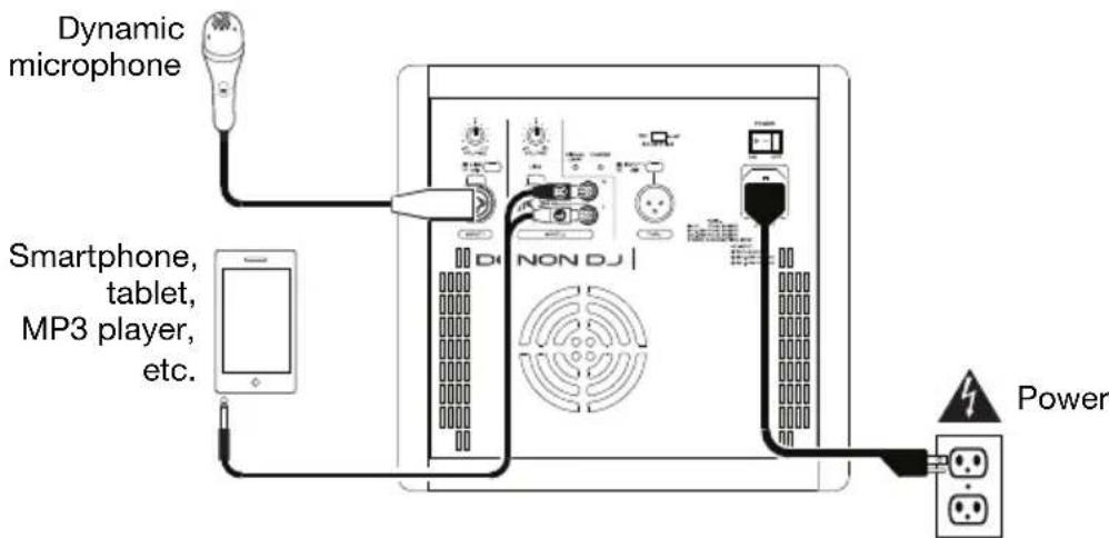
Connect a dynamic microphone to Input 1 using an XLR or 1/4'' (6.35 mm) TRS cable. Make sure the Line/Mic Selector is set to Mic. Connect a media player (smartphone, tablet, MP3 player, etc.) to Input 2's RCA connectors using a 1/8'' -to-RCA (3.5mm-to-RCA) cable.
Note: Use only dynamic microphones with the loudspeaker unless you are also using an external phantom power supply.
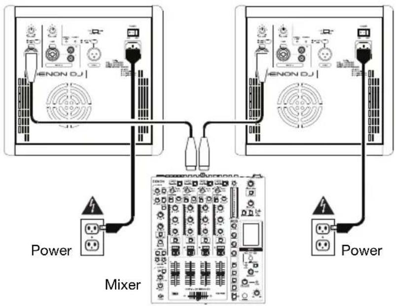
Example 2: 2 loudspeakers with mixer
Connect the left and right output of your mixer to Input 1 of each loudspeaker using XLR or 1/4 (6.35 mm) TRS cables. Make sure the Line/Mic Selectors are set to Line.
Tip: To send the same mix to both loudspeakers, connect both channels of your mixer to the Inputs 1 and 2 of one loudspeaker, set its Input 1/Mix Selector to Mix, and then connect that loudspeaker's Thru Output to Input 1 of the other loudspeaker. Both loudspeakers will then play identical summed mono mixes.
Tip: To add extension loudspeakers in a "daisy chain" configuration, connect the Thru Output to the input of your additional loudspeaker. Be sure to set the Input 1/Mix Selector to the desired setting.
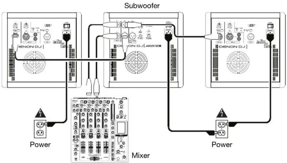
Example 3: 1 subwoofer and 2 loudspeakers with mixer
Using XLR or 1/4" (6.35 mm) TRS cables, connect the left and right output of your mixer to the inputs of your subwoofer, and then connect each high-pass output of the subwoofer to Input 1 of each loudspeaker. Make sure the Line/Mic Selectors are set to Line.
Important Safety Precautions
Please note: Denon DJ and inMusic are not responsible for the use of its products or the misuse of this information for any purpose. Denon DJ and inMusic are not responsible for the misuse of its products caused by avoiding compliance with inspection and maintenance procedures. Please also refer to the included safety and warranty manual for more information.
Stand-Mounting
Always install loudspeakers in accordance with applicable electrical and building codes.
- Install the loudspeaker according to its maximum weight. Check the specifications of your stand or pole to ensure it can support the loudspeaker's weight. Also, observe all safety precautions specified by the manufacturer.
- Do not mount multiple loudspeakers on the same stand or pole.
- Always verify that the stand or pole is on a flat, level, and stable surface. Also, fully extend the legs of tripod-style stands, and ensure its legs do not present a trip hazard.
- Inspect the stand (or pole and associated hardware) before each use and do not use equipment with worn, damaged, or missing parts.
- Always be cautious in windy, outdoor conditions. You may need to place additional weight (e.g., sandbags) on stand's base to improve stability. Do not attach banners or similar items to any part of a loudspeaker system. Such attachments could act as a sail and topple the system.
Unless you are confident that you can handle the loudspeaker's weight, ask another person to help you lift it onto the stand or pole.
- Make sure your cables are out of the way of performers, production crew, and audience so they will not trip over them, pulling the loudspeaker off the stand or pole.
Sound Level
Permanent hearing loss may be caused by exposure to extremely high noise levels. The U.S. Occupational Safety and Health Administration (OSHA) has specified permissible exposures to certain noise levels. According to OSHA, exposure to high sound pressure levels (SPL) in excess of these limits may result in hearing loss. When using equipment capable of generating high SPL, use hearing protection while such equipment is under operation.
| Hours per day | SPL (dB) | Example |
| 8 | 90 | Small gig |
| 6 | 92 | Train train |
| 4 | 95 | Subway |
| 3 | 97 High level desktop monitors | music |
| 2 | 100 | Classical machine |
| 1.5 | 102 | Riveting factory |
| 1 | 105 | Machine |
| 0.50 | 110 | Airport |
| 0.25 or less 115 | Rock concert |
Features
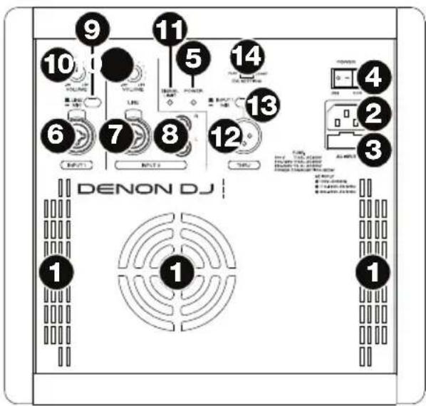
Rear Panel
-
Cooling Vent: Keep the area in front of this vent clear from obstructions. The fan behind the vent cools the amplifier, preventing overheating. This fan operates as needed to control the amplifier's internal temperature. Due to minor differences in electrical component tolerances, it is normal for the fan speed and behavior to vary from unit to unit. This variance does not affect the unit's performance.
-
Power Input: Connect the included power cable to this input and connect the other end of the cable to a power source. Make sure the Power Switch is set to off when plugging and unplugging the cable.
-
Fuse: If the unit's fuse is broken, lift this tab to replace the fuse. Replace it with a fuse with an appropriate rating (printed under the unit's power cable input). Using a fuse with an incorrect rating can damage the unit and/or fuse.
-
Power Switch: Turns the loudspeaker on/off. Make sure the Input Volume knobs are set to "zero" before turning it on.
-
Power LED: Illuminates when the loudspeaker is on.
-
Input 1: Use a standard XLR or 1/4 (6.35 mm) TRS cable (not included) to connect a sound source to this input, and set the Line/Mic Selector appropriately.
-
Input 2 (XLR or 1/4'' TRS): Use a standard XLR or 1/4'' (6.35 mm) TRS cable (not included) to connect a sound source to this input. The signal sent here will be mixed with the signal sent to this input's RCA connectors.
-
Input 2 (RCA): Use a standard RCA cable to connect a sound source to this input. The signal sent here will be mixed with the signal sent to this input's XLR + 1 / 4 (6.35 mm) connector.
-
Line/Mic Selector: Set this switch to the Line position when using a line-level audio source connected to Input 1. Set this switch to the Mic position when using a microphone connected to Input 1.
-
Input Volume: Turn this knob to adjust the input volume of the channel.
-
Signal/Limit LED: This LED lights up green when an audio signal is sent to the loudspeaker—it flashes at lower levels and lights solidly at higher levels. The LED lights up red when output limit/protection is active—if the LED is lit red continuously, reduce the volume of your audio source.
-
Thru Output: Use a standard XLR cable (not included) to connect this output to the input of another loudspeaker. The signal sent out of this output depends on the setting of the Input 1/Mix Selector.
-
Input 1/Mix Selector: Press this switch to determine the audio signal sent out of the Thru Output:
Input 1 (raised): The Input 1 signal is sent out of Thru Output, post-Input Volume.
- Mix (depressed): The summed mono mix of both Inputs is sent out of the Thru Output, post-Input Volume.
-
EQ Setting: Set this switch to determine the loudspeaker's equalization:
-
Flat: The levels of the frequencies of the output signal will be the same as those of the input signal. We recommend this setting if you intend to make EQ adjustments on an external mixer.
- Boost: The low and high frequencies will be boosted slightly while mid-range frequencies are reduced slightly. We recommend this setting for lower listening levels.
this is a long, simple, and easy to understand text. It is a very useful tool for the preparation of projects that require the use of a specific equipment. This is a great way to prepare projects that require the use of a specific equipment.
Assistance technique
Technical Specifications
Any differences between Axis 8 and Axis 12 are noted below.
Specifications are subject to change without notice.
| Power System | 2000 W peak, 1000 W continuous Class D; 500 W LF + 500 W HF with DSP |
| Frequency Response | 45 Hz - 20 KHz (Axis 12) 55 Hz - 20 KHz (Axis 8) |
| Maximum SPL | 128 dB (from driver sensitivity and amp power) (Axis 12) 125 dB (from driver sensitivity and amp power) (Axis 8) |
| Coverage | 90° conical |
| Transducer Low | 12" (304mm) woofer, 2.5" (64mm) voice coil (Axis 12) 8" (203mm) woofer, 2" (51mm) voice coil (Axis 8) |
| Transducer High | 1" (25mm) exit compression Celestion driver 1.75" (44mm) voice coil |
| Active Crossover | at 1.85 KHz with 24 dB filter slope |
| Connections | Input 1: XLR+1/4" (6.35mm) TRS combination input with line/mic selector Input 2: XLR+1/4" (6.35mm) TRS combination input or 1 RCA stereo input pair Thru Output: XLR Power: IEC power cable input |
| Input Level | Line 0 dBu |
| External Controls | Volume control, power switch with LED, signal/clip limiter with LED |
| Digital EQ Presets | Flat, Boost |
| Electronic Protections | Thermal, convection fan, overload, digital limiter, compressor |
| Enclosure | Trapezoidal plywood cabinet, top and bottom high-strength ABS, black paint, metal grille |
| Mounting | 1 standard 36mm pole mount; 1 plastic handle |
| Power | Connection: Standard IEC cable Input Voltage: 110-120, 220-240 V AC; 50/60 Hz Inrush Current: 10.09 A Consumption: 800 W Fuse: 110-120 V: T10AL AC250V or 220-240 V: T5AL AC250V |
| Dimensions (width x depth x height) | 15.3" x 14.4" x 16.3" / 38.8 cm x 36.5 cm x 41.4 cm (Axis 12) 14.0" x 12.5" x 13.4" / 35.6 cm x 31.7 cm x 34.0 cm (Axis 8) |
| Weight | 36.5 lbs. / 16.6 kg (Axis 12) 29.0 lbs. / 13.1 kg (Axis 8) |
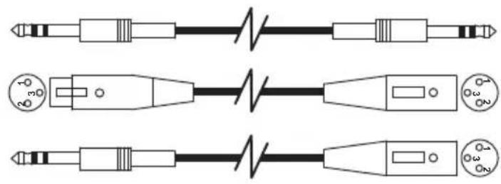
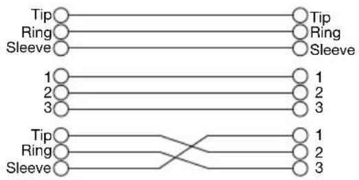
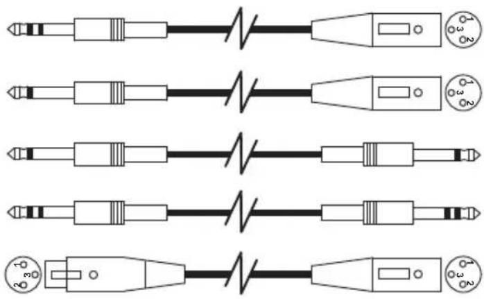
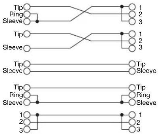
Wiring Diagrams
Trademarks and Licenses
Denon is a trademark of D&M Holdings Inc., registered in the U.S. and other countries.
All other product or company names are trademarks or registered trademarks of their respective owners.
denondj.com