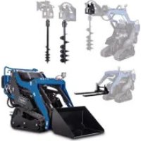
MKL730 - Construction Equipment SCHEPPACH - Free user manual and instructions
Find the device manual for free MKL730 SCHEPPACH in PDF.


| Product type | Compact tracked loader |
| Brand | Scheppach |
| Model | MKL730 |
| Category | Construction machine |
| Operating weight | Approx. 749 kg |
| Unladen weight | Approx. 715 kg |
| Mobile payload | 200 kg (according to ISO 14397-1) |
| Track width | 740 mm |
| Max. lift height | Approx. 2000 mm |
| Engine type | 4-stroke engine, air cooling |
| Engine rated power | 6.3 kW (8.5 hp) |
| Max. engine speed | 3600 min⁻¹ |
| Displacement | 306 cm³ |
| Fuel | Super gasoline E5/E10 |
| Fuel tank volume | 6.0 liters |
| Engine oil tank volume | 1.1 liters |
| Hydraulic system | Pump capacity 2×15 l/min, pressure 175 bar |
| Hydraulic oil tank volume | 29 liters (HLP 32) |
| Drive type | Rubber tracks |
| Travel speed | 0-2.3 km/h (forward/reverse) |
| Power supply | 12 V battery |
| Guaranteed sound power level | 101 dB |
| Included accessories | 80-liter earth bucket, wrenches, funnel, charger |
| Greasing interval | Every 4 operating hours |
| Warranty | Legal warranty, original parts recommended |
Frequently Asked Questions - MKL730 SCHEPPACH
User questions about MKL730 SCHEPPACH
0 question about this device. Answer the ones you know or ask your own.
Ask a new question about this device
Download the instructions for your Construction Equipment in PDF format for free! Find your manual MKL730 - SCHEPPACH and take your electronic device back in hand. On this page are published all the documents necessary for the use of your device. MKL730 by SCHEPPACH.
USER MANUAL MKL730 SCHEPPACH
- 2x Gabelschlüssel/Steckschlüssel SW 13 mm*
Division Manager Product Center

Head of Project Management
Garantiebedingungen
Revisionsdatum 26.11.2021
1 Introduction 46
2 Product description (Fig. 1-35) 46
3 Scope of delivery (Fig. 1-35) 46
4 Proper use 47
5 Safety instructions 47
6 Technical data 52
7 Unpacking. 53
8Assembly 54
9 Before commissioning 54
10 Operation 56
11 Working instructions 59
12 Cleaning and maintenance 59
13 Storage 65
14 Transport 65
15 Repair and ordering spare parts 66
16 Disposal and recycling. 66
17 Troubleshooting 67
18 EU Declaration of Conformity 68
19 Exploded view 233
Explanation of the symbols on the product
Symbols are used in this manual to draw your attention to potential hazards. The safety symbols and the accompanying explanations must be fully understood. The warnings themselves will not rectify a hazard and cannot replace proper accident prevention measures.
| Before commissioning, read and observe the operating manual and safety instructions! | |
| Attention! Failure to observe the safety signs and warning information affixed to the product and failure to observe the safety and operating manual can result in serious injury or even death. | |
| Before commissioning, read and observe the operating manual and safety instructions! | |
| Wear safety goggles. | |
| Wear hearing protection. | |
| Always wear a safety helmet! | |
| Protective and safety devices must not be removed or manipulated. | |
| Keep a safe distance from moving parts. | |
| Do not start the engine by short-circuiting the starter terminals. | |
| Never start the engine in enclosed spaces. | |
| Smoking, sparking and open fires are prohibited. | |
| Keep the device away from water and do not expose it to rain. | |
| Important. The exhaust gases are toxic. Do not operate the engine in areas that are not ventilated. | |
| Danger of explosion. Never use a preheater and do not touch any earth supply lines. | |
| Attention flammable substances. Fire, naked flames and smoking prohibited. | |
| Do not touch any parts that are hot from operation - risk of severe burns. | |
| Do not connect the positive and negative terminals of the battery incorrectly. Overheating or improper use may result in an explosion. | |
| Attention! Flying objects can cause injury. | |
| Keep your hands away from this area. | |
| Pressurised liquids or air can penetrate the skin and cause serious injury or even death. Keep a sufficient distance. | |
| Be careful of horizontal movements. There is a risk of serious or even fatal crushing injuries. | |
| Beware of falling objects. There is a danger of crushing. Keep away from raised loads/components and their range of movement. | |
| Risk of cutting and crushing the foot: Before performing maintenance work, ensure that all moving parts have come to a standstill. Keep away from moving parts or tools and always keep protective devices in place. | |
| Danger of cutting and crushing: Before maintenance work, ensure that all moving parts have been stopped. Keep away from moving parts or tool attachments and always keep protective devices in place. | |
| Danger of cutting and crushing: Before maintenance work, ensure that all moving parts have been stopped. Keep away from moving parts or tool attachments and always keep protective devices in place. | |
| Make sure that other persons maintain a sufficient safety distance. | |
| Keep a sufficient distance from the tool attachment and the lifting arm. | |
| Keep a sufficient distance from the tool attachment and the lifting arm. | |
| Fill the oil before commissioning! An oil monitor prevents the engine starting when there is insufficient oil. | |
| Maintenance or repair only when the engine is switched off and after reading the instructions. | |
| Do not overload the product. | |
| Keep your hands away from rotating parts. | |
| Risk of electric shock. Before using the product, check whether there are any power lines nearby. | |
| Attention! The exhaust pipe and other parts of the product become very hot during operation, do not touch! | |
| During operation, only the operator is allowed to be on the product. The presence of other persons is not permitted. | |
| During operation, the operator must remain on the operating platform. | |
| Avoid sudden starts, braking or turning – there is an increased risk of falling, especially on uneven ground! | |
| Before leaving the product, lower the tool attachment to the ground, switch off the engine and remove the ignition key. | |
| Do not leave the operating platform while a load is being lifted. | |
| There is a risk of tipping. Always keep loads in a low position. | |
| There is an increased risk of tipping when driving on slopes or inclines. | |
| Before reversing, always ensure that there are no children, people or obstacles in the danger zone by looking over your shoulder. | |
| Always drive uphill and downhill with the tool attachment lowered; keep the heavier end uphill. There is a risk of tipping. | |
| Never lift loads while driving. Always keep loads in a low position. | |
| Keep away from break-off edges – the weight of the product may cause the ground to give way, resulting in a fall or tipping. This can result in serious or fatal injury. Do not dig under the product or tool attachment. Be careful when filling. | |
| Risk of electric shock: Avoid contact between the tool attachment or the lifting arm and overhead power lines or other obstacles. | |
| Steep slopes and high embankments can slide. Avoid working under overhangs and do not undermine them. Watch out for falling rocks and slippery surfaces. | |
| The maximum load capacity is 200 kg. This load capacity must not be exceeded under any circumstances. | |
| The maximum loading height is 2.0 m. | |
| Lifting point | |
| Transport anchoring. | |
| Lubrication points. | |
| Tank contents | |
| Top up hydraulic oil. | |
| Horn. | |
| Battery disconnect switch | |
| - + 101 dB | Battery/load. |
| LwA | Guaranteed sound power level of the product. |
| CHARGE | Operating display. Position on the operating platform. |
| LED headlights. Position on the operating platform. | |
| Horn. Position on operating platform. | |
| Opening/closing the engine cover. Position on operating platform. | |
| Storage location for operating manual. Position on the operating platform. Note: All operating manuals must always be attached to the product. | |
| Storage location for operating manual. Position under the engine cover. | |
| Sight glass for hydraulic oil level. Positioned centrally on the hydraulic tank. | |
| Sight glass for hydraulic oil level. Position at the bottom of the hydraulic tank. | |
| CE | The product complies with the applicable European directives. |
| ΔΔΔ | The product complies with the applicable Serbian directives. |
Brief explanation - Maintenance item
Secure lifting arms in maintenance position
Lifted loads pose a risk of serious or fatal crushing injuries.
| 1.2. | OFF | Position the holes in the lifting arms so that they align with the maintenance position holes in the base frame. Exit the operating platform. Turn the ignition key to “OFF” and take it off. Set the fuel tap to “OFF”. Secure the lifting arms with the locking pins (20x120 mm) and fix them with the corresponding split pins. Read the operating manual and wear personal protective equipment (PPE). |
| 3.4. |
Brief explanation - Removing the tool attachment
Remove tool attachment
| Lower the tool attachment to the base. | |
| Exit the operating platform. Turn the ignition key to "OFF" and take it off. Set the fuel tap to "OFF". | |
| Disconnect the hydraulic lines. | |
| Remove the split pins and pull the bolts out upwards. | |
| Start the engine. Lift the tool holder upwards. Tilt the tool holder and move the product away from the tool holder. |
1 Introduction
Manufacturer:
Scheppach GmbH
GünzburgerstraBe 69
D-89335 Ichenhausen
Dear Customer
We hope your new product brings you much enjoyment and success.
Note:
In accordance with the applicable product liability laws, the manufacturer of this product assumes no liability for damage to the product or caused by the product arising from:
- Improper handling
Non-compliance with the operating manual - Repairs carried out by third parties, unauthorised specialists
- Installing and replacing non-original spare parts
- Improper use
Note:
The operating manual is part of this product.
It includes important instructions for the safe, proper and economic operation of the product, for avoiding danger, for minimising repair costs and downtimes and for increasing the reliability and extending the service life of the product. In addition to the safety instructions in this operating manual, you must also observe the regulations applicable to the operation of the product in your country.
Familiarise yourself with all operating and safety instructions before using the product. Only operate the product as described and for the specified areas of application. Keep the operating manual in a good place and hand over all documents when passing the product on to third parties.
2 Product description (Fig. 1-35)
- Hydraulic lines
1a. Quick coupling
1b. Plug nipple - Engine cover
2a.Key - Holder
3a. Holes
3b. Support pad
3c.Screws (M8x25mm)
3d. Washers (M8)
3e. Snap ring (M8)
3f. Nut (M8) - Base frame
4a. Lifting points
4b. Elongated holes
4c. Maintenance position holes - Operating platform
5a. Safety pedal -
Rubber crawler chassis
6a. Rubber crawler
6b. Screw (M12x30 mm)
6c. Counternut (I)
6d. Adjusting nut (M12)
6e. Counternut (M12)
6f. Screw (M12x80 mm)
6g. Drive wheel
6h. Follower roller -
Tool attachment holder
7a. Shaft (top)
7b. Shaft (bottom)
7c. Bolt (20× 80mm)
- Lifting arm
8a. Hole
8b. Locking pin (20x120 mm)
- Battery compartment
9a. Safety key
9b.Lock
9c. Screw
9d. Battery
-
LED headlights
-
Operating station
11a. Left operating lever
11b. Right operating lever
11c. Hydraulic control lever
11d. Replacement hydraulic control lever
- Control panel
12a. Operating display
12b. Button (LED headlight)
12c. Button (horn)
- E-start
13a. Ignition lock
13b. Ignition key
13c. Overload switch
14.Pull starter
-
Throttle
-
Fuel valve
-
Choke
-
Transport frame
18a.Screw (M8)
- Engine oil tank
19a. Oil dipstick
19b. Oil drain hose
- Fuel tank
20a. Fuel filler cap
20b. Fuel filter insert
20c. Funnel
- Earth bucket
21a. Mounting bracket
21b. Recess
- Air filter cover
22a. Fixing nut
22b. Wing nut
22c. Air filter
- Spark plug connector
23a. Spark plug
-
Horn
-
Hydraulic oil tank
25a. Sight glass (top)
25b. Sight glass (bottom)
25c. Fuel filler cap
25d. Seal
25e. Union nut
25f. Suction filter
-
Grease nipple
-
Installation spanner
3 Scope of delivery (Fig. 1-35)
Item Quantity Designation
2a. 1x Key
3. 2 x Mounting brackets (with support pads)
3c. 10x Screws (M8x25 mm)
3d. 20 x Washers (M8)
3e. 10x Snap ring (M8)
3f. 10 x Nut (M8)
7c. 2 × Bolt (20x80 mm)
8b. 4 × Locking pin (20x120 mm)
9a. 1 x Safety key
13b. 2 x Ignition key
20c. 1 x Funnel
- 1 x Earth bucket (80 litres)*
Article no.: 7915400705
27.1 x Installation spanner
1 x Skid steer loader
1 x Operating manual
^* = may not be included in the scope of delivery!
4 Proper use
The skid steer loader may only be used without tool attachments fitted for the following purposes:
Driving and manoeuvring within the intended area of application (e.g. construction sites, company premises, paved areas).
Positioning or moving the product, e.g. for maintenance, cleaning or to switch tool attachments.
Use for lifting, moving or editing material is not permitted without a suitable tool attachment.
If faults occur during operation that could compromise safety, switch off the skid steer loader immediately. In this case, it may only be put back into operation once the cause has been rectified and full operational safety has been restored.
The product may only be used in the intended manner. Any use beyond this is improper. The user, not the manufacturer, is responsible for damages or injuries of any type resulting from this.
An element of the intended use is also the observance of the safety instructions, as well as the assembly instructions and operating information in the operating manual.
Persons who operate and maintain the product must be familiar with the manual and must be informed about potential dangers.
The liability of the manufacturer and resulting damages are excluded in the event of modifications of the product.
The product may only be operated with original parts and original accessories from the manufacturer.
The safety, operating and maintenance specifications of the manufacturer, as well as the dimensions specified in the technical data, must be observed.
Please note that our products were not designed with the intention of use for commercial or industrial purposes. We assume no guarantee if the product is used in commercial or industrial applications, or for equivalent work.
4.1 Improper use
Do not make any changes to the product. Safety may be compromised as a result. The user, not the manufacturer, is responsible for damages or injuries of any type resulting from this.
People who are not familiar with the operating manual, people under the influence of alcohol, drugs or medication, and people who are tired or unwell are not allowed to operate the product.
National regulations may restrict the use of the product!
The following activities are expressly prohibited:
- Lifting and transporting people.
-
Use of the product as an aerial work platform.
-
Lifting and transporting loads, unless the tool attachments are designed for this purpose.
- Towing trailer loads.
- Use of the product after improper troubleshooting or repair.
- Driving on public roads and traffic routes.
Explanation of the signal words in the operating manual

DANGER
Signal word to indicate an imminently hazardous situation which, if not avoided, will result in death or serious injury.

WARNING
Signal word to indicate a potentially hazardous situation which, if not avoided, could result in death or serious injury.

CAUTION
Signal word to indicate a potentially hazardous situation which, if not avoided, could result in minor or moderate injury.
ATTENTION
Signal word to indicate a potentially hazardous situation which, if not avoided, could result in product or property damage.
5 Safety instructions
ATTENTION
Attention!
When using products, several safety warnings must be observed to prevent injuries and damage. For this reason, please carefully read this operating manual/safety instructions. If you hand the product over to another person, please hand over this operating manual/safety instructions as well. We accept no liability for accidents or damage that occur due to a failure to observe this manual and the safety instructions.
Follow the safety instructions
Keep all safety information and instructions for future reference!
5.1 Familiarising yourself with the product
- Read the entire operating manual before using the product.
-
Observe the warning and information signs attached to the product. They provide important notes for safe operation.
Familiarise yourself with the controls and the proper use of the product. -
It must be ensured that the product is only operated by trained persons who have read and understood the enclosed operating manual and observe all instructions and safety precautions contained therein.
5.2 Working range
- Before using the product or attaching a tool attachment, carefully check the surrounding area. The product is not suitable for use under harsh conditions, such as extreme air-conditioning packages or hazardous environments, where special safety measures are required.
- The product must not be used in contaminated environments.
- Do not work with the product in an explosive environment.
- Keep children and other people away while using the product. Distractions may cause you to lose control of the product.
5.3 Personal safety
- Do not use the product while tired or under the influence of drugs, alcohol or medication. Do not use products if you are tired.
- Wear suitable clothing! Do not wear wide clothing or jewellery, which can become entangled in moving parts or tool attachments. It is recommended to wear sturdy gloves, non-slip shoes, hearing protection and safety goggles.
- During operation, only the operator is allowed to be on the product. The presence of other persons is not permitted.
- Keep hands and feet away from the rotating parts and tool attachments.
5.4 Operation and care
- Check the product, in particular the protective devices and mechanical components, for damage such as loose, worn or damaged parts before each use. Check all nuts, pins and screws for firm seating.
- For safety reasons, replace worn or damaged parts.
- Before starting up, ensure that the product is in good condition, filled with fuel, properly lubricated and greased, and that all maintenance work has been carried out.
- The product must not be modified. Modifications can reduce the effectiveness of the safety measures and increase risks for the operator.
- Check the covers and protective devices for damage and correct seating. Replace them if necessary.
- If the protective structure is impaired by plastic deformation and/or cracks – for example, as a result of being run over, tipped over or struck by an object – it must be replaced in accordance with the manufacturer's specifications.
5.5 Safety instructions when children are present
Not paying attention to children around you can have serious and tragic consequences. Children often show great interest in products, but do not recognise the dangers associated with them and often behave unpredictably.
-
Never assume that children will remain where you last saw them.
-
Always keep children under the supervision of a responsible adult and away from the work area.
- Always be attentive and stop the product immediately if children enter the work area.
- Never allow children to ride on the product.
There is no safe place for them. Children may fall off, be run over or obstruct the operator while the product is in use.
- Never allow children to operate the product. Never allow adults who have not been trained to operate the product.
Children must not play with the product or the tool attachment. - Before reversing, always ensure that there are no children, people or obstacles in the danger zone by looking over your shoulder.
- Place the product on a level, even surface. Before leaving the product, lower the tool attachment to the ground, switch off the engine, take off the ignition key and wedge the rubber track chassis.
5.6 Special safety instructions
5.6.1 Before use
Check the area thoroughly to select a suitable tool attachment and the appropriate accessories for the job at hand. So that you can carry out your work properly and safely.
Only use tool attachments and accessory parts approved by the manufacturer.
The use of other insertion tools and other accessories can entail a danger of injury.
- Prepare your workstation properly. Do not work near buildings or objects that could be damaged by the product. Remove debris or loosely attached materials that could move unexpectedly when driving over them and cause a hazard.
- Keep people away from raised lifting arms, tool attachments and unsupported loads. Use barriers or signal generators to warn vehicles and pedestrians. Honk the horn before starting the product to alert bystanders.
- Avoid contact between the lifting arm or tool attachment and overhead power lines and other obstacles. Watch out for hidden holes, obstacles, soft ground and overhangs to avoid hazards.
- Avoid contact with gas pipes, underground cables and water pipes when working with certain tool attachments.

DANGER
There may be underground supply lines in the work area.
Damage to these lines may result in electric shock or explosion.
Have the site checked for underground cables and only dig in marked areas.
Contact your local service provider or utility company to have the area marked!
- Keep the product clean. Heavy soiling, grease, dust and grass can ignite and cause accidents or injuries.
5.6.2 Safe operation
- Ensure that all drives are in neutral before starting the engine. Only start the engine from the operating platform.
- Never start up the product if protective devices are missing or not securely fitted. Ensure that all locking mechanisms are correctly fitted, properly set and fully functional.
- Never exceed the rated operating load. The product may become unstable and control may be lost.
- Never lift loads while driving. Always keep loads in a low position.
- Always secure tool attachments securely, even for short sections, and store accessories neatly.
5.6.2.1 Working on slopes

DANGER
Slopes increase the risk of losing control and tipping over, which can result in serious injury or fatal accidents. Be particularly careful when using the product on slopes and uneven terrain.
Observe the following information to reduce hazards:
- Take into account the inclination of the product in all axes.
Maximum lateral inclination: 11^
Maximum inclination: 25^ - Always drive uphill and downhill with the load lowered. Adjust your driving accordingly to ensure the stability of the product. Make sure to hold the heavier end of the product on the hanging side.
The weight distribution varies depending on the tool attachment:
- When the bucket is empty, the rear end is heavier.
- When the bucket is full, the weight is at the front.
-
With tools such as the clamshell bucket or dozer blade, the centre of gravity is also at the front.
-
When driving on slopes, raised lifting arms reduce the stability of the product.
Always keep loads in a low position.
- When the tool attachment is uncoupled on a slope, the weight shifts to the rear, making the rear heavier.
- Drive and move the product slowly and in a controlled manner on slopes.
Avoid sudden changes in direction or speed. - Avoid starting and stopping on slopes. If traction is lost, drive slowly and straight down the slope.
- Avoid turning on slopes. If necessary, turn slowly and keep the heavy end facing upwards.
- Do not park the product on slopes or embankments without lowering the tool attachment to the ground and wedging the rubber crawler chassis.
5.6.2.2 Safety instructions for the rubber crawler chassis
The rubber crawler chassis allows for versatile movement. To prevent premature wear of the rubber crawlers, the following points must be observed.
-
Driving or turning on sharp-edged objects or steps puts a lot of strain on the rubber crawler and can cause breaks or notches in the tread.
-
Make sure that there are no foreign objects in the rubber crawlers, as these are subject to heavy loads during operation and foreign objects can cause damage or tears.
- Avoid getting fuel or oil on the rubber crawlers. If this happens, clean the affected area immediately.
- Sharp turns on tracks with high friction coefficients, such as concrete or asphalt surfaces, can place heavy loads on the rubber crawlers.
- Avoid working near fall edges, trenches or embankments. The rubber crawler chassis can tip over suddenly if a rubber crawler runs over an edge or breaks through it.
- Avoid working on wet grass, as reduced traction can cause the product to slip.
- Always pay attention to the direction in which the product is moving and check the path for possible obstacles.
- Get in and out safely. Please use the handrails for this purpose. Do not jump on or off the product.
5.6.3 Work complete
- Place the product on a level, even surface.
- Lower the tool attachment completely to the ground.
- Switch off the auxiliary hydraulics.
- Switch off the engine and remove the ignition key from the ignition lock.
- Pull the safety key out.
5.6.4 Fire protection
The product has components that are exposed to high temperatures during operation, especially the engine and the exhaust system. In addition, damaged or poorly maintained electrical equipment can generate sparks or arcs, which pose a fire hazard.
Observe the following information to reduce hazards:
- When working under difficult conditions, deposits near hot engine exhaust parts should be blown out regularly. All combustible materials such as leaves, straw and wood chips must be removed from the trough, the underbody and the area around the engine to prevent fire hazards.
- Regularly check all fuel lines and hydraulic lines for wear and damage. If there are any signs of leaks, they must be replaced immediately.
- Check electrical lines and plug connectors regularly for damage. Have any damage rectified immediately and only by an electrician.
- Check the exhaust system daily for leaks, broken pipes and silencers, and for screws, nuts and clamps that are loose or missing. If leaks or damaged parts are found, repairs must be completed before use to ensure safe operation.
- Always keep a multi-purpose fire extinguisher near the product or directly on it. Operating personnel must be trained in the use of the fire extinguisher and know how to use it quickly and correctly in an emergency.
5.6.5 Hydraulic hazards
If hydraulic oil gets into your eyes, rinse them immediately with plenty of clean water and seek medical attention immediately.
- Avoid contact of skin and clothing with hydraulic oil. If hydraulic oil comes into contact with the skin, wash the affected areas thoroughly with soap and water immediately to prevent skin irritation and dermatosis. If hydraulic oil gets on your clothing, change it immediately.
- If hydraulic oil vapours are inhaled, seek medical attention immediately. If a leak occurs in the hydraulic system, do not start the product or stop it immediately.
- Oil leaks must not be checked with bare hands. Wear personal protective equipment. Wearing personal protective equipment such as work clothes, safety goggles and gloves reduces the risk of injury.

WARNING
Danger of burning!
The temperature of the hydraulic oil rises during operation, which can lead to a risk of burns.
5.6.6 Emergency measures
5.6.6.1 Electric shock
Special precautionary measures are required when working near power lines.
Observe the following information to reduce hazards:
- Current does not spread exclusively via the path of least resistance to earth.
- Current can flow back into products via pipes, hoses and cables.
- Low voltage can cause serious, sometimes fatal injuries. Numerous work-related electrical accidents result from contact with voltages below 440 volts.
Most electric shocks are not felt immediately, but there are typical signs that may indicate an electric shock:
Power failure
Smoke is produced
- Explosion
- Loud bangs
- Arc formation
If one or more of these symptoms occur, an electric shock is likely.
5.6.6.2 Damage to a power line
If you suspect that a power line is damaged, do not move.
Observe the following information to reduce hazards:
- Once you are on the product, stay there. Lift the tool attachment and move the product out of the immediate danger zone.
- When you are not on the product, do not touch the product or the tool attachment.
- Leave the work area with small steps and keep your feet close together. This reduces the risk of electric shock from so-called step voltage.
- Immediately inform any persons standing nearby about the electric shock and instruct them to leave the danger zone immediately.
- Contact the power supply company immediately to have the power supply disconnected.
- The work area may only be re-entered with the permission of the power supply company after it has been vacated. No unauthorised access.
5.6.6.3 Damage to a gas pipe
Observe the following information to reduce hazards:
- The engine must be switched off immediately if this can be done safely and without delay.
- Remove all sources of ignition immediately, provided this can be done safely and without delay.
- Immediately inform any bystanders that a gas pipe has been cut and instruct them to leave the danger zone immediately.
- Leave the danger zone immediately.
- Contact the utility company immediately.
- If the work area is located on a road, traffic in the affected area must be stopped immediately.
- The work area may only be re-entered with the permission of the emergency services and the utility company. No unauthorised access.
5.6.6.4 Damage to a fibre optic cable
Do not look into cut ends of fibre optic cables or unidentified cables, as this may cause damage to your eyesight.
Contact the utility company immediately.
5.6.6.5 Fire involving the product
Perform an emergency shutdown immediately.
Observe the following information to reduce hazards:
- Remove the battery safety key (if accessible).
- Attempt to extinguish the fire if it is small and a fire extinguisher is available.
- If the fire cannot be extinguished, leave the work area immediately and notify the emergency services.
5.6.7 Loading and unloading products safely

WARNING
Loading and unloading a product onto a trailer or lorry increases the risk of tipping.
This can result in serious or fatal injury.
- Extreme caution is required when driving onto or off a ramp.
with lowered tool attachment. - When loading the product via a ramp, only reverse gear may be used. The heavier side of the product must always be facing uphill to prevent tipping or slipping. When unloading the product, it is permissible to drive forwards.
-
Avoid sudden starts and stops, as this can lead to loss of control and cause the product to tip over.
-
Observe all regulations on public roads when transporting the product.
- When loading the product onto a lorry, use ramps that are sufficiently long and stable.
- Only use ramps that are suitable for the weight of the product.
- To prevent tipping, do not change the direction of travel.
After loading, switch off the engine, remove the safety key and remove the spark plug connector from the spark plug. -
Use suitable wedges to secure the rubber crawler chassis against uncontrolled movements.
-
Only use fasteners that are suitable for the weight of the product.
Observe local regulations for fastening.
5.6.8 Lifting the product safely
The product can also be lifted onto a trailer/lorry using suitable lifting devices.

WARNING
Lifting work must only be carried out by qualified personnel with appropriate training and instruction.

DANGER
Danger to life!
Persons must never be in the movement area of raised loads.
Lifted loads pose a risk of serious or fatal crushing injuries.

WARNING
Danger of crushing!
Pay attention to your fingers!
Observe the following information to reduce hazards:
- Remove the tool attachment.
- Only use the lifting points provided and marked by the manufacturer.
- Only use slinging gear and lifting devices that are suitable for the weight of the product.
- Only lift the product at the four lifting points.
- When lifting the product, ensure that the angle of inclination does not exceed 20 degrees.
5.7 Handling fuel
ATTENTION
Use only E5 or E10 unleaded petrol as fuel.

DANGER
Danger to life!
Fuel is toxic and highly flammable.
- Only store fuel in containers (canisters) designed for this purpose.
- The tank caps must always be properly screwed on and tightened.
- For safety reasons, the fuel tanks and other fuel caps must be replaced if damaged.
- Keep fuel away from sparks, open flames, permanent flames, heat sources and other sources of ignition. Do not smoke!
- Refuel outdoors only and do not smoke while refuelling.
-
Before refuelling, switch off the combustion engine and let it cool down.
-
Fuel must be filled before starting the engine. While the engine is running or immediately after switching off the product, do not open the fuel filler cap or add fuel.
- Open the fuel cap carefully and slowly. Wait for the pressure to equalise and only then remove the fuel filler cap completely.
- Use a suitable funnel or filler pipe for refuelling so that no fuel can spill onto the combustion engine and housing. Do not overfill the fuel tank!
- To leave room for the fuel to expand, never fill the fuel tank beyond the lower edge of the filling nozzle. Observe additional information in the combustion engine user manual.
- If fuel has overflowed, do not start the combustion engine until the area contaminated with fuel has been cleaned. Avoid starting the engine until the fuel vapours have evaporated (wipe dry).
- Always wipe up spilled fuel immediately.
- If fuel has got on clothing, it must be changed.
- The tank cover must be properly screwed on and tightened after each refuelling operation. The product must not be put into operation without the original tank cover screwed on.
- For safety reasons, check fuel line, fuel tank, fuel cap and connections regularly for damage, ageing (brittleness), tight fit and leaks and replace if necessary.
- Only empty the tank outdoors.
- Never use beverage bottles or similar to dispose of or store operating materials, such as fuel. People, especially children, could be tempted to drink from it.
- Never store the product with fuel in the tank inside a building. Any fuel vapours produced can come into contact with naked flames or sparks and ignite.
- Do not place the product and fuel tank near heaters, radiant heaters, welding machines or other sources of heat.

DANGER
Risk of explosion!
If a defect is detected on the tank, the tank cover or on fuel-carrying parts (fuel lines) during operation, the combustion engine must be switched off immediately.
Then consult a specialist dealer.
5.8 Battery safety
- To avoid spark formation due to a short circuit, always disconnect the negative cable (-) from the battery first and reconnect it last.
- Never smoke during work on the battery. Always keep sparks, naked flames and other heat sources away from the battery.
- Special care must be taken when using jumper cables. Follow relevant instructions to avoid damage to the device (in particular, do not operate the starter for more than 10 seconds).
- Never open the battery and do not drop it.
- Always charge the battery in a closed room with good ventilation, dry and protected against the weather.
-
Do not short-circuit battery connections.
-
Deformed or defective (leaking) batteries must not be used and must be replaced and disposed of in an environmentally friendly manner. Observe the country-specific regulations.
- If the batteries are defective, liquid may leak out. Avoid contact! In case of accidental contact, rinse with water. If the liquid gets into your eyes, seek additional medical attention. Leaking battery fluid can cause skin irritation, burns and chemical burns.
- Regularly visually inspect the connection cables on the battery for damage. Have damaged cables replaced by a specialist.
- Never bypass the fuses. Never use a fuse with a rating other than the prescribed rating (amperes).
5.8.1 Safety instructions for handling batteries
- Always make sure that the batteries are inserted with the correct polarity (+ and -), as indicated on the battery.
- Do not short-circuit batteries.
- Do not charge non-rechargeable batteries.
- Do not overcharge batteries!
- Do not mix old and new batteries or batteries of different types or manufacturers! Replace an entire set of batteries at the same time.
- Immediately remove used batteries from the device and dispose of them properly! Do not throw batteries away with household waste. Defective or used batteries must be recycled in accordance with Directive 2006/66/EC. Return batteries and / or the device via the collection facilities provided. You can find out about disposal options from your local or municipal authority.
- Do not allow batteries to heat up!
- Do not weld or solder directly on batteries!
- Do not disassemble the batteries!
- Do not allow batteries to deform!
- Do not throw batteries into fire!
- Keep batteries out of the reach of children.
- Do not allow children to replace batteries without supervision!
- Do not store batteries near fire, ovens or other sources of heat. Do not use batteries in direct sunlight or store them in vehicles in hot weather.
- Keep unused batteries in the original packaging and keep them away from metal objects. Do not mix unpacked batteries or toss them together!
This can lead to a short circuit of the battery and thus damage, burns or even the risk of fire.
- Remove batteries from the product when it will not be used for an extended period of time, unless it is for emergencies!
- NEVER handle batteries that have leaked without appropriate protection. If the leaked fluid comes into contact with your skin, the skin in this area should be rinsed off under running water immediately. Always prevent the fluid from coming into contact with the eyes and mouth. In the event of contact, please seek immediate medical attention.
- Clean the battery contacts and corresponding contacts in the device prior to inserting the batteries.
Residual risks
The product has been built according to state-of-the-art and the recognised technical safety rules. However, individual residual risks can arise during operation.
- Furthermore, despite all precautions having been met, some non-obvious residual risks may still remain.
- Residual risks can be minimised if the "Safety Instructions" and the "Intended Use" together with the operating manual as a whole are observed.
- Prevent the product being unintentionally started up.
- Keep your hands away from the working area when the product is in operation.
- Unintentional starting up of the product.
- Comply with the stipulated maintenance and safety instructions in the operating manual.

WARNING
In case of extended working periods, the operating personnel may suffer circulatory disturbances in their hands (vibration white finger) due to vibrations.
Raynaud's syndrome is a vascular disease that causes the small blood vessels on the fingers and toes to cramp in spasms. The affected areas are no longer supplied with sufficient blood and therefore appear extremely pale. The frequent use of vibrating products can cause nerve damage in people whose circulation is impaired (e.g. smokers, diabetics).
If you notice unusual adverse effects, stop working immediately and seek medical advice.
6 Technical data
| General: | |
| Operating weight approx. 749 kg | |
| Empty weight approx. 715 kg | |
| Max. tipping load* approx. 425 kg | |
| Mobile payload | 200 kg |
| (Per ISO 14397-1) | |
| Track width 740 mm | |
| Crawler width 180 mm | |
| Lifting height approx. 2000 mm | |
| Max. lateral inclination | 11° |
| Max. incline | 25° |
| Ground clearance | 114 mm (centre), 62 mm (side) |
| Ground pressure | 32 kPa |
| Travel speed (F/R) | 0-2.3 km/h |
| Lifting arm | 6.6 seconds/4.4 seconds |
| lifting/lowering time | |
| Engine: | |
| Type of engine | 4-stroke engine, air-cooled |
| Rated engine power | 6.3 kW (8.5 PS) |
| Max. engine speed | 3600 rpm |
| Displacement 306 cm | 3 |
Torque 18.5 Nm
Start system Electric starter (12 V)
Fuel E10 and E5
CO_2 output 788.2 g/kWh
Fuel tank volume 6.0 litres
Engine oil tank volume 1.1 litres
Hydraulic system:
Pump capacity 2 × 15 ~l / min
System pressure 175 bar
Hydraulic oil tank capacity 29 I (HLP 32)
Accessories included in scope of delivery:
Earth bucket 735× 675× 385mm (80 l) (7915400705)
*detained without driver, without dynamic effects, on level, solid ground, with earth bucket 7915400705
Subject to technical changes!
Noise and vibration

WARNING
Noise can have serious effects on your health. If the machine noise exceeds 85 dB, please wear suitable hearing protection for you and persons in the vicinity.

WARNING
Please observe the legal provisions from the noise protection ordinance.
Information on the noise emissions of the product has been determined in accordance with the requirements of EN ISO 4871:2009 and based on Directive 2000/14/EC, Annex VI:
Noise data
| Sound pressure level LpA | 77.9 dB |
| Measurement uncertainty KpA | 3 dB |
| Sound power level LwA | 97.9 dB |
| Guaranteed sound power level LwA | 101 dB |
| Measurement uncertainty KwA | 2.85 dB |

WARNING
The noise emission values and vibration emission value can vary from the specified values during the actual use of the product, depending on the type and the manner in which the product is used, and in particular the type of workpiece being processed.
Try to keep the stress as low as possible. For example: Limit working time. In doing so, all parts of the operating cycle must be taken into account (such as times in which the product is switched off or times in which it is switched on, but is not running under a load).
If necessary, adhere to rest periods and limit the duration of work to the bare minimum.
Information on vibration development measured in accordance with the relevant standards (EN 12096:1997):
Vibration parameters (hand/arm vibration)
| Vibration a_eq | 0.4 m/s2 |
| Vibration a HV | 2.38 m/s2 |
Keep the noise level and vibration to a minimum!
Observe the following information to reduce hazards:
- Only use faultless products.
- Maintain and clean the product at regular intervals.
- Adapt your working methods to the product.
- Do not overload the product.
- Have the product checked if necessary.
- Switch the product off if it is not in use.
- Wear gloves.
- Keep your body and especially your hands warm in cold weather.
- Take regular breaks and move your hands to promote circulation.
- Ensure as little vibration as possible of the product via regular maintenance and stable parts on the product.
7 Unpacking

WARNING
The product and the packaging material are not children's toys!
Do not let children play with plastic bags, films or small parts! There is a danger of choking or suffocating!
- Remove the packaging material, as well as the packaging and transport safety devices (if present).
- Check whether the scope of delivery is complete.
- Check the product and accessory parts for transport damage. Immediately report any damage to the transport company that delivered the Product. Later claims will not be recognised.
- Familiarise yourself with the product by means of the operating manual before using for the first time.
- With accessories as well as wearing parts and replacement parts use only original parts. Spare parts can be obtained from your specialist dealer.
- When ordering please provide our article number as well as type and year of manufacture for the product.
Tool required:
- 2x open-ended spanner/socket spanner, size 13mm^*
Utility knife* - Suitable slinging gear*
- Suitable lifting device*
^* = may not be included in the scope of delivery!
7.1 Removing the transport frame (18) (Fig. 3)
- Remove the packaging material. Use a utility knife. Pay attention to your fingers!
- Remove the screws (18a) from the transport frame (18).
- Carefully remove the transport frame (18).
- Cut and remove the straps securing the product.
7.2 Lifting the product (Fig. 3)
Observe the safety instructions as described under 5.6.8.

DANGER
Danger to life!
Persons must never be in the movement area of raised loads.
Lifted loads pose a risk of serious or fatal crushing injuries.

WARNING
To avoid injury, the product must only be lifted without any tool attachments fitted.

WARNING
The lifting points are marked with appropriate symbols. Lifting at other points is unsafe and may result in personal injury or damage to the product.
Notes:
The product must only be lifted without using tool attachments.
Before lifting, make sure that the lifting device (crane or hoist) is capable of carrying the product weight without danger. See type plate for weight of lifting device.
Observe the instructions of the slinging gear and lifting device manufacturer.
Only use approved lifting devices (min. lifting capacity 1000 kg).
- Attach the slinging gear to the designated lifting points (4a).
- Hook the slinging gear into the lifting device.
- Lift the product a small distance and make sure that all slinging gear is properly fastened.
- You can now lift the product as desired using the lifting device.
- Place the product on a level, even surface.
8 Assembly
ATTENTION
Always carry out assembly and adjustments on the product with the engine switched off and disconnect the spark plug connector.
- Do not fit any products or accessories to the product that are not provided by or approved by the manufacturer.
Tool required:
- 2x open-ended spanner/socket spanner, size 13mm^
^ = may not be included in the scope of delivery!
8.1 Fitting the holders (3) (Fig. 4)
- Place a mounting bracket (3) on the base frame (4).
Make sure that the holes (3a) in the mounting brackets (3) line up with the elongated holes (4b) in the base frame (4). - Insert one M8x25 mm screw (3c) with washer (3d) through the corresponding holes and secure it with a washer (3d), a snap ring (3e) and a nut (3f).
- Adjust the mounting brackets (3) individually to suit your body size by using the adjustment option provided by the elongated holes (4b).
- Tighten all nuts (3f) and screws M8x25 mm (3c). Use two open-ended wrenches/socket wrenches size 13 mm.
Notes:
- The support pads (3b) are pre-mounted on the mounting brackets (3).
- Before starting up, check that the mounting brackets (3) are correctly positioned and that the screw connections are tight.
9 Before commissioning

WARNING
For your own safety, please thoroughly read this manual and the general safety instructions before turning the product on. If you give the product to third parties, always include these operating instructions.
ATTENTION
Always make sure the product is fully assembled before commissioning!
ATTENTION
At initial start-up, engine oil and fuel must be filled.
Note:
The product is delivered with hydraulic oil already filled.
ATTENTION
Product damage!
If the product is operated without oil or with too little oil or with used oil, this can lead to product damage.
- Fill with oil before starting the machine. The product is delivered without oil.
- Do not use used oil!
- Check the oil level before each operation.
ATTENTION
Environmental damage!
Spilled oil can pollute the environment permanently. The liquid is highly toxic and can quickly lead to water pollution.
-
Fill/empty oil only on level, paved surfaces.
-
Use a filling nozzle or funnel.
- Collect drained oil in a suitable container.
- Wipe up spilled oil carefully immediately and dispose of the cloth according to local regulations.
- Dispose of oil as per local regulations.

DANGER
Danger to life!
Fuel is toxic and highly flammable.

DANGER
Risk of fire and explosion!
Only fill the fuel when the engine is switched off and has cooled down. Do not smoke when refuelling the product.

DANGER
Risk of fire and explosion!
When filling, fuel may ignite and even explode. This can lead to severe burns or death.

WARNING
Health hazard!
Inhalation of fuel / lubricating oil vapours and exhaust gases can cause serious damage to health, unconsciousness and in extreme cases death.
- Do not breathe fuel / lubricating oil vapours and exhaust gases.
- Empty out fuel only outdoors.
Note:
Place the product on a level, even surface.
Tool required:
Funnel (20c)
-Funnel
Rag/cloth
^* = may not be included in the scope of delivery!
9.1 Filling up with engine oil (Fig. 5)
ATTENTION
The product is delivered without engine oil. Therefore, ensure that you add oil before starting it up. Use SAE 10W-40 or SAE 15W-40 oil for this.
The engine oil affects the performance and service life of the product.
Use an engine oil for 4-stroke engines.
Make sure that the oil meets the API SERVICE classification SJ or higher - you will find this information on the oil container label.
Check the oil level regularly before commissioning. An oil level that is too low can damage the motor.
- Unscrew the oil dipstick (19a).
- Fill the engine oil tank (19) using a funnel. Do not exceed the maximum filling level (see Technical Data). Carefully fill the engine oil to the lower edge of the filling nozzle.
- Wipe the oil dipstick (19a) with a clean, lint-free cloth.
- Reinsert the oil dipstick (19a) without screwing the oil dipstick (19a) back on.
- Pull the oil dipstick (19a) out and read the oil level in the horizontal position. The oil level must be between L (low) and H (high) on the oil dipstick (19a).
- If the oil level is too low, add the recommended amount of engine oil (see Technical Data).
- Then screw the oil dipstick (19a) in again.
9.2 Opening/closing the engine cover (2) (Fig. 6)
Opening:
- Unlock the engine cover (2) by turning the key (2a) anticlockwise.
- Lift the engine cover (2) and open it completely.
Closing:
- Close the engine cover (2).
- Lock the engine cover (2) by turning the key (2a) clockwise.
9.3 Filling in fuel (Fig. 6)
- Switch off the engine and let it cool down.
- Keep heat, flames and sparks away.
- Only fill up with fuel outdoors.
- Wear protective gloves.
- Avoid contact with skin and eyes.
- Avoid using old or contaminated fuel and do not use fuel-oil mixtures.
- Make sure that no dirt or water gets into the fuel tank.
Note:
Check the fuel level every time before commissioning.
ATTENTION
The product is delivered without fuel. It is therefore essential to fill with fuel before commissioning. Use Super E5/E10 petrol for this.
- Open the engine cover (2) as described in 9.2.
- Clean the tank cover (20a) and the area around the filling nozzle to prevent dirt or foreign objects from entering the fuel tank (20).
-
Carefully open the tank cover (20a) so that any possible overpressure can be relieved. The fuel filler cap (20a) is connected to an anti-loss device in the fuel tank (20) and thus cannot fall off.
-
Remove the fuel filter insert (20b).
- Check the fuel level by visual inspection.
- Reinsert the fuel filter insert (20b).
- Fill the fuel tank (20) with fuel using a funnel (20c). Note the max. filling capacity of 6.0 litres. Carefully fill the fuel up to the lower edge of the filling port.
- Seal the tank cover (20a) again by placing it straight on and turning it clockwise. Make sure that the tank cover (20a) is completely sealed to prevent leaks and evaporation.
- Clean the tank cover (20a) and the surroundings.
- Check the fuel tank (20) and fuel lines for leaks.
- Close the engine cover (2).
9.4 Connecting/disconnecting a battery (9d) (Fig. 7)
The enclosed safety key (9a) can be used to close or interrupt the battery circuit (9d).

WARNING
Disconnect the battery and always take off the safety key before making any settings on the product.
To connect the battery:
- Insert the safety key (9a) into the lock (9b).
- Turn the safety key (9a) clockwise until it audibly clicks into place. The product is now ready for use.
To disconnect the battery:
- Turn the safety key (9a) anti-clockwise; the battery (9d) is now disconnected.
- Take off the safety key (9a).
10 Operation
10.1 Safety pedal (5a) (Fig. 8)
In an emergency, leave the operating platform (5) immediately.
The safety pedal (5a) is equipped with a spring-loaded safety switch located below the safety pedal (5a). This safety switch automatically interrupts the power supply to the engine as soon as the operator leaves the operating platform (5). For safety reasons, the product may only be operated when the operator is standing on the operating platform (5).
10.2 Overload switch (13c) (Fig. 9)
The motor is equipped with an overload switch (13c). If the product is overloaded, the overload switch (13c) switches off automatically to protect the product from overheating.
- If the overload switch (13c) has been triggered, switch off the product as described under 10.5.3 and wait until the product has cooled down.
- Now press the overload switch (13c) and switch the product on again.
10.3 Explanation of the control panel (12) (Fig. 9)
Insert the ignition key (13b) into the ignition lock (13a) and turn it to the "ON" position.
Operating display (12a):
The LED of the operating display (12a) lights up green continuously as soon as the ignition key (13b) is turned to the "ON" position and the battery circuit (9d) is closed as described under 9.4.
Button (LED headlight) (12b):
Pressing the button (12b) switches the LED headlight (10) on or off.
Button (horn) (12c):
Pressing the button (12c) causes the horn (24) to sound.
10.4 Explanation of the controller (Fig. 10, 19, 20, 23)
Left operating lever (11a):
- Forward/reverse (in combination with right operating lever).
- Drive left/right.
- Swivel the tool attachment upwards or downwards.
Right operating lever (11b):
- Forward/reverse (in combination with left operating lever).
- Drive left/right.
- Raise or lower the lifting arms.
Hydraulic control lever (11c):
- Open or close the grippers or clamshell bucket.
- Tilt the dozer blade* to the left or right.
- Turn the earth auger* clockwise or anti-clockwise.
Replacement hydraulic control lever (11d):
- No function.
For further information on how to use the product, please refer to the additional descriptions (see 10.5, 10.6 und 10.8).
10.5 Switching the product on/off (Fig. 11-18)

DANGER
Danger of poisoning!
Only use the product outdoors and never in closed or poorly ventilated rooms.
NOTE
If the engine is being started for the first time, several tries are required to start until the fuel has been delivered from the tank to the engine.

WARNING
Risk of fire and explosion!
Never use pre-glow or starter fluid! This can lead to severe burns or death.
WARNING
In an emergency, leave the operating platform immediately.
When leaving the operating platform, a safety switch under the safety pedal automatically switches off the product.
The product is equipped with a pull starter (14) and an electric starter (13).
Before starting:
- Read the entire operating manual before using the product.
- Familiarise yourself with the product by means of the operating manual before using for the first time.
- During operation, the operator must remain on the operating platform.
- Honk the horn before starting the product to alert bystanders.
- Check the fuel and engine oil levels before each start (see 9.3 and 9.1).
- Make sure that the spark plug connector (23) is attached to the spark plug (23a).
- Remove the battery (9d) as described in 9.4.
- If the battery is flat, the product can be started using the pull starter.
After starting:
- Allow the engine to warm up briefly.
- Allow the hydraulic fluid to warm up sufficiently before starting operation at cold outside temperatures, as cold fluid can significantly delay the response time of the product.
- Use the throttle to set the required speed (15).
MIN position, "tortoise"
-MAX position, "hare"
10.5.1 Using the pull starter (14) to start the engine (Fig. 11-16)
ATTENTION
- Always pull the pull starter out straight.
- Hold the handle of the pull starter firmly when the pull starter winds back in.
- Do not let the pull starter whip back in. This can result in damage.
- Do not pull the pull starter all the way out. This prevents the starter cable breaking.
- In case of cool weather, it may be necessary to repeat the starting process numerous times.
10.5.1.1 Starting a cold engine
Note:
With high outside temperatures, it may be necessary to start the engine without the choke even when the engine is cold!
- Set the fuel valve (16) to "ON".
- Set the choke (17) to the "CHoke" position.
- Position the throttle (15) in the middle.
-
Insert the ignition key (13b) into the ignition lock (13a).
-
Turn the ignition key (13b) to the "ON" position.
- Now pull the pull starter (14) slowly several times so that fuel can flow from the fuel tank (20) to the engine.
- Start the engine by pulling the pull starter (14) quickly. If the engine does not start, repeat the process.
- Let the engine warm up for several seconds.
- Turn the choke (17) to the "RUN" position slowly.
- Use the throttle to set the required speed (15).
10.5.1.2 Starting a warm engine
(The product stood still for less than 15-20 minutes.)
- Set the fuel valve (16) to "ON".
- The choke (17) must be in the "RUN" position.
- Position the throttle (15) in the middle.
- Insert the ignition key (13b) into the ignition lock (13a).
- Turn the ignition key (13b) to the "ON" position.
- Start the engine by pulling the pull starter (13a) quickly. If the engine does not start, repeat the process.
- Use the throttle to set the required speed (15).
- If the engine does not start even after several attempts, start the product as described in section 10.5.1.1.
10.5.2 Using the electric starter (13) to start the engine (Fig. 11-15, 17)
10.5.2.1 Starting a cold engine
- Set the fuel valve (16) to "ON".
- Set the choke (17) to the "CHoke" position.
- Position the throttle (15) in the middle.
- Insert the ignition key (13b) into the ignition lock (13a).
- Turn the ignition key (13b) to the "START" position and hold it in this position until the product starts up.
- Let the engine warm up for several seconds.
- Turn the choke (17) to the "RUN" position slowly.
- Use the throttle to set the required speed (15).
- If the engine does not start even after several attempts, start the product as described in section 10.5.1.1.
10.5.2.2 Starting a warm engine
- Set the fuel valve (16) to "ON".
- The choke (17) must be in the "RUN" position.
- Position the throttle (15) in the middle.
- Insert the ignition key (13b) into the ignition lock (13a).
- Turn the ignition key (13b) to the "START" position and hold it in this position until the product starts up.
- Use the throttle to set the required speed (15).
- If the engine does not start even after several attempts, start the product as described in section 10.5.1.1.
10.5.3 Switching off the engine (Fig. 1, 18, 26)
Note:
After switching off the product, wait two minutes before interrupting the battery circuit.
- Place the product on a level, even surface.
- Lower the tool attachment* completely to the ground.
-
Stop all product movements.
-
Set all operating levers (11a, 11b, 11c) to neutral position.
- Leave the operating platform (5) and turn the ignition key (13b) to the "OFF" position.
- Remove the ignition key (13b) when leaving the product.
- Set the fuel valve (16) to "OFF".
- During maintenance or prolonged storage, take off the spark plug connector (23) from the spark plug (23a) and interrupt the battery circuit (9d) as described in 9.4.
- Allow the engine to cool down before parking the product in enclosed spaces.
10.6 Operating the travel drive (Fig. 19, 20)
ATTENTION
When moving the product, lift the lifting arms or tool attachment slightly, but keep it low.
Note:
The product may run out on a slope because the fuel in the tank flows forward and the fuel supply is interrupted.
The direction of travel of the individual rubber crawlers (6a) is controlled via the adjustment levers (11a/11b).
Driving forward:
- Press both operating levers (11a/11b) forward at the same time.
Driving in reverse:
- Pull both operating levers (11a/11b) back simultaneously.
Changing direction:
-
Push the right operating lever (11b) forward.
-
The right rubber crawler moves forward, causing the product to turn to the left.
-
Pull the right operating lever (11b) backwards.
-
The right rubber crawler moves backwards, causing the product to turn to the right.
-
Press the left operating lever (11a) forward.
-
The left rubber crawler moves forward, causing the product to turn to the right.
-
Pull the left operating lever (11a) backwards.
-
The left rubber crawler moves backwards, causing the product to turn to the left.
Driving curves and radii:

WARNING
Warning about spot turns (turning on the spot)!
Spot turns at high speeds can lead to rocking, instability and accidents.
Only perform spot turns at low speed.
- Curves and radii can be driven by pressing and pulling the operating levers (11a/11b) with varying degrees of force.
- The greater the difference in the operating lever movement between the left and right rubber crawlers (6a), the tighter the turning radius.
Note:
Only operate one operating lever to change the direction of travel when the product is stationary or moving.
To turn the product on the spot, push one operating lever forward and the other backward at the same time.
10.7 Attach/remove the tool attachment (Fig. 21, 22)
Attach the tool attachment:
- Place the tool attachment on a level, even surface.
Make sure there is enough space behind the tool attachment. - Start the engine as described in 10.5, to move the product, as described in 10.6, to the tool attachment.
- Lower the lifting arm (8) and tilt the tool attachment (7) downwards until the upper shaft (7a) engages in the mounting bracket (21a) of the tool attachment.
- Tilt the tool attachment holder (7) backwards to engage the tool attachment.
- Lift the lifting arm (8) so that the lower shaft (7b) of the tool attachment holder (7) engages in the recess (21b) of the tool attachment.
- Secure the tool attachment by inserting a bolt (7c) through each of the drill holes in the recess (21b) and securing it with split pins.
- Lower the lifting arm (8) to place the tool attachment on the ground.
- Check that the tool attachment is correctly inserted and secured.
- Remove the tool attachment in reverse order.
Note:
Scan the QR code below to access the operating manuals for the various tool attachments.

10.7.1 Connecting hydraulic lines (1) (Fig. 22)
Connect the hydraulic lines if the tool attachment requires hydraulic power for operation.

WARNING
Pressurised liquids or air can penetrate the skin and cause serious injury or even death.
To avoid injury:
- Keep a sufficient distance.
- Oil leaks must not be checked with bare hands. Wear personal protective equipment.
Before disconnecting the hydraulic lines, switch off the engine and take off the safety key. Operate all operating levers to completely relieve the system pressure.
- Lower raised components, secure them or support them with suitable aids.
- Release the residual pressure in the hydraulic tank.
Before starting up, check that all connections are secure and that all lines are undamaged.
- In case of injury, seek medical attention immediately.
ATTENTION
Hot surfaces! Risk of burns on contact. Only handle when cool or wear suitable protective gloves.
- Relieve any residual pressure as described in 12.2.6.2.
- Clean all quick couplings and plug nipples of dirt, dust and deposits to prevent contamination of the hydraulic system.
- Connect the quick coupling of the tool attachment to the plug nipple (1b) of the hydraulic lines (1).
- Connect the plug nipple of the tool attachment to the quick coupling (1a) of the hydraulic lines (1).
- Before starting up, check that the hydraulic connections are secure.
10.8 Operating the tool attachment (Fig. 23)
Select a suitable tool attachment for the work to be performed.
To operate the lifting arm (8):
Move the right operating lever (11b) to the left or right to raise or lower the lifting arm (8).
To operate the tool attachment:
Move the left operating lever (11a) to the left or right to swivel the tool attachment down or up.
To operate hydraulic functions of the tool attachment:
Move the hydraulic control lever (11c) to the left or right to control the appropriate tool attachment.
- Open/close bucket or gripper.
- Tilt the snow blade* to the left/right.
- Turn the earth auger clockwise or anti-clockwise.
^ = may not be included in the scope of delivery!
11 Working instructions
11.1 Reducing rubber track wear (Fig. 1)
Rubber crawlers (6) are particularly suitable for use on soft, unpaved ground with few stones or debris.
To minimise wear on the rubber crawlers (6), always drive at reduced speed and with a large turning circle.
To avoid the following stresses:
- Spinning of the rubber crawlers under heavy loads.
- Turning on sharp surfaces (e.g. stones, broken concrete, rubble).
- Tight turning manoeuvres on solid surfaces such as asphalt or concrete.
- Driving over high kerbs, edges or protrusions.
- Driving up to or grinding the rubber crawlers on walls or kerbs.
- Working on aggressive surfaces (e.g. salt, fertiliser or other aggressive substances)
12 Cleaning and maintenance

WARNING
Have maintenance and repair tasks that are not described in this operating manual, carried out by a specialist workshop. Use only original spare parts.

WARNING
Improper maintenance or cleaning work can cause injuries!

WARNING
The product may start unexpectedly and cause injuries and burns during cleaning, repair and maintenance work.
- Switch the product off.
- Turn the ignition key to the "OFF" position.
- Remove the ignition key.
- Remove the safety key.
- Remove the spark plug connector from the spark plug.
- Allow the product to cool.

WARNING
Carry out a visual and functional check/maintenance regularly/daily and before commissioning to ensure that the product is in good operating condition.
- Incorrect maintenance, use of non-conforming replacement parts, or removal or modification of safety equipment may lead to severe property or personal damages.
- If this work cannot be carried out by the user themselves, see a specialist dealer.
12.1 Cleaning
- Keep protective devices, air vents and the motor housing as free of dust and dirt as possible. Rub the product clean with a clean cloth or blow it off with compressed air at low pressure. We recommend that you clean the product directly after every use.
- To reduce the risk of fire, regularly clean the cooling fins of the engine with compressed air. Clear the silencer area of dust, leaves or other foreign objects.
- Ventilation openings must always be free.
- Clean the product at regular intervals using a damp cloth* and a little soft soap. Do not use any cleaning products or solvents; they could attack the plastic parts of the product. Make sure that no water can penetrate the product interior.
- Cleaning and user maintenance must not be carried out by children.
- Only carry out cleaning and maintenance work to the extent specified in this operating manual. Further work must be carried out by qualified specialists.
12.1.1 Cleaning the fuel filter insert (20b) (Fig. 6)
Note:
The petrol filter is a fuel filter insert cup, which is located directly under the fuel cap and filters all the fuel that is filled in.
- Open the engine cover (2) as described in 9.2.
- Open the tank cover (20a) by turning it anti-clockwise. The fuel filler cap (20a) is connected to an anti-loss device in the fuel tank (20) and thus cannot fall off.
- Remove the fuel filter insert (20b). Clean it in a non-flammable solvent or a solvent with a high flash point.
- Reinsert the fuel filter insert (20b).
- Seal the tank cover (20a) again by placing it straight on and turning it clockwise. Make sure that the tank cover (20a) is completely sealed to prevent leaks and evaporation.
- Close the engine cover (2).
12.2 Maintenance
Observe the safety instructions as described under 5.
Place the product on a level, even surface.
Any work not described in this operating manual must be performed by an authorised specialist workshop only.
Maintain the product carefully. Check for misalignment or binding of moving parts, breakage of parts and any other condition that may affect the product's operation. Have damaged parts repaired before using the product.
Regular, careful servicing is required to guarantee the safety level and performance of the product.
Remove all tools used for maintenance before operating or storing the product.
All protective and safety equipment must be reassembled immediately after repair and maintenance work is completed.
To avoid the risk of fire, hydraulic components such as tanks, lines, hoses or cylinders must only be heated once they have been completely emptied and thoroughly cleaned.
Tool required:
- Locking pin (20x120 mm) (8b)
Funnel (20c) - Installation spanner
Copper wire brush* - Feeler gauge
Rag/cloth*
Collection bucket
Funnel* - Open-ended spanner/socket spanner, size 10mm^*
- 2x open-ended spanner, size 13mm^*
- 2x open-ended spanner, size 19mm^
- Socket spanner, size 19 mm*
- Phillips screwdriver*
- Battery charger*
- Oil extraction pump*
Grease gun*
^* = may not be included in the scope of delivery!
12.2.1 Secure the lifting arms (8) in the maintenance position (Fig. 24)
In order to be able to carry out maintenance work in the area below the lifting arms (8) safely even in the event of pressure loss, it is necessary to secure the lifting arms (8) properly.
Proceed as follows:
- If necessary, remove the tool attachment as described in 10.7.
- Position the lifting arms (8) so that the holes (8a) in the lifting arms (8) line up with the maintenance position holes (4a) in the base frame (4).
- Switch off the engine as described in 10.5.3 and remove the safety key (9a).
- Secure the lifting arms (8) with the locking pins (8b) and fix them with the corresponding split pins.
- Check that the locking pins (8b) are secure on both sides.

WARNING
Be sure to remove the locking pins after completing the work.
12.2.2 Maintenance plan
Always comply with the following maintenance intervals in order to ensure problem-free operation.
Attention! At initial start-up, engine oil and fuel must be filled.
| Operating hours Before com- | missioning | 10 hours 5 | hours 200 | hours 1000 hours | 2 years | 6 years | |
| General visual inspection | x | ||||||
| Check the fuel level | x | ||||||
| Check the fuel line x | |||||||
| Change fuel lines X | |||||||
| Checking the engine oil level x | |||||||
| Change the engine oil x | |||||||
| Check hydraulic lines x | |||||||
| Change hydraulic lines X | |||||||
| Check hydraulic oil level x | |||||||
| Switch hydraulic oil x | |||||||
| Switch hydraulic suction filter insert x | |||||||
| Check lubrication points, lubricate if necessary | x | ||||||
| Clean product x | |||||||
| Check electrical lines x | |||||||
| Check battery status x | |||||||
| Check the air filter x | |||||||
| Clean the air filter x | |||||||
| Replace air filter x | |||||||
| Check and clean the spark plug if necessary | x | ||||||
| Replace the spark plug x | |||||||
| Rubber track settings | Initial check | x | |||||
| Attention: Only have points “X” carried out by an authorised specialist company. | |||||||
12.2.3 Maintaining the air filter (22c) (Fig. 25)
ATTENTION
Risk of damage!
Operating the engine without a filter element or with a damaged filter element can cause engine damage.
- Never run the engine without the air filter element or with a damaged filter element. This would allow dirt into the engine, which would result in severe damage to the engine.
ATTENTION
Fouled air filters diminish the engine output due to reduced air supply to the carburettor. Regular inspection is therefore essential.
ATTENTION
If the product is used in a particularly dusty environment, the air filter must be checked and cleaned more frequently than specified in the regular maintenance intervals.
ATTENTION
Do not clean the product with the engine running. Water could penetrate the air filter and damage the engine.
Keep the air filter dry.
ATTENTION
Never clean the air filter with petrol or combustible solvents.
Clean the air filter (25c) every 50 operating hours; it is recommended to
replace the air filter (25c) after 200 operating hours.
- Open the engine cover (2) as described in 9.2.
- Remove the air filter cover (22) by disassembling the fastening nut (22a).
- Loosen the wing nut (22b) by turning it anti-clockwise and remove the air filter (22c).
- Only clean the air filter (22c) by knocking it out.
- Replace a faulty air filter (22c) with a new one.
- Reinsert the air filter (22c) and secure it by tightening the wing nut (22c) clockwise.
- Fit the air filter cover (22) and secure it with the fixing nut (22a).
- Close the engine cover (2).
12.2.4 Maintaining the spark plug (23a) (Fig. 25-27)
ATTENTION
Only replace the spark plug when the engine is cold!
ATTENTION
A loose spark plug can overheat and cause damage to the engine. Tightening the spark plug too much can damage the thread in the cylinder head.
Electrode gap = 0.6mm (distance between the electrodes, between which the ignition spark is generated). Check the spark plug for dirt for the first time after 10 operating hours and clean it with a copper wire brush if necessary. Then service the spark plug every 50 operating hours.
Replace the spark plug (23a) after 500 operating hours or after one year at the latest.
- Move the lifting arms (8) to the maintenance position as described in 12.2.1.
- Open the engine cover (2) as described in 9.2.
- Remove the air filter cover (22) by disassembling the fastening nut (22a).
- Remove the spark plug connector (23) and disassemble the spark plug (23a). Use an installation spanner (27).
- Remove any dirt from the base of the spark plug (23a).
- Clean the spark plug (23a) with a copper wire brush or replace it with a new one.
- Check the spark plug gap. Use a feeler gauge to adjust the electrode gap to 0.6 - 0.7mm
- Replace the spark plug (23a) and take care not to tighten it excessively.
- Then place the spark plug connector (23) on the spark plug (23a).
- Fit the air filter cover (22) and secure it with the fixing nut (22a).
- Close the engine cover (2).
12.2.5 Maintaining fuel lines and hoses
- Before each start-up, check that all fuel lines, hoses and hose clamps are securely fastened and undamaged.
- Replace fuel lines, hoses and hose clamps when worn or damaged, or every two years.
12.2.6 Maintaining the hydraulics (Fig. 28)
ATTENTION
Product damage!
If the product is operated without oil or with too little oil or with used oil, this can lead to product damage.
- Do not use used oil!
- Check the oil level before each start-up.
ATTENTION
Environmental damage!
Spilled oil can pollute the environment permanently. The liquid is highly toxic and can quickly lead to water pollution.
- Fill/empty oil only on level, paved surfaces.
- Use a filling nozzle or funnel.
- Collect drained oil in a suitable container.
- Wipe up spilled oil carefully immediately and dispose of the cloth according to local regulations.
- Dispose of oil as per local regulations.
The product is delivered already filled with ISO 32 hydraulic oil.
The following oil types are recommended:
10W AW32
ASLE H-150
ISO 32
- Move the lifting arms to the maintenance position as described in 12.2.1.
- Before working on the hydraulic tank (25), release the residual pressure as described in 12.2.6.2.
12.2.6.1 Checking the oil level (Fig. 28)
- Lower the tool attachment completely to the ground.
- Check the oil level at an ambient temperature of approx. 10 to 30^ using the sight glasses (25a/25b).
Upper sight glass (25a):
Half full.
- The hydraulic stand is adequate.
- Empty.
- Check the fill level of the lower sight glass (25b).
Upper sight glass (25b):
Full.
- There is sufficient hydraulic oil. The hydraulic stand should be monitored.
Half full.
- The hydraulic oil must be refilled as described in 12.2.6.3 before restarting the engine to protect the hydraulic system from damage.
12.2.6.2 Relieving the hydraulic oil tank (25) (Fig. 28)
- Cover the union nut (25e) with a heavy cloth.
- Loosen the union nut (25e) to release the remaining pressure in a controlled manner.
Use a size 19 mm open-ended spanner.
12.2.6.3 Topping up the hydraulic oil (Fig. 28)
- Disassemble all screws, snap rings and washers on the tank cover (25c) of the hydraulic oil tank (25). Use a size 10mm open-ended spanner / socket spanner.
- Remove the tank cover (25c) and the seal (25d).
- Fill hydraulic oil into the filler opening using a funnel.
- Fit the tank cover (25c) of the hydraulic oil tank (25) again.
Make sure that you fit the seal (25d) correctly
- Check the oil level through the sight glasses (25a/25b) after a short period of operation. The oil level should be in the middle of the sight glas (25a).
- If the oil level is too low, repeat the process.
12.2.6.4 Changing the hydraulic oil (Fig. 28)
Frequent changing of tool attachments can cause more foreign objects to enter the hydraulic system through the lines, which may make it necessary to change the suction filters (25f) more often. Proceed as described in 12.2.6.5.
- Disassemble all screws, snap rings and washers on the tank cover (25c) of the hydraulic oil tank (25). Use a size 10 mm open-ended spanner / socket spanner.
- Remove the tank cover (25c) and the seal (25d).
- Remove the hydraulic oil using an oil extraction pump.
- Fill approx. 29 litres of fresh hydraulic oil into the filler opening (see technical data).
- Fit the tank cover (25c) of the hydraulic oil tank (25) again.
Make sure that you fit the seal (25d) correctly. - Dispose of the used oil properly.
12.2.6.5 Changing the suction filter (25f) (Fig. 28)
Frequent changing of the tool attachment can cause more foreign objects to enter the hydraulic system through the lines, making it necessary to change the suction filter (25f) more often.
- Disassemble all screws, snap rings and washers on the tank cover (25c) of the hydraulic oil tank (25). Use a size 10mm open-ended spanner / socket spanner.
- Remove the tank cover (25c) and the seal (25d).
- Remove the hydraulic oil using an oil extraction pump.
- Remove the suction filters (25f) and insert two new suction filters (25f).
- Fill approx. 29 litres of fresh hydraulic oil into the filler opening (see technical data).
- Fit the tank cover (25c) of the hydraulic oil tank (25) again.
Make sure that you fit the seal (25d) correctly. - Dispose of the used oil properly.
12.2.6.6 Hydraulic lines
Check the marked areas for leaks before starting work and every 50 operating hours. Replace the hydraulic lines after one year or after 500 operating hours.
Contact a specialist or a specialist workshop.
12.2.7 Servicing engine oil
ATTENTION
Product damage!
If the product is operated without oil or with too little oil or with used oil, this can lead to product damage.
- Fill with oil before starting the machine. The product is delivered without oil.
- Do not use used oil!
- Check the oil level before each operation.
ATTENTION
Environmental damage!
Spilled oil can pollute the environment permanently. The liquid is highly toxic and can quickly lead to water pollution.
- Fill/empty oil only on level, paved surfaces.
- Use a filling nozzle or funnel.
- Collect drained oil in a suitable container.
Wipe up spilled oil carefully immediately and dispose of the cloth according to local regulations. - Dispose of oil as per local regulations.
12.2.7.1 Checking the oil level (Fig. 29)
Check the oil level regularly before commissioning. An oil level that is too low can damage the motor.
- Start the motor as described in 10.5.
- Allow the engine to warm up briefly.
- Unscrew the oil dipstick (19a).
- Wipe the oil dipstick (19a) with a clean, lint-free cloth.
- Reinsert the oil dipstick (19a) without screwing the oil dipstick (19a) back on.
- Pull the oil dipstick (19a) out and read the oil level in the horizontal position. The oil level must be between L (low) and H (high) on the oil dipstick (19a).
- If the oil level is too low, add the recommended amount of engine oil as described in 9.1.
- Then screw the oil dipstick (19a) in again.
12.2.7.2 Oil change (Fig. 29)
The engine oil affects the performance and service life of the product.
Use an engine oil for 4-stroke engines.
SAE 10W-40 or SAE 15W-40 is recommended for general use.
Make sure that the oil meets the API SERVICE classification SJ or higher - you will find this information on the oil container label.
The engine oil change should be carried out while the engine is at operating temperature.
- Provide a collection bucket to collect the used oil.
- Disassemble the oil drain hose (19b) from the mounting bracket to drain the engine oil.
- Unscrew the oil dipstick (19a).
- Wait until all the engine oil has drained into the collection bucket.
- Fit the oil drain hose (19b) back into the mounting bracket.
- Fill the engine oil tank (19) as described in 9.1.
- Start the motor as described in 10.5.
- Allow the engine to warm up briefly.
- Check the oil level as described in 12.2.7.1.
- Dispose of the used oil properly.
12.2.8 Lubrication points (Fig. 30, 31)
Regular lubrication is essential to prevent damage, premature wear and product failure.
There are 18 grease nipples (26) on the product.
Use commercially available lithium-soaped EP2 multi-purpose grease as lubricating grease.
Shell Alvania EP2
- Mobilux EP2
- Beacon Q2
Lubricate the lubrication points every 4 operating hours.
Top up with only a little grease. Under no circumstances overfill!
- Apply a grease gun to the grease nipple (26).
- Press max. one lift of commercially available grease into the grease nipple (26).
12.2.9 Servicing battery

CAUTION
Batteries contain sulphuric acid, which can cause severe chemical burns.
Avoid contact with skin, eyes or clothing at all costs. Wear safety goggles.
In case of contact:
- Skin contact: Rinse thoroughly with plenty of water immediately.
Eye contact: Rinse eyes with plenty of water for at least 15 minutes and seek medical attention immediately. - Swallowing: Drink plenty of water or milk and seek medical attention immediately.
Notes:
Protect the electronic components by avoiding jump starting - this can cause serious damage to the electronics and electrical systems. Instead, charge the battery properly.
To avoid damage to the electronic components and electrical systems, please do not use jumper cables to start the engine. Such interventions can damage sensitive control units or sensors.
If the use of jumper cables is unavoidable, please note the following:
- Only use high-quality jumper cables with a large cross-section that are rated for at least 400 amps.
- Read all instructions carefully and check the accompanying illustrations before starting the procedure.
Damage can only be reliably avoided by following the correct procedure.
12.2.9.1 Charging the battery (9d) (Fig. 32)

DANGER
Danger due to charging the battery incorrectly!
If the charging voltage is too high, there is a risk of the battery exploding.
Always remove the ignition key from the ignition lock when working on the battery.
- The charging current of the battery charger must not exceed 5 A and the charging voltage must not exceed 14.4 V
ATTENTION
Danger of short circuit!
- To avoid a short circuit, always disconnect the negative cable (-) from the battery first and reconnect it last.
- When connecting/disconnecting the battery, ensure that the terminals (+/-) do not touch each other and/or the frame.
Ensure that batteries are secured against unauthorised use (e.g. by children).
Charge the battery during the winter 1-2 times to ensure that the full charging capacity is maintained. Incorrect storage can damage the battery.
- Switch off the engine as described in 10.5.3 and remove the safety key (9a).
- Open the battery compartment (9) by removing the screw (9c).
- Pull the protective caps off both poles of the battery (9d).
- Remove the two pole cables (+/-) from the battery (9d). Use a Phillips screwdriver.
- Loosen and remove the counternut and earthing cable. Use a size 13mm open-ended spanner.
- Then disassemble the two nuts and remove the battery bracket. Use a size 13mm open-ended spanner.
- Remove the battery (9d).
- Check the battery (9d) for deformation. If the battery (9d) is deformed, it must be replaced immediately.
- Connect the battery (9d) to a suitable battery charger. Then connect the red cable to the positive terminal (+) and the black cable to the negative terminal (-) of the charging unit.
- Charge the battery (9d) for at least 5 hours.
- Only use quick charging in emergencies, as this charges the battery (9d) at high speed, which can significantly reduce the service life of the battery (9d). If you use a battery that has been charged using quick charge (9d), recharge it as soon as possible to avoid shortening the battery life.
12.2.10 Cleaning the crawler (6a) (Fig. 33)
Check the rubber crawlers (6a) before starting work, after the first 10 operating hours and then every 50 operating hours.
- Move the lifting arms (8) to the maintenance position as described in 12.2.1.
- Loosen the M12x30 mm screws (6b) on each side by a few turns. Be careful not to remove them. Use a size 19 mm open-ended spanner/socket spanne
- Loosen the two M12 counternuts (6c/6e).
Use two size 19 mm open-ended spanners.
-
Turn the screw M12x80 mm (6f) and the adjusting nut M12 (6d) evenly: Use two size 19 mm open-ended spanners / size 19 mm socket spanners.
-
Turn to the right to tension the rubber crawler (6a).
-
Turn to the left to loosen the rubber crawler (6a).
-
Check the tension of the rubber crawler (6a) by pressing the rubber crawler (6a) slightly with your foot between the drive wheel (6g) and the idler roller (6h). The rubber crawler (6a) should give way by about 5 cm at this point.
- Adjust the tension if necessary.
- Counter-tighten the M12x80 mm screw (6f) with the M12 counternut (6e) and the M12 adjusting nut (6d) with the M12 counternut (6c).
- Tighten the M12x30 mm screws (6b). The tightening torque for the M12x30 mm screws (6b) is 80 Nm.
- Repeat the process on the opposite side. Make sure that the two rubber crawlers (6a) are evenly tensioned.
- Drive a few metres and check the tension of the rubber crawlers again (6a).
13 Storage
Store the product and its accessories in a dark, dry and frost-free place that is inaccessible to children.
The optimum storage temperature is between 5^ and 30^ . Store the product in its original packaging.
Cover the product to protect it from dust or moisture. Store the operating manual with the product.

DANGER
Risk of fire and explosion!
Storing the product near potential sources of ignition can result in a fire or an explosion. This can lead to severe burns or death.
- Eliminate possible sources of ignition, such as furnaces, hot water boilers with gas, gas dryers, etc.
ATTENTION
Risk of damage!
If the product is not stored properly, the engine can be damaged.
- Store the product protected against dirt, dust and moisture.
Tool required:
- Fuel extraction pump*
- Open-ended spanner/socket spanner, size 10mm^*
- Oil filler bottle
Rag/cloth
^* = may not be included in the scope of delivery!
13.1 Drain fuel with a fuel extraction pump (Fig. 6)
- Open the engine cover (2) as described in 9.2.
- Hold a collection bucket under the hose on the fuel extraction pump.
- Open the tank cover (20a) by turning it anti-clockwise. The fuel filler cap (20a) is connected to an anti-loss device in the fuel tank (20) and thus cannot fall off.
-
Remove the fuel filter insert (20b).
-
Push the hose of the fuel extraction pump into the fuel tank (20) and drain out the fuel tank completely using the fuel extraction pump.
- Reinsert the fuel filter insert (20b).
- Seal the tank cover (20a) again by placing it straight on and turning it clockwise.
- To ensure that no fuel remains in the carburettor, the remaining fuel must be drained out of the carburettor. To do this, place a suitable container under the carburettor and open the carburettor screw with the aid of an open-end wrench size 10mm .
- Close the engine cover (2).
13.2 Preparing for storage
Preparation for storage
If the product will not be used for a period of more than 30 days, the following measures must be taken to prepare it for storage.
- Empty the fuel tank using a petrol extraction pump.
- Start the engine and let it run until the remaining fuel is used up.
- Change the oil at the end of every season.
- Remove the spark plug connector from the spark plug.
- Pull the pull starter slowly so that the oil protects the inside of the cylinder.
- Clean the entire product to protect the paint.
14 Transport
Tool required:
- Suitable ramps*
- Suitable wedges*
- Suitable slinging gear*
- Suitable lifting device*
- Suitable fasteners*
^* = may not be included in the scope of delivery!
14.1 Load product onto a trailer or lorry via ramps
Observe the safety instructions as described under 5.6.7.
14.1.1 Inspect trailer/lorry
- Check the trailer/lorry for wear and tears.
- Check the battery for a 12-volt load.
- Check that the rear lights and indicators are clean and working properly.
- Replace reflectors if damaged or dirty.
- Check tyre pressure and check wheel nuts are tightened to the correct torque.
- Set the brakes so that they work together with the brakes of the towing vehicle.
- Check the loading area for cracks and damage.
14.1.2 Topping up product

WARNING
Risk of tipping during loading and unloading!
- When loading the product via a ramp, only reverse gear may be used. The heavier side of the product must always be facing uphill to prevent tipping or slipping.
- When unloading the product, it is permissible to drive forwards.
Note:
The product may run out on a slope because the fuel in the tank flows forward and the fuel supply is interrupted.
- Start the engine and set the throttle to a medium stage.
- Lift the tool attachment slightly, but keep it low.
- Align the product on the ramps and drive forward slowly.
- Once you have reached the anchoring position on the trailer/lorry, lower the tool attachment to the ground.
- After loading, switch off the engine, remove the safety key (9a) and remove the spark plug connector (23) from the spark plug (23a).
14.2 Lifting the product
- Lift the product off as described in 7.2.
14.3 Securing the product

DANGER
Position the product centrally on the trailer/lorry so that the weight is evenly crumbled on both axes.
Make sure that the main load is slightly shifted forward (towards the towing vehicle).
Incorrect weight distribution can lead to instability, loss of control and serious accidents.

WARNING
The transport anchors are marked with appropriate symbols.
Attaching the product to other locations is unsafe and may result in personal injury or damage to the product.
- Use suitable wedges to secure the rubber crawler chassis (6) against uncontrolled movements.
- Secure the product using a suitable fastening device. Refer to the table below to ensure that the correct distances between the anchoring points are maintained.
- Before transport, check that the product is securely fastened.
14.4 Preparation for transport
- Switch the product off.
- Remove the spark plug connector from the spark plug.
- Drain the motor oil of the warm motor.
- Empty the fuel tank using a petrol extraction pump into an approved container.
- We recommend that you clean the product before each transport.
15 Repair and ordering spare parts
After repairs or maintenance, make sure that all safety-related parts are installed and are in perfect condition. All parts which may cause injury must be kept where they are inaccessible to children or others.
ATTENTION
According to the German Product Liability Act, no liability is accepted for damage caused by improper repairs or by not using original spare parts.
Such work should be performed by a customer service centre or an authorised specialists. The same applies to accessory parts.
Spare parts and accessories can be obtained from our Service Centre. To do this, scan the QR code on the front page.
ATTENTION
Important note in the case of repairs
When returning the product for repair, for safety reasons, ensure that it is free of oil and fuel when it is sent to the service centre.
16 Disposal and recycling
Notes for packaging


The packaging materials are recyclable. Please dispose of packaging in an environmentally friendly manner.
You can find out how to dispose of the disused device from your local authority or city administration.
Fuels and oils
- Before disposing of the product, the fuel tank and the engine oil tank must be emptied!
- Fuel and engine oil do not belong in household waste or drains, but must be collected or disposed of separately!
- Empty oil and fuel tanks must be disposed of in an environmentally friendly manner.
17 Troubleshooting
The following table shows fault symptoms and describes remedial measures in the event of your product failing to work properly. If you cannot localise and rectify the problem with this, please contact your service workshop.
| Fault Possible cause Remedy | ||
| Engine | ||
| The product cannot be started. The ignition key is in the “OFF” position. | Turn the ignition key to the “ON” position. | |
| The battery circuit is not closed. | Close the circuit using the safety key. | |
| Fuel tap is in the “OFF” position. | Set the fuel tap to the “ON” position. | |
| Spark plug connector not connected. | Place the spark plug connector on the spark plug. | |
| There is no operator on the operating platform. | An operator must stand on the operating platform. | |
| Oil viscosity too high; engine runs with difficulty in winter. | Use hydraulic oil for winter use. | |
| Overload switch has been triggered. | Reset the overload switch. | |
| The battery is empty. Pull the starter cable to recharge the battery. | ||
| Spark plug sooty. Clean or replace the spark plug. | ||
| Engine oil level low. Refill the engine oil. | ||
| Fuel level low. Check the fill level and top up with fuel if necessary. | ||
| Product is on a slope. Fuel supply has been interrupted. | ||
| Insufficient engine power Air filter d) rty. Clean the air filter. | ||
| Motor stops suddenly | Fuel level low. Check the fill level and top up with fuel if necessary. | |
| Product is on a slope. Fuel supply has been interrupted. | ||
| Abnormal exhaust colour Insufficient fuel. Use high-quality fuel. | ||
| Too much engine oil | Drain the engine oil to the specified oil level. | |
| Carburettor choke closed. | Open the choke | |
| Hydraulic system | ||
| Lifting arm, tool attachment and drive power too low. | Hydraulic oil level too low. | Top up oil. |
| Leaks in lines and/or connections. | Replace lines or connection. | |
| Drive system | ||
| Deviation from drive direction | Blocked by foreign object. | Remove foreign bodies. |
| Crawler too loose or too tight. | Adjust rubber crawler. | |
18 EU Declaration of Conformity
Translation of the original Declaration of Conformity
Manufacturer:
Scheppach GmbH
GünzburgerstraBe 69
D-89335 Ichenhausen
We declare under our sole responsibility that the product described here complies with the applicable directives and standards.
Brand: SCHEPPACH
Art. designation: Skid steer loader - MKL730/MSK800
Art.no.5915401903/39154019933
EU directives:
2014/30/EU, 2006/42/EC, 2000/14/EG_2005/88/EC
- The object of the declaration described above fulfils the regulations of the directive 2011/65/EU of the European Parliament and Council from 8th June 2011, on the restriction of the use of certain hazardous substances in electrical and electronic equipment.
Applied standards:
EN 474-1-2022; EN 474-3-2022;
EN 55012:2007/A1:2019
EN ISO 12100:2010;
Conformity assessment procedure:
2000/14/EG_2005/88/EC - Appendix: VI
Guaranteed
sound power level (L_WA) : 101 dB
Measured
sound power level (L_WA) : 97.9 dB
Notified body: TUV SUD
Documentation authorised representative:
David Rümpelein
Günzburger Str. 69
D-89335 Ichenhausen
Division Manager Product Center
Andreas Pecher
Head of Project Management
Sommaire
Ref. 5915401903/39154019933
Directives UE :
2014/30/UE, 2006/42/UE, 2000/14/CE_2005/88/CE,
Division Manager Product Center

Andreas Pecher
Head of Project Management
#
Division Manager Product Center

Head of Project Management
Inhoudsopgave
- 1 x Graafbak (80 liter)*
Art.nr: 7915400705
27.1 x Montagesleutel
Knop (claxon) (12c):
Division Manager Product Center

Head of Project Management
Indices
Günzburger Straße 69
Günzburger Straße 69
D-89335 Ichenhausen
2014/30/UE, 2006/42/UE, 2000/14/CE_2005/88/CE,
Division Manager Product Center

Andreas Pecher
Head of Project Management
Indices
Division Manager Product Center

Head of Project Management
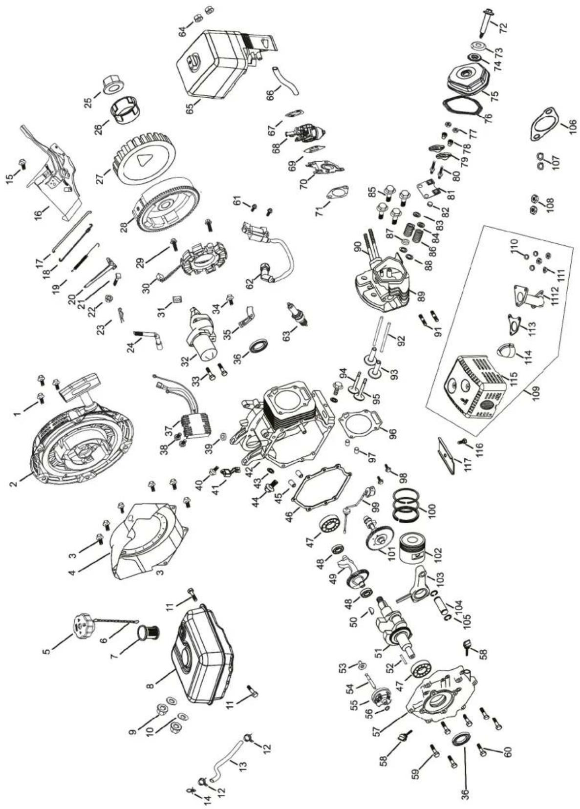

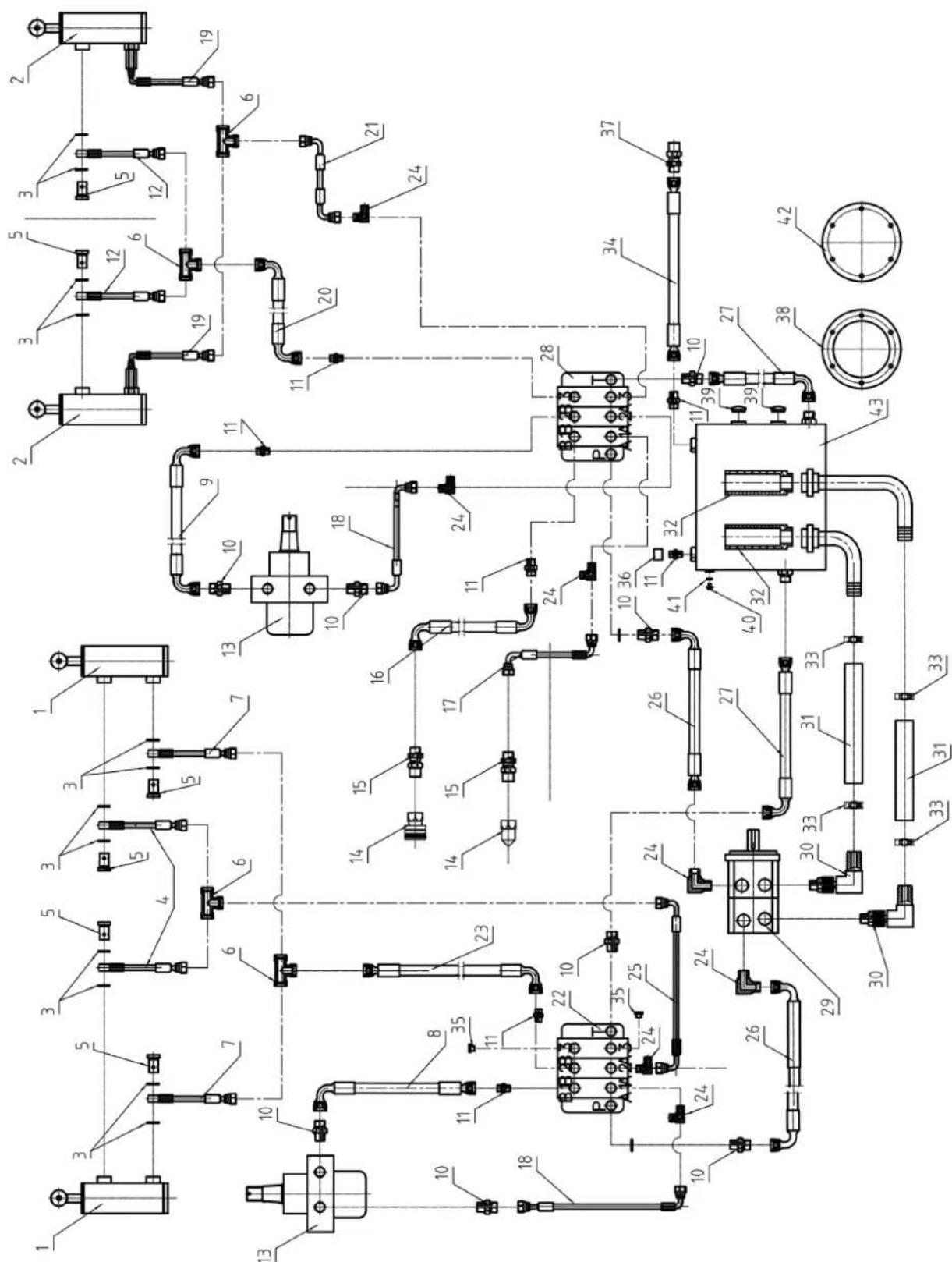
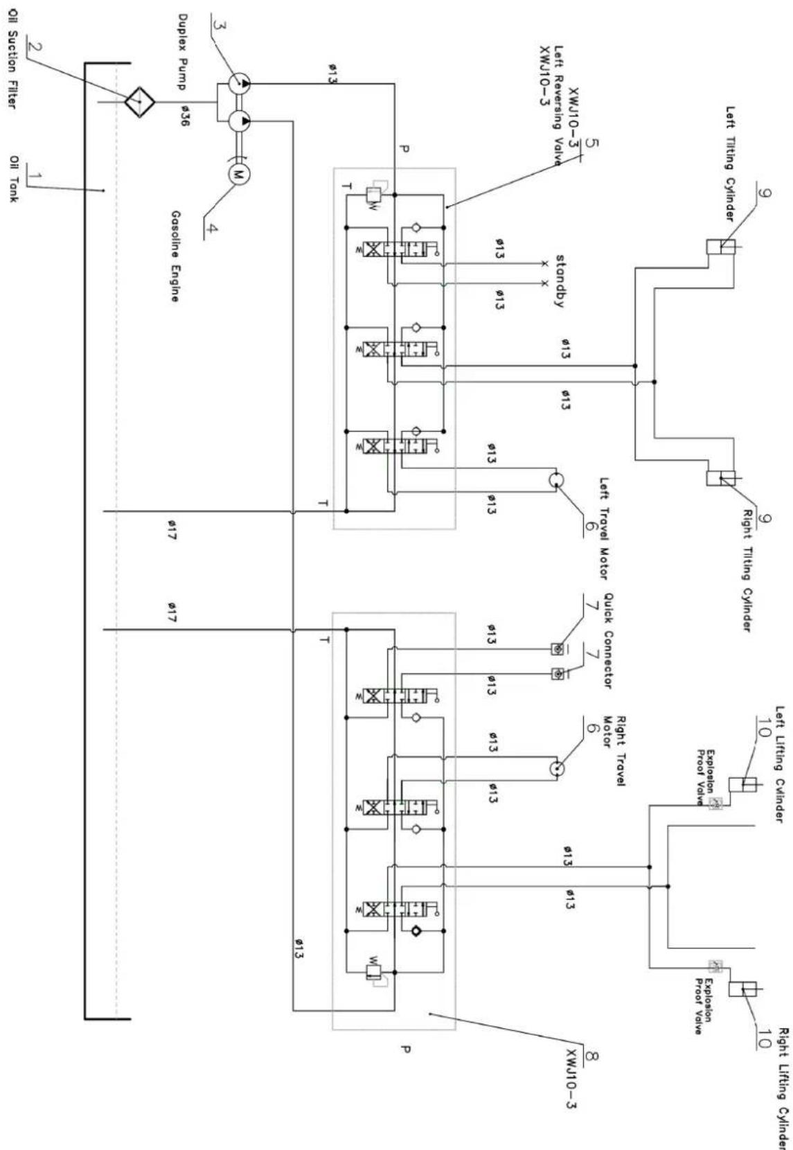
Garantie DE
Obvious defects must be reported within 8 days after receipt of the goods, otherwise the purchaser loses all claims due to such defects. We guarantee our machines, if handled correctly, for the duration of the statutory warranty period from handover in such a way that we will replace free of charge any machine part that demonstrably becomes unusable within this period as a result of material or manufacturing defects. For parts that we do not manufacture ourselves, we only provide a warranty to the extent that we are entitled to warranty claims against the upstream suppliers. The purchaser shall bear the costs of fitting the new parts. Claims for conversion and reduction and other claims for damages are excluded.
Garantie FR


- Garantiebedingungen
- Explanation of the symbols on the product
- Brief explanation - Maintenance item
- Brief explanation - Removing the tool attachment
- Remove tool attachment
- Introduction
- Manufacturer:
- Dear Customer
- Note:
- Product description (Fig. 1-35)
- Scope of delivery (Fig. 1-35)
- Item Quantity Designation
- Proper use
- Improper use
- Explanation of the signal words in the operating manual
- DANGER
- WARNING
- CAUTION
- ATTENTION
- Safety instructions
- Attention!
- Follow the safety instructions
- Familiarising yourself with the product
- Working range
- Personal safety
- Operation and care
- Safety instructions when children are present
- Special safety instructions
- Before use
- Safe operation
- Working on slopes
- Safety instructions for the rubber crawler chassis
- Work complete
- Fire protection
- Hydraulic hazards
- Danger of burning!
- Emergency measures
- Electric shock
- Damage to a power line
- Damage to a gas pipe
- Damage to a fibre optic cable
- Fire involving the product
- Perform an emergency shutdown immediately.
- Loading and unloading products safely
- Lifting the product safely
- Danger to life!
- Danger of crushing!
- Handling fuel
- Risk of explosion!
- Battery safety
- Safety instructions for handling batteries
- Residual risks
- The product has been built according to state-of-the-art and the recognised technical safety rules. However, individual residual risks can arise during operation.
- Technical data
- Noise and vibration
- Keep the noise level and vibration to a minimum!
- Unpacking
- Tool required:
- Removing the transport frame (18) (Fig. 3)
- Lifting the product (Fig. 3)
- Notes:
- Assembly
- Fitting the holders (3) (Fig. 4)
- Before commissioning
- Product damage!
- Environmental damage!
- Risk of fire and explosion!
- Health hazard!
- Filling up with engine oil (Fig. 5)
- Opening/closing the engine cover (2) (Fig. 6)
- Opening:
- Closing:
- Filling in fuel (Fig. 6)
- Connecting/disconnecting a battery (9d) (Fig. 7)
- To connect the battery:
- To disconnect the battery:
- Operation
- Safety pedal (5a) (Fig. 8)
- Overload switch (13c) (Fig. 9)
- Explanation of the control panel (12) (Fig. 9)
- Operating display (12a):
- Button (LED headlight) (12b):
- Button (horn) (12c):
- Explanation of the controller (Fig. 10, 19, 20, 23)
- Left operating lever (11a):
- Right operating lever (11b):
- Hydraulic control lever (11c):
- Replacement hydraulic control lever (11d):
- Switching the product on/off (Fig. 11-18)
- Danger of poisoning!
- NOTE
- In an emergency, leave the operating platform immediately.
- Before starting:
- After starting:
- Using the pull starter (14) to start the engine (Fig. 11-16)
- Starting a cold engine
- Starting a warm engine
- Using the electric starter (13) to start the engine (Fig. 11-15, 17)
- Starting a cold engine
- Starting a warm engine
- Switching off the engine (Fig. 1, 18, 26)
- Operating the travel drive (Fig. 19, 20)
- Driving forward:
- Driving in reverse:
- Changing direction:
- Driving curves and radii:
- Warning about spot turns (turning on the spot)!
- Attach/remove the tool attachment (Fig. 21, 22)
- Attach the tool attachment:
- Scan the QR code below to access the operating manuals for the various tool attachments.
- Connecting hydraulic lines (1) (Fig. 22)
- Operating the tool attachment (Fig. 23)
- To operate the lifting arm (8):
- To operate the tool attachment:
- To operate hydraulic functions of the tool attachment:
- Working instructions
- Reducing rubber track wear (Fig. 1)
- Cleaning and maintenance
- Cleaning
- Cleaning the fuel filter insert (20b) (Fig. 6)
- Maintenance
- Secure the lifting arms (8) in the maintenance position (Fig. 24)
- Maintenance plan
- Maintaining the air filter (22c) (Fig. 25)
- Risk of damage!
- Maintaining the spark plug (23a) (Fig. 25-27)
- Maintaining fuel lines and hoses
- Maintaining the hydraulics (Fig. 28)
- Checking the oil level (Fig. 28)
- Upper sight glass (25a):
- Upper sight glass (25b):
- Relieving the hydraulic oil tank (25) (Fig. 28)
- Topping up the hydraulic oil (Fig. 28)
- Changing the hydraulic oil (Fig. 28)
- Changing the suction filter (25f) (Fig. 28)
- Hydraulic lines
- Servicing engine oil
- Checking the oil level (Fig. 29)
- Oil change (Fig. 29)
- Lubrication points (Fig. 30, 31)
- Servicing battery
- Charging the battery (9d) (Fig. 32)
- Danger due to charging the battery incorrectly!
- Danger of short circuit!
- Charge the battery during the winter 1-2 times to ensure that the full charging capacity is maintained. Incorrect storage can damage the battery.
- Cleaning the crawler (6a) (Fig. 33)
- Storage
- Drain fuel with a fuel extraction pump (Fig. 6)
- Preparing for storage
- Preparation for storage
- Transport
- Load product onto a trailer or lorry via ramps
- Inspect trailer/lorry
- Topping up product
- Risk of tipping during loading and unloading!
- Lifting the product
- Securing the product
- Preparation for transport
- Repair and ordering spare parts
- Important note in the case of repairs
- Disposal and recycling
- Notes for packaging
- You can find out how to dispose of the disused device from your local authority or city administration.
- Fuels and oils
- Troubleshooting
- EU Declaration of Conformity
- Sommaire
- #
- Inhoudsopgave
- Knop (claxon) (12c):
- Indices
- Garantie DE
- Garantie FR
Brand : SCHEPPACH
Model : MKL730
Category : Construction Equipment