
EXC815 - Construction Equipment SCHEPPACH - Free user manual and instructions
Find the device manual for free EXC815 SCHEPPACH in PDF.
| Product type | Mini excavator (construction equipment) |
| Brand | Scheppach |
| Model | EXC815 |
| Engine | 4-stroke, unleaded gasoline (max. 10% bioethanol) |
| Engine power | 6.3 kW / 8.5 hp |
| Fuel tank capacity | 6 L |
| Recommended engine oil | SAE 10W-30 |
| Engine oil capacity | 1.1 L |
| Spark plug | F6TC / F6RTC |
| Operating weight | 637 kg |
| Standard bucket (capacity) | 0.011 m³ |
| Standard bucket (width) | 290 mm |
| Digging force (arm) | 4.2 kN (485 kg) |
| Digging force (bucket) | 8.8 kN (815 kg) |
| Starter | Electric |
| Swing speed | 9.3 rpm |
| Travel speed | 1.7 km/h |
| Gradeability | 15° |
| Ground pressure | 26.5 kPa |
| Track type | Rubber |
| Hydraulic tank | 12 L |
| Hydraulic pump | 8.3 x 2 L/min |
| Sound power level (L_WA) | 93 dB |
| Sound pressure level (L_pA) | 82.5 dB |
| Main functions | Digging, grading, earthmoving, loading |
| Safety | Control lever lock, swing stop bolt, rollover protection |
Frequently Asked Questions - EXC815 SCHEPPACH
User questions about EXC815 SCHEPPACH
0 question about this device. Answer the ones you know or ask your own.
Ask a new question about this device
Download the instructions for your Construction Equipment in PDF format for free! Find your manual EXC815 - SCHEPPACH and take your electronic device back in hand. On this page are published all the documents necessary for the use of your device. EXC815 by SCHEPPACH.
USER MANUAL EXC815 SCHEPPACH
natural_image
Line drawing of a Schneider excavator with tracked tracks and levers (no text or symbols)
EXC815
| DE | Mini-BaggerOriginalbetriebsanleitung | 4 |
| GB | Mini excavatorTranslation of original instruction manual | 62 |
| FR | Mini-pelleTraduction des instructions d'origine | 118 |
| IT | Mini escavatoreLa traduzione dal manuale di istruzioni originale | 176 |
1

Günzburger Straße 69
D-89335 Ichenhausen
Verehrter Kunde,
9. Montage
natural_image
Technical line drawing of a vehicle interior assembly, showing structural components and a zoomed-in view (no text or labels)Warnung!
natural_image
Line drawing of an excavator arm operating on a utility pole (no text or symbols present)natural_image
Technical line drawing of an excavator with a worker on top (no text or symbols)natural_image
Technical diagram of a mechanical assembly with no visible text or symbolsnatural_image
Technical line drawing of a mechanical assembly with two lock icons and a curved component (no text or symbols)10.2 Tägliche Kontrollen
natural_image
Technical line drawing of a vehicle chassis assembly (no text or symbols)natural_image
Technical line drawing of a mechanical device with labeled components and an internal battery symbol (no text or labels present)natural_image
Technical line drawing of a mechanical device with no visible text or symbolsHinweis:
natural_image
Technical diagram of a mechanical assembly with no visible text or symbolsnatural_image
Technical line drawing of a mechanical assembly with no visible text or symbolsAchtung
natural_image
Technical line drawings of mechanical components and a crane arm assembly (no text or symbols)Achtung
natural_image
Technical diagram of a mechanical or electrical component with no visible text, numbers, or symbols.
natural_image
Technical line drawing of an excavator arm assembly (no text or symbols)natural_image
Technical diagram of a heat exchanger or cooling unit with pipes and valves (no text or labels)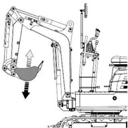
natural_image
Technical line drawing of an excavator with a downward load arrow and component assembly (no text or symbols)12.7 Schwenkbetrieb
⚠ Achtung
natural_image
Technical diagram of a mechanical or fluidic system with pipes and valves, no visible text or symbols
natural_image
Technical line drawing of a mechanical assembly with no visible text or symbolsnatural_image
Technical line drawing of a mechanical assembly with no visible text or symbols
natural_image
Technical line drawing of a mechanical assembly with no visible text or symbolsnatural_image
Technical diagram of a mechanical assembly with no visible text or symbolsnatural_image
Mechanical assembly diagram showing a conveyor belt system with a directional arrow (no text or labels)natural_image
Technical line drawing of a mechanical device with internal components and directional arrows (no text or symbols)

natural_image
Mechanical assembly diagram showing a central rotating component with multiple roller supports and upward/down arrows indicating motion direction (no text or symbols)natural_image
Technical line drawing of an excavator with downward force arrows indicating load or damage (no text or symbols present)Wichtig!
natural_image
Two line drawings of excavators on a slope, one with an upward arrow and the other with an arrow (no text or symbols)Wichtig!
natural_image
Illustration of a bulldozer with a cross symbol crossed out, indicating no movement or restriction (no text or symbols present)natural_image
Diagram showing a device with upward arrows and a mechanical component, no text or symbols present.natural_image
Technical diagram showing a mechanical device with a downward arrow and a right-side view of its internal structure (no text or symbols present)natural_image
Technical diagram showing a mechanical device with internal components and a schematic view of its internal structure (no text or labels)natural_image
Diagram showing a vehicle battery connected to a mechanical assembly with directional arrows (no text or labels)flowchart
graph TD
    A["Top panel with arrow pointing to a device"] --> B["Step 1: Internal components with arrows indicating movement"]
    B --> C["Step 2: Internal components with arrows indicating movement"]
    C --> D["Step 3: Internal components with arrows indicating movement"]
    D --> E["Step 4: Internal components with arrows indicating movement"]
natural_image
Technical line drawing of an excavator on a tracked ground surface (no text or symbols)12.18 Parken am Hang
⚠ Warning!
natural_image
Technical line drawing of an excavator on a sloped terrain (no text or symbols)natural_image
Technical line drawing of an excavator with mounted equipment and a worker on top (no text or symbols)
natural_image
Technical line drawing of a mechanical assembly with no visible text or symbols
natural_image
Technical diagram of a mechanical assembly with no visible text or symbols
natural_image
Cartoon illustration of a front-end loader dumping material into a truck (no text or symbols)natural_image
Line drawing of an excavator on a dump truck, no text or symbols presentGefahr!
natural_image
Illustration of a worker inspecting a dump truck with upward arrows indicating loading or damage (no text or symbols)natural_image
Line drawing of a mining truck with an excavator on an inclined ramp (no text or symbols)natural_image
Technical line drawing of a mechanical assembly with lock symbols and mesh grid (no text or labels)natural_image
Technical diagram of electrical insulator components with lock symbols and tubing (no text or labels)natural_image
Simple line drawing of a dump truck with an excavator and wheels, no text or symbols presentnatural_image
Silhouette of a hand holding two cylindrical objects with motion arrows indicating movement (no text or symbols)natural_image
Silhouette of a human head with sunglasses and motion lines indicating speed or motion (no text or symbols)18.3 Tägliche Kontrollen
natural_image
Technical line drawing of a truck engine bay with visible components and structural details (no text or labels)natural_image
Technical line drawing of a mechanical assembly with no visible text or symbolsnatural_image
Technical line drawing of a mechanical assembly with an inset showing internal components (no text or symbols)natural_image
Technical line drawing of a mechanical assembly with no visible text or symbols8 (x2)
natural_image
Technical line drawing of a mechanical engine assembly (no text or symbols)Wichtig!
natural_image
Technical line drawing of a mechanical assembly with no visible text or symbolsbar
| Range | Value | |---|---| | 5W-30 | -20 | | 10W-30 | -10 | | 30 | 60 | | Rightward Arrow (30) | 80 | | Rightward Arrow (10W-30) | 100 | | Leftward Arrow (5W-30) | -20 |natural_image
Technical line drawing of a mechanical assembly with no visible text or symbolsnatural_image
Technical line drawing of a vehicle chassis with a grid-patterned panel and mechanical components (no text or symbols)natural_image
Silhouette of a human head with motion arrows indicating sound or perception (no text or symbols)natural_image
Line drawing of a hand using a tool to mark a small object on a grid-patterned surface (no text or symbols)Wichtig!
natural_image
Technical line drawing of a mechanical assembly with rollers and gears (no text or symbols)natural_image
Technical line drawing of a truck's internal components, including a grid box and attached vehicle chassis (no text or symbols)natural_image
Technical line drawing of a mechanical assembly with no visible text or symbols
natural_image
Technical line drawing of a tracked vehicle showing internal components and motion arrows (no text or symbols)
natural_image
Technical line drawing of a tracked vehicle with visible tracks, wheels, and a gear mechanism (no text or symbols)natural_image
Technical line drawing of a tracked excavator with attached boom (no text or symbols)
natural_image
Technical line drawing of an automotive engine bay with internal components and a magnified inset showing internal wiring (no text or labels)
natural_image
Technical line drawing of a mechanical assembly with internal components and a close-up inset showing a component detail (no text or symbols present)natural_image
Technical line drawing of an excavator with tracked vehicle, shown in top and side views (no text or labels)(i) ÜBER FRONT (SCHILD OBEN) kN(kg)
| Höhe (mm) Lastradius (mm) | |||||||
| 0 380 760 | 1140 1520 | 1900 2280 | |||||
| 2400 | |||||||
| 2000 | |||||||
| 1600 1,1 (110) | |||||||
| 1200 1,1 (110) | |||||||
| 800 1,7 (170) 1,1 | (110) 0,8 | (80) | |||||
| 400 1,7 (170) 1,1 | (110) 0,8 | (80) | |||||
| 0 1,7 (170) 1,1 (110) | |||||||
| 400 3,2 (320) 1,7 | (170) 1,1 | (110) | |||||
| 800 1,3 (130) | |||||||
| 1200 | |||||||
natural_image
Technical line drawing of an excavator with tracked blade and mechanical components (no text or symbols)Montage
natural_image
Technical line drawing of an excavator arm and bucket assembly (no text or symbols)natural_image
Technical line drawing of an excavator with attached mechanical components (no text or symbols)Montage
natural_image
Technical line drawing of an excavator arm assembly (no text or labels)Haltekralle 7915001702 (SEPARAT ERHÄLTLICH)
natural_image
Technical line drawing of an excavator with tracked base and control arm (no text or symbols)natural_image
Technical line drawing of an excavator assembly with levers and tracks (no text or symbols)
natural_image
Technical line drawing of an excavator with tracked base and control panel (no text or symbols)natural_image
Technical line drawing of an excavator assembly with levers and tracks (no text or labels)natural_image
Line drawing of an excavator with tracked base and blade assembly (no text or symbols)Montage
natural_image
Technical line drawing of an excavator with levers and tracks (no text or symbols)Baggerdach 7915001704 (SEPARAT ERHÄLTLICH)
natural_image
Technical line drawing of an excavator with tracked base and attached boom (no text or symbols)Montage
Explanation of the symbols on the product
Symbols are used in this manual to draw your attention to potential hazards. The safety symbols and the accompanying explanations must be fully understood. The warnings themselves will not rectify a hazard and cannot replace proper accident prevention measures.
 | Before commissioning, read and observe the operating manual and safety instructions! | |
 | Wear hearing protection. Excessive noise can result in a loss of hearing. | |
 | Wear a safety helmet. | |
 | Wear safety goggles. Sparks created during work or fragments, chippings and dust ejected by the device can case sight loss. | |
 | Keep your hands away! | |
 | Smoking prohibited. No sparks or flames. | |
 | Do not start the engine by short-circuiting the starter connections. | |
 | Do not touch any parts that are still hot from operation. They can cause severe burns. | |
 |  |  Stay out of the area to avoid serious personal injury or death. Stay out of the area to avoid serious personal injury or death. |
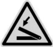 | Watch your hands. |
 | Be careful, objects can be thrown away during use. |
 | Do not use your bare hands to check for possible leaks. |
 | Keep away from moving parts. |
 | Keep away from the fan. |
 | Keep hands away from moving parts. Moving parts can crush and cut. |
 | Keep bystanders away. |
 | Pay attention to safety when working in front of the machine. |
 | Tipping hazard! |
 | Move the bucket close to the ground and remove the key when switching off the excavator. |
 | Switch off the engine, disconnect the spark plug cable and secure that all moving parts are stationary before cleaning, repairing or inspecting the excavator. |
 | Pay attention to the heat of the fan. |
 | Petrol and its vapours are extremely flammable and explosive. |
 | Do not touch any hot parts such as the exhaust etc. |
 | The exhaust gases are dangerous because they contain carbon monoxide. Staying in the area can result in unconsciousness and death. |
 | 3-point lifting device |
 | "Charge battery" warning light |
 | Disconnector earthing cable (negative switch) |
 | Lash down the excavator |
 | Grease |
 | Petrol |
 | Hydraulic oil |
 | Cooling fan |
 | lamp |
 | Horn button |
 | Position horn |
 | Hours |
 | Operating display |
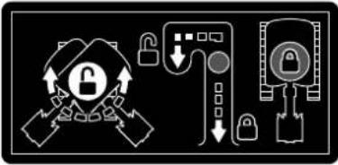 | Advise the operator to lock or unlock the swivelling frame with the swivelling locking pin. |
 | Always check the hydraulic oil level before commissioning the machine. |
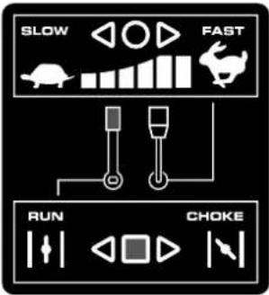 | GAS LEVER The gas lever regulates the engine speed. The throttle lever moves between the Min. and Max. positions |
 | Current output 12V,15A |
 | ENGINE SWITCH ON/OFF/START The engine switch has three positions. OFF - The engine does not start and does not run. ON - The engine is running. Start - The engine ignites. |
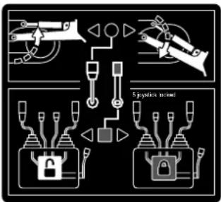 | Pull the black operating lever backwards to raise the levelling blade. Push the lever forwards to lower the levelling blade. |
 | Press the pedal at the front to swivel the boom to the left. Press the pedal at the rear to swivel the boom to the right. |
 | Hold the lever to the right to unlock the seat. Then make the settings. |
 | Manual storage |
 | The product complies with the applicable European directives. |
Table of contents: Page:
- Introduction......69
- Product description (Fig. 1 + 2)....69
- Scope of delivery....69
- Proper use....70
- General safety instructions....70
- Residual risks 72
- Technical data 72
- Unpacking 73
- Assembly....74
- Before commissioning....75
- Commissioning....76
- Operation....79
- Important notes on operating the excavator....87
- After commissioning....87
- Cleaning 88
- Transport 88
- Storage....91
- Maintenance....92
- Repair & ordering spare parts.... 107
- Disposal and recycling 108
- Troubleshooting....109
- Declaration of conformity 127
1. Introduction
Manufacturer:
Scheppach GmbH
Günzburger Straße 69
D-89335 Ichenhausen
Dear Customer,
We hope your new product brings you much enjoyment and success.
Note:
In accordance with the applicable product liability laws, the manufacturer of this product assumes no liability for damage to the product or caused by the product arising from:
- Improper handling
• Non-compliance with the operating manual
• Repairs carried out by third parties, unauthorised specialists
• Installing and replacing non-original spare parts - Improper use
- Failure of the electrical system in the event of the electrical regulations and VDE provisions 0100, DIN 57113 / VDE 0113 not being observed
Note:
Read the whole text of the operating manual before assembly and commissioning.
This operating manual should help you to familiarise yourself with your product and to use it for its intended purpose.
The operating manual includes important instructions for the safe, proper and economic operation of the product, for avoiding danger, for minimising repair costs and downtimes and for increasing the reliability and extending the service life of the product.
In addition to the safety instructions in this operating manual, you must also observe the regulations applicable to the operation of the product in your country.
Keep the operating manual package with the power tool at all times and store it in a plastic cover to protect it from dirt and moisture. They must be read and carefully observed by all operating personnel before starting the work.
The product may only be used by personnel who have been trained to use it and who have been instructed with respect to the associated hazards.
The required minimum age must be observed.
In addition to the safety instructions in this operating manual and the separate regulations of your country, the generally recognised technical rules relating to the operation of such products must also be observed.
We accept no liability for accidents or damage that occur due to a failure to observe this manual and the safety instructions.
2. Product description (Fig. 1 + 2)
- Rear-view mirror
- Operator seat
- Arm cylinder
- Boom
- Arm
- Bucket cylinder
- Bucket
- Bucket joint
- Boom cylinder
- Swivelling bracket
- Levelling blade cylinder
- Levelling blade
- Drive pinion
- Front idle roller
- Ignition lock
- Work light switch
- Horn switch
- Operating display
- Hour counter
- Operating lever for levelling blade
- Operating lever for attachments (right)
- Drive lever (right)
- Drive lever (left)
- Operating lever for attachments (left)
- Petrol engine cold starter
- Throttle
- Boom swivelling pedal
- Safety lever
3. Scope of delivery
The mini excavator is delivered partially assembled and shipped in a carefully packed container. Once you have removed all the parts from the packaging, you should have the following:
| Item Quantity | Designation |
| 1x Main body | |
| 1 2x Rear-view mirror | |
| 2 1x Operator seat | |
| 21/24 2x Operating lever for attachments (right/left) | |
| 22/23 2x Control lever knobs | |
| 1x Handlebar | |
| 1x Spark plug wrench | |
| 1x Operating manual | |
4. Proper use
The mini excavator is suitable for carrying out earthworks and levelling the ground after completion of construction work within the specified technical limits.
The product may only be used in the intended manner. Any use beyond this is improper. The user/operator, not the manufacturer, is responsible for damages or injuries of any type resulting from this.
An element of the intended use is also the observance of the safety instructions, as well as the assembly instructions and operating information in the operating manual.
Persons who operate and maintain the product must be familiar with the manual and must be informed about potential dangers.
The liability of the manufacturer and resulting damages are excluded in the event of modifications of the product.
The product may only be operated with original parts and original accessories from the manufacturer.
The safety, operating and maintenance specifications of the manufacturer, as well as the dimensions specified in the technical data, must be observed.
Please note that our products were not designed with the intention of use for commercial or industrial purposes. We assume no guarantee if the product is used in commercial or industrial applications, or for equivalent work.
The manufacturer is not liable for damage caused by improper use or incorrect operation.
5. General safety instructions
⚠ WARNING - Read all safety information, instructions, illustrations and technical data for this product.
Failure to follow all instructions listed below may result in electric shock, fire and/or serious injury.
Attention!
When using equipment, several safety warnings must be observed to prevent injuries and damage.
For this reason, please carefully read this operating manual / safety instructions. If you hand the device over to another person, please hand over this operating manual / safety instructions as well. We accept no liability for accidents or damage that occur due to a failure to observe this manual and the safety instructions.
⚠️ DANGER
A failure to observe these instructions poses an extreme danger of death or the risk of life-threatening injuries.
⚠ WARNING
A failure to observe these instructions poses a danger of death or the risk of serious injuries.
CAUTION
A failure to observe these instructions poses a minor to moderate danger of injury.
NOTE!
A failure to observe these instructions poses a risk of damage to the engine or other property.
- Familiarise yourself with your machine.
- Read the operating manual carefully and make sure you understand its contents, as well as all labels attached to the machine.
- Familiarise yourself with the area of application, as well as limitations of the machine, and particular sources of danger.
- Make sure that you know all the controls and their function exactly.
- Make sure you know how to stop the machine and quickly disable the controls.
- Do not attempt to use the machine without knowing the exact method of operation and the maintenance requirements of the engine and how to avoid accidents resulting in personal injury and/or property damage.
- Keep other people, particularly children, away from your work area.
Working range
- Never start or operate the machine in an enclosed space. The exhaust gases are dangerous because they contain the odourless and deadly gas carbon monoxide. Operate the machine only in a well-ventilated outdoor area.
- Never operate the machine without good visibility or lighting conditions.
Personal safety
- Do not use the machine if you have taken drugs, alcohol or medication that affects your ability to operate the machine correctly.
- Wear suitable clothing. Wear long trousers, boots and gloves.
-
Do not wear loose clothing, shorts or jewellery of any kind. Tie back long hair so that it is at shoulder height at most. Keep hair, clothing and gloves away from moving parts. Loose-fitting clothing, jewellery or long hair may become caught in the moving parts. Check your machine before starting.
-
Leave protective screens in place and in working order.
- Make sure that all nuts, bolts, etc. are securely tightened.
- Never use the machine if it is in need of repair or in poor mechanical condition. Replace damaged, missing or defective parts before use.
- Check the machine for fuel leaks.
- Keep it in good functional order. Do not use the machine if the engine cannot be switched on and off at the corresponding switch.
- A petrol-driven machine that cannot be controlled via the engine switch is dangerous and must be replaced.
- Before starting the machine, get into the habit of checking that screwdrivers and spanners are away from the area around the machine. A screwdriver or spanner that is still in a rotating device part may result in personal injury.
- Be attentive, watch your actions and use common sense when working with the machine. Do not overextend yourself.
- Do not operate the machine barefoot or with sandals or similar light footwear. Wear safety shoes that protect your feet and improve your grip on slippery surfaces.
- Ensure safe footing and balance at all times. This will allow you to better control the machine in unexpected situations.
- Prevent unintentional start-up. Make sure that the engine switch is switched off before transporting the machine or carrying out maintenance work on the machine. Transport or maintenance work on the machine can lead to accidents if the switch is on.
Safe handling of petrol
- Petrol is very flammable and its gases can explode if they ignite.
• Take safety measures when handling petrol to reduce the risk of serious injury. - Use a suitable petrol can when filling or draining the tank.
- Carry out this work in clean, well-ventilated outdoor areas.
- Do not smoke. Do not allow sparks, naked flames or other sources of fire to get near when filling up with petrol or working with the machine.
- Never fill the tank indoors. Keep earthed, electrically conductive objects, such as tools, away from exposed electrical parts and wires to avoid sparking or arcing. This could ignite petrol gases.
-
Always switch off the engine and let it cool down before refilling the fuel tank. Never remove the fuel filler cap or fill fuel into the tank while the engine is running or while the engine is hot.
-
Do not use the machine if you know there is a leak in the fuel system. Slowly loosen the fuel filler cap to release any pressure in the tank. Never overfill the tank (petrol should never be above the marked maximum fill level). Close the fuel tank securely again with the fuel filler cap and wipe up any spilled petrol.
- Do not use the machine if the fuel filler cap is not screwed tightly shut. Avoid ignition sources near spilled petrol. If petrol has been spilled, do not attempt to start the machine. Move the machine away from the area of the spillage and prevent the formation of ignition sources until the petrol gases have dissipated.
- Store petrol only in containers specially manufactured for this purpose.
- Store petrol in a cool, well-ventilated area away from sparks and naked flames or other sources of ignition. Never store petrol or the machine with a filled tank in a building where petrol gases could reach sparks, naked flames or other ignition sources such as water heaters, ovens, clothes dryers or similar.
- Allow the engine to cool before storing the machine in an enclosed area.
Use and care of the machine
- Never pick up or carry the machine while the engine is running.
- Do not handle the machine violently.
- Use the right machine for your area of application. The right machine will do the job it was designed for better and more safely.
- Do not change the speed governor setting of the engine or over-rev it. The speed control system controls the maximum speed of the engine with maximum safety.
- Do not hold your hands or feet near rotating parts.
- Avoid contact with hot petrol, oil, exhaust gases and hot surfaces. Do not touch the engine or exhaust silencer. These parts become particularly hot during use. They are still hot a short time after the machine is switched off.
- Allow the engine to cool down before carrying out maintenance or adjustment work.
- If the machine starts to make unusual noises or vibrations, switch the engine off immediately, disconnect the spark plug cable and determine the cause. Unusual noises or vibrations are usually a safety sign of faults.
- Only use assembly and accessory parts approved by the manufacturer. Failure to do so may result in injury.
-
Service the machine. Check for misalignment or jamming of moving parts, damaged parts and other conditions that could impair function of the machine. Have the machine repaired before any further use if you find any damage. Many accidents are the result of poorly maintained equipment.
-
Keep the engine and silencer free of grass, leaves, excess grease or soot encrustation to reduce the risk of fire.
- Never pour or splash water or any other liquid onto the machine.
- Keep the handles dry, clean and free of small parts.
- Clean the machine after every use.
- Follow the applicable waste disposal guidelines for petrol, oil etc. to protect the environment.
- Keep the switched-off machine out of the reach of children and do not allow persons who are not familiar with the machine or these instructions to use the machine. The machine is dangerous in the hands of untrained operators.
Service
- Before cleaning, repairing, inspecting or adjusting, switch off the engine and ensure that all moving parts have come to a standstill.
- Always ensure that the throttle lever is in the "off" position. Disconnect the spark plug cable and keep it away from the spark plug to prevent accidental start-up.
- Have your machine serviced by qualified personnel. Use only original spare parts. This ensures that the machine remains safe.
Save all warnings and instructions for future reference.
6. Residual risks
The product has been built according to state-of-the-art and the recognised technical safety rules. However, individual residual risks can arise during operation.
- Health hazard due to electrical power, with the use of improper electrical connection cables.
• Furthermore, despite all precautions having been met, some non-obvious residual risks may still remain. - Residual risks can be minimised if the "Safety Instructions" and the "Intended Use" together with the operating manual as a whole are observed.
- Avoid accidental starting of the product: the operating button may not be pressed when inserting the plug in a socket. Use the tool attachment that is recommended in this operating manual. This is how to ensure that your product provides optimum performance.
- Keep your hands away from the working area when the product is in operation.
7. Technical data
Engine / drive 4-stroke engine
Engine output 6.3 kW/8.5 HP
Fuel Regular grade pet-
rol/lead-free max. 10% bioethanol
Tank capacity 6 l
Recommended engine oil
10W30
Engine oil tank capacity 1.1 l
Spark plug F6TC, F6RTC
Operating weight 637 kg
| Standard bucket | Capacity 0.011m3 | |
| Width 290 mm | ||
| Digging force (arm) | 4.2 kN (485 kg) | |
| Digging force (bucket) | 8.8 kN (815 kg) | |
| Starter | Electric starter | |
| Swivelling speed | 9.3 RPM | |
| Driving speed | 1.7 km/h | |
| Climbing ability | 15° | |
| Ground contact pres- sure | 26.5 kPa | |
| Boom swivelling range | Left | 70° |
| Right | 70° | |
| Crawler links Rubber crawlers | ||
| Pump capacity | 8,3x2 L/min | |
| Hydraulic tank | 12 l | |
| Parking brake | Hydraulic lock | |
Subject to technical changes!
Noise and vibration
⚠ Warning: Noise can have serious effects on your health. If the machine noise exceeds 85 dB, please wear suitable hearing protection.
Noise data
| Sound power level L_WA | 93.0 dB |
| Sound pressure level L_pA | 82.5 dB |
| Uncertainty K_wa/pA | 4.0 dB |
Vibration parameters
| Arm | Vibration a_h | 2.17 m/s ^2 |
| Uncertainty K_h | 0.5 m/s ^2 | |
| Bodywork | Vibration a_h | 7.65 m/s ^2 |
| Uncertainty K_h | 0.5 m/s ^2 |
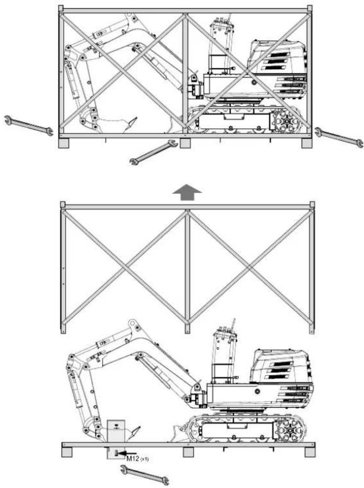
8. Unpacking
- Open the packaging and carefully remove the product.
- Remove the packaging material, as well as the packaging and transport safety devices (if present).
-
Remove the M8 fastening screws from the iron frame and remove the iron frame. Loosen the M12 fastening screws to release the bucket and remove the machine's fastening straps. Lift the machine down.
-
Check whether the scope of delivery is complete.
- Check the product and accessory parts for transport damage. In the event of complaints the carrier must be informed immediately. Later claims will not be recognised.
- If possible, keep the packaging until the expiry of the warranty period.
- Familiarise yourself with the product by means of the operating manual before using for the first time.
- With accessories as well as wearing parts and replacement parts use only original parts. Spare parts can be obtained from your specialist dealer.
- When ordering please provide our article number as well as type and year of manufacture for the product.
⚠ WARNING!
The product and the packaging material are not children's toys! Do not let children play with plastic bags, films or small parts! There is a danger of choking or suffocating!
9. Assembly
If you follow the assembly instructions below, you will have the machine assembled in just a few minutes.
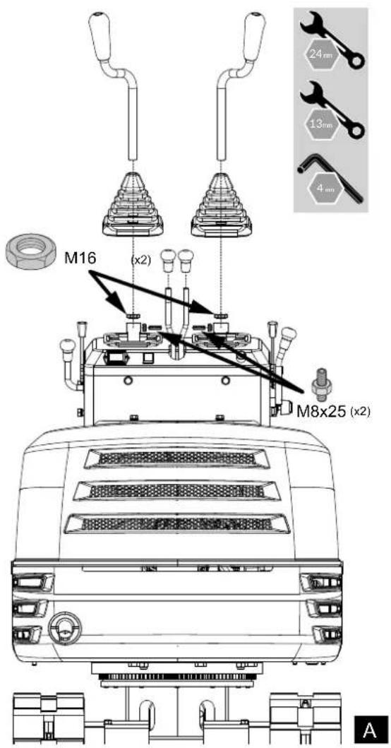
9.1 Fitting the operating levers
- Remove the flat nut M16 from the operating lever and loosen the set screw M8x25 and the nut on the side of the fastening opening.
- Slide the operating lever through the rubber sleeve and the M16 flat nut into the mounting opening on the switch box.
- Turn it to a suitable angle for operation and fasten the M16 flat nut to secure it.
- Fasten the M8x25 set screw and the nut from the side. Repeat these steps to fit the other lever.
- Screw the knobs to the operating levers.
9.2 Structure of the handlebars
- Unscrew the M10x20 screws, washers and spring washers from the switch box.
- Attach the handlebar to the sides of the switch box.
- Align the openings and secure the connection with the screws and washers.

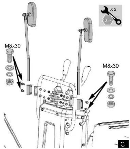
9.3 Fitting the rear-view mirrors
- Remove the M8x30 screws, washers and nuts from the mirror connections.
- Attach the connector to the brackets on the handle bar using the screws, washers and nuts. Ensure that the mirrors are facing backwards as shown in Fig. C.
9.4 Fitting the operator seat
- Open the bonnet and fit the seat from front to rear.
- Bring it into the appropriate position by moving it forwards and backwards.

natural_image
Technical line drawing of a vehicle seat assembly showing front and side views (no text or symbols)Warning!
Always remove the battery before carrying out adjustments on the product.
10. Before commissioning
- Familiarise yourself with the excavator and be aware of its limitations. Read this operator's manual carefully before starting the excavator.
- Observe the danger, warning and caution notices on the machine.
- The crawler width is 690 mm. Work in the right lane.
- Do not operate the excavator under the influence of alcohol, medication or other substances. Tiredness is also dangerous.
- Check the surroundings carefully before using the excavator or installing attachments.
- The excavator must not be used in a contaminated environment.
- Neither the excavator as a whole nor its internal components may be used in potentially explosive atmospheres.
- Pay attention to the distance overhead for electrical cables.

natural_image
Line drawing of an excavator arm operating on a utility pole (no text or symbols present)- Check for underground pipes and cables.
- Check for hidden holes, obstacles, soft ground and overhangs.

natural_image
Technical line drawing of an excavator on a construction ground (no text or symbols)- Do not allow persons to remain within the working area of the excavator.
- Do not allow other persons to use this machine until they have been thoroughly familiarised with the operation and work instructions. Ensure that you have read and understood the operator's manual.
- Do not wear loose, torn or oversized clothing when working with the excavator. Clothing can get caught in rotating parts or controls and lead to accidents or injuries. Wear appropriate safety clothing as required and in accordance with legal regulations, e.g. safety helmet, safety shoes, ear protection, work gloves, etc.
- Do not allow passengers to climb onto parts of the excavator seat during operation.
- Check the mechanical parts for proper adjustment and possible wear. Replace worn or damaged parts immediately. Check nuts and bolts regularly for tightness. (Details can be found under "Care and maintenance".)
- Keep your excavator clean. Heavy soiling, grease, dust and grass can catch fire and cause accidents or injuries.
- Only use approved attachments.
- Before starting the excavator, ensure that it has been filled with 10 petrol, lubricated, oiled and other maintenance work has been carried out.
- Do not modify the excavator as this can lead to unforeseen safety problems.
10.1 Handling the safety devices
10.1.1 Operating lever safety catch
Caution!
When the excavator is not in use or unattended, ensure that you place the bucket on the ground and lock the operating levers. The front attachment can fall off, which is dangerous. Also remove the key.
The safety catch for the operating lever is also located on the right-hand side.

natural_image
Technical diagram of a mechanical assembly with no visible text or symbols10.1.2 Swivelling locking pin
The swivel frame is secured with this bolt. Move the locking pin to the "Locked" position and the swivel frame will lock into the crawler frame.
Note: Before locking the locking pin, make sure that you position the swivel frame and the crawler frame parallel to each other.

natural_image
Technical line drawing of a mechanical assembly with two lock icons and a curved component (no text or symbols)10.2 Daily checks
To avoid damage, it is important to check the condition of the excavator before starting up.
Caution!
Only carry out maintenance work on the excavator on level ground with the engine switched off and the safety devices in the "Locked" position.
10.2.1 Controls
- Walk around the excavator and check for visible damage and wear. Check the fuel level.
- Check the oil level.
- Check the hydraulic oil level.
- Check the air filter for blockages.
- Check the hour counter.
- Check the lighting system.
- Check the condition of the hazard, warning and caution labels. (See "DANGER, WARNING AND CAUTION LABELS" in "SAFE OPERATION".)
11. Commissioning
Attention!
Always make sure the product is fully assembled
before commissioning!
- Get on and off the machine in a safe manner. Always look in the direction of the machine. Always use the handrails and existing steps and keep your balance. Do not hold on to the control levers and switches. Do not jump from the stationary or moving machine.
- Only start and control the excavator from the operator's seat. The driver must not lean out of their seat when the engine is running.
- Before starting the machine, make sure that all operating levers are in the neutral position.
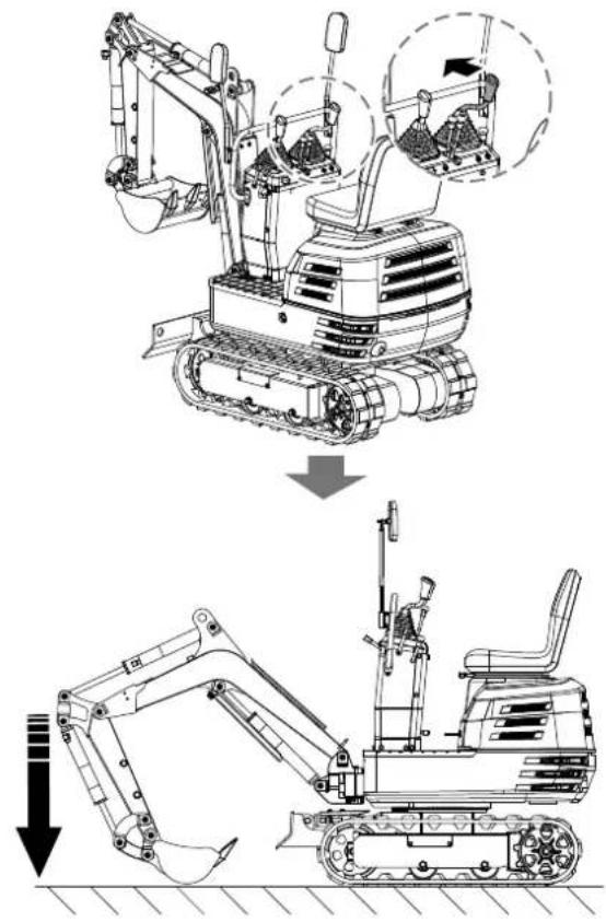
- Do not start the engine by bridging the connections of the starter motor. Do not attempt to bypass the ignition lock, otherwise the engine could start suddenly and the excavator could start moving.
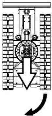
- Ensure that the levelling blade is at the front. (The levelling blade must be raised.) If the swivel frame has been rotated by 180^ , i.e. the levelling blade is at the rear from the operator's point of view, the direction of travel is opposite to the direction of travel of the levers. (If the drive lever is moved forwards, the excavator moves backwards as seen by the operator.)

natural_image
Technical line drawing of a vehicle suspension system with no visible text or symbols-
Do not run the engine in closed or poorly ventilated spaces. Carbon monoxide is colourless, odourless and deadly.
-
Leave all safety elements and cladding in place. Replace damaged or missing safety devices.
-
Precautionary measures against overturning. Keep away from steep slopes and embankments to ensure safe operation. Do not swivel the bucket downwards. Lower the levelling blade when digging. Keep the bucket as low as possible when travelling uphill. Turn carefully on slopes. Do not keep the excavator close to the edges of trenches and embankments, as the earth could give way due to the weight of the excavator.
-
Always pay attention to where the excavator is moving. Keep an eye out for obstacles.
-
Keep sufficient distance from ditches and bank edges. Protection of children! If the operator does not pay attention to the presence of children, tragic accidents can occur. Children are generally attracted to machines and their activities.
-
Never assume that children will stay where you last saw them.
-
Keep children away from the work area and leave them under the supervision of a responsible adult.
-
Pay attention and switch off your machine if children enter the work area.
-
Never transport children on your machine. There is no safe place for them there. They could fall down and be run over or interfere with the controls of your machine.
-
Do not allow children to operate the machine, even under adult supervision.
-
Never allow children to play on the machine or its attachments.
-
Take extra care when reversing, look behind and down and make sure the area is clear before you start moving.
-
If possible, park the machine on firm, flat and level ground. Lower the attachments to the ground, remove the key from the ignition lock and wedge the crawlers.
11.1 Starting the engine
Start the engine as follows:
- Ensure that the petrol valve is in the "Open" position.

- Before starting the engine, make sure that all control levers are in the neutral position.
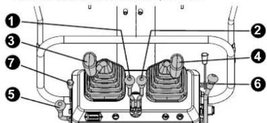
(1) Drive lever (left)
(2) Drive lever (right)
(3) Attachment operating lever (left)
(4) Attachment operating lever (right)
(5) Throttle
(6) Operating lever for levelling blade
(7) Throttle for petrol engine
-
Pull the throttle lever back to the end
-
Insert the key into the ignition lock and turn it to the "ON" position.

- Pull out 1/3 of the throttle handle before starting. Pull the air regulator handle back down and set the start key to "ON" for five seconds to start. When the petrol engine starts, the left-hand air regulator handle resets. (Note that the petrol engine can be started when the vehicle is warm without pulling the air regulator handle).
- Let go when the engine has started. The key automatically returns to the "ON" position.
- Check whether the battery indicator has gone out. Switch off the engine and determine the cause if the battery indicator has not gone out.

natural_image
Technical line drawing of a mechanical device with no visible text or symbolsIf the battery indicator does not light up, first check whether the fuse has blown. If the fuse has been replaced with a new one and is working normally, the battery may be flat and may need to be recharged. If the fuse still blows after replacement, the circuit must be repaired by professional maintenance personnel.
Hour counter
The hour counter shows the total operating hours of the excavator.
Reading the counter
The counter counts up by 1 for each hour of operation. The electrical counter continues when the engine stops and the key is still in the "ON" position.

natural_image
Technical line drawing of a mechanical device with no visible text or symbols11.2 Checkpoints after starting the engine
Check the following points after starting the engine, but before starting work:
- Move the throttle lever to the "LOW" position and allow the engine to idle for approx. 5 minutes. This warms up the engine oil and allows it to penetrate all parts of the engine.
Note: This operation in idle mode is usually called "warming up".
- After the engine has warmed up, check as follows:
- The "Battery charge" warning light goes out when the engine accelerates.
- The colour of the exhaust gases is normal and no abnormal noises or vibrations can be heard.
• No liquid escapes from the pipes or hoses.
Stop the engine immediately if any of the following circumstances occur:
- The speed of the engine suddenly increases or decreases.
- Sudden abnormal noises.
• The exhaust fumes are black.
Attention
In these cases, the excavator must be checked and maintained in accordance with the dealer's instructions.
11.3 Starting the engine when cold
Attention
Ensure that the safety lever is locked during warm-up.
- Pull the throttle lever out by 1/3.
- Pull the air regulator handle back down and the start key to "ON" for five seconds to start. When the petrol engine starts, the left-hand air regulator handle resets. (Note that the petrol engine can be started when the vehicle is warm without pulling the air regulator handle).
- Release the key when the engine has started. It automatically returns to the "ON" position.
Note: After starting the engine, allow it to warm up for about 10 minutes without load. If the temperature of the hydraulic fluid is too low, the function will be impaired. Do not use the excavator under full load until the engine has warmed up sufficiently.
11.4 Switching off the engine
⚠ Warning!
Do not leave the bucket or levelling blade raised, as someone could accidentally touch the levers and cause serious accidents. Lower all attachments to the ground, otherwise accidents may occur.
Allow the engine to idle for about 5 minutes to cool down.
- Move the throttle lever to the idle position.
- Carefully lower the attachments to the ground using the levers.
- To stop the engine, turn the key to the "OFF" position and remove the key.
11.5 Shutting the petrol valve
Caution
In an emergency or if the engine is still running when idling and the key is in the "OFF" position, proceed as follows.
- Open the bonnet, push the switch-off lever back and hold it until the engine stops.

Note:
Contact your dealer if the engine cannot be switched off with the key.
12. Operation
12.1 Checking the controls during operation
Switch off the engine immediately in the following cases:
Pay attention to the following points after starting the engine, but before starting work:
- The speed of the engine suddenly increases or decreases.
- Sudden abnormal noise development.
• The exhaust gases suddenly become very dark.
Observe the following controls during operation to ensure normal function.
⚠ Warning!
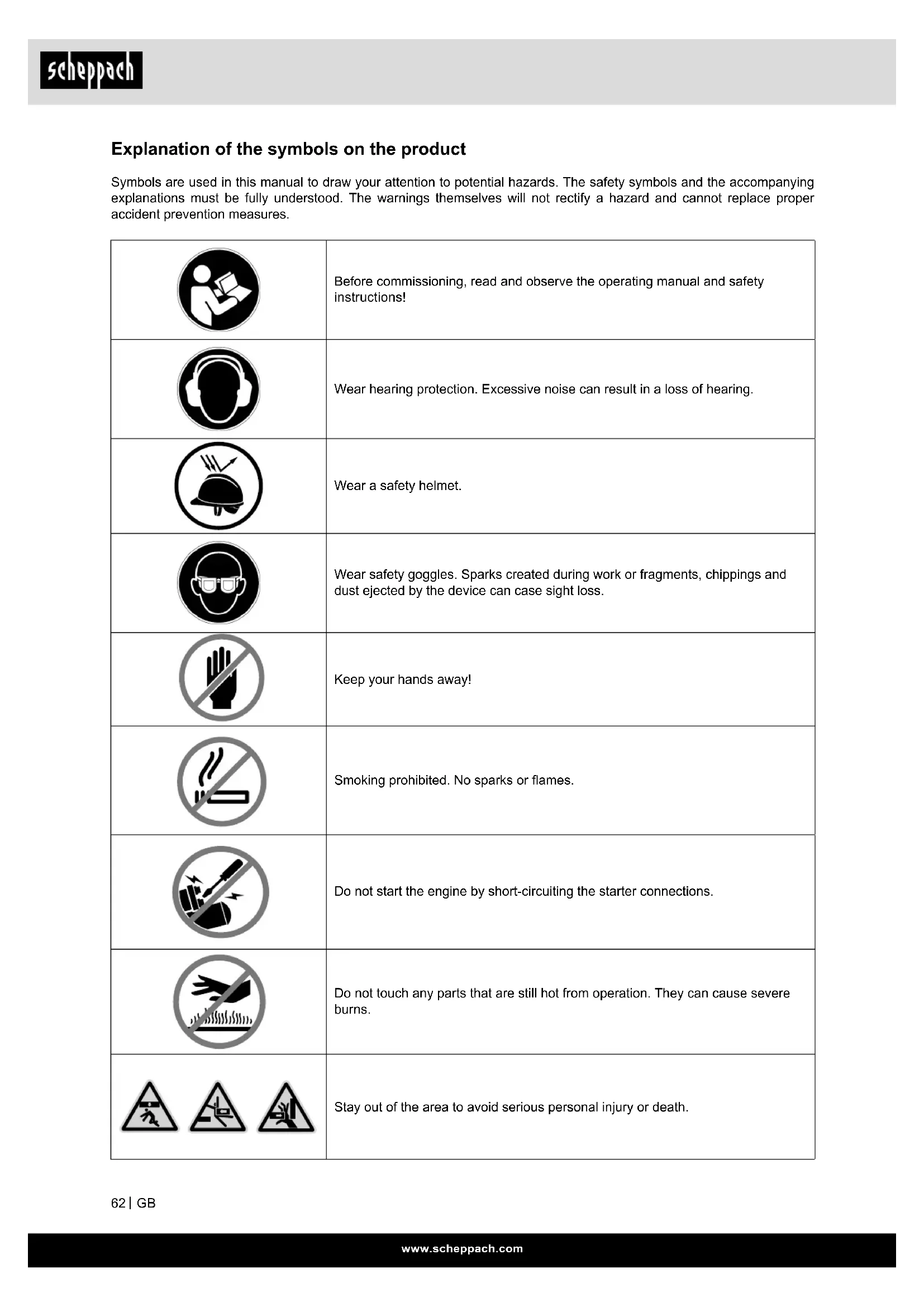
Push the right-hand handle bar forwards if the engine stops suddenly so that the bucket falls down and there are no malfunctions that could lead to accidents due to the bucket falling down.
12.2 Running in the new excavator
The service life of the new excavator is influenced by operation and maintenance. Your new excavator was carefully inspected and tested before it left the factory. Nevertheless, all moving components must be run in during the first 50 hours. Do not work at full speed and load during this time. It is extremely important to run in the excavator correctly in order to achieve its full performance and service life. The following points should always be observed during the running-in phase. Do not work at full speed or full load for the first 50 working hours.
- Allow the engine to warm up sufficiently in the cold.
- Do not increase the engine speed more than necessary.
Oil change during the running-in phase.
Lubricating oil plays a particularly important role during the running-in phase of the excavator.
The various moving parts have not yet been run in, so that many fine metal particles develop which can cause damage or shorten the service life of many components. Pay attention to the intervals between oil changes and carry them out sooner rather than later. See "Care and maintenance" for more details on oil change intervals.
12.3 Starting up
Caution
The excavator may only be used by persons who are familiar with its operation. Do not allow anyone other than the operator to work with the excavator.
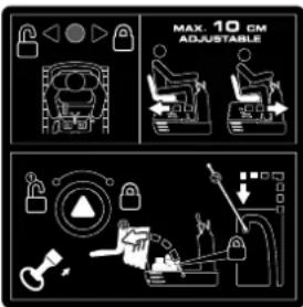
12.3.1 Adjusting the operator's seat
Caution
Before adjusting the operator's seat, make sure that nobody puts their hands on the bonnet behind the seat.
After adjusting the seat, make sure that the seat adjustment is engaged.
- Move forwards and backwards: Move the seat forwards and backwards while holding the adjustment lever.
- Move the locking lever to the position "Unlock".
- Move the locking lever to the "unlock" position and lift the lower side of the bucket 20 cm to 40 cm off the ground.

natural_image
Technical diagram of a mechanical assembly with no visible text or symbols12.3.2 Work light switch
When the key is in the "ON" position, the lights are switched on by tapping the switch.

natural_image
Technical line drawing of a mechanical assembly with no visible text or symbols⚠ Attention
The brightness in the vicinity of the machine must be above 500 lux.
12.3.3 Night mode
Caution
Visibility is limited in the dark, so work lighting alone is not enough. Prepare additional lighting and observe the safety regulations and special regulations for working at night.
12.3.4 Drive lever

| Position of the lever Movement | |
| Front left attachment operating lever | A Extend arm |
| B Retract arm | |
| C Swivel left | |
| D Swivel right | |
| Front right attachment operating lever | 1 Lower the boom |
| 2 Raise the boom | |
| 3 Dig bucket | |
| 4 Empty bucket | |
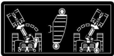
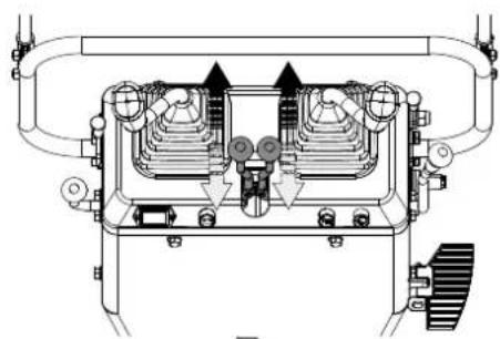
12.4 Operating the boom
To raise the boom, pull the operating lever of the boom backwards. The boom is equipped with a damping cylinder that prevents the excavated material from falling out of the bucket. If the hydraulic oil temperature is low (e.g. immediately after starting the engine), the damper function only starts with a slight delay (approx. 3 to 5 seconds). This is due to the viscosity of the hydraulic oil and is not a sign of a malfunction.
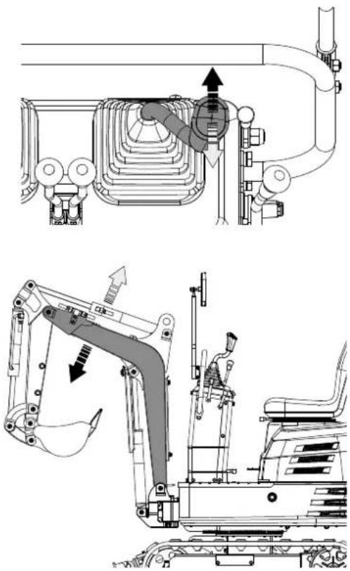
natural_image
Technical line drawings of mechanical components and a crane arm assembly (no text or symbols)⚠ Attention
When lowering the boom, make sure that it does not hit the levelling blade and that the excavator teeth do not touch it.
12.5 Operating the arm
Pull the left operating lever for the attachment backwards and the arm is retracted. Push the operating lever forwards to extend the arm.
Attention
When moving the arm, the movement may pause for a brief moment if the arm is in a vertical position. This is because the maximum load on the arm and bucket is reached in this position and the hydraulic pressure in the cylinder is not high enough. This is a characteristic of the hydraulic system and not a sign of a malfunction.
natural_image
Technical diagram of a mechanical or electrical component with no visible text, numbers, or symbols.
natural_image
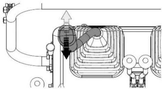
Technical line drawing of an excavator arm assembly (no text or symbols)12.6 Operating the bucket
To dig with the bucket, move the operating lever for the right attachment from the "Neutral" position to the left. Move the operating lever to the right and the bucket is pushed outwards and the contents are poured out.

natural_image
Technical diagram of a heat exchanger or cooling unit with pipes and valves (no text or labels)
natural_image
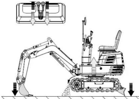
Technical line drawing of an excavator with a downward load arrow and component details (no text or symbols)12.7 Swivelling operation
Attention
When working in groups, always let the others know in advance what you intend to do.
Keep the work area clear!
Important!
Never move the left attachment operating lever abruptly from right to left (or vice versa). According to the law of inertia, this causes a shock load on the swivel motor gearbox and the part-turn motor. In addition, the service life of the excavator is shortened. Remove the swivelling locking pin before carrying out swivelling operations.
- Tilt the operating lever to the left and the upper superstructure will rotate to the left.
- Tilt the operating lever to the right and the upper superstructure will rotate to the right.

natural_image
Technical diagram of a mechanical or electrical component with pipes and a central valve (no text or symbols)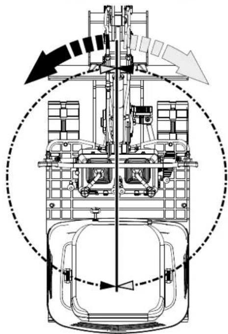
natural_image
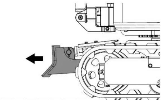
Technical line drawing of a mechanical assembly with directional arrows indicating motion or force (no text or symbols)12.8 Swivelling the outrigger
- Press the pedal at the front to swivel the boom to the left.
- Press the pedal at the rear to swivel the boom to the right.

natural_image
Technical line drawing of a mechanical assembly with no visible text or symbols
12.9 Boom swivelling pedal
⚠ Warning!
Always keep your toes on the edge of the step. Otherwise your toes could get caught between the swivel frame and the boom or boom cylinder.
Caution
If boom swivelling operation is not required, fold the boom swivel pedal forwards to prevent unexpected movements of the pedal.

natural_image
Technical line drawing of a mechanical assembly with no visible text or symbols12.10 Operating the levelling blade
- To raise the levelling blade, pull the operating lever for the levelling blade to the rear. Push the operating lever forwards to lower the levelling blade.

natural_image
Technical diagram of a mechanical assembly with no visible text or symbols- Operate both drive levers with your left hand and the control lever for the levelling blade with your right hand during earthworks.
12.11 Driving
⚠ Warning!
Before starting the engine, make sure that there are no other persons in the vicinity of the excavator. Check the direction of the crawlers before working with the excavator. (Idle roller and levelling blade pointing to the front of the excavator.) Avoid driving across a slope or working sideways on it.
natural_image
Technical line drawing of a mechanical assembly with no visible text or symbols- Set the engine speed from idling to medium speed.
- Raise the levelling blade and hold the bucket 20 to 40 cm from the ground.

12.11.1 Drive lever (right, left)
⚠ Warning!
If the swivelling frame has been rotated by 180^ , i.e. it is at the rear from the operator's point of view, the direction of travel is opposite to the direction of travel of the levers. (If the drive lever is moved forwards, the excavator moves backwards as seen by the operator.)
natural_image
Technical diagram of a mechanical or electrical device with no visible text, numbers, or symbols.

natural_image
Mechanical assembly diagram showing a central rotating component with multiple side supports and upward/down arrows indicating motion direction (no text or symbols)If the drive lever is pushed forwards, the excavator moves forwards and vice versa. The front of the excavator is the side with the levelling blade.
Important!
If the crawlers become clogged with sand or stones when working on soft ground, lift a crawler using the boom, arm and bucket and allow the crawler to turn to shake off sand and stones.
natural_image
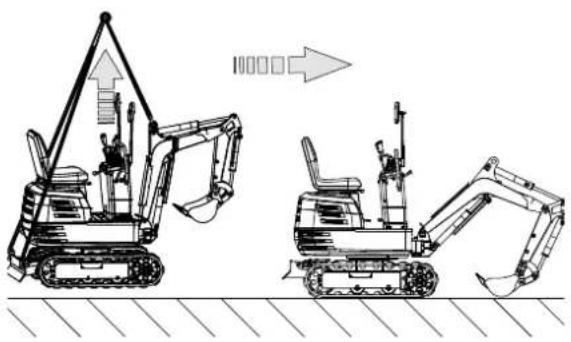
Technical line drawing of an excavator with downward force arrows indicating load or damage (no text or symbols present)Important!
If the excavator gets stuck in the mud while travelling on muddy ground and cannot move, it should be lifted to a safe area using the sling as shown in the illustration below.
natural_image
Two line drawings of excavators on a construction ground, showing different mechanical configurations (no text or symbols present)Important!
The excavator must not be driven on muddy roads if the swivelling platform is perpendicular to the crawlers. Otherwise the crawlers can get stuck in the mud.

natural_image
Illustration of a bulldozer with a black X symbol crossed out, indicating no movement or restriction (no text or symbols present)12.12 Change of direction
Caution
Do not change direction on steep slopes. The excavator could topple over. Watch out for people in the work area before changing direction.
12.13 Turning on the spot
Note
The illustrated movement shows the turning movement with the levelling blade pointing forwards.
If the levelling blade is facing backwards, the direction of rotation is reversed. (For example, press the left (right) lever forwards and the crawler on the right (left) from the operator's point of view moves backwards towards the operator.)
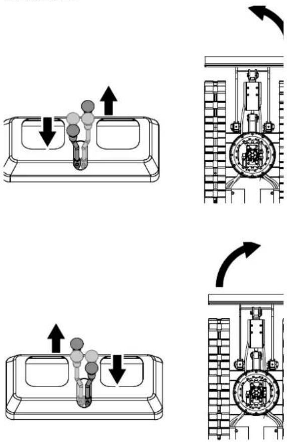
12.14 Changing direction while stationary
- Push the left drive lever forwards and the excavator turns to the right.
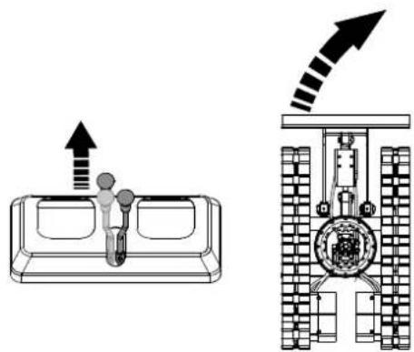
natural_image
Diagram showing a device with upward arrows and a mechanical assembly (no text or symbols)- Pull the left drive lever backwards and the excavator will turn to the left.

natural_image
Technical diagram showing a mechanical assembly with a valve mechanism and a cross-sectional view of the internal structure (no text or labels)12.15 Changing direction while driving
- When driving forwards, set the left drive lever to the neutral position and the excavator will turn to the left.

natural_image
Technical diagram showing a mechanical device with internal components and a schematic view of its internal structure (no text or labels)- When reversing, set the left drive lever to the neutral position and the excavator will turn to the right.

natural_image
Mechanical diagram showing a cam mechanism with no text or symbols, featuring a central gear and directional arrow (no readable text or labels)12.16 Turning on the spot
If both drive levers are activated in opposite directions, both crawlers rotate at the same speed in opposite directions. The axis of rotation is the centre of the excavator.
12.17 Driving uphill and downhill
When driving uphill, keep the lower edge of the bucket approx. 20 cm to 40 cm above the ground. Even if the excavator does not slip easily because of the crawlers, it is safer to let the bucket glide over the ground when travelling downhill. Always select a low speed when travelling uphill and downhill.
[DRIVING UPHILL]

[DRIVING DOWNHILL]

natural_image
Technical line drawing of a tracked excavator on a slope, showing motion direction (no text or symbols)12.18 Parking on slopes
⚠ Warning!
If the excavator is parked on a slope or left unattended, place the bucket on the ground and all operating levers in the neutral position. Block the crawlers with wedges.

natural_image
Technical line drawing of an excavator on a sloped terrain (no text or symbols)13. Important notes on operating the excavator
Caution
Clean the machine after work and lubricate all moving parts. Check the oil level.
Important!
Do not attempt to break concrete or rock by swivelling the buckets sideways. Also avoid moving piles of earth by swivelling the bucket sideways. Avoid the following activities at all costs:
- Lifting by utilising the machine's gravity.
- Compacting gravel or soil by dropping the bucket.
- Lifting with the aid of the machine's driving energy.
Do not attempt to shake off soil adhering to the bucket as explained below. This can damage the machine.
Adhering soil can be shaken off when the bucket is emptied by moving the bucket to the maximum stroke of the cylinder. If this is not enough, extend the arm as far as possible and move the bucket backwards and forwards.
Do not shoot at the levelling blade with the boom cylinder! Ensure that the boom cylinder does not hit the levelling blade when carrying out deep excavation work. If necessary, swivel the uppercarriage so that the levelling blade is at the rear of the machine.
Be careful when retracting the bucket! Avoid hitting the levelling blade when retracting the bucket (for driving or transport).
Avoid collisions! When moving the excavator, take care that the levelling blade does not collide with obstacles such as rocks etc.
Such collisions can significantly shorten the service life of the levelling blade and the cylinder.
Support the machine correctly! Lower the levelling blade completely to the base when stabilising the machine with the levelling blade.
If water or mud reaches over the top of the crawlers, the swivel bearing, the gearbox of the swivel motor and the sprocket can come into contact with mud, water and other foreign bodies.
The excavator must be thoroughly washed with high pressure after each use.
- Thoroughly clean the area around the swivel bearing, the swivel motor gearbox and the gear rim to remove foreign objects.
- Carefully refer to the operator's manual for the correct lubrication procedures for the swivel bearing, swivel motor gearbox and gear rim.
- Reattach the protective cover if it has been removed beforehand.
13.1 Preparation for operation in cold weather
- Replace the engine and hydraulic oil with grades with viscosities suitable for cold weather.
- If the battery is not sufficiently charged, battery performance will drop in cold weather and the battery may freeze. Make sure that the battery is at least 75 % charged after use so that the battery fluid does not freeze. To simplify the next start, we recommend storing the battery in closed or heated rooms.
14. After commissioning
- Place the excavator on hard, level ground.
- Lower the attachments and the levelling blade onto the base.
- Switch off the engine.
- Secure all operating levers.
- Remove the key.
natural_image
Technical line drawing of an excavator with tracked base and attached boom (no text or symbols)
natural_image
Technical line drawing of a mechanical assembly with pipes and components (no text or symbols)Clean the excavator thoroughly after work and wipe it dry. Otherwise, mud and soil can freeze on the crawlers when the temperature drops below 0 °C. Then the excavator cannot be put into operation. Store the excavator in a dry place or on wooden planks or mats if this is not possible. If the excavator is stored on damp or muddy ground, the crawlers may freeze overnight. Then the excavator cannot be put into operation. In addition, the piston rods of the hydraulic cylinders must be rubbed dry. Otherwise, serious damage may occur if dirty water penetrates the seals.
15. Cleaning
Danger!
Pull out the battery before carrying out any cleaning work.
- Keep protective devices, air vents and the motor housing as free of dust and dirt as possible. Rub the product clean with a clean cloth or blow it off with compressed air at low pressure.
• We recommend that you clean the product directly after every use. - Clean the product at regular intervals using a damp cloth and a little soft soap. Do not use any cleaning products or solvents; they could attack the plastic parts of the product. Make sure that no water can penetrate the interior of the product. Water penetration increases the risk of an electric shock.
16. Transport
-
Observe all regulations regarding the transport of excavators on public roads.
-
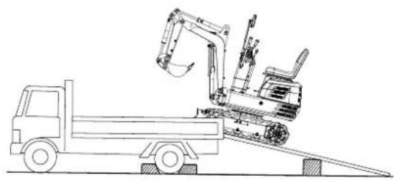
Use sufficiently long and stable ramps when loading onto a lorry. (For details, see "TRANSPORTING THE EXCAVATOR ON A LORRY".) The machine can also be lifted onto the lorry. (For details, see "IFTING THE EXCAVATOR".)
- Do not change the direction of travel and prevent yourself from overturning. Therefore, do not attempt to swivel the attachment across the loading ramps.
- Swivel the uppercarriage to the rear of the lorry and attach the swivelling locking pin. Lower the attachment onto the loading surface, release the pressure from the hydraulic system and secure the boom with the lever. Block the crawlers with blocks and tie down the excavator. After loading the excavator, lash the chassis of the excavator to the lorry with a strong steel cable.


natural_image
Technical diagram of a mechanical assembly with no visible text or symbols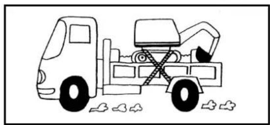
natural_image
Simple line drawing of a truck with an excavator and wheels, no text or symbols present- Do not brake abruptly when the excavator is loaded. Fatal accidents could occur.
16.1 Transporting the excavator on a lorry
Danger!
Do not change direction when the excavator is on the ramp. If a change of direction is required, drive off the ramp completely and change direction.
Danger!
If driving forwards or backwards onto the lorry or if you swivel the uppercarriage, make sure that neither the cab nor the side walls of the lorry are damaged.
natural_image
Line drawing of an excavator on a dump truck, no text or symbols presentDanger!
When the excavator reaches the point between the ramps and the loading surface of the lorry, stop and drive very slowly until the excavator is in a horizontal position.
Danger!
Only move the excavator onto the lorry with the arm fully retracted. Otherwise, the cab of the lorry could be damaged if the uppercarriage is swivelled around.
Danger!
Do not lift the machine with the boom to load or unload the excavator onto the lorry. This may lead to dangerous situations.
⚠ Warning!
Lower the bucket and levelling blade onto the loading surface of the lorry after the machine has been loaded onto the lorry. Secure the swivel frame with the swivelling locking pin.
Prepare a platform for loading or unloading the excavator. Proceed as follows when using ramps:
- Activate the lorry's parking brakes and block the drive wheels from both sides.

natural_image
Illustration of a construction worker using a dump truck to lift or push a slope (no text or symbols)- Use mounting plates to secure the ramp properly. Attach the ramps directly to the loading surface of the lorry.
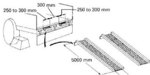
- Use blocks or struts under the ramps and on the loading surface for additional safety.

natural_image
Line drawing of a construction vehicle with an excavator on an inclined plane (no text or symbols)- Align the ramps and crawlers completely and then drive the excavator slowly up the ramps with the levelling blade facing forwards. Swivel the upper-carriage towards the rear of the truck when the crawlers are completely on the loading surface of the lomy.
- Secure the swivel frame with the swivelling locking pin.

natural_image
Technical line drawing of a mechanical assembly with lock icons and a door handle (no text or symbols)- Lower the bucket and levelling blade onto the loading surface of the lorry and secure the boom with the lever before climbing off.

natural_image
Technical diagram of electrical insulator components with no visible text or symbols- Block the crawlers and lash down the excavator.

natural_image
Simple line drawing of a dump truck with an excavator and pile of waste (no text or symbols)- Before unloading, remove the locking pin and then lift the levelling blade and bucket off the loading surface.
16.2 Lifting the excavator
Danger!
The correct instructions for safe handling can be found here. Read these carefully before moving the machine. Ensure that the operating personnel read the operator's manual carefully.
Basics for lifting with chains/belts:
- The crane is lifted and operated in accordance with the guidelines described.
- As the tools mentioned in this manual are for reference only, the standards regarding strength, control and other details are based on the respective applicable guidelines.
Safety aspects when lifting with chains/belts:
- Do not lift any loads if this exceeds the maximum load capacity of the crane.
-
Select the correct rigging for the weight, size and shape of the load.
-
First determine the centre of gravity of the load, position the hook directly above the load and lift the load so that the centre of gravity of the load is as low as possible.
- Steel cables must be fastened in the centre of the hook.
- The load must be lifted vertically from the ground.
- Do not enter the work area under suspended loads and do not move the load over other people. The load must be moved in an area where the balance can be easily equalised.
General guidelines for lifting:
⚠ Warning!
Only lift the excavator at the 3 points shown.
Lifting position (see figure below)
- Pull the boom fully backwards.
- Fully retract the arm.
- Fully retract the bucket.
- Swivel the boom to the centre position.
- Swivel the uppercarriage 180° to ensure that the levelling blade is at the rear as seen by the operator.
- Insert the swivelling locking pin.
Fastening the chains/straps.
- Always hook the excavator in at three points (on the boom and to the right and left of the levelling blade).
⚠ Warning!
The levelling blade must be raised.
- When attaching the straps, use a shackle at each stroke opening.
- Use padding materials where the belts touch the machine.
Tackle
Use components of sufficient strength.
Lifting
- Lift slowly and safely.
- Do not climb onto the excavator when lifting it.
- Lift the excavator horizontally. (Change the connections as required).

17. Storage
Caution
Do not clean the excavator with the engine running.
Caution
To avoid the risk of exhaust poisoning, do not run the engine in a closed building without good ventilation.
Caution
Remove the key from the ignition lock during storage to prevent unauthorised persons from operating the excavator and injuring themselves.
Observe the following sequences if the excavator is to be stored for an extended period:
-
The entire excavator should be thoroughly cleaned and stored indoors. If the excavator has to be stored outdoors, lay out wooden planks on a level surface, place the excavator on them and cover it completely.
-
Change the oil and lubricate the excavator.
-
Lubricate the visible sections of the piston rods particularly well.
-
Remove the battery and store it indoors.
Important!
Wash the excavator with the engine switched off. If you wash the excavator while the engine is running, water can enter the air filter through the inlet and cause engine problems. Wash the excavator carefully to avoid splashing water over the air filter.
Follow the procedures below if the machine is to be put into operation after a long period of storage.
-
Wipe the grease off the hydraulic cylinder rods.
-
Switch on the engine and activate the attachments and the drive mechanism without load to allow the hydraulic oil to circulate. (If the machine is stored for longer than one month, carry out steps (1) and (2) every month.)
18. Maintenance
Place the machine on a level, firm surface before starting maintenance work. Lower the attachments to the ground, stop the engine and release the cylinder pressure by operating the levers. When dismantling hydraulic parts, ensure that the hydraulic oil has cooled down sufficiently to prevent burns.
Start the maintenance work carefully, i.e. loosen the screws slowly so that no oil splashes out.
- Allow the excavator to cool down sufficiently before working on the engine, the exhaust system, the heat protection system and the hydraulics.
- Always switch off the engine when filling it with petrol. Avoid spilling and overfilling with petrol.
- Smoking is prohibited when refuelling and handling the battery! Keep sparks and fire away from the petrol tank and battery. Flammable gases escape from the battery.
- If the battery is empty, the machine can be started by pulling the cable.
- Avoid short-circuiting the battery. Always remove the earth cable first and connect the positive cable first.
- Have a first aid kit and a fire extinguisher ready at all times.
- Leaking hydraulic fluid has sufficient pressure to penetrate the skin and cause serious injury. Leaks from tiny holes can be completely invisible. Never check for possible leaks with your bare hands. Always use a piece of wood or cardboard. We recommend the use of a face mask or eye protection. If injuries occur due to leaking hydraulic fluid, contact a doctor immediately. This liquid can cause gangrene or severe allergic reactions.

natural_image
Silhouette of a hand holding a bent pipe with motion arrows indicating flow or movement (no text or symbols)- Do not throw the battery away to prevent battery fluid containing heavy metals from leaking out.
- Observe all laws and regulations regarding the disposal of used oil, coolants, solvents, hydraulic fluids, battery acid and batteries.
- To prevent fires, do not heat up the hydraulic components (tanks, pipes, hoses, cylinders) until they have been rinsed and washed.
- Use a face mask or eye protection to protect the eyes and respiratory tract from dust and other foreign bodies.

natural_image
Silhouette of a human head with sunglasses and motion lines, no text or symbols present- Do not crawl under the excavator if it is only supported by the boom and arm or the levelling blade. The excavator can tip over or sink due to loss of pressure in the hydraulics. Always use safety struts or other suitable supports.
- Do not use any parts that are lined with asbestos. Do not use these types of parts even if they can be installed.
- Fire protection. The excavator and some attachments contain components that are very hot under normal working conditions. The main source of high temperatures is the engine and the exhaust system. The electrical system can be a source of sparks and flashover if damaged or improperly maintained. The following fire safety guidelines will help you to keep your devices running efficiently and minimise the risk of fire.
- Blow off any accumulations of foreign matter near the hot engine exhaust components such as the petrol engine cylinder head and exhaust manifold as well as the exhaust pipe and silencer more frequently if you are working in difficult conditions.
- Remove all flammable debris such as leaves, straw, pine needles, twigs, bark, small wood chips and other flammable materials from inside the machine's protrusions and lower structures and areas near the engine.
- Inspect all petrol and hydraulic lines for wear or poor condition. Replace them immediately if they start to leak.
- Check the electrical cables and connections regularly for damage. Repair any loose or frayed cables before commissioning the machine. Clean all electrical connections and tighten them if necessary.
- Check the exhaust system daily for signs of leaks. Check for broken pipes and silencers as well as loose or missing screws, nuts and clamps. If leaks or broken parts of the exhaust system are found, the repairs must be carried out before commissioning.
- Always keep a multi-purpose fire extinguisher on or near the machine. Familiarise yourself with the operation of the fire extinguisher.
18.1 Maintenance intervals
| Components Measure | Measure | Operating hours | |||||||||||||
| 50 100 | 150 | 200 | 250 | 300 | 350 | 400 | 450 | 500 | 550 | 600 | 1000 | 2000 | |||
| Fuel Check Daily | |||||||||||||||
| Engine oil | Check Daily | ||||||||||||||
| Change | X | X | X | X | X | X | X | X | X | X | X | X | X | X | |
| Hydraulic oil | Check Daily | ||||||||||||||
| Change | X | ||||||||||||||
| Lubrication points | Check Daily | ||||||||||||||
| Fan propeller | Check Daily | ||||||||||||||
| Electrical wiring | Check Daily | ||||||||||||||
| Air cylinder; Fan propeller | Clean | Daily | |||||||||||||
| Machine | Clean | Daily | |||||||||||||
| Battery | Check | X | X | X | X | X | X | X | X | X | X | X | X | X | X |
| Lubrication of the swivel bearing teeth | Check | X | X | X | X | X | X | X | X | X | X | X | X | X | X |
| Air filter element ** | Cleaning | X | X | X | X | X | X | X | X | X | X | X | X | X | X |
| Change | X | X | X | X | X | ||||||||||
| Lubrication of swivel bearing | Check | X | X | X | X | X | X | X | X | ||||||
| Fuel line and hoses | Check | X | X | X | X | X | |||||||||
| Change | Every 2 years | ||||||||||||||
| Hydraulic return filter | Change | X | X | ||||||||||||
| Hydraulic intake filter | Change | X | X | ||||||||||||
| Spark plug | Check | X | X | X | X | X | X | X | X | X | X | X | X | X | X |
| Change | X | X | |||||||||||||
** Clean the air filter element more often if the machine is operated in dusty conditions.
18.2 Opening and closing of components
18.2.1 Opening/closing the bonnet
Caution
Do not open the bonnet until you have switched off the engine.
Caution
Do not touch the silencer or the exhaust pipe, as this can cause serious burns.
Turn the key in the direction of the arrow as shown in the figure below to open the bonnet.
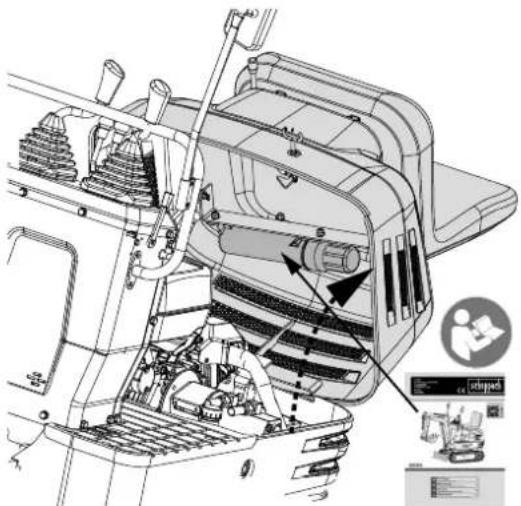
Keep the tools and the operator's manual in the manual storage area

18.3 Daily checks
For your own safety and to ensure a long service life of the machine, careful inspections should be carried out before each use.
18.3.1 Checking the petrol level
Caution
Switch off the engine before filling with petrol.
Caution
Do not smoke when filling with petrol.
Important!
Use unleaded petrol with an octane rating of 86 or higher.
- Check the fill level in the petrol tank.
- Open the fuel filler cap and top up with petrol.

natural_image
Technical line drawing of a truck engine bay with visible components and structural details (no text or labels)Tank capacity: 6 litres
Important!
Always top up with petrol after a working day.
Important!
See "FLUSHING THE FUEL SYSTEM" in "OTHER SETTINGS AND EXCHANGES".
Important!
The fuel filler cap has a vent. Make sure that you clean the ventilation when you top up with petrol.
If the vent is clogged with sludge, negative pressure is created in the petrol tank.

natural_image
Technical line drawing of a mechanical assembly with no visible text or symbols18.4 Draining water or air from the petrol tank
Danger!
Always keep away from flames when draining water or air from the petrol tank.
If the petrol engine is not used for a longer period of time, the engine may have starting problems. Proceed as follows:
- Shut the petrol valve.

- Unscrew the screw at the carburettor vent outlet to drain the water or gas from the petrol.
- Tighten the screw on the carburettor vent outlet.
- Shut the petrol valve.
- Start the engine

natural_image
Technical line drawing of a mechanical assembly with no visible text or symbols18.5 Checking the engine oil level
Caution
Switch off the engine before checking the oil level.
Insert the dipstick fully into the opening provided, remove it and check the oil level. Top up with oil if necessary. The machine must be on level ground when checking the oil level.

Important!
Use engine oil with the correct viscosity (according to the outside temperature).
Important!
Wait five minutes after stopping the engine and then check the oil level. (The excavator must be on level ground.)
18.6 Checking the hydraulic oil level
Caution
First lower all attachments to the ground and then switch off the engine.
Important!
Wipe away sand and dust in the area of the oil filler opening before topping up the oil. Make sure that you use the same type of hydraulic fluid.
Important!
The excavator was filled with hydraulic fluid before delivery. See "RECOMMENDED OIL TYPES". (Different brands must not be mixed!)
- Move the excavator on level ground. Extend all cylinder rods to their centre position and place the bucket on the ground.
- Check whether the oil level is at the centre mark at a normal temperature of 10 °C to 30 °C .
- There is sufficient oil if the oil level is between the markings.
- If the oil level is too low, add enough oil through the filler opening before starting the engine. This step is important to protect the hydraulic system.

18.7 Lubrication points
Caution
First lower all attachments to the ground and then switch off the engine.
Caution
When lubricating, make sure that you do not stop at the excavator teeth.
Caution
Lubricate the following points generously when excavating in water. Lubricate again after completing the work.
Grease the grease nipples marked by the arrows in the figure below:
- Lower boom joint 1 position
- Lower arm joint 1 position
- Hub of the cantilever cylinder 2 positions
- Hub of the arm cylinder 2 positions
- Bucket cylinder pin 2 positions
- Boom swivelling pivot point 1 position
- Wing cylinder hub 2 positions
- Levelling blade hinge pin 2 positions
- Bucket hinge pin 5 positions


natural_image
Technical line drawing of a mechanical assembly with no visible text or symbols8 (x2)
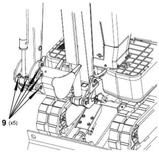
18.8 Checking the cooling fan
Caution
Always stop the engine before checking the cooling fan.
Caution
Wear eye protection when cleaning with compressed air.
- Check the cooling fan for normal operation more frequently in warm weather. Check for dust on the cooling fan of the petrol engine cylinder head. Please clean large accumulations of dust with compressed air.
- Check whether the exhaust silencer and the cladding are oxidised. Check whether the insulation layer of the exhaust silencer cladding is complete.
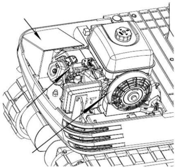
natural_image
Technical line drawing of a mechanical engine assembly (no text or symbols visible)Important!
The cooling fan must be clean so that the engine does not overheat and free ventilation of the system is possible.
18.9 Cleaning the engine and electrical cables
Caution
Always stop the engine before cleaning the cabling, lines and engine.
Before starting the engine, check whether flammable substances have accumulated on the battery, the cables and lines, the exhaust silencer or the engine. Remove these thoroughly.
18.10 Testing the electrical circuit
Check the electrical circuit for loose connections, short circuits or loosened connections.
18.11 Washing the whole machine
Important!
Do not wash the excavator with the engine running. Water could penetrate the air filter and damage the engine. Make sure that the air filter remains dry.
18.12 Regular checks and maintenance work
Every 50 operating hours:
18.12.1 Change the engine oil
Caution
First switch off the engine and wait until the oil has cooled down.
- Remove the drain plug from the underside of the engine and drain the oil completely.
Important!
Place a suitable container under the engine to collect the used oil. Dispose of used engine oil in accordance with local legislation. We recommend taking it to your local recycling centre or petrol station in a sealed container for recycling.
- Retighten the drain plug.
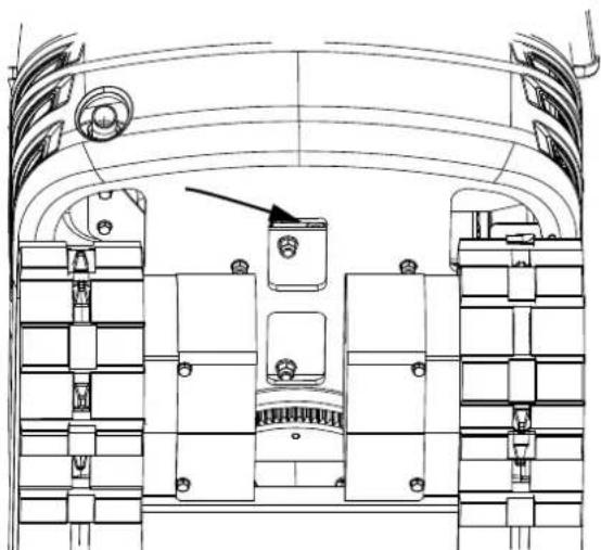
natural_image
Technical line drawing of a mechanical assembly with no visible text or symbols- Fill with new oil to the required level.
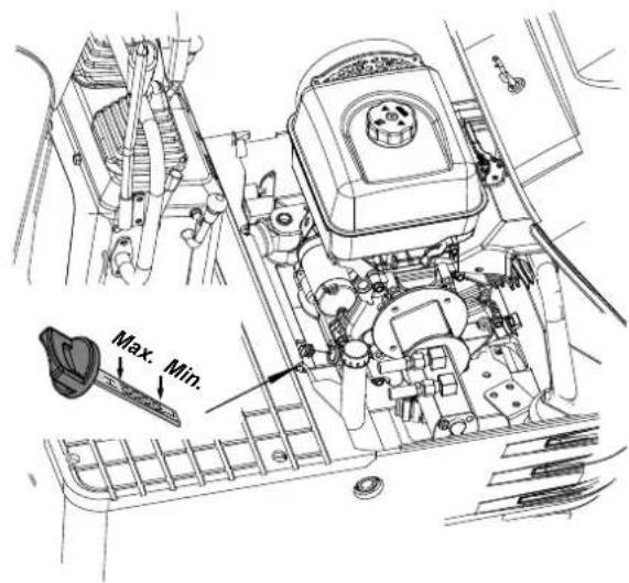
- Allow the engine to turn at idle speed for 5 minutes. Check the oil level. To do this, insert the dipstick fully into the opening provided and pull it out again. If the oil level is between the two markings, no oil needs to be topped up.
Important!
The engine oil must be changed once a year regardless of the operating hours.
Engine oil quantity 1.1 litre
Engine oil capacity:
306cc - 32 oz. (1.1 litres)

Note: The total oil quantity should be 4 more ounces (approx. 0.1 litres) above the above quantities due to the mounting angle and proper draining.
Note
If the engine is running with a low oil level, this can lead to engine damage.
Engine oil recommendations
The engine oil influences performance and service life. Use a 4-stroke automotive detergent oil.
SAE 10W-30 is recommended for general use.
Other viscosities shown in the diagram can be used if the average temperature in your area permits.
The SAE oil viscosity and the utilisation classification can be found on the API label on the oil container.
Use API SERVICE category SJ or higher engine oil.

bar
| Category | Value | |---|---| | 5W-30 | -20 | | 10W-30 | -10 | | 30 | 60 | The chart displays a single bar for each category, with the x-axis ranging from -30 to 100°F and the y-axis labeled as 'F'. The arrows indicate direction or magnitude between them.18.12.2 Battery maintenance
Caution
Batteries contain sulphuric acid, which can cause severe burns. Avoid contact with skin, eyes or clothing. First aid - External: Rinse with plenty of water. Internal: Drink large quantities of water or milk. Call a doctor immediately. Eyes: Rinse with plenty of water for 15 minutes and seek medical attention immediately. Keep batteries out of the reach of children.
Caution
Before inspecting or removing the battery, switch off the engine and set the ignition switch to the "OFF" position.
Caution
When removing the battery, always remove the negative earth cable first. When installing a battery, always connect the earthing cable last. This prevents a possible explosion due to sparking.
Caution
Always wear eye protection when working with the battery.
-
Check whether the battery appears deformed.
-
Replace the battery if it is deformed.
-
Remove any dust from the battery cover (ventilation opening).
-
Check whether the battery connections are loose. Tighten them if they are loose. Make sure that you tighten the positive screw and ensure that the tool used does not touch the cladding.
⚠ Warning!
Before tightening the positive screw, make sure that you switch off the switch of the negative earthing cable first.

18.12.3 Battery charged
Caution
When the battery has been activated, hydrogen and oxygen gases in the battery are extremely explosive. Keep open sparks and flames away from the battery at all times, especially when charging the battery.
Caution
When disconnecting the cable from the battery, start with the negative connection. When connecting the cable to the battery, start with the positive connection.
Caution
Do not check the charge status of the battery by placing a metal object over the connections.
-
To charge the battery slowly, connect the positive terminal of the battery to the positive charging connection and the negative terminal to the negative connection. Then charge as usual.
-
Fast charging should only be carried out in emergencies. The battery is then partially charged at high speed and in a short time. If you are using a fast-charging battery, the battery must be recharged as quickly as possible. If this is not done, it can shorten the service life of the battery.
-
Use a battery with the same specifications when replacing an old battery with a new one.
18.12.4 Lubricating the teeth of the swivel bearing
- Fill grease through the grease nipples (on the right-hand side).
- Lubricate at every 90° degree position (1.58 wheel) of the swivel frame.
- Fill with approx. 50 g grease (approx. 20 strokes with the grease gun). Spread the grease over the teeth.

natural_image
Technical line drawing of a mechanical assembly with no visible text or symbols18.12.5 Inspection and cleaning of the air filter element
- Open the bonnet and remove the dust cover.
- Remove the outer element, clean the element and the inside of the housing and reassemble.
- When reassembling, ensure that the dust cover is fitted with the UP mark (arrow) pointing upwards. Do not remove the inner element.
Important!
If the machine is used in extremely dusty areas, the air filter element must be inspected and cleaned more frequently than the specified maintenance intervals.
Important!
The air filter has a dry element, keep it free of oil.
Important!
Do not run the engine without the air filter.

natural_image
Technical line drawing of a tracked vehicle with a rectangular component and a side-mounted fan (no text or symbols)18.12.6 Maintenance of the air filter
Caution
Wear eye protection!

natural_image
Silhouette of a human head with motion arrows indicating sound or motion (no text or symbols)Cleaning with compressed air
The pressure of the compressed air must be below 205 kPa (2.1 kg/cm) and the cartridge must be blown clean from the inside to the outside until the dust deposits have been completely removed.

natural_image
Illustration of a hand using a tool to mark a surface with a small mark (no text or symbols present)Important!
If the air intake is still not sufficient or the colour of the exhaust gases is abnormal even after cleaning, the air filter element must be replaced.
18.12.7 Checking the spark plug
Use the special spark plug spanner to remove the spark plug and check whether there are any carbon deposits on the spark plug needle. In this case, remove the carbon deposits. Replace the spark plug if it is defective.

18.12.8 Maintenance of the spark plug
- E6TC (Torch) and E6RTC (Torch) are only used for 79cc and 98cc engines.
- F6TC, F6RTC or F6RTP spark plugs (torch) are recommended.
Cross-references:
- The designation of the Champion spark plug is: RN9YC (some tables show RN9YCC)
• The designation of the NGK spark plug is: BPR6ES
• The designation of the BOSCH spark plug is: WR6DC
Caution
Using the wrong spark plug can damage the engine.
- Remove the spark plug connector and use compressed air to remove deposits from the spark plug area.
-
Remove the spark plug with a 13/16-inch spark plug spanner.
-
Examine the spark plug. Replace them if the electrodes are worn or the insulation is torn or chipped. The spark plug gap should be set to 0.027 - 0.030 inch.
- Install the spark plug carefully to avoid wedging the threads. Screw the spark plug in by hand until it stops turning.
- Tighten the spark plug with a 13/16-inch spark plug spanner. Tighten the spark plug with a 1/4 turn when the spark plug is seated.
Caution
A loose spark plug can overheat and damage the engine. Overtightening the spark plug can damage the thread in the cylinder head.
- Refit the spark plug connector. Ensure that it engages securely.
Every 100 operating hours:
Carry out the complete 50 operating hours maintenance at the same time.
18.12.9 Lubricating the swivel bearing
- Lubricate through the corresponding grease nipples.
- Lubricate at every 90° position (1.58 wheel) of the swivel frame.
- Apply 5 strokes with the grease gun at each point.
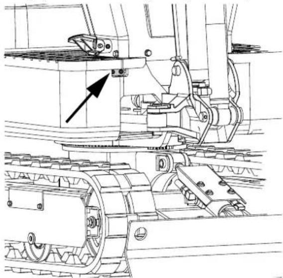
natural_image
Technical line drawing of a mechanical assembly with gears and linkages (no text or symbols)Every 200 operating hours:
Carry out the complete 50 and 100 operating hour maintenance at the same time.
18.12.10 Replacing the air filter element
Open the bonnet and remove the dust cover. Remove the outer and inner elements and replace them with new elements. When reassembling, make sure that you fit the dust cover with the UP mark (arrow) pointing upwards.

natural_image
Technical line drawing of a vehicle chassis with a grid panel and mechanical components (no text or symbols)Important!
Shorten the replacement intervals if you work in areas with a lot of dust or sand.
18.12.11 Checking the petrol line
- Check that all lines and hose clamps are secure and undamaged.
- If the lines and hose clamps are worn or damaged, they must be repaired or replaced immediately.
Every 1000 operating hours:
Carry out the complete 50, 100, 200 and 500 operating hour maintenance at the same time.
Changing the hydraulic oil (including replacing the suction filter and the return filter in the hydraulic tank)

natural_image
Technical line drawing of a mechanical assembly with no visible text or symbols
natural_image
Technical line drawing of a tracked vehicle showing internal components and motion arrows (no text or symbols)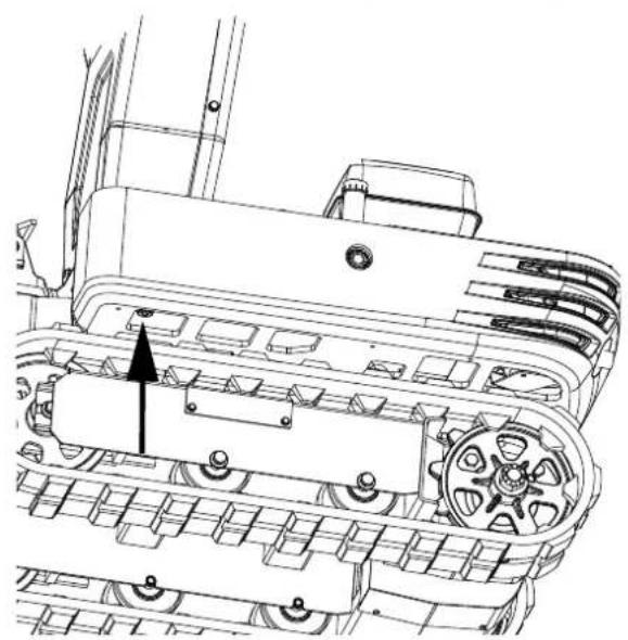
natural_image
Technical line drawing of a tracked vehicle with visible tracks, gears, and a central gear mechanism (no text or symbols)Check the level of the hydraulic oil in the inspection window. Add oil when the level is lower than 1/3.
| Hydraulic oil quantities | Hydraulic oil tank | approximately 10.8 litres |
| Total oil quantity | approximately 14.0 litres |
18.12.12 Hydraulic oil check
- Changing and topping up hydraulic oil (1) Only use the oil types recommended in the operator's manual to change or top up the oil.
- Do not mix different brands of oil when topping up.
- Change the return filter and oil.
- The filter must be changed more frequently due to contamination caused by frequent removal and attachment of the pipes.
- Use the correct filter for replacement.
- Oil change after operating hours.
| Return filter Suction filter | ||
| Normal excavation work | Every 1000 hours | 1000 hours |
Annual maintenance:
18.12.13 Electrical cabling and fuses
Check the connections regularly for correct connections. Loose cable connections or damaged cables can lead to malfunctions in the electrical system. This could lead to short circuits, leakage currents and other costly problems. Check the cabling and replace damaged components immediately. Contact your dealer if the fuse blows immediately after replacement. Only use the specified fuses.
18.12.14 Replacing the spark plug
Replace after one year or after 500 operating hours. Maintenance every two years.
18.12.15 Replacing the petrol line
Replace the cables and terminals. (See "Checking the petrol line" under Maintenance every 200 hours.)
18.13 Other settings and replacements
18.13.1 Adjusting the crawlers
Proceed as follows to loosen the crawlers:
Caution
Do not crawl under the excavator.
- Remove the side cover plate and loosen the M20 nut on the inside using a 30 mm spanner.
- Adjust the M20x120 hexagonal screw and turn it clockwise to tighten the crawler. The crawler loosens when you turn it clockwise.
- Tighten the M20 nut with a spanner after adjustment.
When tightening, the torque must be between 98 and 108 Nm. - Attach the side cover plate.
Note
Important!
If the crawlers are too tight, this increases wear.
Important!
If the crawlers are too loose, the crawler shoes can collide with the sprocket and wear is increased. The crawlers can shift and detach.
Important!
Clean the crawlers after each use.
Important!
If the tension of the crawlers is increased by adhering sludge, lift the crawlers using the boom, arm and bucket, allow the engine to turn at idle speed and carefully remove the sludge from the crawlers, especially the openings of the connecting plate.
Tension the crawlers as specified:

- Tension the crawlers when they are raised until the distance (clearance between the crawler roller and the inner surface of the crawlers) is 10 to 15 mm (see figure). In this case, the connecting piece of the crawlers is positioned at the top centre between the idle roller and the pinion.
Danger!
Do not work under the machine under these conditions.
Danger!
For safety reasons, do not rely on hydraulic stabilisers, as they can leak, drop suddenly or be lowered unintentionally.

natural_image
Technical line drawing of an excavator with attached levers and tracks (no text or symbols)
Ensure that no foreign objects such as stones get caught in the crawlers. Remove such foreign objects before adjusting the crawler tension.
Important!
Crawler connecting piece
The ends of the rubber crawlers are joined together with a connecting piece. When setting the crawlers, the connecting piece must be positioned at the top centre between the idle roller and the pinion. If the connecting piece is positioned incorrectly, the crawler will be tensioned too loosely and further readjustment will be necessary.
Important!
After adjusting, turn the crawler once or twice to check the tension.
Important!
In addition, the following points must be observed when adjusting the crawlers. (1) If a crawler sags more than 0.98 inches (25 mm), it must be readjusted. (2) Check the tension of the crawlers 30 hours after first use and readjust if necessary. Check and then adjust every 50 operating hours.
Special instructions for the use of rubber crawlers
- Change direction as slowly as possible. Avoid turning on the spot to prevent wear and the ingress of dirt.
- Move the machine a short distance straight backwards if too much dirt and sand is blocking the crawlers. The soil and sand will then fall out and you can change direction.
- Avoid using the rubber crawlers on riverbeds, stony surfaces, reinforced concrete and iron plates. The rubber can be damaged and wear increased.
18.14 Replacing the bucket
Caution
If the coupling pins are removed or installed, chips may fall off. Always use gloves, safety goggles and a helmet.
Caution
Always work in pairs if the device needs to be changed while the engine is running. One person sits in the operator's seat and the other works on the machine.
Caution
Do not use your fingers to centre the openings. These could be injured or severed by sudden, uncontrolled movements.
Caution
Read the manual for the attachment part in order to carry out an operation correctly and safely when installing other attachments.
18.15 Replacing fuses
A slow-blow fuse is provided to protect the electrical circuits. Check the electrical circuits for problems and replace the old one with a new, compatible slow-blow fuse if it has blown.
- Remove the cover from the fuse box.
- Replace the blown fuse with a new fuse of the same rating.
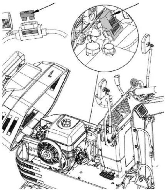
natural_image
Technical line drawing of an engine compartment with internal components and a magnified inset showing mechanical assembly (no text or labels)
natural_image
Technical line drawing of a mechanical assembly with internal components and a close-up inset showing a component detail (no text or symbols present)Performance of the fuse and circuits
| No. Power Switching circuit | |
| 1 10 A | Working relay fuse |
| 2 10 A | Fuse, work light, horn, hour meter |
18.16 Regular replacement of important components
To ensure safe operation, we strongly advise you to inspect and maintain the machine at regular intervals. For additional safety, ask your dealer to replace the following important components.
These parts are subject to material deterioration or wear out over time. During regular inspections, it is difficult to assess how badly they are damaged. They must therefore be replaced with new parts, even if the wear and tear is not visible after a certain period of use.
If a component is worn out before the end of its service life, it must be repaired or replaced in the same way as other parts.
If a hose clamp is deformed or torn, it must be repaired.
Check the following points for hydraulic lines that are not replaced regularly. Tighten or replace them if you notice any abnormalities.
When replacing the hydraulic lines, also replace their O-rings and seals. Contact your dealer to replace important parts.
Also check the petrol and hydraulic lines during the following regular inspections.
| Inspection interval | Control points |
| Daily checks Leaking | oil at the connections and points of petrol and hydraulic lines. |
| Monthly Leaking oil | at the connections and points of petrol and hydraulic lines. Damage to petrol and hydraulic lines (cracks, chafing). |
| Annually Leaking oil | at the connections and points of petrol and hydraulic lines. Impairment, deformation, deterioration, twisting and other damage (cracks, chafing) to petrol and hydraulic lines. |
List of important components
| No. Components | Place of use Quantity | Period | ||
| 1 Hydraulic line | (in-take) | Main pump 1 | Every 2 years or 4000 hours | |
| 2 Hydraulic line | (sup-ply) | Main pump control valve 2 | ||
| 3 Hydraulic line | (boom cylinder) | Control valve boom cylinder | 2 | |
| 4 Hydraulic line | (arm cylinder) | Control valve arm cylin-der | 2 | |
| 5 Hydraulic line | (buck-et cylinder) | Control valve bucket cylinder | 2 | |
| 6 Hydraulic line | (swiv-elling cylinder) | Control valve swivelling cylinder | 2 | |
| 7 Hydraulic conduit | (levelling blade cylinder & crawler cylinder) | Control valve swivel joint 4 | ||
| Levelling blade cylinder swivel joint | 4 | |||
| Swivel joint tank cylinder 2 | ||||
| 8 Hydraulic line | Control valve connection | 1 | ||
| Connection return line | 1 | |||
| 9 Hydraulic line | (swiv-elling motor) | Control valve swivel motor | 2 |
Only use a hydraulic line approved by the dealer to avoid serious damage to the hydraulic system.
18.17 Recommended oil types
Fuel recommendations
Use unleaded petrol with an octane rating of 86 or higher. These engines work best with unleaded petrol. NEVER use stale or contaminated petrol or an oil/petrol mixture. Prevent dirt or water from getting into the petrol tank. Only use suitable and properly labelled petrol cans. Maximum recommended ethanol content: 10% This is not compatible with E15.
Engine oil recommendations
The engine oil influences performance and service life. Use 4-stroke automotive oil. SAE 10W-30 is recommended for general use. Other viscosities shown in the diagram can be used if the average temperature in your area permits.

bar
| Range | Value (F) | |---|---| | 30 | 60 | | 10W-30 | -20 | | 5W-30 | -10 |Recommended hydraulic oils
Important!
A hydraulic oil of ISO 32 quality was used before delivery.
Recommended hydraulic oil type:
10W AW32
ASLE H-150
ISO 32
Recommended lubricating oil
| Usage Shell | Mobil Exxon | ||
| Lubrication | Shell Alvania EP2 | Mobilux EP2 | Beacon Q2 |
The SAE oil viscosity and the utilisation classification can be found on the API label on the oil container. Use API SERVICE category SJ or higher engine oil.
19. Repair & ordering spare parts
After repairs or maintenance, make sure that all safety-related parts are installed and are in perfect condition. All parts which may cause injury must be kept where they are inaccessible to children or others.
Attention: According to the German Product Liability Act, no liability is accepted for damage caused by improper repairs or by not using original spare parts. Such work should be performed by a customer service centre or an authorised specialist. The same applies to accessory parts.
Spare parts and accessories can be obtained from our Service Centre. To do this, scan the QR code on the front page.
Connections and repairs
Connections and repair work on the electrical equipment may only be carried out by electricians.
Please provide the following information in the event of any queries:
• Type of current for the motor
• Machine data - type plate
- Motor data - type plate
Important note in the case of repairs:
For return delivery of the product for repair, please ensure for safety reasons that it is free of oil and fuel when it is sent to the service centre.
19.1 Ordering spare parts
Please provide the following information when ordering spare parts:
- Model designation
- Item number
- Type plate data
Spare parts / accessories Article no.:
Excavator roof 7915001704
Excavator thumb 7915001701
Excavator rake 7915001705
Excavator shovel 7915001703
Retaining claw 7915001702
19.2 Service information
With this product, it is necessary to note that the following parts are subject to natural or usage-related wear, or that the following parts are required as consumables.
Wearing parts*: V-belt, engine oil, spark plug, air filter, rubber tracks
* may not be included in the scope of delivery!
20. Disposal and recycling
Notes for packaging


The packaging materials are recyclable. Please dispose of packaging in an environmentally friendly manner.
Information on the battery act [BattG]
![SCHEPPACH EXC815 - Information on the battery act [BattG] - 1](/content/2026/03/523653/images/9fb88cb2352e7d20e134e294c6827c6736d2d07e7b7e989b0a2655bbe8400bc9.jpg)
Old batteries and rechargeable batteries do not belong in household waste, but must be collected or disposed of separately!
- For safe removal of batteries or rechargeable batteries from the electrical device and for information on their type or chemical system, please refer to the additional information in the operating or assembly instructions.
- Owners or users of batteries and rechargeable batteries are legally obliged to return them after use. The return is limited to household quantities.
- Old batteries may contain pollutants or heavy metals that can harm the environment or human health. Recycling old batteries and using the resources they contain helps to protect these two important issues.
- The symbol of the crossed-out dustbin means that batteries and rechargeable batteries must not be disposed of with household waste.
-
If the signs Hg, Cd or Pb are also located below the dustbin symbol, this stands for the following:
-
Hg: Battery contains more than 0.0005% mercury
- Cd: Battery contains more than 0.002% cadmium
- Pb: Battery contains more than 0.004% lead
- Rechargeable batteries and batteries can be returned free of charge to the following places:
- Public disposal or collection points (e.g. municipal works yards)
- Sales points for batteries and rechargeable batteries
- Take-back points of the common take-back system for old device batteries
- Take-back point of the manufacturer (if not a member of the common take-back system)
- These statements are only valid for rechargeable batteries and batteries sold in the countries of the European Union and subject to the European Directive 2006/66/EC. In countries outside the European Union, different regulations may apply to the disposal of rechargeable batteries and batteries.
You can find out how to dispose of the disused device from your local authority or city administration.
Fuels and oils
- Before disposing of the device, the fuel tank and the motor oil tank must be emptied!
- Fuel and engine oil do not belong in household waste or drains, but must be collected or disposed of separately!
- Empty oil and fuel tanks must be disposed of in an environmentally friendly manner.
21. Troubleshooting
The following table shows fault symptoms and describes remedial measures in the event of your product failing to work properly. If you cannot localise and rectify the problem with this, please contact your service workshop.
| Fault Possible cause Remedy | |||
| Engine | Starting difficulties | The petrol valve is shut. | Ensure that the petrol valve is in the “Open” position. |
| Air or water in the fuel system. | See the instructions in the section “Removing water or air from the petrol tank” to remove air and water. | ||
| The viscosity of the oil is too high, so that the engine turns too slowly in winter. | Use winter hydraulic oil. | ||
| The battery is almost flat. The starter motor does not work. | Start with the cable pull to recharge the battery. | ||
| The spark plug does not ignite. | Replace the spark plug. | ||
| Low oil level. Add engine oil. | |||
| Insufficient engine power. | Low fuel level. Check the fuel level and top up if necessary. | ||
| Air filter blocked. Clean the air filter element. | |||
| The engine suddenly stops. | Low fuel level. | Check the fuel level and top up if necessary. Flush the fuel system. | |
| Abnormal colour of the exhaust gases. | Bad petrol. Use high quality petrol. | ||
| Too much engine oil. Drain the engine oil to the specified oil quantity. | |||
| The cold starter lever shuts the cold starter valve in the carburettor. | Open the cold starter valve. | ||
| Hydraulic system | The performance of the boom, arm, bucket, drive, swivelling function and levelling blade is too poor. | Too little hydraulic oil. Add oil. | |
| Leaks in lines and/or connections. | Replace the line or connection. | ||
| The swivel motor does not work. | The swivelling locking pin is in the locking position. | Remove the swivelling locking pin from the locking position. | |
| Drive system | Deviation from the direction of travel. | Blockage by stones. Remove the foreign objects. | |
| The crawlers are too loose or too tight. | Set the appropriate settings. | ||
Lifting capacity
-
The lifting capacity is based on ISO 10567 and does not exceed 75% of the static tipping load of the machine or 87% of the hydraulic lifting capacity of the machine.
-
The strokes are as follows:
• The load point corresponds to the front bolt part of the arm.
• The machine positions are (i) over front (top plate), (ii) over front (bottom plate), and (iii) over side.
• The working cylinder is the boom cylinder.
- The excavator bucket, hook, loop and other lifting accessories are included in the loads.
Machine states:
No bucket, all others according to standard regulations.
Warning!
It is not permitted to lift loads greater than those listed in the lifting capacity tables.
Warning!
The values specified in the tables only apply on a level, hard surface. When lifting on soft ground, the machine can tip over because the load is only concentrated on one part of the machine. The table values are calculated at the end of the arm without the bucket. To find the permitted loads for machines with a bucket, the weight of the bucket must be taken off the values in the table.
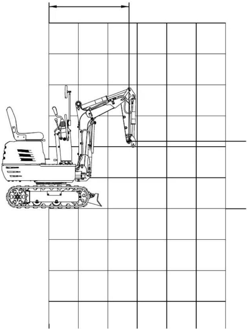
natural_image
Technical line drawing of an excavator with tracked vehicle, shown in top and side views (no text or labels)
(i) OVER FRONT (TOP PLATE) kN(kg)
| Height (mm) Load radius (mm) | |||||||
| 0 380 76 | 0 1140 1520 | 1900 2280 | |||||
| 2400 | |||||||
| 2000 | |||||||
| 1600 1.1 (110) | |||||||
| 1200 1.1 (110) | |||||||
| 800 1.7 (170) | 1.1 (110) | 0.8 (80) | |||||
| 400 1.7 (170) | 1.1 (110) | 0.8 (80) | |||||
| 0 | 1.7 (170) | 1.1 (110) | |||||
| 400 | 3.2 (320) | 1.7 (170) | 1.1 (110) | ||||
| 800 1.3 (130) | |||||||
| 1200 | |||||||
(i) OVER FRONT (BOTTOM PLATE)
kN(kg)
| Height (mm) Load radius (mm) | |||||||
| 0 | 380 760 11 | 40 1520 1900 | 2280 | ||||
| 2400 | |||||||
| 2000 | |||||||
| 1600 | 1.4 (140) | ||||||
| 1200 | 1.4 (140) | ||||||
| 800 | 2.2 (220) | 1.6 (160) | 1.4 (140) | ||||
| 400 | 3.0 (300) | 1.9 (190) | 1.5 (150) | ||||
| 0 | 3.1 (310) | 2.0 (200) | |||||
| 400 | 3.2 (320) | 2.7 (270) | 1.7 (170) | ||||
| 800 | 1.3 (130) | ||||||
| 1200 | |||||||
ATTACHMENTS (AVAILABLE SEPARATELY)
Excavator rake 7915001705 (AVAILABLE SEPARATELY)
The hoe is attached to the end of the bucket and is ideal for raking straw, sieving rocks or levelling the ground.
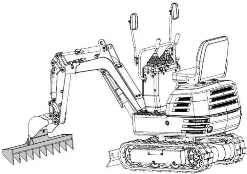
natural_image
Technical line drawing of an excavator with tracked blade and bucket (no text or symbols)Assembly
Stop the machine and lift the bucket to a certain height above the ground. Remove the M12x40 bolts, washers and nuts pre-assembled on the hoe. Attach the hoe to the bucket using these standard parts.

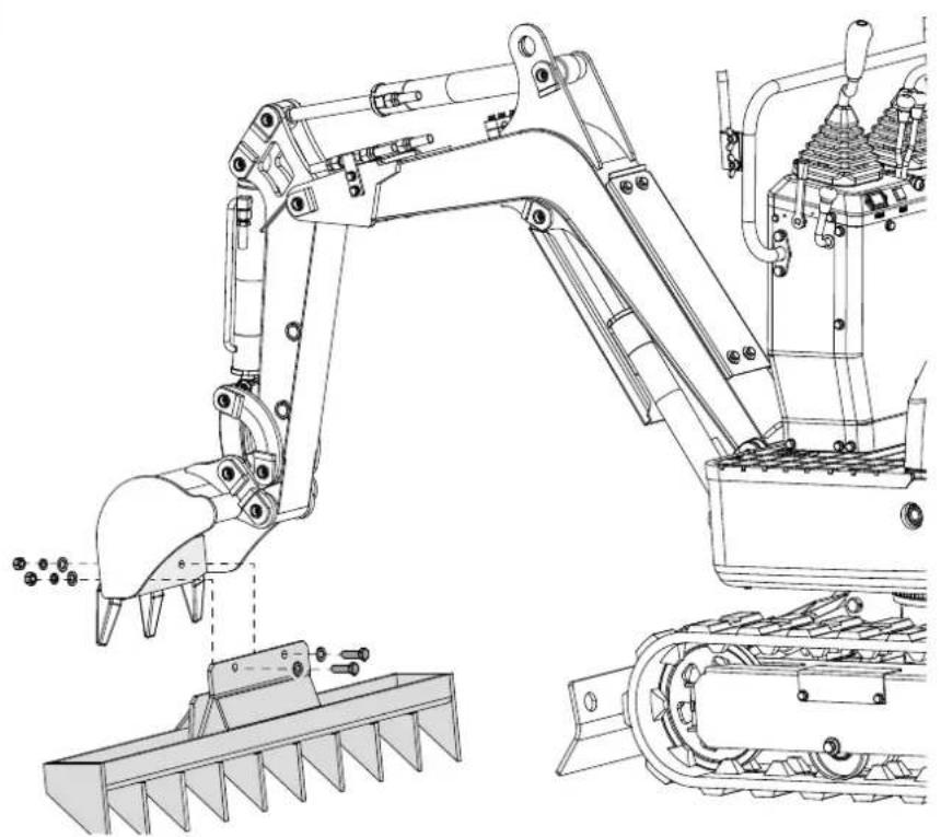
natural_image
Technical line drawing of an excavator assembly with blade and guide components (no text or labels)Excavator thumb 7915001701 (AVAILABLE SEPARATELY)
The thumb gripper can hold materials in place in the bucket. It can be used together with the bucket to grab regularly or irregularly shaped materials, for example rocks, wood or building rubble.

natural_image
Line drawing of an excavator with attached mechanical components (no text or symbols)Assembly
Remove the 20x120 pins, washers and R-pins from the thumb grip holder. Attach the bracket to the arm and align the openings. Insert two shaft pins through the openings, fit the washers and secure the connection with R-pins. Insert the larger end of the thumb grip into the holder, align the openings and secure with the two other pins, washers and R-pins.

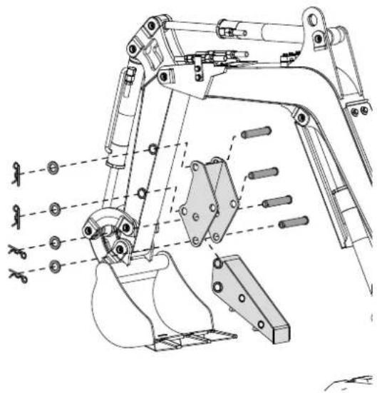
natural_image
Technical line drawing of an excavator assembly with multiple components and alignment guides (no text or labels)Pull out the lower R-pin and the pin when the thumb grip is not in use. Fold the thumb grip into the holder and secure the upper position with the previously removed parts.

natural_image
Technical line drawings of an excavator assembly showing three sequential stages of tool movement (no text or labels)Excavator claw 7915001702 (AVAILABLE SEPARATELY)
The ripper tooth can be used without a cover to collect leaves, gravel and straw. The complete ripper tooth with cover is ideal for materials with small particles such as sand and soil.

natural_image
Technical line drawing of an excavator with tracked base and control panel (no text or symbols)Fitting the ripper tooth
- Remove the 60x110 pins, washers and R-pins from the clamp. Install the clamp on the thumb, align the openings and fasten with the pins, washers and R-pins.


natural_image
Technical line drawing of an excavator assembly with levers and gears (no text or labels)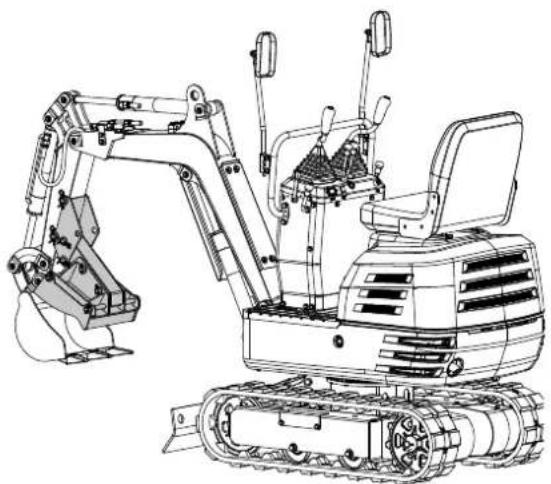
natural_image
Technical line drawing of an excavator with tracked base and attached levers (no text or symbols)- Remove the pins 16x300, the washers and the R-pins from the cover of the ripper tooth. Attach the cover to the clamp from the outside and align the openings. Insert two 16x300 pins through the openings, attach the washers and fasten with R-pins.

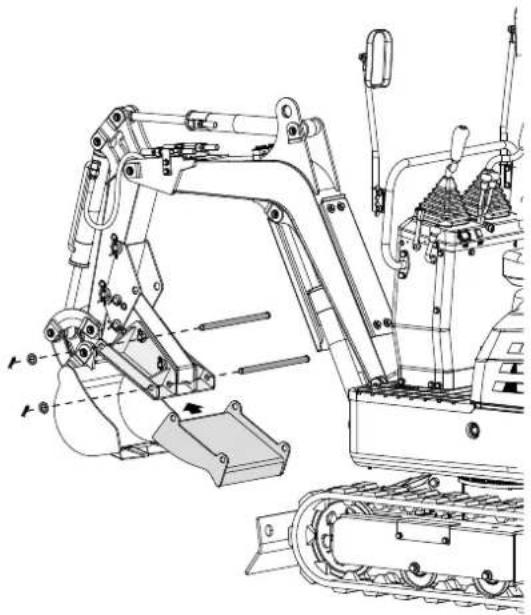
natural_image
Technical line drawing of an excavator assembly with levers and conveyor (no text or labels)Grading bucket 7915001703 (AVAILABLE SEPARATELY)
The grading bucket replaces the machine's standard bucket. With its larger capacity, it can double the working efficiency when digging loose material.

natural_image
Line drawing of an excavator with tracked base and blade assembly (no text or symbols)Assembly
Place the standard bucket on the ground and stop the machine. Remove the pins from the bolts and remove the standard bucket. Fit the grading bucket to the machine using the bolts removed in the first step.


natural_image
Technical line drawing of an excavator with levers and tracks (no text or symbols)Excavator canopy 7915001704 (AVAILABLE SEPARATELY)
The excavator canopy is connected to the platform of the swivelling unit. It is ideal for protection from sunlight, rain and other weather conditions. It is easy to fit and remove.

natural_image
Technical line drawing of an excavator with tracked base and attached boom (no text or symbols)Assembly
Align the holes in the lower frame of the excavator canopy with the holes in the platform of the swivelling unit as shown. Attach the lower frame using the M10x60 screws and washers supplied.
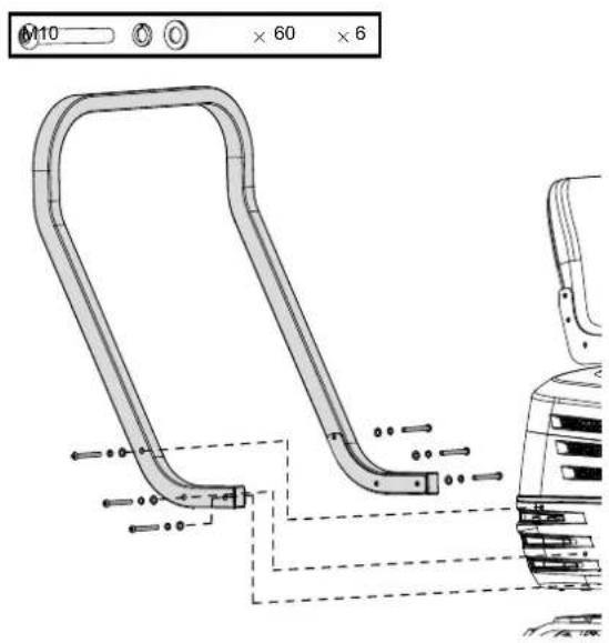
Align the holes in the upper frame with the holes in the lower frame of the excavator canopy as shown. Secure the connection with the M10x95 screws, washers and nuts supplied.

Align the holes in the upper part of the canopy with the holes in the upper frame of the excavator canopy as shown. Fasten the canopy top using the M8x25 screws, washers and nuts supplied.
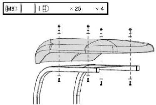
Günzburger Straße 69
D-89335 Ichenhausen
Cher client,
9. Montage
natural_image
Technical line drawing of a vehicle seat assembly showing front and side views (no text or symbols)Avertissement !
natural_image
Line drawing of an excavator performing maintenance on a utility pole (no text or symbols present)natural_image
Technical line drawing of an excavator with a mounted arm and levers (no text or symbols)natural_image
Technical diagram of a mechanical assembly with no visible text or symbolsnatural_image
Technical line drawing of a mechanical assembly with two lock icons and a curved component (no text or symbols)natural_image
Technical line drawing of a vehicle chassis assembly (no text or symbols)natural_image
Technical line drawing of a mechanical device with labeled components and a battery symbol (no readable text or symbols)natural_image
Technical line drawing of a mechanical device with no visible text or symbolsRemarque :
natural_image
Technical diagram of a mechanical assembly with no visible text or symbolsnatural_image
Technical line drawing of a mechanical assembly with no visible text or symbolsnatural_image
Technical line drawings of mechanical components, including a crane arm and excavator assembly (no text or labels)⚠ Attention
natural_image
Technical line drawing of a mechanical assembly with no visible text or symbolsnatural_image
Technical line drawing of an excavator assembly with pump and bucket components (no text or labels)12.7 Pivotement
Attention
natural_image
Technical diagram of a mechanical or electrical component with pipes and gauges, no visible text or symbols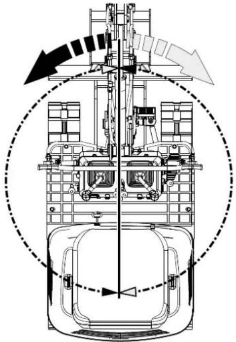
natural_image
Technical line drawing of a mechanical assembly with no visible text or symbolsnatural_image
Technical line drawing of a mechanical assembly with no visible text or symbols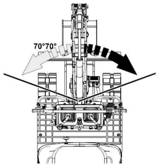
natural_image
Technical line drawing of a mechanical assembly with no visible text or symbolsnatural_image
Technical diagram of a mechanical or electrical component with no visible text, numbers, or symbols.
natural_image
Mechanical assembly diagram showing a conveyor belt system with directional arrows indicating motion (no text or labels)natural_image
Mechanical assembly diagram showing a conveyor belt system with a directional arrow (no text or labels)natural_image
Technical diagram of a mechanical or electrical device with no visible text, numbers, or symbols.

natural_image
Mechanical assembly diagram showing a central rotating component with multiple wheels and directional arrows indicating motion (no text or labels)natural_image
Technical line drawing of an excavator with downward load arrows, no text or symbols presentImportant!
natural_image
Illustration of two excavators on a slope, one with an upward arrow and the other with an arrow (no text or symbols)Important!
natural_image
Illustration of a bulldozer with a cross symbol crossed out, indicating no movement or restriction (no text or symbols present)12.12 Changement de direction
Prudence
natural_image
Diagram showing a car interior with upward arrows and a mechanical component (no text or symbols)natural_image
Diagram showing a mechanical device with a downward arrow and a right-side view of its internal structure (no text or symbols)natural_image
Diagram showing a device with internal components and a mechanical assembly with a circular component (no text or symbols)natural_image
Diagram showing a vehicle battery connected to a mechanical component with directional arrows indicating flow or movement (no text or symbols present)flowchart
graph TD
    A["Device with two circular components"] --> B["Assembly Step 1"]
    B --> C["Assembly Step 2"]
    C --> D["Assembly Step 3"]
    D --> E["Assembly Step 4"]
natural_image
Line drawing of an excavator on a tracked ground surface, showing motion direction (no text or symbols)12.18 Se garer en pente
⚠ Avertissement !
natural_image
Technical line drawing of an excavator on a sloped terrain (no text or symbols)natural_image
Technical line drawing of an excavator with tracked arm and attached platform (no text or symbols)
natural_image
Technical diagram of a mechanical assembly with no visible text or symbols
natural_image
Technical diagram of a mechanical assembly with no visible text or symbols
natural_image
Simple line drawing of a dump truck with an excavator and wheels, no text or symbols presentnatural_image
Line drawing of a construction vehicle with an excavator on an inclined ramp (no text or symbols)Danger!
natural_image
Illustration of a person using a dump truck to lift or stand, with two upward arrows indicating load or damage (no text or symbols present)natural_image
Line drawing of a construction vehicle with an excavator on its side (no text or symbols)natural_image
Technical line drawing of a vehicle interior showing lock mechanism and door panel (no text or symbols)natural_image
Technical diagram of electrical insulator components with lock symbols and tubing (no text or labels)natural_image
Simple line drawing of a dump truck with an excavator and wheels, no text or symbols presentnatural_image
Technical line drawing of an excavator with labeled components (no text or symbols present)
natural_image
Technical line drawing of a mechanical assembly with rollers and clamps (no text or symbols)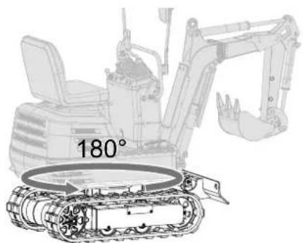
natural_image
Technical line drawing of an excavator with a 180° angle annotation (no other text or symbols)
17. Stockage
Prudence
natural_image
Silhouette of a hand holding a cylindrical object with motion arrows indicating movement (no text or symbols)natural_image
Silhouette of a human head with sunglasses and motion arrows, no text or symbols presentnatural_image
Technical line drawing of a truck engine bay with visible components and no text or symbolsnatural_image
Technical line drawing of a mechanical assembly with gears and levers (no text or symbols)natural_image
Technical line drawing of a mechanical assembly with an inset showing internal components (no text or symbols)natural_image
Technical line drawing of a mechanical assembly with no visible text or symbols8 (x2)
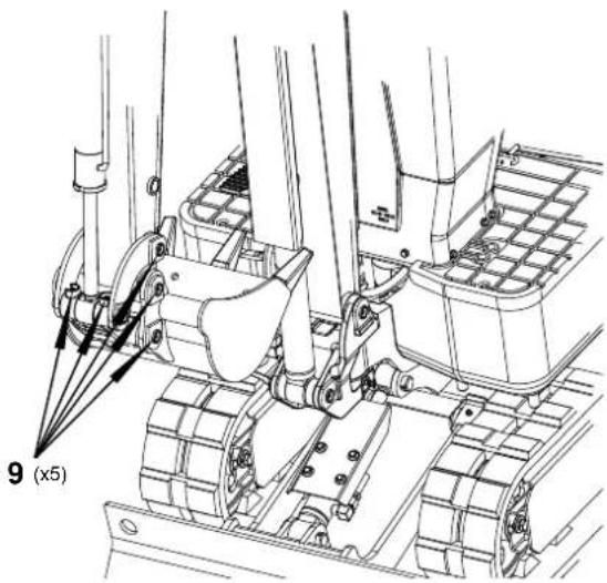
natural_image
Technical line drawing of a mechanical engine assembly (no text or symbols visible)natural_image
Technical line drawing of a mechanical assembly with no visible text or symbolsbar
| Range | Value | |---|---| | 5W-30 | -20 | | 10W-30 | -10 | | 30 | 60 | | Rightward Arrow (30) | 80 | | Rightward Arrow (10W-30) | 100 | | Leftward Arrow (5W-30) | -20 | | Bottom Right Arrow (5W-30) | -30 | The chart displays a horizontal bar for each range, with values increasing from left to right. The X-axis represents temperature in degrees Fahrenheit (F), and the Y-axis represents the numerical range of the range. The label '10W-30' appears near the middle of the bar.natural_image
Technical line drawing of a mechanical assembly with no visible text or symbolsnatural_image
Technical line drawing of a vehicle chassis with a grid panel and control panel (no text or symbols)natural_image
Silhouette of a human head with motion arrows indicating sound or motion (no text or symbols)natural_image
Illustration of a hand using a tool to mark a point on a gridded metal tray (no text or symbols)Important!
natural_image
Technical line drawing of a mechanical assembly with gears and linkages (no text or symbols)natural_image
Technical line drawing of a vehicle chassis with a grid panel and control panel (no text or symbols)Important!
natural_image
Technical line drawing of a mechanical assembly with no visible text or symbols
natural_image
Technical line drawing of a tracked vehicle showing internal components and motion arrows (no text or symbols)
natural_image
Technical line drawing of a tracked vehicle with visible tracks, gears, and a central component (no text or symbols)natural_image
Technical line drawing of an excavator with attached tracks and levers (no text or symbols)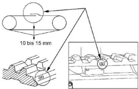
natural_image
Technical line drawing of an automotive engine bay with internal components and a magnified inset showing internal components (no text or labels)
natural_image
Technical line drawing of a mechanical assembly with internal components and a close-up inset showing a component detail (no text or symbols present)natural_image
Technical line drawing of an excavator with tracked vehicle, shown in top and side views (no text or labels)
(i) SUR L'AVANT (PANNEAU EN HAUT) kN(kg)
| Hauteur (mm) Rayon de charge (mm) | |||||||
| 0 380 76 | 0 1140 1520 | 1900 2280 | |||||
| 2400 | |||||||
| 2000 | |||||||
| 1600 1,1 (110) | |||||||
| 1200 1,1 (110) | |||||||
| 800 | 1,7 (170) | 1,1 (110) | 0,8 (80) | ||||
| 400 | 1,7 (170) | 1,1 (110) | 0,8 (80) | ||||
| 0 1,7 (170) 1,1 (110) | |||||||
| 400 | 3,2 (320) | 1,7 (170) | 1,1 (110) | ||||
| 800 | 1,3 (130) | ||||||
| 1200 | |||||||
(i) SUR L'AVANT (PANNEAU EN BAS)
kN(kg)
| Hauteur (mm) Rayon de charge (mm) | |||||||
| 0 | 380 760 11 | 40 1520 1900 | 2280 | ||||
| 2400 | |||||||
| 2000 | |||||||
| 1600 | 1,4 (140) | ||||||
| 1200 | 1,4 (140) | ||||||
| 800 | 2,2 (220) | 1,6 (160) | 1,4 (140) | ||||
| 400 | 3,0 (300) | 1,9 (190) | 1,5 (150) | ||||
| 0 | 3,1 (310) | 2,0 (200) | |||||
| 400 | 3,2 (320) | 2,7 (270) | 1,7 (170) | ||||
| 800 | 1,3 (130) | ||||||
| 1200 | |||||||
ACCESSOIRES (DISPONIBLES SÉPARÉMENT)
Godet râteau 7915001705 (DISPONIBLE SÉPARÉMENT)
natural_image
Technical line drawing of an excavator with tracked blade and bucket (no text or symbols)Montage
natural_image
Technical line drawing of an excavator arm and tracked vehicle (no text or symbols)Butée de pelle 7915001701 (DISPONIBLE SÉPARÉMENT)
natural_image
Line drawing of an excavator with attached mechanical components (no text or symbols)Montage
natural_image
Technical line drawing of an excavator arm assembly (no text or labels)Grappin à godet 7915001702 (DISPONIBLE SÉPARÉMENT)
natural_image
Line drawing of an excavator with tracked base and mechanical components (no text or symbols)natural_image
Technical line drawing of an excavator assembly with levers and tracks (no text or labels)
natural_image
Technical line drawing of an excavator with tracked base and control panel (no text or symbols)natural_image
Technical line drawing of an excavator assembly with levers and tracks (no text or labels)Godet de terrassement 7915001703 (DISPONIBLE SÉPARÉMENT)
natural_image
Line drawing of an excavator with tracked base and blade assembly (no text or symbols)Montage
natural_image
Technical line drawing of an excavator with tracked base and bucket assembly (no text or symbols)Arceau de protection 7915001704 (DISPONIBLE SÉPARÉMENT)
natural_image
Technical line drawing of an excavator with tracked base and attached boom (no text or symbols)Montage
Günzburger Straße 69
D-89335 Ichenhausen, Germania
Egregio cliente,
9. Montaggio
natural_image
Technical line drawing of a vehicle interior showing structural components and assembly (no text or symbols)Avviso!
natural_image
Line drawing of an excavator on a utility pole, showing mechanical arm and wiring (no text or symbols)natural_image
Technical line drawing of an excavator on a construction ground (no text or symbols)natural_image
Technical diagram of a mechanical assembly with no visible text or symbolsnatural_image
Technical line drawing of a mechanical assembly with two lock icons and a curved component (no text or symbols)10.2 Controlli quotidiani
natural_image
Technical line drawing of a vehicle chassis assembly (no text or labels)natural_image
Technical line drawing of a mechanical device with labeled components and an internal battery symbol (no text or labels present)natural_image
Technical line drawing of a mechanical device with no visible text or symbolsNota:
natural_image
Technical diagram of a mechanical assembly with no visible text or symbolsnatural_image
Technical line drawing of a mechanical assembly with no visible text or symbolsnatural_image
Technical line drawings of mechanical components, including a crane arm and excavator assembly (no text or labels)Attenzione
natural_image
Technical line drawing of a mechanical assembly with no visible text or symbolsnatural_image
Technical line drawings of industrial machinery components, including a pump and excavator assembly (no text or labels)natural_image
Technical diagram of a mechanical or electrical component with pipes and gauges, no visible text or symbols
natural_image
Technical line drawing of a mechanical assembly with no visible text or symbolsnatural_image
Technical line drawing of a mechanical assembly with no visible text or symbols
natural_image
Technical line drawing of a mechanical assembly with no visible text or symbolsnatural_image
Technical diagram of a mechanical assembly with pipes and components (no visible text or labels)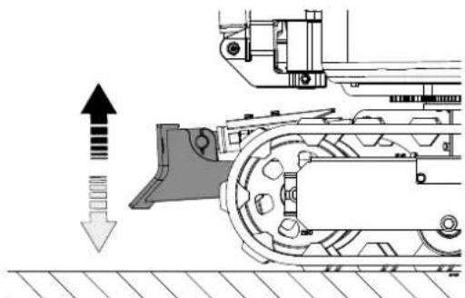
natural_image
Mechanical assembly diagram showing a conveyor belt system with directional arrows indicating motion (no text or labels)natural_image
Technical line drawing of a mechanical assembly with no visible text or symbolsnatural_image
Technical diagram of a mechanical or electrical device with no visible text, numbers, or symbols.

natural_image
Mechanical assembly diagram showing a central rotating component with multiple wheels and directional arrows (no text or labels)natural_image
Technical line drawing of an excavator with downward load arrows, no text or symbols presentImportante!
natural_image
Illustration of two excavators on a construction ground, showing different mechanical configurations (no text or symbols present)Importante!
natural_image
Illustration of a bulldozer with a black X symbol crossed out, indicating no movement or restriction (no text or symbols present)natural_image
Diagram showing a car interior with upward arrows and a mechanical component inside, no text or symbols present.natural_image
Diagram showing a mechanical device with a downward arrow and a right-hand view of a gear mechanism (no text or symbols)natural_image
Diagram showing airflow or mechanical components with no visible text or symbolsnatural_image
Diagram showing a vehicle battery with an upward arrow and a mechanical component inside, alongside its motion arrow (no text or symbols)flowchart
graph TD
    A["Device with two circular components"] --> B["Step 1: Downward motion"]
    B --> C["Step 2: Upward motion"]
    C --> D["Step 3: Rightward motion"]
    D --> E["Final assembled device with wheels and blocks"]
natural_image
Line drawing of an excavator on a construction ground, showing blade and support structure (no text or symbols)12.18 Parcheggio su un pendio
Avviso!
natural_image
Technical line drawing of an excavator on a sloped terrain (no text or symbols)natural_image
Technical line drawing of an excavator with tracked base and support structure (no text or symbols)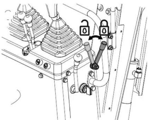
natural_image
Technical diagram of a mechanical assembly with no visible text or symbols
natural_image
Technical diagram of a mechanical assembly with no visible text or symbols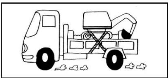
natural_image
Simple line drawing of a dump truck with an excavator and wheels, no text or symbols presentnatural_image
Line drawing of a construction vehicle with an excavator on an inclined plane (no text or symbols)Pericolo!
natural_image
Illustration of a construction worker kneeling beside a dump truck with arrows indicating upward forces (no text or symbols)natural_image
Line drawing of a construction vehicle with an excavator on its side, no text or symbols presentnatural_image
Technical line drawing of a mechanical device with lock symbols and a gear base (no text or labels)natural_image
Technical diagram of electrical insulator components with lock symbols (no text or labels)natural_image
Simple line drawing of a dump truck with an excavator and wheels, no text or symbols presentnatural_image
Technical line drawing of an excavator with labeled components (no text or symbols present)
natural_image
Technical line drawing of a mechanical assembly with rollers and clamps (no text or symbols)
natural_image
Technical line drawing of an excavator with a 180° angle annotation (no other text or symbols)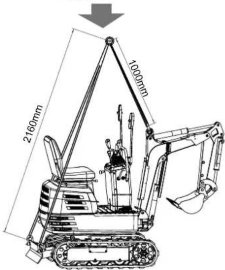
17. Stoccaggio
⚠️ Cautela
natural_image
Illustration of a hand holding a cylindrical object with motion arrows indicating movement (no text or symbols)natural_image
Silhouette of a human head with sunglasses and motion lines, no text or symbols present18.3 Controlli quotidiani
natural_image
Technical line drawing of a vehicle engine bay with visible components and structural details (no text or symbols)natural_image
Technical line drawing of a mechanical assembly with gears and levers (no text or symbols)natural_image
Technical line drawing of a mechanical assembly with an inset showing internal components (no text or symbols)natural_image
Technical line drawing of a mechanical assembly with no visible text or symbols8 (x2)

natural_image
Technical line drawing of a mechanical engine assembly (no text or symbols visible)Importante!
natural_image
Technical line drawing of a mechanical assembly with no visible text or symbolsnatural_image
Technical line drawing of a mechanical assembly with no visible text or symbolsnatural_image
Technical line drawing of a vehicle chassis with a grid-patterned component and an attached air conditioner unit (no text or symbols)natural_image
Silhouette of a human head with motion arrows indicating sound or motion (no text or symbols)natural_image
Line drawing of a hand using a tool to mark a small object on a grid-patterned surface (no text or symbols)Importante!
natural_image
Technical line drawing of a mechanical assembly with gears and levers (no text or symbols)natural_image
Technical line drawing of a vehicle chassis with a grid panel and control panel (no text or symbols)Importante!
natural_image
Technical line drawing of a mechanical assembly with no visible text or symbols
natural_image
Technical line drawing of a tracked vehicle showing internal components and motion arrows (no text or symbols)
natural_image
Technical line drawing of a tracked vehicle with visible tracks, gears, and a central gear mechanism (no text or symbols)natural_image
Technical line drawing of an excavator with tracked base and attached boom (no text or symbols)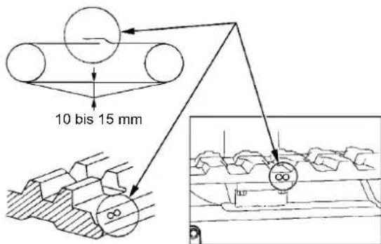
natural_image
Technical line drawing of an automotive engine bay with internal components and a magnified inset showing mechanical assembly (no text or symbols)
natural_image
Technical line drawing of a mechanical assembly with internal components and a close-up inset showing a component detail (no text or symbols present)natural_image
Technical line drawing of an excavator with tracked vehicle, shown in top and side views (no text or labels)
(i) SOPRA LA PARTE ANTERIORE (LAMA IN ALTO) kN(kg)
| Altezza (mm) Raggio di carico (mm) | |||||||
| 0 380 760 | 1140 1520 | 1900 2280 | |||||
| 2400 | |||||||
| 2000 | |||||||
| 1600 1,1 (110) | |||||||
| 1200 1,1 (110) | |||||||
| 800 1,7 (170) | 1,1 (110) | 0,8 (80) | |||||
| 400 1,7 (170) | 1,1 (110) | 0,8 (80) | |||||
| 0 | 1,7 (170) | 1,1 (110) | |||||
| 400 | 3,2 (320) | 1,7 (170) | 1,1 (110) | ||||
| 800 1,3 (130) | |||||||
| 1200 | |||||||
(i) SOPRA LA PARTE ANTERIORE (LAMA IN BASSO)
kN(kg)
| Altezza (mm) Raggio di carico (mm) | |||||||
| 0 | 380 760 11 | 40 1520 1900 | 2280 | ||||
| 2400 | |||||||
| 2000 | |||||||
| 1600 | 1,4 (140) | ||||||
| 1200 | 1,4 (140) | ||||||
| 800 | 2,2 (220) | 1,6 (160) | 1,4 (140) | ||||
| 400 | 3,0 (300) | 1,9 (190) | 1,5 (150) | ||||
| 0 | 3,1 (310) | 2,0 (200) | |||||
| 400 | 3,2 (320) | 2,7 (270) | 1,7 (170) | ||||
| 800 | 1,3 (130) | ||||||
| 1200 | |||||||
ACCESSORI (FORNIBILI SEPARATAMENTE)
natural_image
Technical line drawing of an excavator with tracked base and blade (no text or symbols)Montaggio
natural_image
Technical line drawing of an excavator arm and tracked vehicle (no text or symbols)natural_image
Line drawing of an excavator with attached mechanical components (no text or symbols)Montaggio
natural_image
Technical line drawing of an excavator arm assembly (no text or labels)natural_image
Technical line drawing of an excavator with tracked base and attached boom (no text or symbols)natural_image
Technical line drawing of an excavator assembly with levers and tracks (no text or labels)
natural_image
Technical line drawing of an excavator with tracked track and mounting bracket (no text or symbols)natural_image
Technical line drawing of an excavator assembly with levers and tracks (no text or labels)natural_image
Line drawing of an excavator with tracked base and blade assembly (no text or symbols)Montaggio
natural_image
Technical line drawing of an excavator with tracked base and bucket assembly (no text or symbols)natural_image
Technical line drawing of an excavator with tracked base and attached boom (no text or symbols)Montaggio
Electric Lock Switch
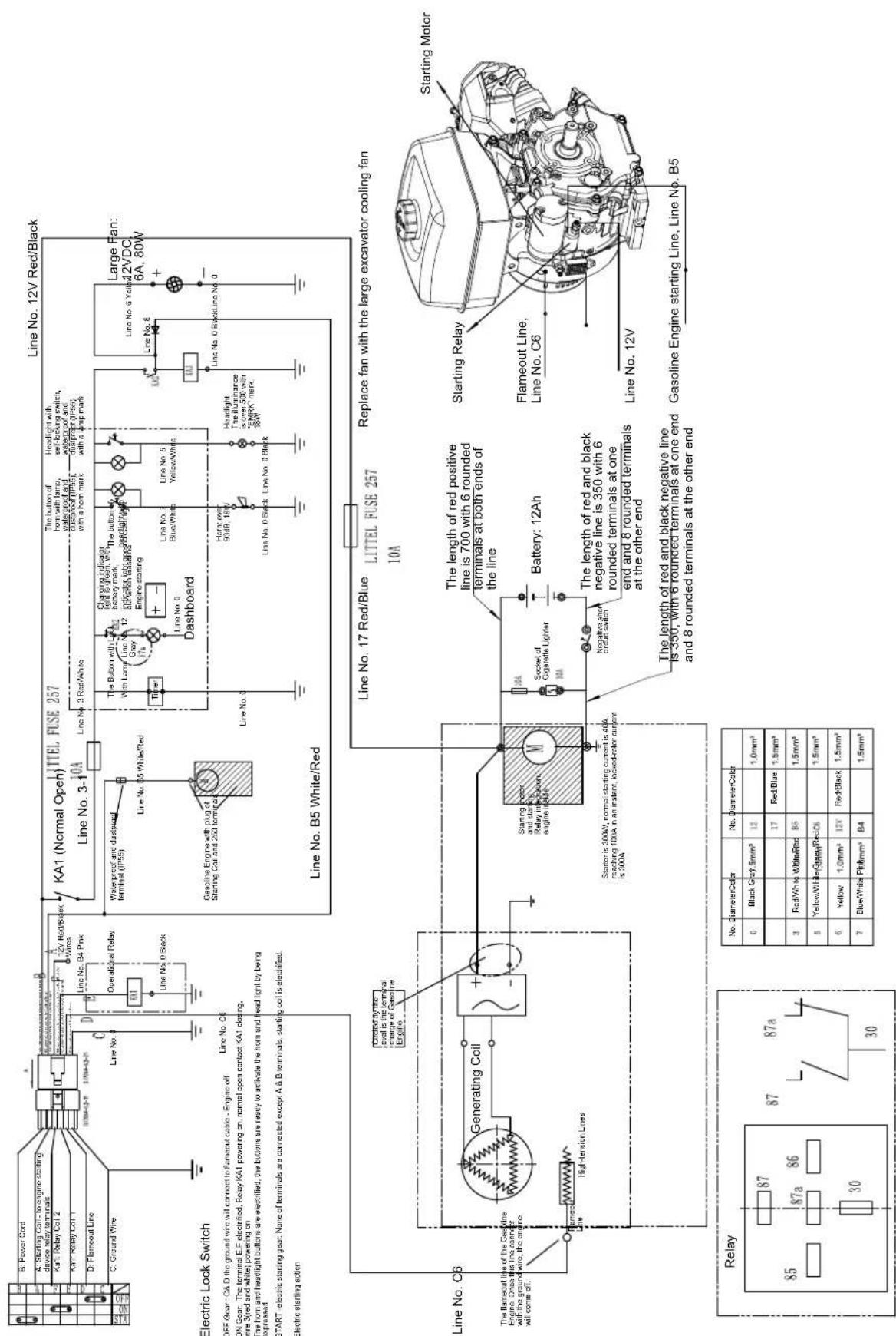

flowchart
graph TD
    A["201m"] --> B["39 017"]
    B --> C["P"]
    C --> D["17.5kPa"]
    D --> E["M"]
    E --> F["8 015"]
    F --> G["37 013"]
    G --> H["22 013"]
    H --> I["19 013"]
    I --> J["22 013"]
    J --> K["19 013"]
    K --> L["22 013"]
    L --> M["19 013"]
    M --> N["22 013"]
    N --> O["19 013"]
    O --> P["22 013"]
    P --> Q["19 013"]
    Q --> R["22 013"]
    R --> S["19 013"]
    S --> T["22 013"]
    T --> U["19 013"]
    U --> V["22 013"]
    V --> W["19 013"]
    W --> X["22 013"]
    X --> Y["19 013"]
    Y --> Z["22 013"]
    Z --> AA["19 013"]
    AA --> AB["22 013"]
    AB --> AC["19 013"]
    AC --> AD["22 013"]
    AD --> AE["19 013"]
    AE --> AF["22 013"]
    AF --> AG["19 013"]
    AG --> AH["22 013"]
    AH --> AI["19 013"]
    AI --> AJ["22 013"]
    AJ --> AK["19 013"]
    AK --> AL["22 013"]
    AL --> AM["19 013"]
    AM --> AN["22 013"]
    AN --> AO["19 013"]
    AO --> AP["22 013"]
    AP --> AQ["19 013"]
    AQ --> AR["22 013"]
    AR --> AS["19 013"]
    AS --> AT["22 013"]
    AT --> AU["19 013"]
    AU --> AV["22 013"]
    AV --> AW["19 013"]
    AW --> AX["22 013"]
    AX --> AY["19 013"]
    AY --> AZ["22 013"]
    AZ --> BA["19 013"]
    BA --> BB["22 013"]
    BB --> BC["19 013"]
    BC --> BD["22 013"]
    BD --> BE["19 013"]
    BE --> BF["22 013"]
    BF --> BG["19 013"]
    BG --> BH["22 013"]
    BH --> BI["19 013"]
    BI --> BJ["22 013"]
    BJ --> BK["19 013"]
    BK --> BL["22 013"]
    BL --> BM["19 013"]
    BM --> BN["22 013"]
    BN --> BO["19 013"]
    BO --> BP["22 013"]
    BP --> BQ["19 013"]
    BQ --> BR["22 013"]
    BR --> BS["19 013"]
    BS --> BT["22 013"]
    BT --> BU["19 013"]
    BU --> BV["22 013"]


C

D

E

F

EU Declaration of Conformity
Standard references:
EN 474-1:2006+A6:2019; EN 474-1:2022; EN 474-5:2006+A3:2013; EN474-5:2022; EN 55012:2017+A1:2009; EN ISO 12100:2010
This declaration of conformity is issued under the sole responsibility of the manufacturer.
The object of the declaration described above fulfils the regulations of the directive 2011/65/EU of the European Parliament and Council from 8th June 2011, on the restriction of the use of certain hazardous substances in electrical and electronic equipment.
Subject to change without notice
Documents registrar: Stefan Hartinger
Günzburger Str. 69, D-89335 Ichenhausen
Garantie DE
Apparent defects must be notified within 8 days from the receipt of the goods. Otherwise, the buyeris rights of claim due to such defects are invalidated. We guarantee for our machines in case of proper treatment for the time of the statutory warranty period from delivery in such a way that we replace any machine part free of charge which provably becomes unusable due to faulty material
or defects of fabrication within such period of time. With respect to parts not manufactured by us we only warrant insofar as we are entitled to warranty claims against the upstream suppliers. The costs for the installation of the new parts shall be borne by the buyer. The cancellation of sale or the reduction of purchase price as well as any other claims for damages shall be excluded.
Garantie FR


- EXC815
- Verehrter Kunde,
- Montage
- Warnung!
- Tägliche Kontrollen
- Hinweis:
- Achtung
- Schwenkbetrieb
- ⚠ Achtung
- Wichtig!
- Parken am Hang
- ⚠ Warning!
- Gefahr!
- Tägliche Kontrollen
- Montage
- Haltekralle 7915001702 (SEPARAT ERHÄLTLICH)
- Baggerdach 7915001704 (SEPARAT ERHÄLTLICH)
- Explanation of the symbols on the product
- Table of contents: Page:
- Introduction
- Manufacturer:
- Dear Customer,
- Note:
- Product description (Fig. 1 + 2)
- Scope of delivery
- Proper use
- General safety instructions
- ⚠️ DANGER
- ⚠ WARNING
- CAUTION
- NOTE!
- Working range
- Personal safety
- Safe handling of petrol
- Use and care of the machine
- Service
- Residual risks
- Technical data
- Noise and vibration
- Unpacking
- Assembly
- Fitting the operating levers
- Structure of the handlebars
- Fitting the rear-view mirrors
- Fitting the operator seat
- Warning!
- Before commissioning
- Handling the safety devices
- Operating lever safety catch
- Caution!
- Swivelling locking pin
- Daily checks
- Controls
- Commissioning
- Attention!
- before commissioning!
- Starting the engine
- Hour counter
- Reading the counter
- Checkpoints after starting the engine
- Check the following points after starting the engine, but before starting work:
- Stop the engine immediately if any of the following circumstances occur:
- Attention
- Starting the engine when cold
- Switching off the engine
- Shutting the petrol valve
- Operation
- Checking the controls during operation
- Running in the new excavator
- Oil change during the running-in phase.
- Starting up
- Adjusting the operator's seat
- After adjusting the seat, make sure that the seat adjustment is engaged.
- Work light switch
- ⚠ Attention
- Night mode
- Operating the boom
- Operating the arm
- Operating the bucket
- Swivelling operation
- Keep the work area clear!
- Important!
- Swivelling the outrigger
- Boom swivelling pedal
- Operating the levelling blade
- Driving
- Drive lever (right, left)
- Change of direction
- Turning on the spot
- Note
- Changing direction while stationary
- Changing direction while driving
- Turning on the spot
- Driving uphill and downhill
- Parking on slopes
- Important notes on operating the excavator
- Preparation for operation in cold weather
- After commissioning
- Cleaning
- Danger!
- Transport
- Transporting the excavator on a lorry
- Lifting the excavator
- Basics for lifting with chains/belts:
- Safety aspects when lifting with chains/belts:
- General guidelines for lifting:
- Lifting position (see figure below)
- Fastening the chains/straps.
- Tackle
- Lifting
- Storage
- Observe the following sequences if the excavator is to be stored for an extended period:
- Follow the procedures below if the machine is to be put into operation after a long period of storage.
- Maintenance
- Opening and closing of components
- Opening/closing the bonnet
- Daily checks
- Checking the petrol level
- Checking the hydraulic oil level
- Lubrication points
- Checking the cooling fan
- Cleaning the engine and electrical cables
- Testing the electrical circuit
- Washing the whole machine
- Regular checks and maintenance work
- Change the engine oil
- Engine oil quantity 1.1 litre
- Engine oil recommendations
- Battery maintenance
- Battery charged
- Lubricating the teeth of the swivel bearing
- Inspection and cleaning of the air filter element
- Cleaning with compressed air
- Checking the spark plug
- Maintenance of the spark plug
- Cross-references:
- Every 100 operating hours:
- Lubricating the swivel bearing
- Every 200 operating hours:
- Replacing the air filter element
- Checking the petrol line
- Every 1000 operating hours:
- Hydraulic oil check
- Annual maintenance:
- Electrical cabling and fuses
- Replacing the spark plug
- Replacing the petrol line
- Other settings and replacements
- Adjusting the crawlers
- Proceed as follows to loosen the crawlers:
- Do not crawl under the excavator.
- Crawler connecting piece
- Special instructions for the use of rubber crawlers
- Replacing the bucket
- Replacing fuses
- Regular replacement of important components
- Recommended oil types
- Fuel recommendations
- Recommended hydraulic oils
- Recommended hydraulic oil type:
- Repair & ordering spare parts
- Connections and repairs
- Important note in the case of repairs:
- Ordering spare parts
- Spare parts / accessories Article no.:
- Service information
- Disposal and recycling
- Notes for packaging
- Information on the battery act [BattG]
- Old batteries and rechargeable batteries do not belong in household waste, but must be collected or disposed of separately!
- Fuels and oils
- Troubleshooting
- Lifting capacity
- Machine states:
- ATTACHMENTS (AVAILABLE SEPARATELY)
- Excavator rake 7915001705 (AVAILABLE SEPARATELY)
- Assembly
- Excavator thumb 7915001701 (AVAILABLE SEPARATELY)
- Excavator claw 7915001702 (AVAILABLE SEPARATELY)
- Fitting the ripper tooth
- Grading bucket 7915001703 (AVAILABLE SEPARATELY)
- Excavator canopy 7915001704 (AVAILABLE SEPARATELY)
- Cher client,
- Avertissement !
- Pivotement
- Changement de direction
- Prudence
- Se garer en pente
- ⚠ Avertissement !
- Stockage
- ACCESSOIRES (DISPONIBLES SÉPARÉMENT)
- Godet râteau 7915001705 (DISPONIBLE SÉPARÉMENT)
- Butée de pelle 7915001701 (DISPONIBLE SÉPARÉMENT)
- Grappin à godet 7915001702 (DISPONIBLE SÉPARÉMENT)
- Godet de terrassement 7915001703 (DISPONIBLE SÉPARÉMENT)
- Arceau de protection 7915001704 (DISPONIBLE SÉPARÉMENT)
- Egregio cliente,
- Montaggio
- Avviso!
- Controlli quotidiani
- Importante!
- Parcheggio su un pendio
- Pericolo!
- Stoccaggio
- ⚠️ Cautela
- Controlli quotidiani
- ACCESSORI (FORNIBILI SEPARATAMENTE)
- Montaggio
- EU Declaration of Conformity
- Standard references:
- Garantie DE
- Garantie FR
Brand : SCHEPPACH
Model : EXC815
Category : Construction Equipment