EWAD910C - Computer cooling system DAIKIN - Free user manual and instructions
Find the device manual for free EWAD910C DAIKIN in PDF.
| Product type | Air-cooled chiller |
| Brand | Daikin |
| Model | EWAD910C |
| Application | Water or water-glycol cooling for computer hardware cooling systems |
| Compressor | Screw compressor (2 or 3 depending on configuration) |
| Refrigerant | R134a, GWP = 1430 |
| Power supply | Three-phase, voltage per nameplate (e.g., 400 V) |
| Ambient temperature range (storage) | -20 °C to 57 °C |
| Ambient temperature range (operation) | Up to 52 °C depending on evaporator outlet water temperature (see figure 2) |
| Evaporator outlet water temperature range | -8 °C to 16 °C (depending on ambient conditions) |
| Freeze protection | Electric heater with thermostat on evaporator (protection down to -25 °C) |
| Safety devices | Safety valves, flow switch, main switch, emergency stop |
| Installation | On concrete foundation (min. thickness 250 mm), observe minimum clearances (e.g., 1800 mm lateral, 3000 mm front/rear) |
| Recommended maintenance | Weekly (data reading), monthly (visual inspection), annually (condenser cleaning, electrical check) |
| Water filter | Mandatory on evaporator inlet (0.5 mm mesh for freecooling version) |
| Heat recovery | Optional (water heat exchanger on compressor discharge, min water temperature 28 °C) |
| Freecooling | Possible on certain versions (additional coils, 3-way or 2-way valve) |
| Compliance | European directive 2014/68/EU (category IV) |
| Warranty | 12 months from first startup or 18 months from delivery |
| Repairability | Spare parts available from the manufacturer's representative |
Frequently Asked Questions - EWAD910C DAIKIN
User questions about EWAD910C DAIKIN
0 question about this device. Answer the ones you know or ask your own.
Ask a new question about this device
Download the instructions for your Computer cooling system in PDF format for free! Find your manual EWAD910C - DAIKIN and take your electronic device back in hand. On this page are published all the documents necessary for the use of your device. EWAD910C by DAIKIN.
USER MANUAL EWAD910C DAIKIN
Installation, Operation and Maintenance Manual Installation, Operation and Maintenance Manual D–EIMAC00608-16EU
Air cooled screw chillers
EWAD\~C-SS EWAD\~C-XS EWAD\~C-PS EWAD\~C-XL EWAD\~C-SL EWAD\~C-PL EWAD\~C-SR EWAD\~C-XR EWAD\~C-PR
Refrigerant: R-134a
Cooling capacity from 619 to 2008 kW
natural_image
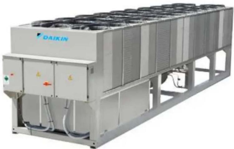
Exterior view of a large industrial HVAC unit with visible branding (DAIKIN logo), no readable text or symbols beyond branding.
| English | 9 | |
| Deutsch | 20 | |
| Français | 30 | |
| Nederlands | 42 | |
| Español | 53 | |
| Italiano | 64 | |
| Ελληνικά | 75 | |
| Português | 87 | |
| Русский | 98 | |
| Swedish | 109 | |
| Norsk | 120 | |
| Finnish (Suomi) | 131 | |
| Polski | 142 | |
| Čech | 153 | |
| Hrvat | 164 | |
| Magyar | 175 | |
| Român | 186 | |
| Slovenski | 198 | |
| Български | 209 | |
| Slovenský | 220 |
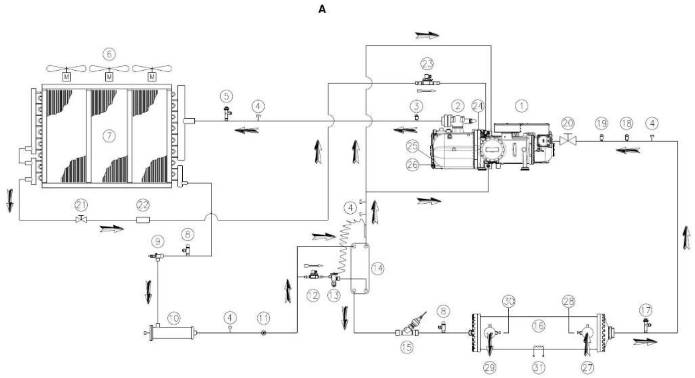
A – Typical refrigerant circuit - Water inlet and outlet are indicative. Please refer to the machine dimensional diagrams for exact water connections.
A – Typischer Kühlkreislauf – Wasser-Ein- und Ausgang sind unverbindlich. Bitte beziehen Sie sich auf die Geräteabmessungs-Diagramme für genaue Wasseranschlüsse.
A – Circuit de refroidissement typique – L'arrivée et la sortie d'eau sont reportés à titre indicatif. Veuillez vous reporter aux schémas dimensionnels de la machine pour identifier les raccordements exacts de l'eau.
A – Typisch koelmiddelcircuit – Waterintlaat en –uitlaat zijn indicatief. Zie de dimensionele diagrams van de machine voor de juiste wateraansluitingen.
A – Circuito de refrigeración típico - la entrada y la salida de agua son indicativas. Consulte los diagramas de dimensiones de la máquina para conocer las conexiones de agua exactas.
A – Tipico circuito refrigerante – L'ingresso e l'uscita dell'acqua sono indicativi. Consultare i diagrammi dimensionali delle macchine per i collegamenti idraulici esatti.
Α – Τυπικό κύκλωμα ψυκτικού μέσου – Η παροχή εισόδου και εξόδου νερού είναι ενδεικτική. Ανατρέξτε στα διαγράμματα διαστάσεων του μηχανήματος για τις ακριβείς συνδέσεις νερού.
A – Circuito típico refrigerante – Entrada e saída de água são indicativas. Consultar os diagramas dimensionais da máquina para as conexões certas da água.
A – Стандартный контур хладагента – Впускные и выпускные водопроводные отверстия показаны лишь для примера. Для определения параметров подключения водопровода следует учитывать данные габаритных чертежей оборудования.
A – Typisk kylkrets – Vattenledningens inlopp och utlopp är ungefärliga. Se maskinens dimensionsdiagram för exakta vattenanslutningar.
A – Typisk kjølemediekrets - vanninntak og -uttak er kun antydninger. Se maskinens måltegninger for nøyaktige vanntilkoblinger.
A – Tyypillinen jäähdytyspiiri – Vedentulo- ja poistoaukot ovat viitteelliset. Katso tarkat vesiliitännät koneen mittakaavioista.
A – Typowy obwód czynnika chłodniczego – wskazane miejsce dopływu i odpływu wody ma charakter poglądowy. Dokładne miejsca podłączeń instalacji wodnej wskazano na rysunkach wymiarowanych.
A – Typický chladící obvod – Přívod a odvov dvoudy jsou jednoznačné. Přesný postup připojení vody viz nákresy stroje.
A – Tipični rashladni krug – ulaz i izlaz za vodu su samo za indikaciju. Pogledajte mjerne skice stroja ako želite točan položaj priključaka za vodu.
A - Tipikus hütő áramkör - A vízbeömlő- és kiömlönyílás jelzésszerű. A pontos összeköttetésekért lásd a berendezés szerkezeti rajzát.
A – Circuit de răcire tipic – Intrarea și ieșirea pentru apă au rol indicativ. Vă rugăm să consultați diagramele mașinii cu dimensiunile pentru conexiunile exacte la apă.
A – Tipičen tokokrog hladilnega sredstva – vodni dovod in odvod sta indikativna. Za natančne vodne povezave glejte diagrame dimenzij naprave.
A – Типична охладителна верига – Водните входове и изходи са указателни. Моля, направете справка с диаграмите с рзмерите на машината за точните водни връзки.
A – Typický obvod chladiacej zmesi. Vstup a výstup vody sú indikativne.. Presná poloha pripojok vody je vyznačená na rozmerových výkresoch zariadenia.
flowchart
graph TD
    A["Feed Tank ⑦"] --> B["Reactor Unit ②"]
    B --> C["Valve ⑤"]
    C --> D["Column ③"]
    D --> E["Valve ②"]
    E --> F["Column ②4"]
    F --> G["Valve ①"]
    G --> H["Column ②0"]
    H --> I["Valve ⑲"]
    I --> J["Column ②6"]
    J --> K["Valve ②5"]
    K --> L["Column ②3"]
    L --> M["Valve ②2"]
    M --> N["Column ②1"]
    N --> O["Valve ②0"]
    O --> P["Column ②9"]
    P --> Q["Valve ⑩"]
    Q --> R["Column ⑪"]
    R --> S["Valve ⑫"]
    S --> T["Column ⑭"]
    T --> U["Valve ⑬"]
    U --> V["Column ⑮"]
    V --> W["Valve ⑰"]
    W --> X["Column ⑱"]
    X --> Y["Column ⑲"]
    Y --> Z["Valve ⑳"]
    Z --> AA["Column ⑳"]
    AA --> AB["Valve ⑰"]
    AB --> AC["Column ⑱"]
D-EIMAC00608-16EU - 3/234
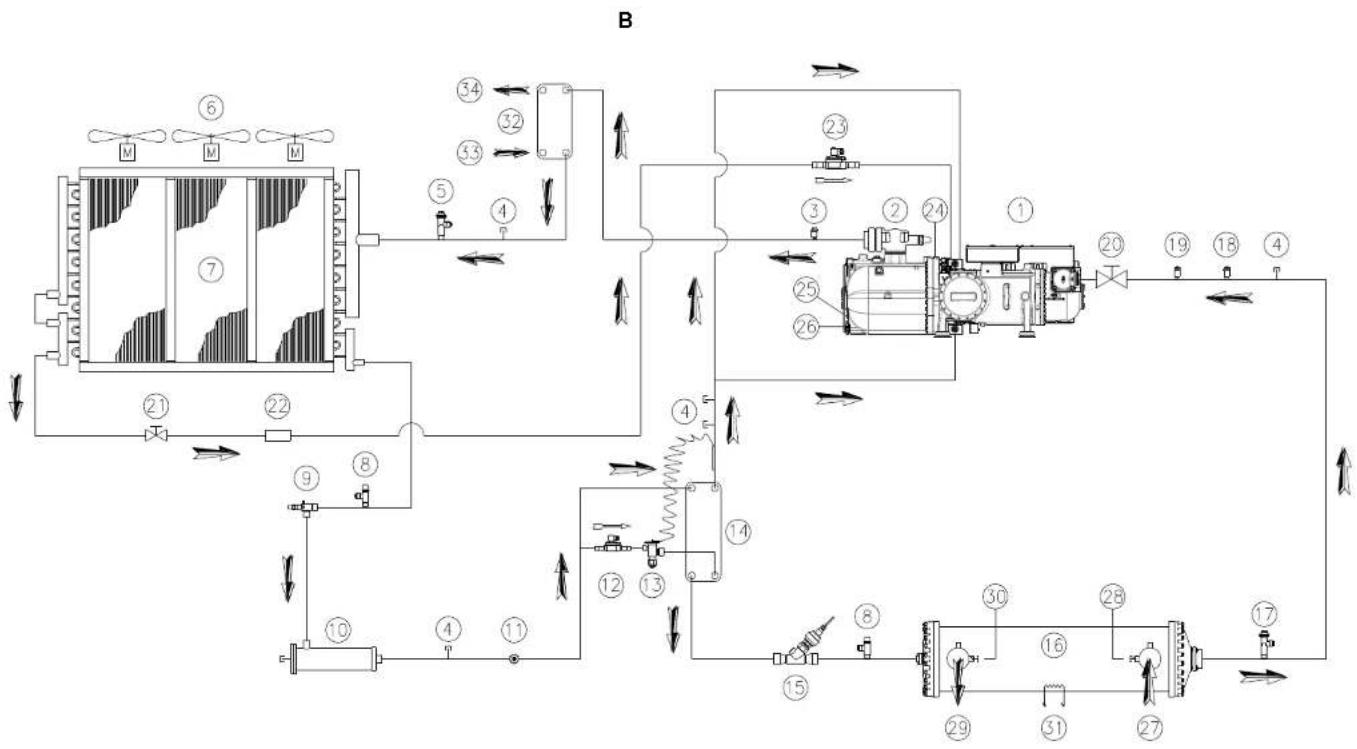
B – Typical refrigerant circuit with heat recovery - Water inlet and outlet are indicative. Please refer to the machine dimensional diagrams for exact water connections.
B - Typischer Kühlkreislauf mit Wärmerückgewinnung – Wasser-Ein- und Ausgang sind unverbindlich. Bitte beziehen Sie sich auf die Geräteabmessungs-Diagramme für genaue Wasseranschlüsse
B – Circuit de refroidissement typique avec récupération de chaleur – L'arrivée et la sortie d'eau sont reportés à titre indicatif. Veuillez vous reporter aux schémas dimensionnels de la machine pour identifier les raccordements exacts de l'eau.
B – Typisch koelmiddelcircuit – Waterintlaat en –uitlaat zijn indicatief. Zie de dimensionele diagrams van de machine voor de juiste wateraansluitingen.
B – Circuito de refrigeración típico con recuperación de calor – La entrada y la salida de agua son indicativas. Consulte los diagramas de dimensiones de la máquina para conocer las conexiones de agua exactas.
B – Tipico circuito refrigerante con recupero di calore – L'ingresso e l'uscita dell'acqua sono indicativi. Consultare i diagrammi dimensionali delle macchine per i collegamenti idraulici esatti.
B – Τυπικό κύκλωμα ψυκτικού μέσου με ανάκτηση θερμότητας – H παροχή εισόδου και εξόδου νερού είναι ενδεικτική. Ανατρέξτε στα διαγράμματα διαστάσεων του μηχανήματος για τις ακριβείς συνδέσεις νερού.
B – Circuito típico refrigerante com recuperação de calor -- Entrada e saída de água são indicativas. Consultar os diagramas dimensionais da máquina para as conexões certas da água.
В – Стандартный контур хладагента с регуоперацией тепла – Впускные и выпускные водопроводные отверстия показаны лишь для примера. Для определения параметров подключения водопровода следует учитывать данные габаритных чертежей оборудования.
B – Typisk kylkrets med värmeåtervinning – Vattenledningens inlopp och utlopp är ungefärliga. Se maskinens dimensionsdiagram för exakta vattenanslutningar.
B – Typisk kjølemediekrets med varmegjenvinning - vanninntak og -uttak er kun antydninger. Se maskinens måltegninger for nøyaktige vanntilkoblinger.
B – Tyypillinen jäähdytyspiiri lämmön talteenotolla - Vedentulo- ja poistoaukot ovat viitteelliset. Katso tarkat vesiliitännät koneen mittakaavioista.
B – Typowy obwód czynnika chłodniczego z odzyskiem ciepła. Wskazane miejsce dopływu i odpływu wody ma charakter poglądowy. Dokładne miejsca podłączeń instalacji wodnej wskazano na rysunkach wymiarowanych.
B – Typciký chladici obvod s rekuperaci teplat – Přívod a odvod vody jsou průkazné. Přesné zapojení viz nákresy stroje.
B – Tipični rashladni krug s povratom topline – ulaz i izlaz za vodu su samo za indikaciju. Pogledajte mjerne skice stroja ako želite točan položaj priključaka za vodu.
B - Tipikus hütő áramkör hővisszanyerő berendezéssel - A vízbeömlő- és kiömlönyíllás jelzésszerű. A pontos összeköttetésekért lásd a berendezés szerkezeti rajzát.
B – Circuit de răcire tipic cu recuperare de căldură. Intrarea și ieșirea pentru apă au rol indicativ. Vă rugăm să consultați diagramele mașinii cu dimensiunile pentru conexiunile exacte la apă.
B – Tipičen tokokrog hladilnega sredstva z obnavljanjem toplote – vodni dovod in odvod sta indikativna. Za natančne vodne povezave glejte diagrame dimenzij naprave.
В – Типична охладителна верига с възстановяване на топлината – Водните входове и изходи са указателни. Моля, направете справка с диаграмите с рэмерите на машината за точните водни връзки.
B – Typický obvod chladiacej zmesi s regeneráciou tepla. Vstup a výstup vody sú indikativne. Presná poloha prípojok vody je vyznačená na rozmerových výkresoch zariadenia.
flowchart
graph TD
    A["1"] --> B["20"]
    B --> C["19"]
    C --> D["18"]
    D --> E["4"]
    E --> F["25"]
    F --> G["26"]
    G --> H["24"]
    H --> I["3"]
    I --> J["23"]
    J --> K["34"]
    K --> L["32"]
    L --> M["5"]
    M --> N["4"]
    N --> O["7"]
    O --> P["6"]
    P --> Q["21"]
    Q --> R["22"]
    R --> S["9"]
    S --> T["8"]
    T --> U["10"]
    U --> V["4"]
    V --> W["11"]
    W --> X["12"]
    X --> Y["13"]
    Y --> Z["14"]
    Z --> AA["15"]
    AA --> AB["8"]
    AB --> AC["30"]
    AC --> AD["16"]
    AD --> AE["28"]
    AE --> AF["27"]
    AF --> AG["17"]
    AG --> AH["29"]
    AH --> AI["31"]
    AI --> AJ["27"]
D-EIMAC00608-16EU - 5/234
| English | Deutsch | Français | Nederlands | Español | Italiano | |
| 1 | Compressor | Verdichter | Compressor | Compressor | Compressor | Compressor |
| 2 | Discharge shut off valve | Vorlaufabspenteril | Robinet de refoulement | Persafaluter | Grid de salida | Rubinetto di mandato |
| 3 | High-pressure transducer | Hochruckensor | Transductor haute pression | Omester hoge druk | Transductor de alta presión | Traslutoro alta pressione |
| 4 | Servoo port | Wartungskappe | Port de maintensoe | Dienstulkje | Portillo para assistencia | Valvola di servizio |
| 5 | High-pressure safety valve | Hochruck-Sicherheitsventil | Soupape de sécurite haute pression | Veilighedeklep hoge druk | Valvula de seguridad de alta presión | Valvola di sicurezza alta pressione |
| 6 | Axis ventilator | Axisventilator | Ventilateur axlei | Axiale ventilator | Ventilactor axial | Vontiatore assale |
| 7 | Condorsor coil | Vorflüssigromistor | Battero a condonsation | Condorsorgop | Batoria conconsadora | Batteria conconsanto |
| 8 | Load Valve | Lastvoltil | Vanne do charge | Laacklep | valvula de carga | Valvola di carcamento |
| 9 | Liquid line isolating valve | Abserventil Flüssigköttsleitung | Vanne d'isolement de la ligne du liquide | Ataluter vioestoflin | Valvula de corte de la líneas del liquido | Valvola isolante líneas del liquido |
| 10 | Dehydration filter | Entwässerungsefilter | Filtre deshydrateur | Dehydratatefilter | Filtro deshidratisator | Filtro dedristatore |
| 11 | Liquid and humidity indicator | Flüssigkötts- und Feuchigkeitsanzeige | Indicateur de liquide et humidite | Voestof- en vochtigheldsindicator | Indicador de liquido y numedso | Indicatore di liquido e umidità |
| 12 | Economiser scleroid valve | Scleroidventil Economiser | Vanne solénoide économiser | Magnetiekp economiser | Valvula solenode economicizador | Valvola solenode economicizzatore |
| 13 | Economiser thermostatic expansion valve | Thermostatisches Expansionsventil Economiser | Défendeur thermostatique économiser | Thermostallich expansileventil economiser | Valvula de expansion thermostaltica del economicizador | Valvola di espansione thermostaltica economicizzatore |
| 14 | Economiser (not available for EWAD650C SS/SL/SR) | Economiser (nicht verfügbar für EWAD650C SS/SL/SR) | Économiser (non disponible pour EWAD650C SS/SL/SR) | Economiser (niet beschikbaar voor EWAD650C SS/SL/SR) | Economizador (no disponible para EWAD650C SS/SL/SR) | Economizatore (non disponible per EWAD650C SS/SL/SR) |
| 15 | Electronic expansion valve | Elektronisches Expansionsventil | Défendeur électronique | Elektronisch expansileventil | Valvula de expansion electrónica | Valvola di espansione elektronica |
| 16 | Evaporator | Verdampfer | Evaporateur | Verdamper | Evaporador | Evaporatore |
| 17 | Low pressure safety valve | Niederdruck Sicherheitsventil | Soupape de sécurité à basse pression | Veilighedeklep lage druk | Valvula de seguridad de baja presión | Valvola di sicurozza a bassa pressione |
| 18 (ST) | Suction temperature probe | Ansaugtenperaturführer | Sonde de température aspiration | Temperatuursonde aanzuiging | Sonda de temperatura en aspiración | Sonda temperatura aspirazione |
| 19 (EP) | Low pressure transducer | Niederdrucksensor | Transductor basse pression | Onvetier lage druk | Transductor de baja presión | Traslutlore bassa pressione |
| 20 | Suction shut off valve | Abserventil Saugoltung | Robinet d'aspiration | Aanzuging afsultifico | Grito de aspiración | Rubinetto di aspirazione |
| 21 | Liquid Injection shut off valve | Asparventil der Flüssigköttsoinpritzung | Vanne d'arrêt de injection du liquide | Atalutidep voor viselatotinjectie | Grito de inyesción de liquido | Valvola di chiusura a iniezione liquida |
| 22 | Liquid Injection mesh filter | Gewerbattar der Flüssigköttsoinpritzung | Filtre a mallets pour l'injection du liquide | Fillet met masen voor vislostofinotic | Filtro de malls de inyesción de liquido | Filtro in mesh a iniezione liquida |
| 23 | Liquid injection scleroid valve | Scleroidventil zur Flüssigköttsainpritzung | Vanne solénoide pour injection ou liquids | Magnetiokp voor voestorinjectie | Valvula solenode para inyesción de liquido | Valvola solenode per iniezione di liquido |
| 24 (F13) | High-pressure switch | Maximun-Druokavoror | Prossostat haute pression | Druokopisar hoge druk | Prossostato de esta presión | Prossostato ata pressione |
| 25 (DT) | Discharge temperature sensor | Auslaut-Temperatur-Sensor | Capteur de la température de refoulement | Parstomperatursensor | Sensor de temperatura de salida | Sensor de temperatura di scarico |
| 26 (OP) | Oil pressure transducer | Okruckensor | Transductor pression de frühe | Onvetier oliedruk | Transductor de presión del aceite | Traslutlore pressione olio |
| 27 | Water inlet connection | Anschluss Wasseraufaul | Raccordement de l'arrivée d'eau | Ansaluting ingang water | Conexión de la entrada de agua | Collegamento di ingresso acqua |
| 28 (EEWT) | Water entering temperature probe | Temperatuiführer Wasseraufaul | Sonde de température entée eau | Temperatuursonde waterloevser | Sonda de temperatura de entrada del agua | Sonda temperatura ingresso acqua |
| 29 | Water outlet connection | Anschluss Wasseraufaul | Raccordement de la sortie d'eau | Ansaluting ingang water | Conexión de la salida de agua | Connessione uscita acqua |
| 30 (ELWT) | Water leaving temperature probe | Temperatuiführer Wassorauslauf | Sonde de température sortie eau | Temperatuursonda waterulait | Sonda de temperatura de salida del agua | Sonda temperatura uscita acqua |
| 31 (RS) | Evaporator heater | Verdampfer Helzer | Réchaufleur de l'évaporateur | Verwarming verdamper | Calendador del evaporador | Riscaldatore con evaporatore |
| 32 | Host recovery | Warmonlockgownimg | Récapération de cholaur | Wamtotorugownimg | Recuporación de calor | Recupcoro del calvo |
| 33 | Water inlet connection | Anschluss Wassorzulauf | Raccordement de l'arrivée d'eau | Wastrinvoraansluiting | Conexión de la entrada de agua | Collegamento di ingresso del agua |
| 34 | Water outlet connection | Verdichter | Raccordement de la sortie d'eau | Wastrinvoraansluiting | Conexión de la salida de agua | Collegamento di uscita dell'acqua |
D-EIMAC00608-16EU - 6/234
| Ελληνικά | Português | Русский | Swedish | Norsk | Finnish | Polski | Cesky | |
| 1 | Συμπονίας | Compressor | Komiprescor | Kompressor | Kompressor | Kompressori | Sprężinka | Kompressor |
| 2 | Σρογωνολτική ρολβίδα εκερσίς | Tomeira de mandada | Otocchony klasan na nametania | Tryckarsängningsventil | Avsängningsventil pa učtop | Poiskon lyhijenyeventili | Zawór llocziny | Výllashný kohoulek |
| 3 | Μεταραστείας, υρημής πειστες | Transdutor de alta pressão | Датник высокого давления | Högtrycksomvandare | Hoptykksanformer | Korkepsahensluri | Przetvonnik wyscklago citrinna | Transduktor vysckého Itaku |
| 4 | Προτα βοηβείας | Porta para assistência | Scotrobejho loix | Serviceloucha | Serviceluke | Huoltoluku | Drizwiszól serwikowe | Servieni dvilks |
| 5 | Βολβίδα σαραναλος υρημές πειστες | Valvula de segurança de alta pressão | Предохранительный клапанho высокому давление | Högtrycks sikarinstventil | Sikkorhotesventil for haytryk | Korkepsaina turvaventili | Zawór bezpieczensitika wyscklago citrinna | Bezpečnosni ventil vysokéna Itaku |
| 6 | Λοχρεστήρας θόσα | Versificador social | Oversoi aninikaner | Axialáški | Axialaverilator | Aklandulatalla | Wensfistor osiotov | Axalani ventilátor |
| 7 | Μποταρία συμποκυνατης | Rotaia condorsante | Kondorsato | Kondorsato-bantari | Kondorsator-bantari | Jažendytyskorulka | Wępowntica skopioacza | Kondorszár batorta |
| 8 | Βαθμίδα αξαξης φαρτιος | Valvula de carga | Нагука valve | Laddingsventil | Load Valve | Latausventili | Zawór wiotowy | Zattitani ventoli |
| 9 | Βαθμίδα απαρανανητας γραφής γρασό | Tomora de isiamencia da lima do liquido | Otocchony klasan terpainglysskoi piniu | Isaieringsventil vizskoledning | Avstengningsventil pa flytends inje | Nasteljan oratyasventili | Zawór odionagcy litią plynu | Iztazalni kohoulek linis kapolinny |
| 10 | Φλήρο αφογρανετης | Filtro desiribator | Filíthr desiribitor | Aviktiringsfilter | Aviktiringsfilter | Kuvauszuodatin | Filtr owadinizcra | Filtr dehydridron. |
| 11 | Ενόση υροσί και ιναρασίας | Indicador de liquido e humpadde | Anikimator planissima | Vatska och hunsara | Vasske og fuktighets saglass | Nasta ja kastaasmentai | Wskaźnik plynu itadiogi | Ukrazatal kapaliny a vikostii |
| 12 | Ηλεκρομονητική βαρλήδα economicista | Valvula salanóid para o economicista | Collenaonidный клапан экономизера | Magnatventil kyling | Magnatventil for tedavarinsteventer | Säästayyskön solanndventil | Elektromagnatyzny zawór akonomizera | Selanodni ventil akonomizadora |
| 13 | Εερμοτοπεία βαβάλικα εκπώνωτης εκοποπεία | Valvula de expansão temostática para o economicista | Tormostattiskola persimontaneous klanan экономизера | Tormostattisk expansanestventil kyling | Tormostattisk expansanestventil ter tedavarinsteventer | Säästayyskön temostavnitron paesunlaventil | Temostatystyny zawór rozpreżny ekonomizera | Topalny expanzi ventil ekonomizadora |
| 14 | Εκροπεία (dev διαίδεια γα EWAD650C-SS/SL/SR) | Economizador Inão disponível para EWAD650C-SS/SL/SR) | Σικολημασορ (neudostytima для EWAD650C-SS/SL/SR) | Kyling (inte tillgängligit für EWAD650C-SS/SL/SR) | Fodewannelsvoramer (likko tillgjengelig für EWAD650C-SS/SL/SR) | Säästayyskäki (ei käylettävisä EWAD650C-SS/SL/SR) | Ekonomizer (niedoslepnie dla EWAD650C-SS/SL/SR) | Ekonomizátor (nonl k disporici pro EWAD650C-SS/SL/SR) |
| 15 | Ηλεκρονική βαβάδα εκκεναστε) | Valvula de expansão elektránica | Электронный ресширительный клanan | Elektronik expansionsventil | Elektronik ekspansponsventil | Elektronirini paesunlaventili | Elektronicony zawér rozpreżny | Exzanuzi elektronický vend |
| 16 | Εξωμετής | Evaporador | Papariterite | Forangare | Evaporator | Hyrystin | Paroxnik | Evaporator |
| 17 | Βαθμίδα σαραναλος χαγμήκε πειστες | Valvula de segurança a baska pressão | Predохранительный клапан no ikomou dynamimento | Lagnycks sakerhelsventil | Sikerberelsventil for lasvryek | Maladapare turvaventili | Zawór bezpieczensitika nislego citrinna | Bezpečnosni ventil nižkého Itaku |
| 18 (ST) | Αυθήτηρας, δερεικραστικε συρασσετακ | Sonda da temperatura de aspiração | Датник температуры на васывании | Sond suglemperatur | Temperaturieler i inniep | Imun lampößä anluri | Sonda temperatury zasysania | Tezelna sonda nasávání |
| 19 (EP) | Μεταραστεία χεμμήκε πειστες | Transdutor de baska pressão | Датник шихого давление | Lagnycksomvandare | Lavtryksomvandare | Malalapaanartui | Przetvonnik nislego citrinia | Transduktor nirköhe taku |
| 20 | Σπρογωνολτική βαβάλικα συρασσετακ | Tomera da aspiração | Otocchony klasan na касывелики | Bugastängningsventil | Avstengningsventil pa innles | Imuhsna | Zawór saswny | Nasávačai kohoutak |
| 21 | Σπρογωνολτική βαβάλικα εγχυγίας γρασό | Valvula de conte de injecção de liquido | Beryrscse jewejsico zeneronial klanan | Avstengningsventil für valtsakinjeonsring | Flytends injpakson stangovanti | Nastlon nuskutukson sujkuvanteli | Zawór zamykajęcy witryak plynu | Vattikovaní uzatravaci villti |
| 22 | Φλήρο παμγατας εγχυγίας γρασό | Filtro de malha para inyega de liquido | Xuhtine uitysekii sonctyati filiporter | Náttiter für vätskinjeinsring | Flytends injpakson mesh titer | Nastlon nuskutukson aritalvanko | Elektrozawor zamykajęcy witryak plynu | Vattikovaní sitkový titir |
| 23 | Ηλεκρομονητική βαρλήδα πειστες γρασό | Valvula salanóid para inyega de liquido | Cosonilizität imalan verpuraivania jewejsico | Magnatventil für vätskinjeinsring | Magnatventil for vasankysaksjon | Soconadventilni nastanakutubson | Zawór elektronagcryzny wtyvävalenta plynu | Selanodni ventil pro vestikovaní kapaliny |
| 24 (F13) | Δεσσοπτης πειστες υμηλής Φικής Φικής Φικής Φικής Φικής Φικής Φικής Φικής Φικής Φικής Φικής Φικής Φικής Φικής Φικής Φικής Φικής Τεροσία | Presozotato alte prasação | Reba浜ikojo | Högtrycksamtrane | Hoytryksansratze | Korkepsaina lytkin | Presozat wysokstego citrinia | Presozat wysokstego taku |
| 25 (DT) | Αυθήτηρας δερεικραστικε εκκενας | Transdutor de alta pressão | Датник температуры резонда | Temperatureond für utönnring | Ustlop temperaturesnor | Vzasuwapeus lampößä anluri | Ozrujk temperatury na kyjistu | Vyoti leptotni Öldo |
| 26 (OP) | Μεταραστεία πειστες λαβασ | Transdutor de pressão de elec | Датник давления масла | Oletocyksomvandare | Oletocykonformer | Olypainverluri | Przetvonnik cártenia oleju | Transduktor Itaku oleje |
| 27 | Σύδεση συδου νεροσί | Conexão de entrada de agua | Вход воды | Ansturlung vattenirlopp | Forbindelse for vanminirop | Veden sleänmenerofilos | Podłączenie doplywu wody | Zazojení vatu pup vody |
| 28 (EEWT) | Αυθήτηρας δερεικραστικε εκοδου νεροσί | Sonda de temperatura da entrada da agua | Датник температуры воды на выходе | Temperaturond inloppovalien | Temperaturieler for vanin i inngang | Veden sleänmeneron lampälla anluri | Sonda temperatury doplywu wody | Tezelna sonda vatu pup vody |
| 29 | Συδεση εξαδου νεροσί | Consexão de salida de água | Выход воды | Ansturlung vattenirlopp | Forbindelse for vaninilap | Veden ulosukolites | Podłączenie odplywu wody | Zazojení výstup vody |
| 30 (ELWT) | Αυθήτηρας δερεικραστικε εξαδου νεροσί | Sonda de temperatura da salida da agua | Датник температуры воды на выходе | Temperaturond inloppovalien | Temperaturieler for vanin i inngang | Ulosulevan veden lampälla anluri | Sonda temperatury doplywu wody | Tezelna sonda vatu pup vody |
| 31 (RS) | Εερμοτοπείας ερατιμείη | Aquecedor de evaporador | Коридитель нагреватель | Förðanvarname | Varmovekaler med varmagitarvirering | Haindturman lámmin | Podgrzewaar parawnika | Vysarnik |
| 32 | Αυθήτηρας δεραστικε ταροσία | Responparação da Caor | Упликация totale | Varmovekenning | Varmovekenning | Lámmón talcoancho | Odzyk clople | Relo parasca topa |
| 33 | Συδεση συδου νεροσί | Consexão de entrada de agua | Podnikacinse 対虹 на выходе | Ansturlung für vattenirlopp | Forbindelse for vanminiep | Vedonortapuran listânia | Podłączenie doplywu wody | Vitokové hrido |
| 34 | Συδεση εξαδου νεροσί | Consexão de salida de água | Podnikacinse 対虹 на выходе | Ansturlung für vattenirlopp | Forbindelse for vaninulap | Vederpostopalkon listânia | Podłączenie odplywu wody | Ogdopadli brile |
D-EIMAC00608-16EU - 7/234
| Hrvalski | Magyar | Român | Slovenski | Български | Slovenský | |
| 1 | Kompresor | Kompresszor | Kompressor | Kompressor | Kompressor | Kompressor |
| 2 | Zsaoomi ventil za praznjanje | Bzfolyó izáró casp | Robinet ovesuare | Izpustni zaporni ventil | Kran za podavane | Vytlačný konúlik |
| 3 | Visokolaični mjeni pretvarac | Nagy nyomás transzuktor | Traductor inaltá presiune | Visokolaični prestavljaiec | Konevator nicsko najinane | Transduktor vysokého tlaku |
| 4 | Servisni priklujčak | Szerviz ajtó | Uşaj pentru asistenjá | Servisni vhod | Обслугавш люк | Servisni dviera |
| 5 | Sigumosni ventil visoki pritisak | Bztionsági szlep nagy nyomás | Valvá de siguranjá inaltá presiune | Visokolaični varnostni ventil | Предуазен клапан высоко najargane | Bezpečnostný ventil vysokého tlaku |
| 6 | Aksijalni ventilator | Tongelyranyú ventilátor | Ventilator axial | Aksialni ventilator | Вентиатори за извеждане | Axialny ventilator |
| 7 | Spirala ukapljivača | Kondonzsló ogysóg | Baterie do condonsaro | Tuljava kondonzatorja | Kondenziracha bateirja | Kondenzněna bateira |
| 8 | Verilli za punjenje | Tõltõszelep | Supapá de admiste | Ventil za polijnje | Klapan za natoparavneto | Venilli zafaženia |
| 9 | Izoloicjeki ventil linja tekućine | Folyadók izolálo szelop | Valvá izolare line de lichid | Izoliacijski ventil tekočinske linja | Izoiniprač klapan pinna na техностva | Izolačný konútik linie kvapaliny |
| 10 | Filter za odetranjivanje vlago | Viztelenitó szluró | Filtru dosnildrator | Sulimli filter | Деюдривац фильтр | Filter odohytratora |
| 11 | Indikator tekućine i viznosti | Polyadek es nedvesság mulató | Indicator de lichid si umiditate | Sulikator tekočine in vlage | Индикator за течност и власност | Ukazovstef kvapaliny a vitkosti |
| 12 | Venilli solenoid ekonomizator | Ekhültó (economiser) szolenoid szelep | Valvá solenoida economizor | Magnetofermični ventil grelnika | Klapan зареждане тописобвенник | Soleniočný ventil ekonomizatora |
| 13 | Ventil za termostatoku ekspanziju ekonomizatora | Ekhültó (economiser) hőszabalyozú szelop | Valvá de expansiune temostatica economizor | Termostalski ekspanzijski ventil grelniku | Klapan термостатично разширение теплобменника | Terpelný expanzný ventil ekonomizatora |
| 14 | Ekonomizator (nje dostupna za EWAD650C-SS/SL/SR) | Ekhültó (economiser) (nem áll rendelkevisze EWAD650C-SS/SL/SR) | Economizor (nu este disponibil pentru EWAD650C-SS/SL/SR) | Grašnik (ni na voljo za EWAD650C-SS/SL/SR) | Теппособменник (wie со продлага за EWAD650C-SS/SL/SR) | Ekonomizator (Nic je k dispozici pre EWAD650C-SS/SL/SR) |
| 15 | Elektromicki ekspanzijski ventil | Elektromics szabályozószelop | Valvá de expansiune electronică | Elektromski ekspanzijski ventil | Klapan за електронно разширение | Expanzný elektronický ventil |
| 16 | Ispartařač | Párovjogsté | Vaporzator | Izparlinik | Изапатор | Evaporátor |
| 17 | Niskoltačni sigumosni ventil | Bztionsági szlepel niacsony nyomás | Valvá de siguranjá jossá presiune | Nizkotačni varnostni ventil | Предуазен клапан за ниско najargane | Bezpečnostný ventil nizkeho tlaku |
| 18 (ST) | Temperatura sonda usisa | Elsztivast hőmérsékletmérő szonda | Sondia de temperatură aspiratie | Sonda temperature v sosalnom sekologru | Температурна сонда за заскуване | Terpelná sonda nasátvana |
| 19 (EP) | Transduktor nizek pritisak | Kis nyomás transzuktor | Traductor presiune jossá | Nizkotačni pretvornik | Конавтор ниско najargane | Transduktor nizkeho tlaku |
| 20 | Ventilli za zafvaranje usisa | Elsztivó zárócsap | Robinet de aspiratie | Ventil za zicop sesanja | Kran za заскуване | Nasávací konulik |
| 21 | Ventilom na ubrizgavanjem tekućine | Polyadek bofocekiondozós izáró szelop | Supapá obturatosne injecție cu lichid | Izklopnii ventil tekočega vorizgavanja | Kran za инеквигране на течност | Uzatvaraci ventil pro vstrokovenilo kvapaliny |
| 22 | Mrezašt filter za ubrizgavanje tekućine | Polyadek bofocekiondozós had szuró | Filtru cu sită metalcă injecție cu lichid | Mrezní filter tekočega vorizgavanja | Мрекест фильтр за инеквигране на течност | Sitkovy fitor pro vstrokovanio kvapaliny |
| 23 | Ventilli za prekid ubrizgavanja tekućine | Polyadek beforeskendező szolonod szelop | Valvá solenoida pentru injecție lichidului | Elektromagnetni ventil tekočega vorizgavanja | Klapan зареждане за инеквигране на течност | Soleniočný ventil pre vstrekovanje kvapaliny |
| 24 (F13) | Mjerac pritiska visoki pritisak | Nagy nyomás nyomáskapospóló | Presostat inaltá presiune | Vlasoktačni presostat | Kontactor ограничител вискою напагане | Presostat vysokého tlaku |
| 25 (DT) | Senzor temperature na ispuhu | Kimenet nőmérséklet ezékelő | Senzor izchodne temperature | Иходен температурен сенсор | Senzor teploby na odvode | |
| 26 (OP) | Mjeri pretvarae iliaka ulga | Ojinyomás transzuktor | Traductor presiune ulei | Preslavijalec oljnega tlaka | Конавтор najargane на маслото | Transduktor tlaku oleja |
| 27 | Priključak za ulaz vode | Viz bemeneli csatlakozás | Conexiune intrare apá | Povezava dovoda vode | Brýzka вход aoda | Zapojenie vistupu vody |
| 28 (EEWT) | Temperatura sonda ulaz vode | Bemeneti vizhőmérséklet mérő szonda | Sondia temperatură apá intrare | Sonda temperature vhodne vode | Температурна сонда вход aoda | Terpelná sonda vistupu vody |
| 29 | Priključak za izlaz vode | Vizlearesztő csatlakozás | Conexiune igire apá | Priključek za odvod vode | Brýzka вход aoda | Zapojenie vystupu vody |
| 30 (ELWT) | Temperatura sonda izlaz vode | Kimeneti vizhőmérséklet mérő szonda | Sondia temperatură apá igire | Sonda temperature izhodne vode | Температурна сонда вход aoda | Teplotný snimač výstusnej vody |
| 31 (RS) | Grijac isparivača | Evaporátor melegilő | Radátor evaporátor | Grelecis irparilnika | Отсипител на изпаритета | Ohrievač evaporáliča |
| 32 | Povrst topline | Hővisszanyerés | Recuperane de caldura | Próbotvany toplote | Възстановяване на топлината | Rogonorácia topla |
| 33 | Priključak za ulaz vode | Viz bomeneti csatlakozás | Conexiune alimentare cu apá | Povezava dovoda vode | Brýzka вход aoda | Zapojenie vistupu vody |
| 34 | Priključak za izlaz vode | Vizlearesztő csatlakozás | Conexiune evacuare apá | Povezava odvoda vode | Brýzka вход aoda | Zapojenic vystupu vody |
ENGLISH - ORIGINAL INSTRUCTIONS
This manual is an important supporting document for qualified personnel but it is not intended to replace such personnel.
Thank you for purchasing this chiller

READ THIS MANUAL CAREFULLY BEFORE INSTALLING AND STARTING UP THE UNIT. IMPROPER INSTALLATION COULD RESULT IN ELECTRIC SHOCK, SHORT-CIRCUIT, LEAKS, FIRE OR OTHER DAMAGE TO THE EQUIPMENT OR INJURE TO PEOPLE. THE UNIT MUST BE INSTALLED BY A PROFESSIONAL OPERATOR/TECHNICIAN UNIT STARTUP HAS TO BE PERFORMED BY AUTHORIZED AND TRAINED PROFESSIONAL ALL ACTIVITIES HAVE TO BE PERFORMED ACCORDING TO LOCAL LAWS AND REGULATION. UNIT INSTALLATION AND START UP IS ABOSOLUTELY FORBIDDEN IF ALL INSTRUCTION CONTAINED IN THIS MANUAL ARE NOT CLEAR. IF CASE OF DOUBT CONTACT THE MANUFACTURER REPRESENTATIVE FOR ADVICE AND INFORMATION.
Description
The unit you bought is an "air cooled chiller", a machine aimed to cool water (or water-glycol mixture) within the limits described in the following. The unit operation is based on vapour compression, condensation and evaporation according to reverse Carnot cycle. The main components are:
- Screw compressor to rise the refrigerant vapour pressure from evaporation pressure to condensation pressure
- Evaporator, where the low pressure liquid refrigerant evaporates so cooling the water
- Condenser, where high pressure vapour condensate rejecting heat removed from the chilled water in the atmosphere thanks to an air cooled heat exchanger.
- Expansion valve allowing to reduced the pressure of condensed liquid from coinsensation pressure to evaporation pressure
General Information

All units are delivered with wiring diagrams, certified drawings, nameplate; and DOC (Declaration Of Conformity); these documents show all technical data for the unit you have bought and they MUST BE CONSIDERED ESSENTIAL DOCUMENTS OF THIS MANUAL
In case of any discrepancy between this manual and the equipment's documents please refer to on board documents. In case of any doubt contact the manufacturer representative..
The purpose of this manual is to allow the installer and the qualified operator to ensure proper installation, commissioning and maintenance of the unit, without any risk to people, animals and/or objects.
Receiving the unit
The unit must be inspected for any possible damage immediately upon reaching final place of installation. All components described in the delivery note must be inspected and checked.
Should the unit be damaged, do not remove the damaged material and immediately report the damage to the transportation company and request they inspect the unit.. Immediately report the damage to the manufacturer representative, a set of photographs are helpful in recognizing responsibility
Damage must not be repaired before the inspection of the transportation company representative.
Before installing the unit, check that the model and power supply voltage shown on the nameplate are correct.
Responsibility for any damage after acceptance of the unit cannot be attributed to the manufacturer.
Operating limits
Storing
Environmental conditions must be within the following limits:
Minimum ambient temperature : -20^
Maximum ambient temperature : 57°C
Maximum R.H. : 95% not condensing
Storing below the minimum temperature may cause damage to components. Storing above the maximum temperature causes opening of safety valves. Storing in condensing atmosphere may damage electronic components.
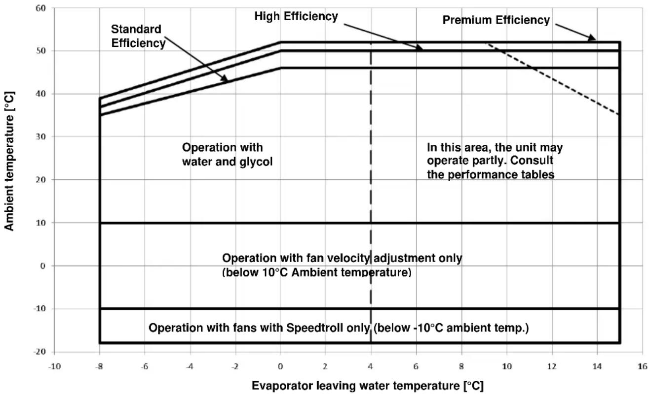
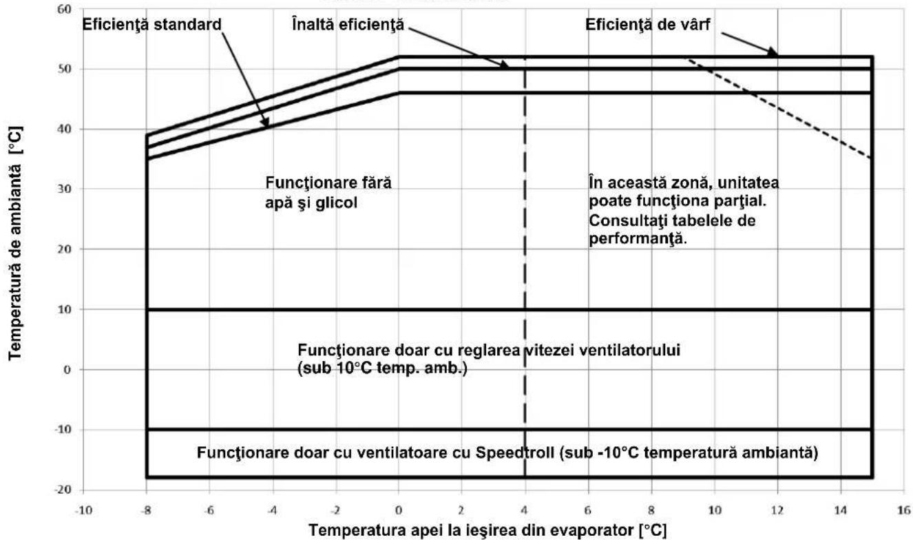
Operation
Operation is allowed within the limits mentioned in Figure 2. The unit must be operated with an evaporator water flow rate between 50% and 140% of nominal flow rate (at standard operating conditions).
Operation out of the mentioned limits may damage the unit. In case of doubts contact manufacturer representative.
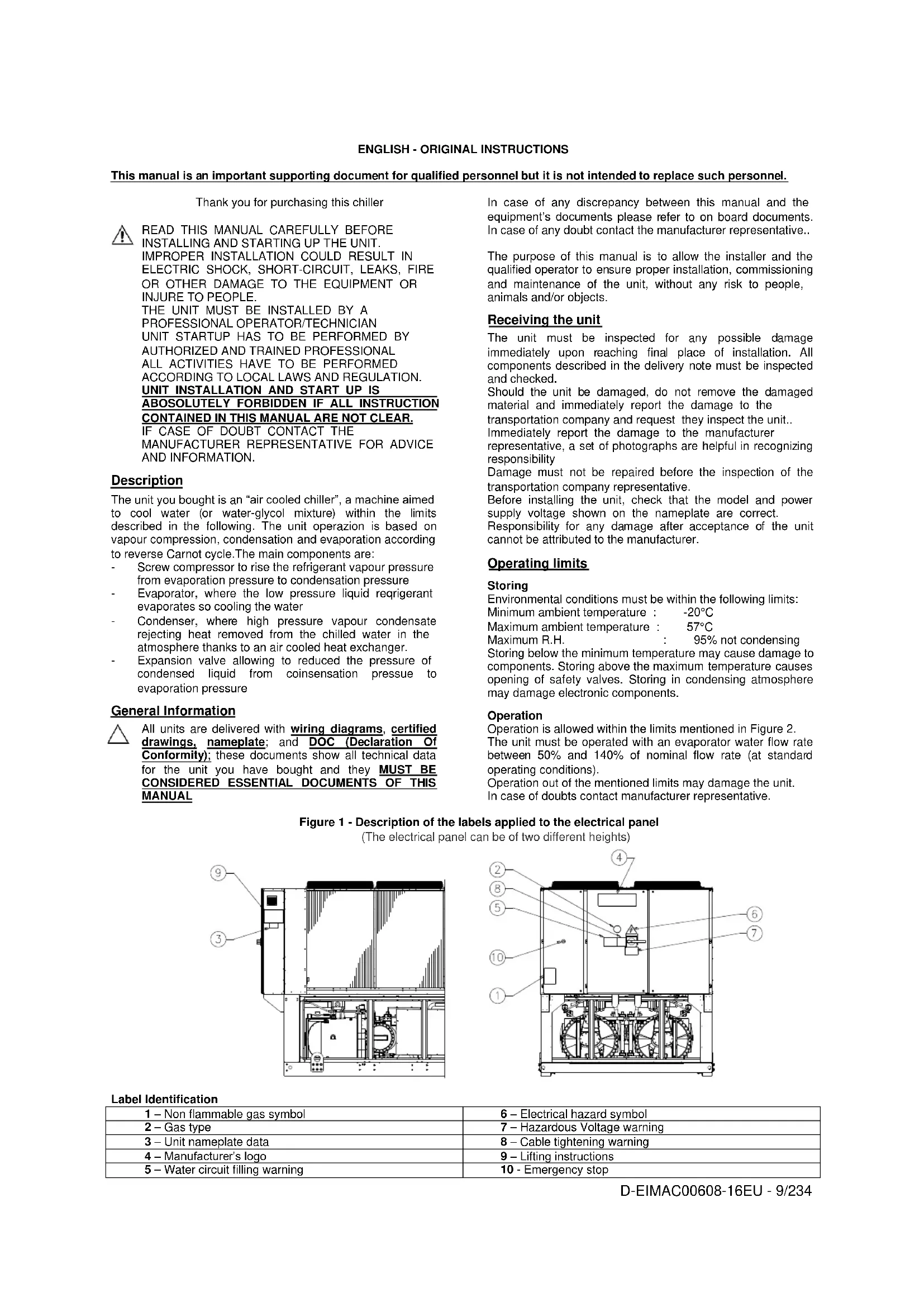
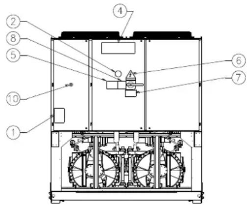
Figure 1 - Description of the labels applied to the electrical panel
(The electrical panel can be of two different heights)
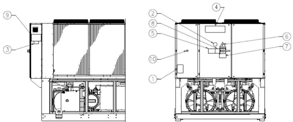
Label Identification
| 1 – Non flammable gas symbol | 6 – Electrical hazard symbol |
| 2 – Gas type | 7 – Hazardous Voltage warning |
| 3 – Unit nameplate data | 8 – Cable tightening warning |
| 4 – Manufacturer's logo | 9 – Lifting instructions |
| 5 – Water circuit filling warning | 10 - Emergency stop |
Figure 2 - Operating limits
line
| Evaporator leaving water temperature [°C] | Standard Efficiency [°C] | High Efficiency [°C] | Premium Efficiency [°C] | | ----------------------------------------- | ------------------------ | -------------------- | ----------------------- | | -8 | 38 | 39 | 37 | | -6 | 40 | 42 | 39 | | -4 | 42 | 45 | 41 | | -2 | 44 | 47 | 43 | | 0 | 46 | 50 | 45 | | 2 | 46 | 50 | 45 | | 4 | 46 | 50 | 45 | | 6 | 46 | 50 | 45 | | 8 | 46 | 50 | 45 | | 10 | 46 | 50 | 45 | | 12 | 46 | 50 | 45 | | 14 | 46 | 50 | 45 | | 16 | 46 | 50 | 45 |Safety
The unit must be firmly secured to the soil.
It is essential to observe the following instructions:
- The unit can only be lifted using the lifting points marked in yellow fixed to its base.
- It is forbidden to access the electrical components without having opened the unit main switch and switched off the power supply.
- It is forbidden to access the electrical components without using an insulating platform. Do not access the electrical components if water and/or moisture are present.
- Sharp edges and the surface of the condenser section could cause injury. Avoid direct contact and use adequate protection device
- Switch off power supply, by opening the main switch, before servicing the cooling fans and/or compressors. Failure to observe this rule could result in serious personal injury.
- Do not introduce solid objects into the water pipes while the unit is connected to the system.
- A mechanical filter must be installed on the water pipe connected to the heat exchanger inlet.
- The unit is supplied with safety valves, that are installed both on the high-pressure and on the low-pressure sides of the refrigerant circuit.
It is absolutely forbidden to remove all protections of moving parts.
In case of sudden stop of the unit, follow the instructions on the Control Panel Operating Manual which is part of the onboard documentation delivered to the end user.
It is strongly recommended to perform installation and maintenance with other people. In case of accidental injury or unease, it is necessary to:
- keep calm
-
press the alarm button if present in the installation site
-
move the injured person in a warm place far from the unit and in rest position
- contact immediately emergency rescue personnel of the building or the Health Emergency Service
- wait without leaving the injured person alone until the rescue operators come
- give all necessary information to the rescue operators

Avoid installing the chiller in areas that could be dangerous during maintenance operations, such as platforms without parapets or railings or areas not complying with the clearance requirements around the chiller.
Noise
The unit is a source of noise mainly due to rotation of compressors and fans.
The noise level for each model size is listed in sales documentation.
If the unit is correctly installed, operated and manteined the noise emission level do not require any special protection device to operate continuously close to the unit without any risk. In case of installation with special noise requirements it could be necessary to install additional sound attenuation devices.
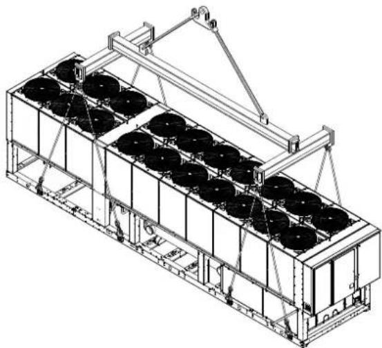
Moving and lifting
Avoid bumping and/or jolting during loading/unloading unit from the truck and moving it. Do not push or pull the unit from any part other than the base frame. Secure the unit inside the truck to prevent it from moving and causing damages. Do not allow any part of the unit to fall during transportation or loading/unloading.
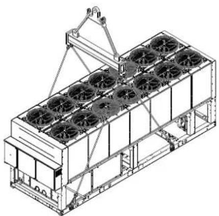
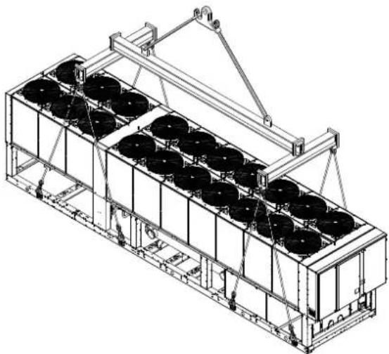
All units of the series are supplied with lifting points marked in yellow. Only these points may be used for lifting the unit, as shown in the following.
Use spacing bars to prevent damage to the condensation bank. Position these above the fan grills at a distance of at least 2.5 metres.

Both the lifting ropes and the spacing bars must be strong enough to support the unit safely. Please check the unit's weight on the unit nameplate.
The unit must be lifted with the utmost attention and care following lifting label instructions; lift unit very slowly, keeping it perfectly level..
Positioning and assembly
All units are designed for installation outdoors, either on balconies or on the ground, provided that the installation area is free of obstacles that could reduce air flow to the condensers coil.
The unit must be installed on a robust and perfectly level foundation; should the unit be installed on balconies or roofs, it might be necessary to use weight distribution beams.
Figure 3 - Lifting the unit
natural_image
Technical line drawing of a multi-level industrial cooling unit with fans and cooling tower (no text or symbols)2 compressors unit
For installation on the ground, a strong concrete base, at least 250 mm thickness and wider than the unit must be provided.
This base must be able to support the weight of the unit. If the uni is installed in places that are easily accessible to people and animals, it is advisable to install protection grids for the condenser and compressor sections.
To ensure best performance on the installation site, the following precautions and instructions must be followed:
- Avoid air flow recirculation.
- Make sure that there are no obstacles to hamper air flow.
- Make sure to provide a strong and solid foundation to reduce noise and vibrations.
- Avoid installation in particularly dusty environments, in order to reduce soiling of condensers coils.
- The water in the system must be particularly clean and all traces of oil and rust must be removed. A mechanical water filter must be installed on the unit's inlet piping.
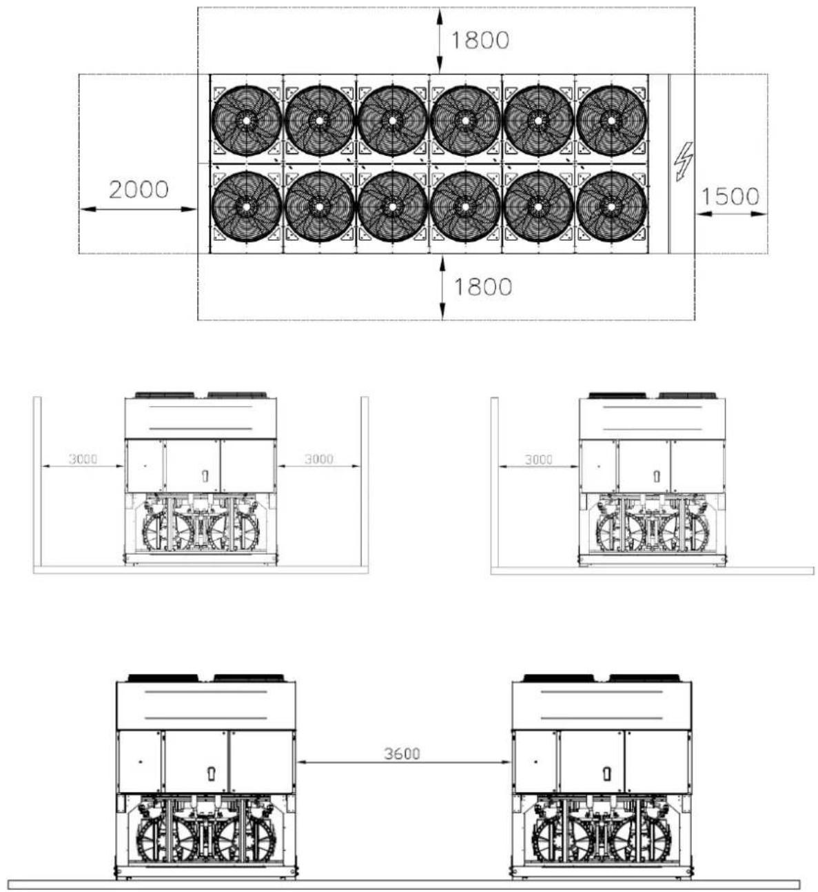
Minimum space requirements
It is fundamental to respect minimum distances on all units in order to ensure optimum ventilation to the condenser coils. When deciding where to position the unit and to ensure a proper air flow, the following factors must be taken into consideration:
- avoid any warm air recirculation
- avoid insufficient air supply to the air-cooled condenser.
Both these conditions can cause an increase of condensing pressure, which leads to a reduction in energy efficiency and refrigerating capacity.
Any side of the unit must be accessible for post-installation maintenance operations. Figure 3 shows the minimum space required.
Vertical air discharge must not be obstructed.
If the unit is surrounded by walls or obstacles of the same height as the unit, this must be installed at a distance no lower than 2500 mm. If these obstacles are higher, the unit must be installed at a distance no lower than 3000 mm.
Should the unit be installed without observing the recommended minimum distances from walls and/or vertical obstacles, there could be a combination of warm air
natural_image
Isometric line drawing of a multi-level industrial container with circular coils and a crane lifting a larger vessel (no text or symbols)3 compressors unit
recirculation and/or insufficient supply to the air-cooled condenser which could cause a reduction of capacity and efficiency.
In any case, the microprocessor will allow the unit to adapt itself to new operating conditions and deliver the maximum available capacity under any given circumstances, even if the lateral distance is lower than recommended, unless the operating conditions should affect personnel safety or unit reliability.
When two or more units are positioned side by side, a distance of at least 3600 mm between condenser banks is recommended.
For further solutions, please consult manufacturer representative.
Sound protection
When sound levels require special control, great care must be exercised to isolate the unit from its base by appropriately applying anti-vibration elements (supplied as an option).
Flexible joints must be installed on the water connections, as well.
Water piping
Piping must be designed with the lowest number of elbows and the lowest number of vertical changes of direction. In this way, installation costs are reduced considerably and system performance is improved.
The water system must have:
- Anti-vibration mountings in order to reduce transmission of vibrations to the structures.
- Isolating valves to isolate the unit from the water system during maintenance.
- Flow switch.
- Manual or automatic air venting device at the system's highest point.; drain device at the system's lowest point.
- Neither the evaporator nor the heat recovery device must be positioned at the system's highest point.
- A suitable device that can maintain the water system under pressure (expansion tank, etc.).
- Water temperature and pressure indicators to assist the operator during service and maintenance.
Figure 4 - Minimum clearance requirements
- A filter or device that can remove particles from the fluid. The use of a filter extends the life of the evaporator and pump and helps to keep the water system in a better condition.
- Evaporator has an electrical resistance with a thermostat that ensures protection against water freezing at ambient temperatures as low as -25^ . All the other water piping/devices outside the unit must therefore be protected against freezing.
-
The heat recovery device must be emptied of water during the winter season, unless an ethylene glycol mixture in appropriate percentage is added to the water circuit.
-
If case of unit substitution, the entire water system must be emptied and cleaned before the new unit is installed. Regular tests and proper chemical treatment of water are recommended before starting up the new unit.
- In the event that glycol is added to the water system as anti-freeze protection, pay attention to the fact that suction pressure will be lower, the unit's performance will be lower and water pressure drops will be greater. All unit-protection systems, such as anti-freeze, and low-pressure protection will need to be readjusted.
- Before insulating water piping, check that there are no leaks.
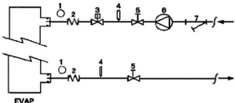
Figure 5 - Water piping connection for evaporator
flowchart
graph LR
    A["Component 1"] --> B["Component 2"]
    B --> C["Component 3"]
    C --> D["Component 4"]
    D --> E["Component 5"]
    E --> F["Component 6"]
    F --> G["Component 7"]
    G --> H["Output"]
    I["Component 1"] --> J["Component 2"]
    J --> K["Component 3"]
    K --> L["Component 4"]
    L --> M["Component 5"]
    M --> N["Component 6"]
    N --> O["Output"]
- Pressure Gauge
- Flexible connector
- Flow switch
-
Temperature probe
-
Isolation Valve
- Pump
- Filter
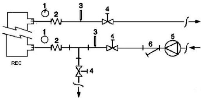
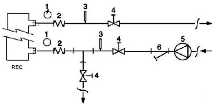
Figure 6 - Water piping connection for heat recovery exchangers
flowchart
graph TD
    REC --> 1["Resistor 1"]
    REC --> 2["Resistor 2"]
    1 --> 3["Capacitor 3"]
    2 --> 4["Capacitor 4"]
    3 --> 5["Diode 5"]
    4 --> 6["Switch 6"]
    5 --> f["Output f"]
    REC --> 7["Resistor 7"]
    7 --> 4
    4 --> 8["Diode 8"]
    8 --> f
    style REC fill:#f9f,stroke:#333
    style f fill:#ccf,stroke:#333
- Pressure Gauge
- Flexible connector
-
Temperature probe
-
Isolation Valve
- Pump
- Filter
Water treatment
Before putting the unit into operation, clean the water circuit. Dirt, scales, corrosion debris and other other material can accumulate inside the heat exchanger and reduce its heat exchanging capacity. Pressure drop can increase as well, thus reducing water flow. Proper water treatment therefore reduces
the risk of corrosion, erosion, scaling, etc. The most appropriate water treatment must be determined locally, according to the type of system and water characteristics. The manufacturer is not responsible for damage to or malfunctioning of equipment caused by failure to treat water or by improperly treated water.
Table 1 - Acceptable water quality limits
| pH (25°C) | 6,8÷8,0 | Total Hardness (mg CaCO_3 /l) | < 200 | |
| Electrical conductivity μS/cm (25°C) | <800 | Iron (mg Fe / l) | < 1.0 | |
| Chloride ion (mg Cl^- /l) | <200 | Sulphide ion (mg S^2^- /l) | None | |
| Sulphate ion (mg SO_4^2- /l) | <200 | Ammonium ion (mg NH_4^+ /l) | < 1.0 | |
| Alkalinity (mg CaCO_3 /l) | <100 | Silica (mg SiO_2 /l) | < 50 |
Evaporator and recovery exchangers anti-freeze protection
All evaporators are supplied with a thermostatically controlled anti-freeze electrical resistance, which provides adequate anti-freeze protection at temperatures as low as -25^ . However, unless the heat exchangers are completely empty and cleaned with anti-freeze solution, additional methods should also be used against freezing.
Two or more of below protection methods should be considered when designing the system as a whole:
Continuous water flow circulation inside piping and exchangers
– Addition of an appropriate amount of glycol inside the water circuit
– Additional heat insulation and heating of exposed piping
– Emptying and cleaning of the heat exchanger during the winter season
It is the responsibility of the installer and/or of local maintenance personnel to ensure that described anti-freeze methods are used. Make sure that appropriate anti-freeze protection is maintained at all times. Failing to follow the instructions above could result in unit damage. Damage caused by freezing is not covered by the warranty.
Installing the flow switch
To ensure sufficient water flow through the evaporator, it is essential that a flow switch be installed on the water circuit. The flow switch can be installed either on the inlet or outlet water piping. The purpose of the flow switch is to stop the unit in the event of interrupted water flow, thus protecting the evaporator from freezing.
The manufacturer offers, as optional, a flow switch that has been selected for this purpose.
This paddle-type flow switch is suitable for heavy-duty outdoor applications (IP67) and pipe diameters in the range of 1" to 6". The flow switch is provided with a clean contact which must be electrically connected to terminals shown in the wiring diagram.
Flow switch has to be tune to intervene when the evaporator water flow is lower than 50% of nomila flow rate.
Heat recovery
Units may be optionally equipped with heat recovery system. This system in made by a water cooled heat exchanger located on the compressors discharge pipe and a dedicated management of condensing pressure.
To guarantee compressor operation within its envelope, units with heat recovery cannot operate with water temperature of the heat recovery water lower than 28^ C.
It is a responsibility of plant designer and chiller installer to grantee the respect of this value (e.g. using recirculating bypass valve)
Electrical Installation
General specifications

All electrical connections to the unit must be carried out in compliance with laws and regulations in force.
All installation, management and maintenance activities must be carried out by qualified personnel. Refer to the specific wiring diagram for the unit you have bought. Should the wiring diagram not be on the unit or should it have been lost, please contact your manufacturer representative, who will send you a copy. In case of discrepancy between wiring diagram and electrical panel/cables please contact the manufacturer representative.
Only use copper conductors. Failure to use copper conductors could result in overheating or corrosion at connection points and could damage the unit.
To avoid interference, all control wires must be connected separately from the power cables. Use different electrical passage ducts for this purpose.
Before servicing the unit in any way, open the general disconnecting switch on the unit's main power supply.
When the unit is off but the disconnecting switch is in the closed position, unused circuits are live, as well.
Never open the terminal board box of the compressors before having opened the unit's general disconnecting switch.
Contemporaneity of single-phase and three-phase loads and unbalance between phases could cause leakages towards ground up to 150mA, during the normal operation of the units of the series.
If the unit includes devices that cause superior harmonics (like VFD and phase cut), the leakage towards ground could increase to very higher values (about 2 Ampere).
The protections for the power supply system have to be designed according to the above mentioned values.
Operation
Operator's responsibilities
It is essential that the operator is appropriately trained and becomes familiar with the system before operating the unit. In addition to reading this manual, the operator must study the microprocessor operating manual and the wiring diagram in order to understand start-up sequence, operation, shutdown sequence and operation of all the safety devices.
During the unit's initial start-up phase, a technician authorized by the manufacturer is available to answer any questions and to give instructions as to the correct operating procedures.
The operator must keep a record of operating data for every installed unit. Another record should also be kept of all the periodical maintenance and servicing activities.
If the operator notes abnormal or unusual operating conditions, he is advised to consult the technical service authorized by the manufacturer.
Routine maintenance
Minimum maintenance activities are listed in Table 2
Service and limited warranty
All units are factory-tested and guaranteed for 12 months as of the first start-up or 18 months as of delivery.
These units have been developed and constructed according to high quality standards ensuring years of failure-free operation. It is important, however, to ensure proper and periodical maintenance in accordance with all the procedures listed in this manual and with good practice of machines maintenance.
We strongly advise stipulating a maintenance contract with a service authorized by the manufacturer in order to ensure efficient and problem-free service, thanks to the expertise and experience of our personnel.
It must also be taken into consideration that the unit requires maintenance also during the warranty period.
It must be borne in mind that operating the unit in an inappropriate manner, beyond its operating limits or not performing proper maintenance according to this manual can void the warranty.
Observe the following points in particular, in order to conform to warranty limits:
- The unit cannot function beyond the specified limits
- The electrical power supply must be within the voltage limits and without voltage harmonics or sudden changes.
- The three-phase power supply must not have un balance between phases exceeding 3%. The unit must stay turned off until the electrical problem has been solved.
- No safety device, either mechanical, electrical or electronic must be disabled or overridden.
- The water used for filling the water circuit must be clean and suitably treated. A mechanical filter must be installed at the point closest to the evaporator inlet.
- Unless there is a specific agreement at the time of ordering, the evaporator water flow rate must never be above 120% and below 80% of the nominal flow rate.
Periodic obligatory checks and starting up of appliances under pressure
The units are included in category IV of the classification established by the European Directive PED2014/68EU.
For chillers belonging to this category, some local regulations require a periodic inspection by an authorized agency. Please check with your local requirements.
Table 2 - Routine maintenance programme
| List of Activities | Weekly | Monthly (Note 1) | Yearly/Seasonal (Note 2) |
| General: | |||
| Reading of operating data (Note 3) | X | ||
| Visual inspection of unit for any damage and/or loosening | X | ||
| Verification of thermal insulation integrity | X | ||
| Clean and paint where necessary | X | ||
| Analysis of water (6) | X | ||
| Check of flow switch operation | X | ||
| Electrical: | |||
| Verification of control sequence | X | ||
| Verify contactor wear – Replace if necessary | X | ||
| Verify that all electrical terminals are tight – Tighten if necessary | X | ||
| Clean inside the electrical control board | X | ||
| Visual inspection of components for any signs of overheating | X | ||
| Verify operation of compressor and electrical resistance | X | ||
| Measure compressor motor insulation using the Megger | X | ||
| Refrigeration circuit: | |||
| Check for any refrigerant leakage | X | ||
| Verify refrigerant flow using the liquid sight glass – Sight glass full | X | ||
| Verify filter dryer pressure drop | X | ||
| Verify oil filter pressure drop (Note 5) | X | ||
| Analyse compressor vibrations | X | ||
| Analyse compressor oil acidity (7) | X | ||
| Condenser section: | |||
| Clean condenser banks (Note 4) | X | ||
| Verify that fans are well tightened | X | ||
| Verify condenser bank fins – Comb if necessary | X |
Notes:
1. Monthly activities include all the weekly ones.
2. The annual (or early season) activities include all weekly and monthly activities.
3. Unit operating values should be read on a daily basis thus keeping high observation standards.
4. In environments with a high concentration of air-borne particles, it might be necessary to clean the condenser bank more often.
5. Replace the oil filter when the pressure drop across it reaches 2.0 bar.
6. Check for any dissolved metals.
7. TAN (Total Acid Number) : ≤0,10 : No action
Between 0.10 and 0.19 : Replace anti-acid filters and re-check after 1000 running hours. Continue to replace filters until the TAN is lower than 0.10.
0,19 : Replace oil, oil filter and filter dryer. Verify at regular intervals.
Important information regarding the refrigerant used
This product contains fluorinated greenhouse gases. Do not vent gases into the atmosphere.
Refrigerant type: R134a
GWP(1) value: 1430
(1)GWP = Global Warming Potential
The refrigerant quantity necessary for standard operation is indicated on the unit name plate.
Real refrigerant quantity charged in the unit is listed on a silver sticker inside the electrical panel.
Periodical inspections for refrigerant leaks may be required depending on European or local legislation.
Please contact your local dealer for more information.
Factory and Field charged units instructions
(Important information regarding the refrigerant used)
The refrigerant system will be charged with fluorinated greenhouse gases.
Do not vent gases into the atmosphere.
1 Fill in with indelible ink the refrigerant charge label supplied with the product as following instructions:
- the refrigerant charge for each circuit (1; 2; 3)
- the total refrigerant charge (1 + 2 + 3)
- calculate the greenhouse gas emission with the following formula:
GWP value of the refrigerant x Total refrigerant charge (in kg) / 1000

a Contains fluorinated greenhouse gases
b Circuit number
c Factory charge
d Field charge
e Refrigerant charge for each circuit (according to the number of circuits)
f Total refrigerant charge
g Total refrigerant charge (Factory + Field)
h Greenhouse gas emission of the total refrigerant charge expressed as tonnes of CO2 equivalent
m Refrigerant type
n GWP = Global Warming Potential
p Unit serial number
2 The filled out label must be adhered inside the electrical panel.
Periodical inspections for refrigerant leaks may be required depending on European or local legislation. Please contact your local dealer for more information.
NOTICE
In Europe, the greenhouse gas emission of the total refrigerant charge in the system
(expressed as tonnes CO_2 equivalent) is used to determine the maintenance intervals.
Follow the applicable legislation.
Formula to calculate the greenhouse gas emission:
GWP value of the refrigerant x Total refrigerant charge (in kg) / 1000
Use the GWP value mentioned on the greenhouse gases label. This GWP value is
based on the 4th IPCC Assessment Report. The GWP value mentioned in the manual might be outdated (i.e. based on the 3rd IPCC Assessment Report)
Disposal
The unit is made of metal, plastic and electronic parts. All these parts must be disposed of in accordance with the local regulations in terms of disposal.
Lead batteries must be collected and sent to specific refuse collection centres.
Oil must be collected and sent to specific refuse collection centres.
This manual is a technical aid and does not represent a binding offer. The content cannot be held as explicitly or implicitly guaranteed as complete, precise or reliable. All data and specifications contained herein may be modified without notice. The data communicated at the moment of the order shall hold firm.
The manufacturer shall assume no liability whatsoever for any direct or indirect damage, in the widest sense of the term, ensuing from or connected with the use and/or interpretation of this manual.
We reserve the right to make changes in design and construction at any time without notice, thus the cover picture is not binding.
Freecooling Unit Version
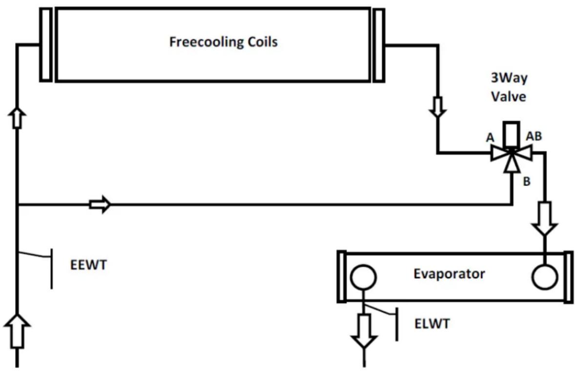
Freecooling units have additional coils used to pre-cool the fluid coming from the building and increase the overall efficiency by unloading the compressors until their completely stop if the environments conditions allow it. The water flow can be diverted to the additional coils in case the outside ambient temperature drops below the return water temperature by three way valve (or two single way valves. It depends from chiller size).
Freecooling operation can be enable by QFC switch installed in the control section of the electrical panel. Once the Freecooling function is enabled, the unit controller manages automatically the operation of the water valves. The system controls, also, the operation of fans maximizing the freecooling effect.
ATTENTION
The water system MUST be filled with the proper percentage of Water and Glycol. It is responsibility of end user to ensure to appropriate amount of Water/Glycol percentage. Damage of Freecooling coils caused by freezing is not covered by the warranty.
ATTENTION
Install field-provided flow switches with water pump interlock to sense the system water flow.
ATTENTION
To prevent damage to the freecooling coils and evaporator tubes, install a strainer in the unit water inlet piping. Strainer must have maximum 0,5 mm mesh.
There are two types of freecooling control system:
Freecooling system with 3 Way Valve
EWAD640CF-XS/XL ÷ EWADC11CF-XS/XL - EWAD600CF-XR ÷ EWADC10CF-XR
flowchart
graph TD
    A["Freecooling Coils"] --> B["3Way Valve"]
    B --> C["A"]
    B --> D["AB"]
    B --> E["B"]
    C --> F["Evaporator"]
    D --> F
    E --> F
    G["EEWT"] --> A
    H["ELWT"] --> I["End"]
EEWT = Water entering temperature probe ELWT = Water leaving temperature probe
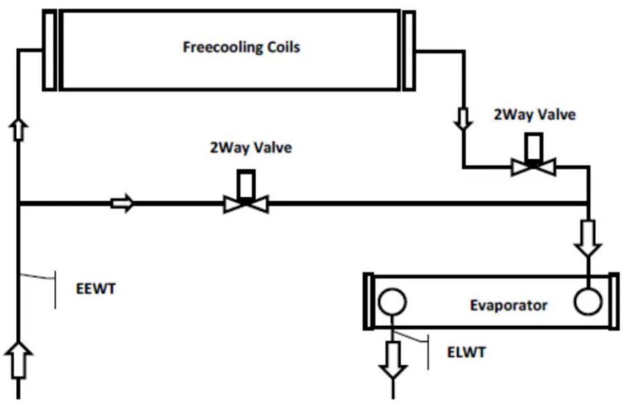
Freecooling system with 2 Way valves
EWADC12CF-XS/XL ÷ EWADC16CF-XS/XL - EWADC11CF-XR ÷ EWADC15CF-XR
flowchart
graph TD
    A["Freecooling Coils"] --> B["2Way Valve"]
    B --> C["2Way Valve"]
    C --> D["Evaporator"]
    D --> E["ELWT"]
    D --> F["EEWT"]
    F --> G["Top Flow"]
EEWT = Water entering temperature probe ELWT = Water leaving temperature probe
System change over is controlled by embedded unit controller, depending from operating conditions and unit setpoint. Between winter and summer operation the water side pressure drops are different, consequently the chiller water flow could be different. Evaluate that the minimum and maximum water flow, between summer and winter operation, are inside the water flow limits (see product manual).
natural_image
Technical line drawing of a multi-level industrial cooling unit with fans and cooling tower (no text or symbols)natural_image
Technical line drawing of a multi-level industrial container with circular components and overhead crane (no text or symbols)(1) GWP = Global Warming Potential (Treibhauspotential)
n GWP = Global warming potential (Treibhauspotential)
natural_image
Technical line drawing of a multi-level industrial cooling unit with fans and cooling tower (no text or symbols)natural_image
Technical line drawing of a multi-level industrial container with circular components and overhead crane (no text or symbols)Figure 6 - Water piping connection for heat recovery exchangers
flowchart
graph TD
    A["REC"] --> B["1"]
    A --> C["2"]
    B --> D["3"]
    C --> E["4"]
    D --> F["5"]
    E --> G["6"]
    G --> H["7"]
    H --> I["8"]
    I --> J["9"]
    J --> K["10"]
    K --> L["11"]
    L --> M["12"]
    M --> N["13"]
    N --> O["14"]
    O --> P["15"]
    P --> Q["16"]
    Q --> R["17"]
    R --> S["18"]
    S --> T["19"]
    T --> U["20"]
natural_image
Technical line drawing of a multi-level industrial cooling unit with fans and cooling tower (no text or symbols)natural_image
Technical line drawing of a multi-level industrial container with circular components and a crane lifting a larger vessel (no text or symbols visible)natural_image
Technical line drawing of a multi-level industrial cooling unit with fans and cooling tower (no text or symbols)natural_image
Technical line drawing of a multi-level industrial container with circular components and a crane hook (no text or symbols)natural_image
Technical line drawings of two industrial cooling units with fans and heat sinks (no text or symbols)natural_image
Technical line drawing of a multi-level industrial cooling unit with fans and cooling tower (no text or symbols)2 μονάδες συμπιεστή

natural_image
Technical line drawing of a multi-level industrial container with circular components and overhead crane (no text or symbols)3 μονάδες συμπιεστή
natural_image
Technical line drawing of a multi-level industrial cooling unit with fans and cooling fans (no text or symbols)natural_image
Technical line drawing of a multi-level industrial container with circular coils and a crane lifting a larger vessel (no text or symbols)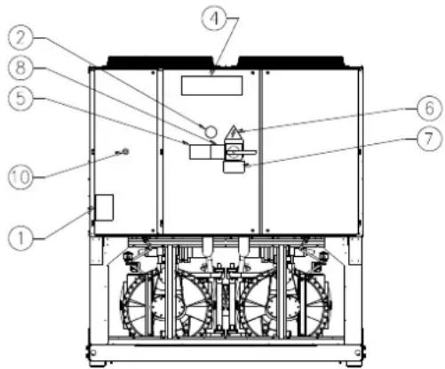
natural_image
Technical line drawing of a multi-level industrial cooling unit with fans and cooling fans (no text or symbols)natural_image
Technical line drawing of a multi-level industrial container with circular components and a crane lifting a larger vessel (no text or symbols)natural_image
Technical line drawing of a multi-level industrial cooling unit with fans and cooling tower (no text or symbols)2 kompressorenhet
natural_image
Isometric line drawing of a multi-level industrial container with circular coils and a crane (no text or symbols)3 kompressorenhet
Installing the flow switch
natural_image
Two technical line drawings of industrial cooling units with fans and heat sinks, no text or symbols present.a Inneholder fluorholdige klimagasser
b Kretsnummer
c Fabrikkfylt
d Feltfylt
Tarran tunnistus
natural_image
Technical line drawing of a multi-level industrial cooling unit with fans and cooling tower (no text or symbols)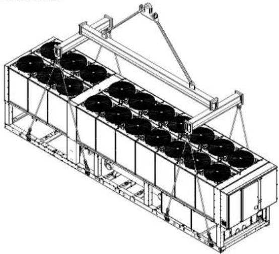
natural_image
Technical line drawing of a multi-level industrial container with circular components and a crane lifting a larger vessel (no text or symbols)Periodic obligatory checks and starting up of appliances under pressure
The units are included in category IV of the classification established by the European Directive PED 2014/68/EU.
For chillers belonging to this category, some local regulations require a periodic inspection by an authorized agency. Please
check with your local requirements.
natural_image
Technical line drawings of industrial cooling units with fans and heat sinks (no text or symbols)natural_image
Technical line drawing of a multi-level industrial cooling unit with fans and cooling tower (no text or symbols)2 kompreosrové jednotky

natural_image
Technical line drawing of a multi-level industrial container with circular components and overhead crane (no text or symbols)a Sadrži fluorirane stakleničke plinove
b Broj kruga
c Tvorničko punjenje
d Punjenje na terenu
Figura 2 – Limite operative
line
| Temperature | Functionare for a la iesirea din evaporator [°C] | Functionare doar cu ventilatoare cu Speedtroll [°C] | | ----------- | --------------------------------------------- | ------------------------------------------------ | | -8 | 38 | -10 | | -6 | 42 | -10 | | -4 | 46 | -10 | | -2 | 48 | -10 | | 0 | 50 | -10 | | 2 | 50 | -10 | | 4 | 50 | -10 | | 6 | 50 | -10 | | 8 | 50 | -10 | | 10 | 50 | -10 | | 12 | 50 | -10 | | 14 | 50 | -10 | | 16 | 50 | -10 |Sguranță
natural_image
Technical line drawing of a multi-level industrial cooling unit with fans and cooling tower (no text or symbols)natural_image
Technical line drawing of a multi-level industrial container with circular components and a crane lifting a larger portion (no text or symbols)natural_image
Technical line drawing of a multi-level industrial cooling unit with fans and cooling tower (no text or symbols)Enota z 2 kompresorjema

natural_image
Technical line drawing of a multi-level industrial container with circular components and a crane overhead (no text or symbols)Enota s 3 kompresorji
a Vsebuje fluorirane toplogredne pline
b Številka kroga
natural_image
Technical line drawing of a multi-level industrial cooling unit with fans and cooling fans (no text or symbols)natural_image
Technical line drawing of a multi-level industrial container with circular coils and a crane lifting a larger vessel (no text or symbols)natural_image
Technical line drawings of industrial cooling units with fans and heat sinks (no text or symbols)2 jednotka kompresora 3 jednotka kompresora
a Vsebuje fluorirane toplogredne pline
b Številka kroga
The present publication is drawn up by of information only and does not constitute an offer binding upon Daikin Applied Europe S.p.A.. Daikin Applied Europe S.p.A. has compiled the content of this publication to the best of its knowledge. No express or implied warranty is given for the completeness, accuracy, reliability or fitness for particular purpose of its content, and the products and services presented therein. Specification are subject to change without prior notice. Refer to the data communicated at the time of the order. Daikin Applied Europe S.p.A. explicitly rejects any liability for any direct or indirect damage, in the broadest sense, arising from or related to the use and/or interpretation of this publication. All content is copyrighted by Daikin Applied Europe S.p.A..