
VT55ST - Lighting V-TAC - Free user manual and instructions
Find the device manual for free VT55ST V-TAC in PDF.
| Product type | LED floodlight with adjustable angle |
| Brand | V-TAC |
| Model | VT55ST |
| Power | 50 W |
| Luminous flux | 4700 lm |
| Beam angle | 100° |
| Color Rendering Index (CRI) | ≥80 |
| Input voltage | AC 220-240 V, 50/60 Hz |
| Operating temperature | -20°C to +40°C |
| Lifespan | 30,000 hours |
| Switching cycles | 20,000 cycles |
| Protection rating | IP65 |
| Dimensions (L x W x H) | 412 x 139 x 92 mm |
| Net weight | 670 g |
| Housing material | Aluminum + PC |
| Mounting diameter | 60 mm |
| Mounting height | 3-5 m |
| Maximum projection area | 20-30 m² |
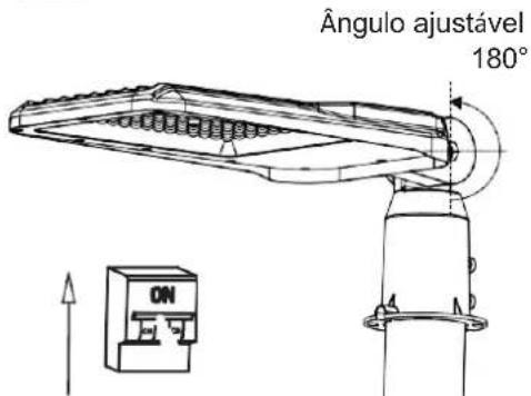
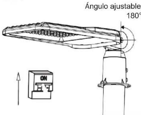
| Adjustable angle | 180° |
| Warranty | 5 years |
| Replaceable light source | No (replace entire luminaire at end of life) |
| Minimum distance from illuminated objects | 1 m |
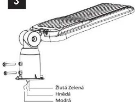
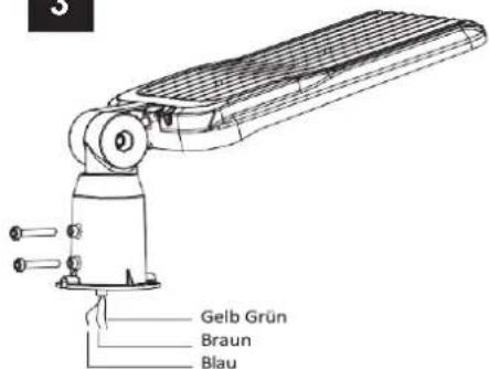
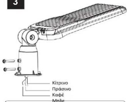
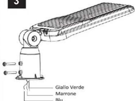
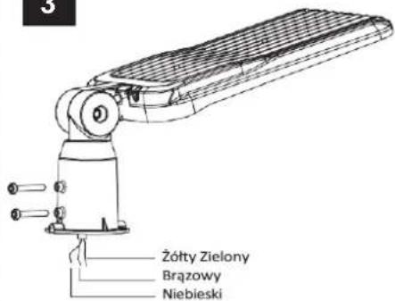
| Wire color | Brown (phase), Blue (neutral), Yellow/Green (ground) |
| Certifications | RoHS, CE |
Frequently Asked Questions - VT55ST V-TAC
User questions about VT55ST V-TAC
0 question about this device. Answer the ones you know or ask your own.
Ask a new question about this device
Download the instructions for your Lighting in PDF format for free! Find your manual VT55ST - V-TAC and take your electronic device back in hand. On this page are published all the documents necessary for the use of your device. VT55ST by V-TAC.
USER MANUAL VT55ST V-TAC
WEEE Number: 80133970
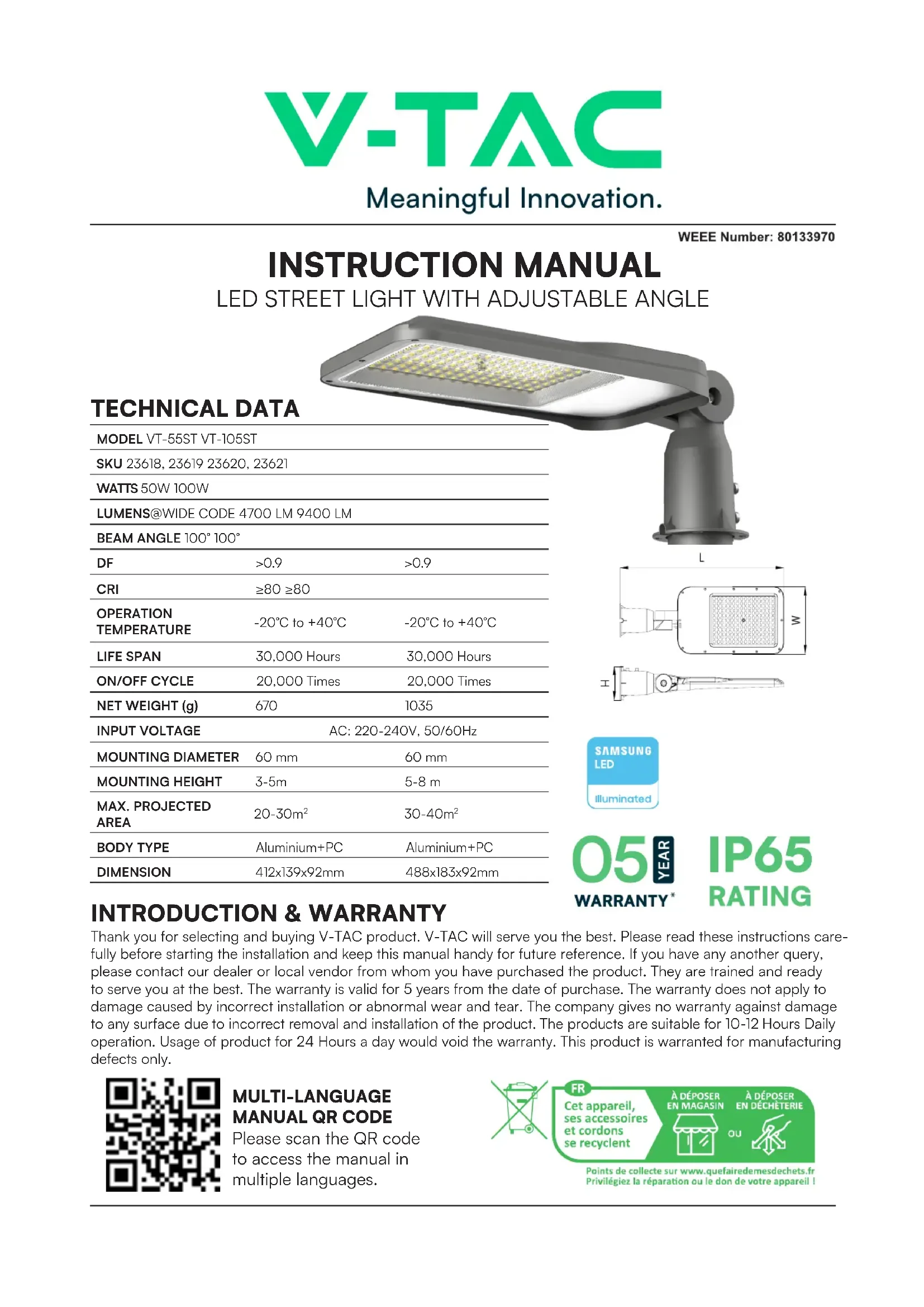
INSTRUCTION MANUAL
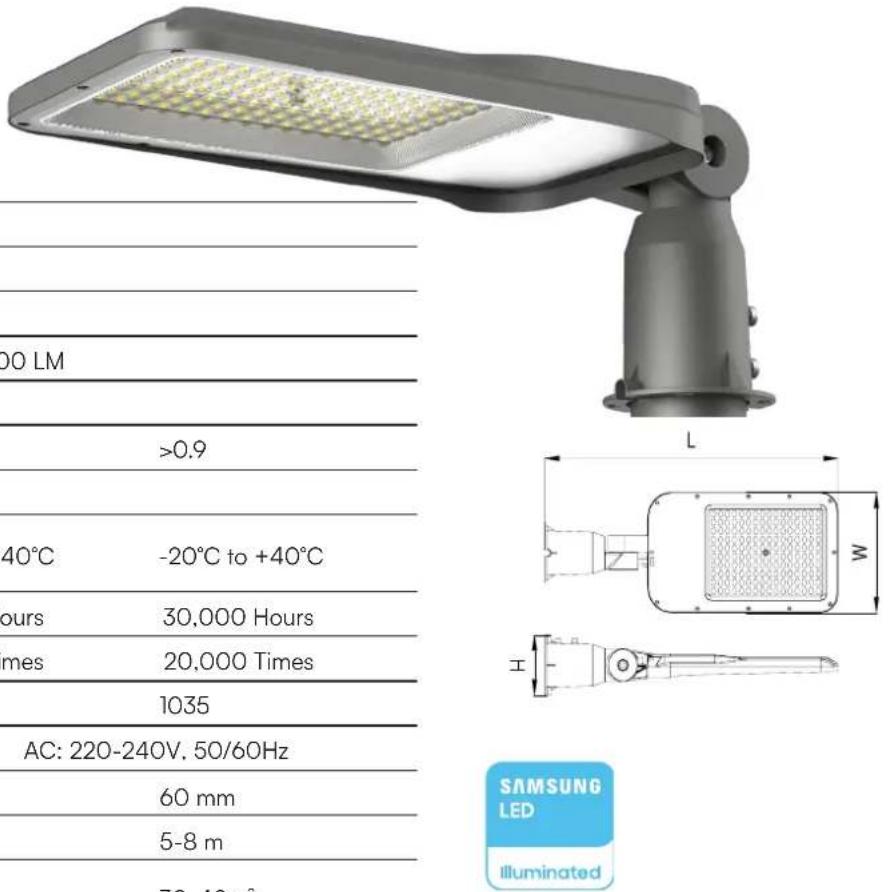
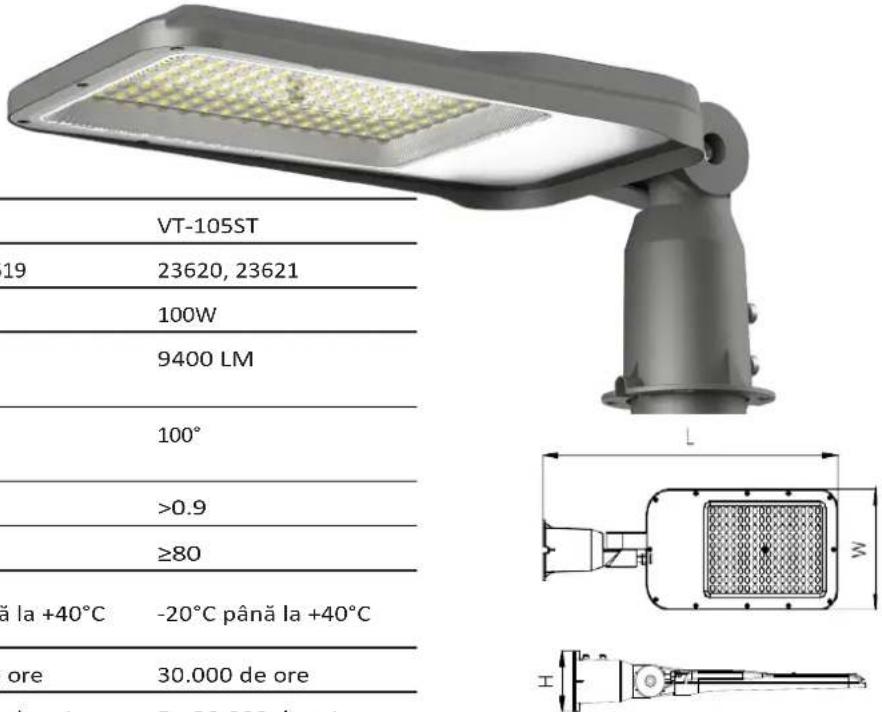
LED STREET LIGHT WITH ADJUSTABLE ANGLE
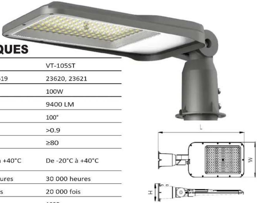
TECHNICAL DATA
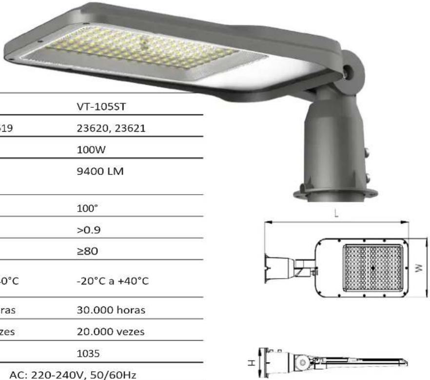
| MODEL VT-55ST VT-105ST | ||
| SKU 23618, 23619 23620, 23621 | ||
| WATTS 50W 100W | ||
| LUMENS@WIDE CODE 4700 LM 9400 LM | ||
| BEAM ANGLE 100° 100° | ||
| DF | >0.9 | >0.9 |
| CRI | ≥80 ≥80 | |
| OPERATION TEMPERATURE | -20°C to +40°C | -20°C to +40°C |
| LIFE SPAN | 30,000 Hours | 30,000 Hours |
| ON/OFF CYCLE | 20,000 Times | 20,000 Times |
| NET WEIGHT (g) | 670 | 1035 |
| INPUT VOLTAGE | AC: 220-240V, 50/60Hz | |
| MOUNTING DIAMETER | 60 mm | 60 mm |
| MOUNTING HEIGHT | 3-5m | 5-8 m |
| MAX. PROJECTED AREA | 20-30m2 | 30-40m2 |
| BODY TYPE | Aluminium+PC | Aluminium+PC |
| DIMENSION | 412x139x92mm | 488x183x92mm |
05 YEAR IP65 WARRANTY* RATING
INTRODUCTION & WARRANTY
Thank you for selecting and buying V-TAC product. V-TAC will serve you the best. Please read these instructions carefully before starting the installation and keep this manual handy for future reference. If you have any another query, please contact our dealer or local vendor from whom you have purchased the product. They are trained and ready to serve you at the best. The warranty is valid for 5 years from the date of purchase. The warranty does not apply to damage caused by incorrect installation or abnormal wear and tear. The company gives no warranty against damage to any surface due to incorrect removal and installation of the product. The products are suitable for 10-12 Hours Daily operation. Usage of product for 24 Hours a day would void the warranty. This product is warranted for manufacturing defects only.

MULTI-LANGUAGE MANUAL QR CODE
Please scan the QR code to access the manual in multiple languages.

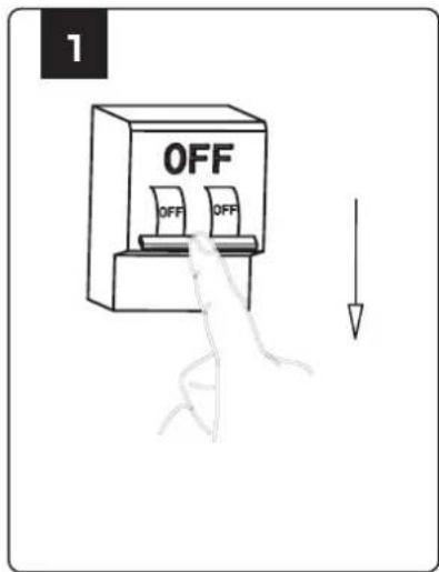
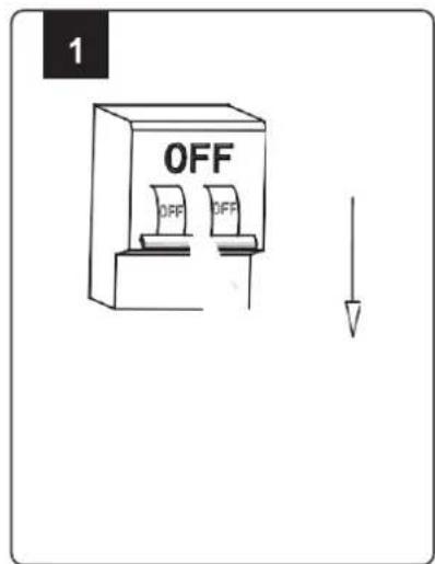
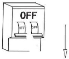
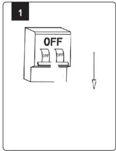
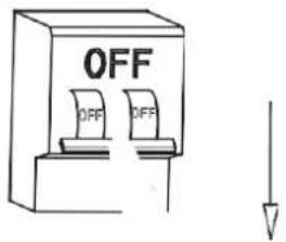
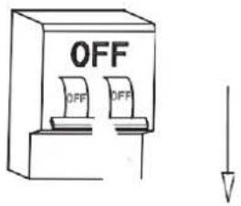
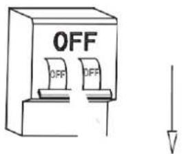
- Please make sure to turn off the power before starting the installation.
- Installation must be performed by a qualified electrician.
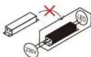
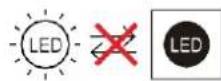
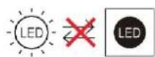
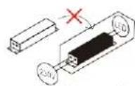
- The light source of this luminaire is not replaceable, when the light source reaches its end of life the whole luminaire should be replaced.
- If the external flexible cable or cord of this luminaire is damaged, it shall be exclusively replaced by the manufacturer or his service agent or a similar qualified person in order to avoid a hazard.
- Replace any cracked protective shield.
- Minimum distance from lighted objects 1m.
- Terminal block not included.
- Proper grounding should be ensured throughout the installation.


This marking indicates that this product should not be disposed of with other household wastes.

Caution, risk of electric shock.
INSTALLATION INSTRUCTIONS
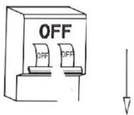
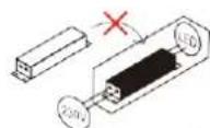
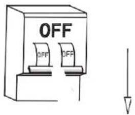
- Switch Off the power before starting the installation.
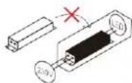
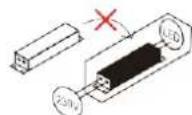
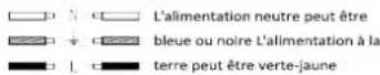
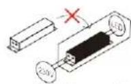
- Connect the wiring (brown wire to Live wire, the blue line to Neutral wire, yellow/green line to ground wire) to the luminaire as displayed in the wiring diagram. Please make sure to use 3 core power cord and ensure the ground wire must be grounded. (Outer wire size 250mm ±10mm)
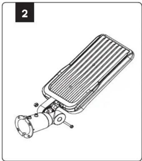
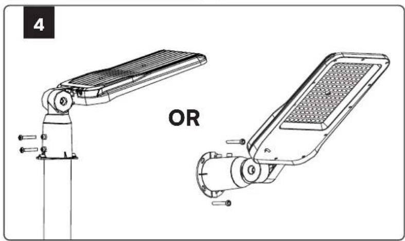
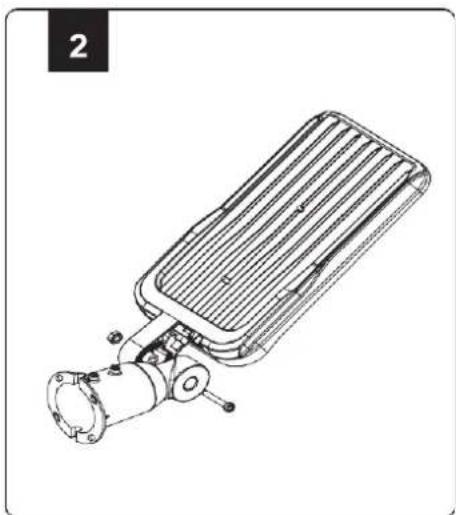
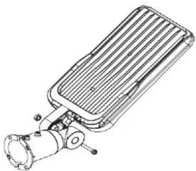
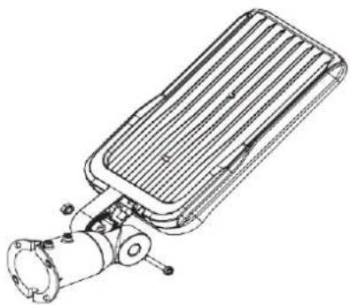
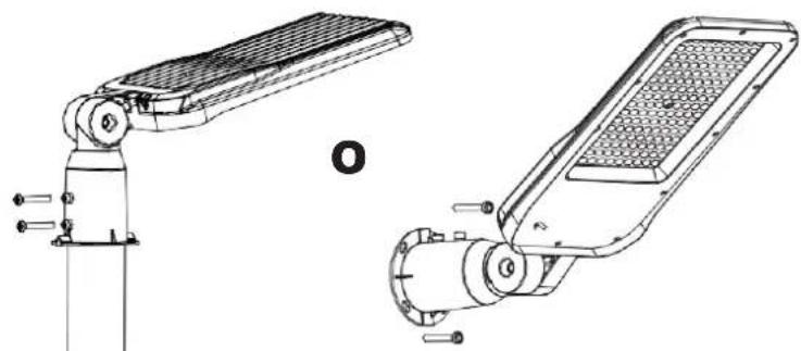
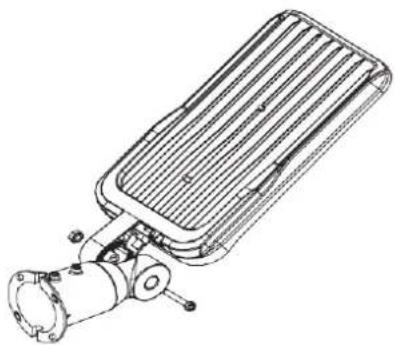
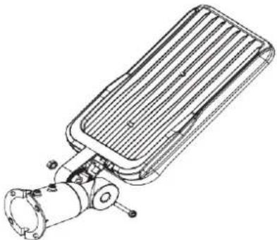
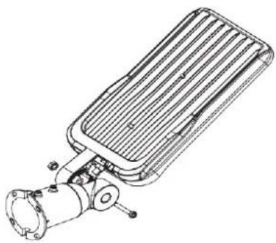
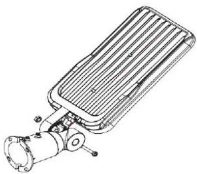
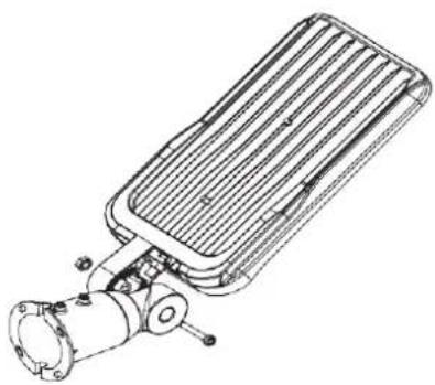
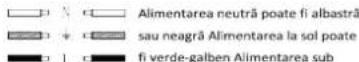
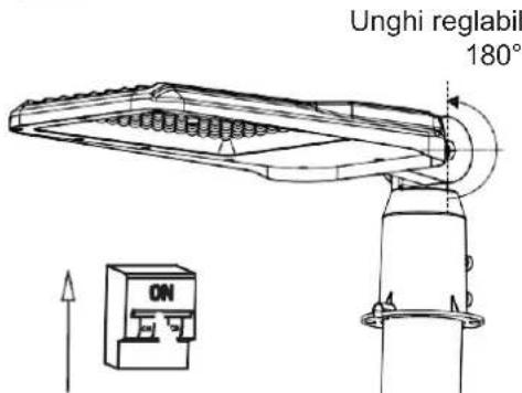
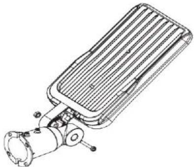
- Loosen the M6 screws using the screwdriver and install the streetlight on the pole. Then tighten the M6 screws and ensure the streetlight is properly installed on the pole. Or screw it directly to the wall.
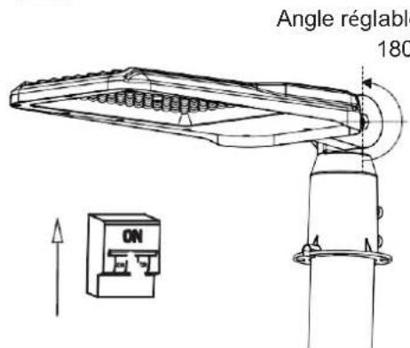
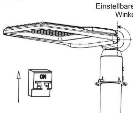
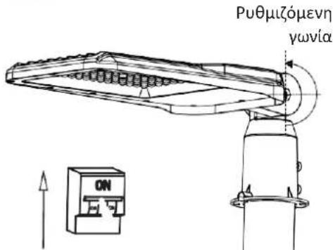
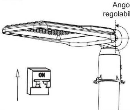
- Adjust the angle of the street light within a 180-degree range to suit your lighting needs.
- Switch On the power to test the light.

Non-replaceable light source
Non-replaceable control gear
natural_image
Technical line drawing of a mechanical component with a flanged base and pipe fitting (no text or symbols)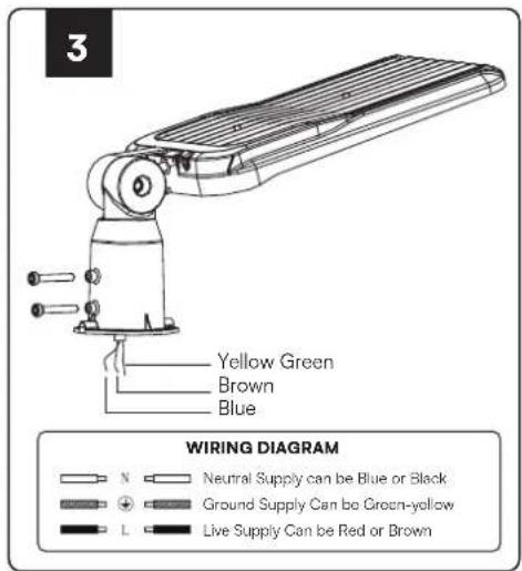
natural_image
Technical line drawing of two smart streetlights with labeled components (no text or symbols on the devices themselves)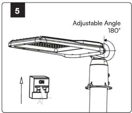
NOTE
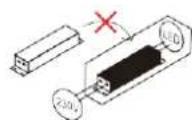
- Wiring instructions: The power should be connected to binding post inside the junction box, which IP grade should be higher than the Imap's IP grade. And the junction box should have fasten device for the wires. Inside terminal block shall conform to EN 60998-2-1 or EN 60998-2-2 (specification: three terminals, atleast 250V and 1.5mm2).
- User should prepare all the necessary accessories and spare parts (Spare parts not provided) including junction box.
- Inspect the lamps and lanterns before installation to ensure no damage or deformation.
- Protect the lamps and lanterns during installation and maintenance, ensure all fittings are fixed, connect the lamp body to the light pole using screws, and ensure the screw torque is less than 10.5 N.m.
- During maintenance and installation, ensure all parts are intact and replace any damaged or defective parts.
- The lamps and lanterns use a double insulated wire for the power cord, replace it with a professional if there's any breakage to avoid danger.
- It's normal for the lamps and lanterns surface to have a certain temperature when in use.
RoHS


РЪКОВОДСТВО ЗА УПОТРЕБА
natural_image
Technical line drawing of a mechanical device with a cylindrical component and ribbed housing (no text or symbols)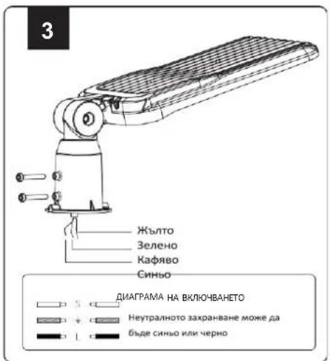
natural_image
Technical line drawings of two mechanical components, one with a flat panel and the other with a meshed device (no text or symbols)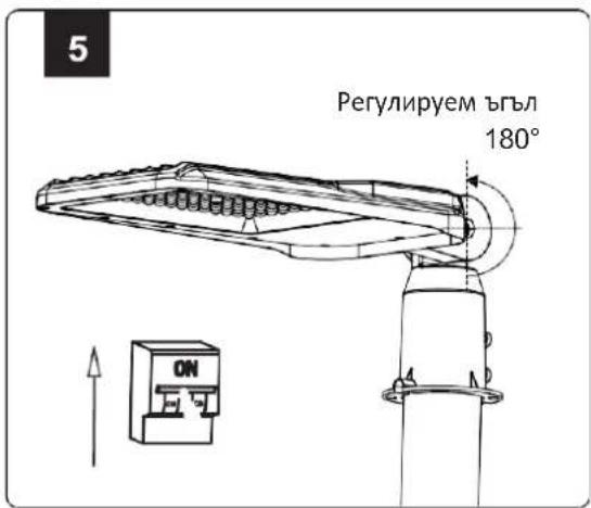
05 YEAR IP65 WARRANTY* RATING
ÚVOD A ZÁRUKA
Non-replaceable light source
Non-replaceable control gear
1
2
natural_image
Technical line drawing of a mechanical device with a rectangular housing and internal components (no text or symbols)3
natural_image
Technical line drawings of two industrial robotic devices, one with a flat blade and the other with a meshed sensor or panel (no text or symbols)5

MANUEL D'INSTRUCTIONS
LAMPADAIRE À LED AVEC ANGLE RÉGLABLE
DONNÉES TECHNIQUES
| MODÈLE | VT-55ST | VT-105ST |
| SKU | 23618, 23619 | 23620, 23621 |
| WATTS | 50W | 100W |
| LUMENS@CODE GLOBAL | 4700 LM | 9400 LM |
| ANGLE DU FAISCEAU | 100° | 100° |
| DF | >0.9 | >0.9 |
| CRI | ≥80 | ≥80 |
| TEMPÉRATURE DE FONCTIONNEMENT | De -20°C à +40°C | De -20°C à +40°C |
| DURÉE DEVIE | 30 000 heures | 30 000 heures |
| CYCLE MARCHE/ARRÊT | 20 000 fois | 20 000 fois |
| POIDS NET (g) | 670 | 1035 |
| TENSION D'ENTRÉE | AC : 220-240V, 50/60Hz | |
| DIAMÈTRE DE MONTAGE | 60 mm | 60 mm |
| HAUTEUR DE MONTAGE | 3-5m | 5-8 m |
| MAX. SURFACE PROJETÉE | 20-30m2 | 30-40m2 |
| TYPE DE CORPS | Aluminium+PC | Aluminium+PC |
| DIMENSION | 412x139x92mm | 488x183x92mm |

05 YEAR WARRANTY*
IP65 RATING
INTRODUCTION ET GARANTIE
Non-replaceable light source
Non-replaceable control gear
1

2
natural_image
Technical line drawing of a mechanical device with a cylindrical component and ribbed housing (no text or symbols)3
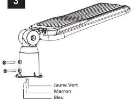
SCHÉMA DE CÂBLAGE
4
natural_image
Technical line drawings of two robotic devices, one with a vertical support and the other with a meshed device (no text or symbols)5
NOTE
Non-replaceable light source
Non-replaceable control gear
1
2
natural_image
Technical line drawing of a mechanical device with a cylindrical component and a rectangular housing (no text or symbols)3
natural_image
Technical line drawing of two robotic devices with labeled 'OR' (no text or symbols on the devices themselves)5
ANMERKUNG
Non-replaceable light source

Non-replaceable control gear
1
2

natural_image
Technical line drawing of a mechanical device with a rectangular housing and internal components (no text or symbols)3
ΔΙΑΓΡΑΜΜΑ ΣΥΝΔΕΣΗΣ
natural_image
Technical line drawings of two mechanical components, one with a vertical rod and labeled 'H', the other with a meshed device (no text or symbols present)5
Non-replaceable light source
Non-replaceable control gear

natural_image
Technical line drawing of a mechanical device with a cylindrical component and ribbed housing (no text or symbols)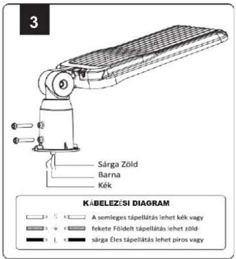
natural_image
Technical line drawing of two streetlight sensors labeled VA, showing mechanical components without any text or symbols.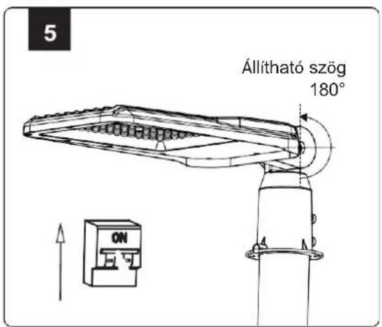
Non-replaceable light source
Non-replaceable control gear
1
2
natural_image
Technical line drawing of a mechanical device with a rectangular housing and cylindrical component (no text or symbols)3
SCHEMA ELETTRICO
natural_image
Technical line drawings of two mechanical components: a articulated arm and a multi-axle device (no text or symbols present)5
NOTA
WPROWADZENIE I GWARANCJA
Non-replaceable light source
Non-replaceable control gear
1
2
natural_image
Technical line drawing of a mechanical device with a rectangular housing and cylindrical component (no text or symbols)3
natural_image
Technical line drawing of two robotic arm components labeled 'LU', showing structural details without any text or symbols on the devices themselves.5

UWAGA
MANUAL DE INSTRUÇÕES
CANDEEIRO DE RUA LED COM ÂNGULO AJUSTÁVEL
DADOS TÉCNICOS
| MODELO | VT-55ST | VT-105ST |
| SKU | 23618, 23619 | 23620, 23621 |
| ÁGUAS | 50W | 100W |
| LUMENS@CÓDIGO GERAL | 4700 LM | 9400 LM |
| ÂNGULO DO FEIXE | 100° | 100° |
| DF | >0.9 | >0.9 |
| IRC | ≥80 | ≥80 |
| TEMPERATURA DE FUNCIONAMENTO | -20°C a +40°C | -20°C a +40°C |
| DURAÇÃO DA VIDA | 30.000 horas | 30.000 horas |
| CICLO ON/OFF | 20.000 vezes | 20.000 vezes |
| PESO LÍQUIDO (g) | 670 | 1035 |
| TENSÃO DE ENTRADA | AC: 220-240V, 50/60Hz | |
| DIÂMETRO DE MONTAGEM | 60 mm | 60 mm |
| ALTURA DE MONTAGEM | 3-5m | 5-8 m |
| MAX. ÁREA PROJECTADA | 20-30m2 | 30-40m2 |
| TIPO DE CORPO | Alumínio+PC | Alumínio+PC |
| DIMENSÃO | 412x139x92mm | 488x183x92mm |

05 YEAR WARRANTY®
IP65 RATING
Non-replaceable light source
Non-replaceable control gear
1
2
natural_image
Technical line drawing of a mechanical device with a rectangular housing and cylindrical component (no text or symbols)3
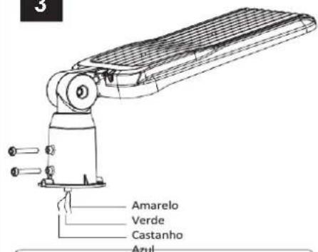
DIAGRAMA DE CABLAGEM
natural_image
Technical line drawings of two mechanical or electronic components with no visible text or symbols5
MANUAL DE INSTRUCTIUNI
A CONDUS LUMINA STRADALĂ CU UNGHI REGLABIL
DATE TEHNICE
| MODEL | VT-55ST | VT-105ST |
| SKU | 23618, 23619 | 23620, 23621 |
| WATTS | 50W | 100W |
| LUMENI@CODGENERAL | 4700 LM | 9400 LM |
| UNGHIULFASCICULULUI | 100° | 100° |
| DF | >0.9 | >0.9 |
| CRI | ≥80 | ≥80 |
| TEMPERATURA DEFUNCTIONARE | -20°C până la +40°C | -20°C până la +40°C |
| DURATA DE VIATĂ | 30.000 de ore | 30.000 de ore |
| CICLULPORNIT/OPRIT | De 20.000 de ori | De 20.000 de ori |
| GREUTATEA NETĂ (g) | 670 | 1035 |
| TENSIUNE DE INTRARE | AC: 220-240V, 50/60Hz | |
| DIAMETRU DEMONTARE | 60 mm | 60 mm |
| ÎNĂLTIMEA DEMONTARE | 3-5m | 5-8 m |
| MAX. ZONAPROIECTATĂ | 20-30m2 | 30-40m2 |
| TIPUL CORPULUI | Aluminiu+PC | Aluminiu+PC |
| DIMENSIUNE | 412x139x92mm | 488x183x92mm |
Non-replaceable light source
Non-replaceable control gear
1

2
natural_image
Technical line drawing of a mechanical device with a rectangular housing and cylindrical component (no text or symbols)3
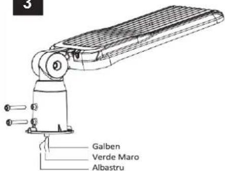
DIAGRAMA DE CABLARE
4
natural_image
Technical line drawings of two robotic devices with labeled 'OR' (no text or symbols on the devices themselves)5
NOTĂ
Non-replaceable light source
Non-replaceable control gear
1
2
natural_image
Technical line drawing of a mechanical device with a cylindrical component and ribbed housing (no text or symbols)3
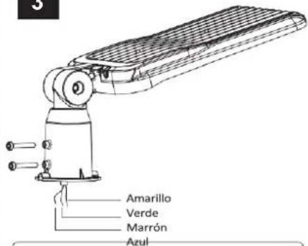
DIAGRAMA DE CABLEADO
natural_image
Technical line drawings of two mechanical components: a vertical support with a mesh panel and a multi-layered device with a grid-patterned cover (no text or symbols)5
NOTA
Brand : V-TAC
Model : VT55ST
Category : Lighting