CT7.3 LCRS - Speaker BOWERS & WILKINS - Free user manual and instructions
Find the device manual for free CT7.3 LCRS BOWERS & WILKINS in PDF.
User questions about CT7.3 LCRS BOWERS & WILKINS
0 question about this device. Answer the ones you know or ask your own.
Ask a new question about this device
Download the instructions for your Speaker in PDF format for free! Find your manual CT7.3 LCRS - BOWERS & WILKINS and take your electronic device back in hand. On this page are published all the documents necessary for the use of your device. CT7.3 LCRS by BOWERS & WILKINS.
USER MANUAL CT7.3 LCRS BOWERS & WILKINS
Installation Instructions
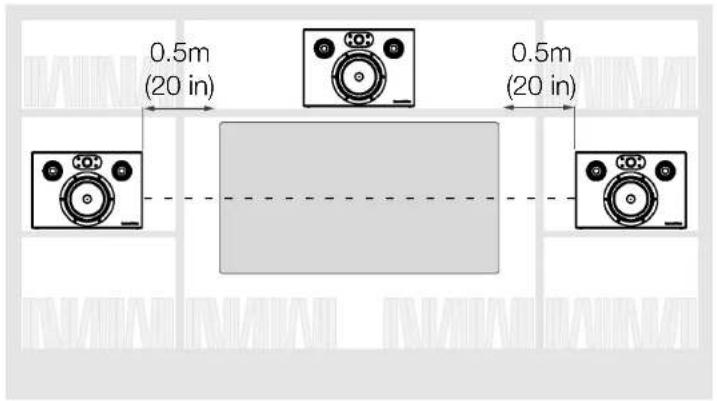
Figure 1
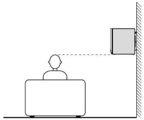
Figure 2
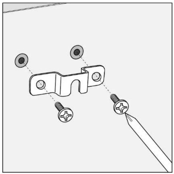
Figure 3
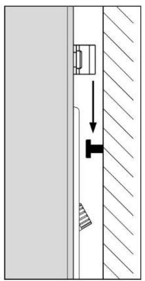
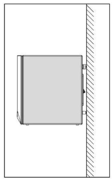
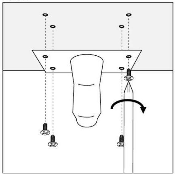
Figure 4
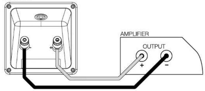
Figure 5a

&IGURE B
&IGURE

dB
Hz
dB
Hz
dB
Hz
Contents
English
Installation manual .........2
Limited Warranty. 3
Français
Specifications.....42-44
English
Installation manual
Dear customer,
Thank you for choosing Bowers & Wilkins. Please read this manual fully before unpacking and installing the product. It will help you to optimise its performance. B&W maintains a network of dedicated distributors in over 60 countries who will be able to help you should you have any problems your dealer cannot resolve.
Environmental Information


All B&W products are designed to comply with international directives on the Restriction of Hazardous Substances
(RoHS) in electrical and electronic equipment and the disposal of Waste Electrical and Electronic Equipment (WEEE). These symbols indicate compliance and that the products must be appropriately recycled or processed in accordance with these directives. Consult your local waste disposal authority for guidance.
Carton Contents
Check in the carton for:
4 Adhesive rubber feet
2 Adhesive rubber spacers
2 Port plugs
1 Speakon® plug
2 Wall brackets
4 M6 bolts
Speaker Installation
CT700 Series speakers can either be installed within existing or custom designed home theatre system cabinets, or wall mounted using a variety of brackets.
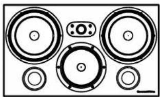
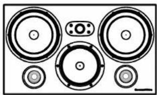
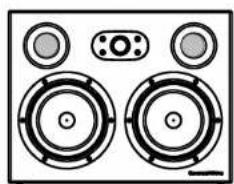
If the speakers are to be installed within a cabinet it is important to ensure that it is capable of carrying their weight and that it is structurally sound. Significant vibration of the cabinet panels may seriously affect the subjective performance of the speakers. Figure 1 illustrates the installation of three CT700 Series speakers in a home theatre cabinet showing the recommended dimensions between the speakers and space around them.
Adhesive rubber feet are supplied for attachment to the underside of the speakers in order both to protect the cabinet finish and to reduce vibration. Attach one adhesive foot at each underside corner of the speakers.
If gaps wider than approximately 20mm (3/4 inch) remain around a speaker when it has been installed in a cabinet, the acoustic performance will be improved if the gaps are filled. Use carefully cut pieces of upholstery or acoustic foam to fill the gaps as far back as is practical and flush with the front panel of the speaker. Only use foam with an appropriate fire safety rating.
CT700 Series speakers can also be wall mounted using one of two methods.
Wall Brackets:
The speakers incorporate 4 M6 tapped inserts in their back panels for attachment of the two brackets supplied. Always use both brackets. Use the supplied M6 bolts to attach the brackets to the back of the speaker. The two supplied adhesive rubber spacers can be used to cushion the speaker against the wall.
Figure 3 illustrates use of the brackets. Before using the brackets ensure that the wall and fixings are capable of supporting the weight of the speaker. B&W can accept no liability for any failure of wall and/or fixings.
Ball-joint Brackets:
The speakers incorporate 4 M6 tapped inserts in their undersides that enable the speakers to be wall-mounted using adjustable ball-joint style mounting brackets designed for 127mm× 69.9mm (5 in × 2.75 in) mounting hole centres. Your dealer or local B&W distributor will be able to advise you on the selection of appropriate brackets.
To attach a ball-joint style bracket to a CT700 Series speaker first securely attach the socket plate to the underside of the speaker. Figure 4 illustrates this procedure.
Once the socket plate is attached to the speaker, the assembly may be connected to the ball component attached to the wall. Ensure that the manufacturer's instructions for attaching the bracket to the wall are followed correctly and that the wall and fixings are capable of supporting the weight of the speaker. B&W can accept no liability for any failure of wall and/or fixings.
Regardless of the style of installation take care when lifting the speakers into position. They are unwieldy and heavy and best handled by two people working together.
The black fabric grilles are attached by magnets and may be removed if desired. Take care not to touch the drive units when removing or replacing the grilles.
Speaker Positioning
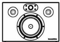
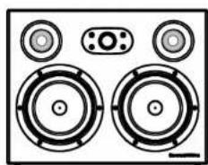
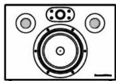
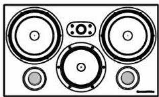
CT700 Series speakers used for the front left and right channels in a home theatre system should be positioned one either side of the screen on the horizontal centre-line. They should be within approximately 0.5m (20 in) of the sides of the screen to help keep the sound image in scale with the visual image. See Figures 1 and 2.
A CT700 Series speaker used for the centre channel in a home theatre system should be positioned centrally either directly above or below the screen. In the case of acoustically transparent screens, the centre channel speaker should be positioned centrally behind the screen.
CT700 Series speakers used for the surround channels in a home theatre system should be positioned above and to either side or behind the listening position.
Stray Magnetic Fields
The speaker drive units create stray magnetic fields that extend beyond the boundaries of the cabinet. We recommend you keep magnetically sensitive articles (CRT television and computer screens, computer discs, audio and video tapes, swipe cards and the like) at least 0.5m (20 in) from the speaker. LCD and plasma screens are not affected by magnetic fields.
Connections
All connections should be made with the equipment switched off.
CT700 Series speakers have a pair binding post connection terminals and one Neutrik® Speakon® connection socket on their rear panels. The binding post terminals provide quick and easy connection of stripped wires while the Speakon socket provides a more secure and reliable connection method.
If the binding post terminals are to be used, connect the positive cable to the red terminal and the negative cable to the black terminal. Incorrect connection can result in poor imaging and loss of bass. Figure 5a illustrates use of the binding post terminals
If the Speakon option is to be used, disassemble the Speakon plug as shown in Figure 5b, connect the positive cable to the terminal marked +1 and the negative cable to the terminal marked -1. Incorrect connection can result in poor imaging and loss of bass. Once the plug is reassembled it can be inserted into the socket and locked by twisting clockwise.
Ask your dealer for advice when selecting speaker cable. Keep its total impedance below the maximum recommended in the speaker specification and use a low inductance cable to avoid attenuation of high frequencies.
Neutrik and the names of Neutrik products referenced herein are either trademarks and/or service marks of Neutrik.
Fine Tuning
Before fine tuning, make sure that all the connections in the installation are correct and secure.
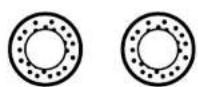
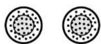
If the bass seems uneven with frequency this will most probably be due to resonance modes in the listening room. Even small changes in the listening position can have a profound effect on how these resonances affect the sound. Try moving the listening position. The presence and position of large pieces of furniture can also influence resonance modes. If you want generally to reduce the volume of bass fit the foam plugs in the speakers' port tubes as illustrated in Figure 6.
If the sound is too bright, increasing the amount of soft furnishing in the room (heavier curtains for example) may help balance the sound. Conversely, reducing the amount of soft furnishing may help brighten a dull sound.
Some rooms suffer from "flutter echoes" - echoes that "bounce" between parallel room boundaries. Flutter echoes can colour the sound of the speakers in the room. Test for flutter echoes by standing in the middle of the room and clapping your hands. Flutter echoes
can be reduced by placing irregular shaped items or non-reflective surfaces, bookshelves, rugs or pictures for example, on one of the offending walls or floor.
Running-in Period
The performance of the speaker will change subtly during the initial listening period. If the speaker has been stored in a cold environment, the damping compounds and suspension materials of the drive units will take some time to recover their correct mechanical properties. The drive unit suspensions will also loosen up during the first hours of use. The time taken for the speaker to achieve its intended performance will vary depending on previous storage conditions and how it is used. As a guide, allow up to a week for the temperature effects to stabilise and 15 hours of average use for the mechanical parts to attain their intended design characteristics.
However, longer run-in periods (as long as a month) have been reported and there is evidence to suggest that this has little to do with the speaker changing and more to do with the listener getting used to the new sound. This is especially so with highly revealing speakers such as these where there may be a significant increase in the amount of detail compared with what the listener has previously been used to; the sound may at first appear too "up front" and perhaps a little hard. After an extended period of time the sound will seem to mellow, but without losing clarity and detail.
Aftercare
The cabinet surfaces usually only require dusting. If you wish to use an aerosol or other cleaner, remove the grille first by gently pulling it away from the cabinet. Spray aerosols onto the cleaning cloth, not directly onto the product. Test a small area first, as some cleaning products may damage some of the surfaces. Avoid products that are abrasive, or contain acid, alkali or anti-bacterial agents. Do not use cleaning agents on the drive units. The grille fabric may be cleaned with a normal clothes brush whilst the grille is detached from the cabinet. Avoid touching the drive units, especially the tweeter, as damage may result.
Limited Warranty
This product has been designed and manufactured to the highest quality standards. However, if something does go wrong with this product, B&W Group Ltd. and its national distributors warrant free of charge labour (exclusion may apply) and replacement parts in any country served by an official B&W distributor.
This limited warranty is valid for a period of five years from the date of purchase or two years for electronics including amplified loudspeakers.
Terms and Conditions
1 The warranty is limited to the repair of the equipment. Neither transportation, nor any other costs, nor any risk for removal, transportation and installation of products is covered by this warranty.
2 This warranty is only valid for the original owner. It is not transferable.
3 This warranty will not be applicable in cases other than defects in materials and/or workmanship at the time of purchase and will not be applicable:
a. for damages caused by incorrect installation, connection or packing,
b. for damages caused by any use other than correct use described in the user manual, negligence, modifications, or use of parts that are not made or authorised by B&W,
c. for damages caused by faulty or unsuitable ancillary equipment,
d. for damages caused by accidents, lightning, water, fire heat, war, public disturbances or any other cause beyond the reasonable control of B&W and its appointed distributors,
e. for products whose serial number has been altered, deleted, removed or made illegible,
f. if repairs or modifications have been executed by an unauthorised person.
4 This guarantee complements any national/regional law obligations of dealers or national distributors and does not affect your statutory rights as a customer.
How to claim repairs under warranty
Should service be required, please follow the following procedure:
1 If the equipment is being used in the country of purchase, you should contact the B&W authorised dealer from whom the equipment was purchased.
2 If the equipment is being used outside the country of purchase, you should contact the B&W national distributor in the country of residence who will advise where the equipment can be serviced. You can call B&W in the UK or visit our web site to get the contact details of your local distributor.
To validate your warranty, you will need to produce the warranty booklet completed and stamped by your dealer on the date of purchase. Alternatively, you will need the original sales invoice or other proof of ownership and date of purchase.
IocapaItecB He KacaTbCn DnΦΦy3OpOB dHAMIKOB npn HaDeBaHnn nN CHrTHn 3aunTHoJ peWetKn.
Bb6op meCTa JIA KOJIOHOK
Пи ИСПОЛБЗOBAHИ NOKОHOK cepIN CT700 B KaueCTBe pOHTaNbHbIX B CnCTeMe DomaUHero TeaTpa, IN HUxHNO yCTaHOBNTb NO O6eIM CTOpOHAM 3KpaHa, Ha yPoBHe erO ueHtpa. OHN DoJXHbIb 6bITb np6In3nteHbHo Ha 0.5 M (20 in) ot CTopoH 3KpaHa, UTO6bl 3ByKOBoI O6pa3 COBnaI no MacuTa6y C Bu3yaJIbHbIM.CM.Pnc.1 n2.
Ecnn AC CT700 nrrpaet pOB ueHTpaIbHOJ KOIOHKn, OHa DOJXHa 6bITb paCNOLOKeHa CBepy nn Jx ChN3y 3KpaHa, B 3aBNCIMoCTn OT TORO, rDe OHa 6bnke K ypOBHyowei CnywateJI. B cnyuae akycTnueckn npO3paUHoro 3KpaHa, ee CneDyET NODBecNTb 3a CEHTpOM 3KpaHa.
Pn nncnoB3ObaHnn AC CT700 B kaueCTBe TbIOBbIX B CNTeMe DomaHrero TeaTpa Nx CneNyET paCNOLOXKntb 3a MeCTOM CnywaTeJN BBiWe Hero, NO OBeHM CTOpOHAM OT KpeCJa nnDnBaHa.
PaccenHHoe MarHHTHOJ NOJe
HnHaMnKoKOHOK CO3aHOT MaHHTHOe NOle, BbIXOJaUee 3a INx npedeIb. Mbl peKomeHdyem DePxAb MaHHTOuyBCTBNTbHbIe PpeDMeTb (KNHeCKoNtBIE TeJIeBUN3Opbl, DcCJIeN, NcCKeTbl, MaHHTbIe ayINo IN BuJeOKacCeTbl, KApTOUYK IN T.I.) Ha pacCTOARHH MNHMym 0.5 M OT KOHOK. XnIKoKpncTaIIuYeCKne (LCD) n nnA3MeHHbIe 3KpaHbI He noDbepXeHbl BO3dEInCTBNU MoHHTbIX IOnen.
PoiocoeHHeHne
Bce nodknIOueHn IeNaIOTc TOnbKO npN BbIKIOueHHOM O6OpyDoBaHn.
Y KOJHOK CT700 IMEOTCA DBe napbl O6bIHyBX KJIeMM, a TaKxpe Odn pa3bem Neutrik Speakon Ha 3aJHne NaHeN. 3axmHbIe KJIeMMbI o6ecnueHBaOT 6bICTpoe n HAdexHXoe CoeINHeHne 3aUuEHHbIX KOHcOB Ka6eNa, a rHe3da Speakon-6oJee HAdexHXoe n 6be3Oanchoe CoeINHeHne.
Дя coeHHeN KOnOHOK c NOMObIO 3aXHMbIX KJIeMM, NOcOeHInTe PIIOCOB KoHeU Ka6eJRA K KpacHoi KJIeMMe, a MInycoBOI K UePHoH. HeBepHOe NOKIOUChE NpINBeTe K NCKaKeHNIO 3ByKOBOO O6pa3a n ytepe 6acob. Ha Pnc. 5a noKa3aHo NOcOeHHeHc E NOMObIO KOHOOHbIX KJIeMM.
Длг coeДинEHн KOLHOK c nomOuBIO Speakon, chaHa pa36epnte pa3bem Speakon, kaK noka3aHo Ha Pnc. 5b n noCoeDInHnTe pIocOBoi KoHeu Ka6eJIH K KOHTaKtY, o6o3NaueHHOMy +1, a MNHycOBoi - K KOHTaKtY, o6o3NaueHHOMy -1. HeBepHoe coeDinHne npNBeDet K nCKaKeHIO 3ByKOBOrO O6pa3a n Notepe 6acOB. IocNe TORO, ka Pa3bE m 6yDet BHObB cO6paH, erO moXHo 6yDeT BCTaBnTB B rHe3do N 3aФИКсИрОВaTb, NOBepHyB n QacOBoi CTpeJIke.
Nonpocnte BaWero DnJIepa NopeKoMeHDoBaTb Ka6eIb. CtapaiTeCb, TTo6bl erO mNpeHaC 6bl HIXe MaKcImaJIbHO dOnyCTmORo B cNeUΦnKauIN, a INdYkTbHBOCtB ToXe 6bla Hn3KoJ, TTo6bl He OCNa6ntb BBICOKne YactOTbl.
Neutrik and HaanmeHOBAHn npOdyKToB Neutrik, yNOMHaEMbIe B TeKCTe, 3TO JNoTO TopROBbIe MapKn, JNoTO TopROBbIe/CepBuChbIe MapKn Neutrik.
ToHkaHaCTpOka
IpepeokohuataeIbHOnToCHoNHaCTpOiKoI y6eIntecb, YTO BCE NOkIIOUeHO npaBnIbHO n HaJeXHo.
Ecni 6ac kaXeTcH hepABHomepbIM no qactote, 3TO CKopee BCero Bbl3BaHO pe3OHaHCAMn (CTORHM BOHNAMn) B KOMhATE npocnyuBAHn. Ppi 3tOM daxe He6oIbIwne N3MeHeHn B NOIOKeHHN CNYaTeJI MOryT npIBoDINTb K 3HaHTeJIbHOMy BINHAHIO pe3OHaHCOB Ha 3ByaHne. NpOboYnte NOMeHTb MeTo DnI npocNyuBAHn. HAnuYe n pa3MeUeHne KpyHOrabapuTHoM Me6eIM MoXe TAKXe BInrTaH na pe3OHaHcbl. EcNI Bbl XOTnte BOO6ue CHn3NTb yPOBeHb 6aOB, TO BCTaBbTe NOPONHOByIO 3arLykUy B NoPT faoOHBepTopa, KaK noka3aHo Ha Pnc.6.
Ecnn 3Byk CnIuKOM pe3Kn((RpKn)),O6abBte MArKoM Me6eBn B KOMHaTe (HanpImep, NOBeCbTe TAnKeJIbIe uTOpbl), HnN HAO6OpOT - y6epnte nx, ecnn 3Byk rnyxoi n 6e3Xn3HeHHbI.
Akyctnka HeKOTopbIX KOMHAT CtpaJaet OT 3ΦΦeKTA 3XO, Bbl3BaHHoro MHOROHCNEHHbIMN OTPaxKeHNMI 3Byka OT napaJIeNBbIX CTen. TaKoe 3Xo cNooc6HO NCKa3NTb (OKpacNTb) 3ByuHne KOLOHOK B NOMeUHm. POBepbTe NOMEUeHne Ha 3Xo, BCTab NOCpeDN KOMHaTbI, ydApNB B NaDoWN I npCnyuINBaRcB K 6bICTpbIM OT3BykAM. INx MOxHO UMeHbUNTB 3a Cuet NCIOB3OBaHnE HeperyJrPHbIX NOBepxHOCTeN, TAKNX KA KKNKHbIE NOLKN NIN KpyNHOra6apHTHa Me6eNb BDOJIb NOD03pTeJIbHbIX Ha OTPaXKeHne CTen.
PporpBn npnpa6oTka
3ByaHHe AC cnerKa MeHHeTcB TeueHne
HaahalbHoro nepnoDa npocnyuBaHHa. Ecnn
KoJOnHKa XpaHnIacB XOLOdHom NOMEeHN, TO
DJIa Demnpuyuix MaTeepnaNoB I NOdBeca
DNHAMKOB NOTpe6yETcR HeKOTOpoe BpEM Ha
BOcCTaHOBLeHHe MExAHueCKnx CBoiCTB. NoDbec
DnΦpy3opa TAKKe CnERka ChnXaet CBOIO
XeCTKoCTb B TeueHHe NepBbIX YacOB pa60tbl.
BpEM, KOTOpOE Notpe6yETcA DCnIPOHoro
BbIXOda Ha paChEThBiE XapAKTePncTNI 3aBNCNT OT
ycNobNxaPHeHn INHTehCNBHOCTN
INcONb3OBaHHa. KaK npabNIO, Notpe6yETcR HeJeNa
Ha ycTaPaeHHra TemnepaTyPhbIX 3ΦΦeKTOB IN OKOIO
15 YacOB Ha DOCTNXeHHe MEXAHueCKMn YactrMM
XeJaembIX XapaKTePncTIK.
KHam HnHOrda NoCTyNaIOT OT3bIBbl, YTO Heo6xOdM 60Jee dInTeIbHbI nepNoI npipa6oTK (HaNPmep, MeCra), Ondako 3TO, KaN npabINO, He IMeET OTHoWeHnK N3MeHeHnM B CBOiCTBax AC, a CKopee BCero CBa3aHO C npNBbIKaHnEM CnywateTn K
HOBOMY DnHr Hero 3ByuHaHIO.3To, npexDe BCero OTHOCITcK KOJONHKaM C BbICOKo pa3pewaIOUe CNOC6HOCTbIO, rDe CnyuTaJIIO MOKeT OTKpbITbcra 3HaHTeNbHO 60IbUeE KOINueCTBO DeTaJIeN, YEM TO, K KOTOpOMy OH paHee npNBbIK; 3ByuHaHne NOHaayMoKeT NOKa3aTbCnYepeCuyp «BbIpyeHHbIM» HEMHO TpydHbIM dJIr BOCPnAITn. Ondako IocNe 6OJe e nn MeHee npOJONKtEnbHO BrPeMeHN Bam NOKaKeTcR, YTO 3BYK CTaJI MmYrnpAHTHee, Ho 6e3 KaKoHn6yDb yTePN ACHOCTn IN DetalbHOCTn.
YXOD 3A KOJIOHKAMN
O6bIyHO KOpnyCa KOJIOHOK He Tpe6yOT HnUero, KpOME OChCTKn OT nbIIN. EcN JxE Bbl 3axOTnTe NcNoJIb3OBaTb a3pO3OJIb dJIy NcCTKn, To ChauJa yDaJIte 3aunTHyO peWetKy, OCTOPOXHO NOTAHYB ee 3a pamky. PacblnIe Ta3pO3OJIb Ha npOTnpOCHyTO TkaHb, a He Ha KOpNc. IpOBepbTe DeIcTBne a3pO3OJIa CHaJala Ha He6oJIbWOM yAcTKe NOBepXHOCTn, T.K. HEKOTOpbIe BeIeCTBa MOrTy Bbl3BaTb N3MeHeHne OKpackn. I36eraIte a6pa3NBbIX, KNCIoTHbIX, UeJIOnyHbIX nII naNTbAKTepnaJIbHbIX BeIeCTB. I36eraIte IONaDaHnma MOUxN X BeIeCTB Ha TkaHb 3aUnTHoH peWETKn, T.K. Ha HeN MOrTy OCTaTbcra nTHa. TkaHb peWETOK MoXHO YCHTNb ObUYHO OdExHoi UeTKoI nII x He HacaIKoI dJI NaIInecoca. I36eraIte KacAHn DaICPfOy3OpOB DInHaMnKOB, OCO6EHNO TBNTePOB, T.K. 3TO MOXET PpNBecTn K INX IOBpeKDeHIIO.
OrpaHnueHHa rapaHTna
JaHHe n3dJIe 6bIIO pa3pa6oTaHO npOn3BeDeHO B COOTBETCTBHN C BBICOaHIMM CTaHdApTAMN KaueCTBa. OJHaKo, pI INOBHApXeHn KAKo-Ni6o HeNCnpabHocHT, KomnaHnB&W Group Ltd. n eHaUNHOHbHbIe DnCTpNbTObI rapaHTpyOT 6ecPNaTHbI peMOHT (CyueCTByOT HeKOToPbIE NCKNUOeHn) n 3aMeHy qAcTeB I JIOBoN cTpaHe, ObcnyxNBaEMoOfUuHaJIbHbIM dNCTpNbBOtOpOM KomnaHn B&W.
JaHHa ORpaHnueHHa rapaHTn DaeCTBnteJIbHa Ha nepIOoNHO roda co nH npNo6peTeHn 3JeHn KaHeHbIM Ntpe6nteJem.
YcIOBra rapaHTn
1Данная rapaHTnO orpaHnUbaeTcNouHkoIobopyoBaHHa.3aTpataNo nepeBO3Ke nIO6bIeDpyrHe 3aTaPtaI, a TaKke pNCK npN OTKJIooHEn,nepeBO3Ke nHCTaJInpOBaHHu N3DeHn HeNOKpbIBaOTc DaHHoR rapaHTnei.
2 DieCTBne daHHoI rapaHTn pacnpoctpaHReTcra ToJIbKO Ha nepBOHaayJbHO BlaJeJbUca. IpaANTn He MoKet 6bITb nepeDaHa dpyromy niu.
3Даннаг rapaHTnpaCnpocTpaHReTcToIbKOHa Te HEnCnpaBHOCTN,KOTOpbie Bbl3BaHbI DeΦeKTHbIMMaTePnaJAmN/INN DeΦeKTAmN
PnnpOn3BOOCTBe Ha MOMENT npNo6peTeHnI He pacnpocTpaHReTc:
a. NaOBpeJXeHn, Bbl3BaHHbIe HnpeBnIbHOuHCTaJIJIaCnei, NOcOeINHeHEm nnynynaKOBKO,
6. Na NOBpeJXeHn, BbI3BaHHbIe IcNoJIb3OBaHHeM, He COOTBeTCTByIOUzIM OINCAHHOMy B pyKoBOdCTBe No npImeHHeHIO, a TaKxE HeIpaBnJIbHbIM ObpaueHHeM, MoINΦuPpOBaHHeM INI INCNoJIb3OBaHHeM 3aNaChbIX qacteI, He pOnI3BeDeHHbIX INI He ODo6peHbIX KOMpaHHeN B&W,
B. Na NOBpeKJeHnA, BbI3BaHHbIe HeNCpBaHbIM IIN HEnoDxOJaUM BCNOMOraTeJIbHbIM O6OpyDoBaHnEm,
T. Na NOBpeKDeHn, BbI3BaHHbIe HeCchAcTHbIMN CnyaAMN, MOHnei, BOoI, NOXapOM, BOHOn, Np6NIuHbIMN 6ecnpAkmn IIN JxE IIO6bIMN dpyrIMn pakTopamn, He noPnaIauUImn POnkToPb KOMNaHN B&W n eOphuNaJIbHbIX DInCTpn6bIOTOpOB,
I. Ha n3delen, cepinHbH Homep KOtOpbIX 6bln N3MeHen, yHNUTOXeH INN CDeNaH Hey3HaBaEMbIM,
e. Ha n3dJIIN, NOUHKA INI MOnDnФKauN KOTOpbIX npON3BOJINcB JInCOM, He yNoJHOMOueHHbIM KOMNaHne B&W.
4Данная rapaHTnЯ rBJIeTcI dONJIHeHnEM K HaUHOHaJIbHbIM/perNoHAJIbHbIM 3aKoHOdaTeNbCTBaM,KOTOpbIM NOdYnHrOTcR dInepbl NNHaUHOHaJIbHbIe IINCTpNbIOTOpbl,TO eCTb pN BO3HnKHOBeHm nPoTNBOpeuH, HaUHOHaJIbHbIe/perNoHaJIbHbIe 3aKoHOdaTeNbCTBa IMeIOT npnOpNTeTHyIO Cnly. DaHHa rapaHTnI He hapywaet Baunx npab notpe6nteJ.
Kya o6paTntb8a rapaHTnHbIM 0ocnykBaHneM
Pn Heo6xOaHmocTn noJyHeHna rapaHTnHoro 06cnyXuBaHHa, BbIOJNHte CneDyUOune WaH:
1 EcnnobopydoBaHne nCnOJb3yeTcB CtpaHepno6peTeHHaBHeo6XdmoCBHa3atbcN CyNoJIHOMOeHHbIM dIInepom KOMNaHmB&W,y KOtOporo 6bln npno6peTeHo o60pDoBaHne.
2 EcJnOBOpyIOBaHne nCnoJIb3YeTcra 3a npedeIamn CtpaHbI npno6peTeHHa, Bam Heo6xOIMMO CB83aTbcra C HaUHOHaJIbHbIM dNCTpN6bHOTOpOM KOMNaHH B&W B daHHo CTpaHe, KOtOpBn NOCOBETyET Bam, rDe MOXHO NOuHHb OBOpYIOBaHne. Bbl MoKTe N03BOHTb B KOMNaHH B&W B BeNIKOBpTuHHu NIN Xe NocETnTB Hau We6caNT, YTObI y3HaTb KOHTaKTHbI aDpec BaWero MeCTHOrO dNCTpN6bHOTopa.
IpyroeCBnTeBCTBO BnaDeHcC DaToN NOKyNk.
Česky
Návod k použiti
Vázenzý zákazníku,
dekujeme vam, ze jste si zvolili reprsoustavy firmy Bowers & Wilkins. Pred jejich vybalenim a instalaci si prosim napred prectete celyarto manual.
EU DECLARATION OF CONFORMITY
We,
B&W Group Ltd.
whose registered office is situated at
Dale Road, Worthing, West Sussex, BN11 2BH, United Kingdom
declare under our sole responsibility that the products:
CT7.3 LCRS
CT7.4LCRS
CT7.5LCRS
complies with the EU Electro-Magnetic Compatibility (EMC) Directive 89/336/EEC, in pursuance of which the following standards have been applied:
EN 61000-6-1:2001
EN61000-6-3:2001
EN 55020:2002
EN 55013:2001
and complies with the EU General Product Safety 2001/95/EC, in pursuance of which the following standard has been applied:
EN 60065:2002
This declaration attests that the manufacturing process quality control and product documentation accord with the need to assure continued compliance.
The attention of the user is drawn to any special measures regarding the use of this equipment that may be detailed in the owner's manual.
Signed:

G Edwards
Executive Vice President, Operations
B&W Group Ltd.
CT7.3
CT7.4
CT7.5
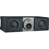
CT7.3 LCRS
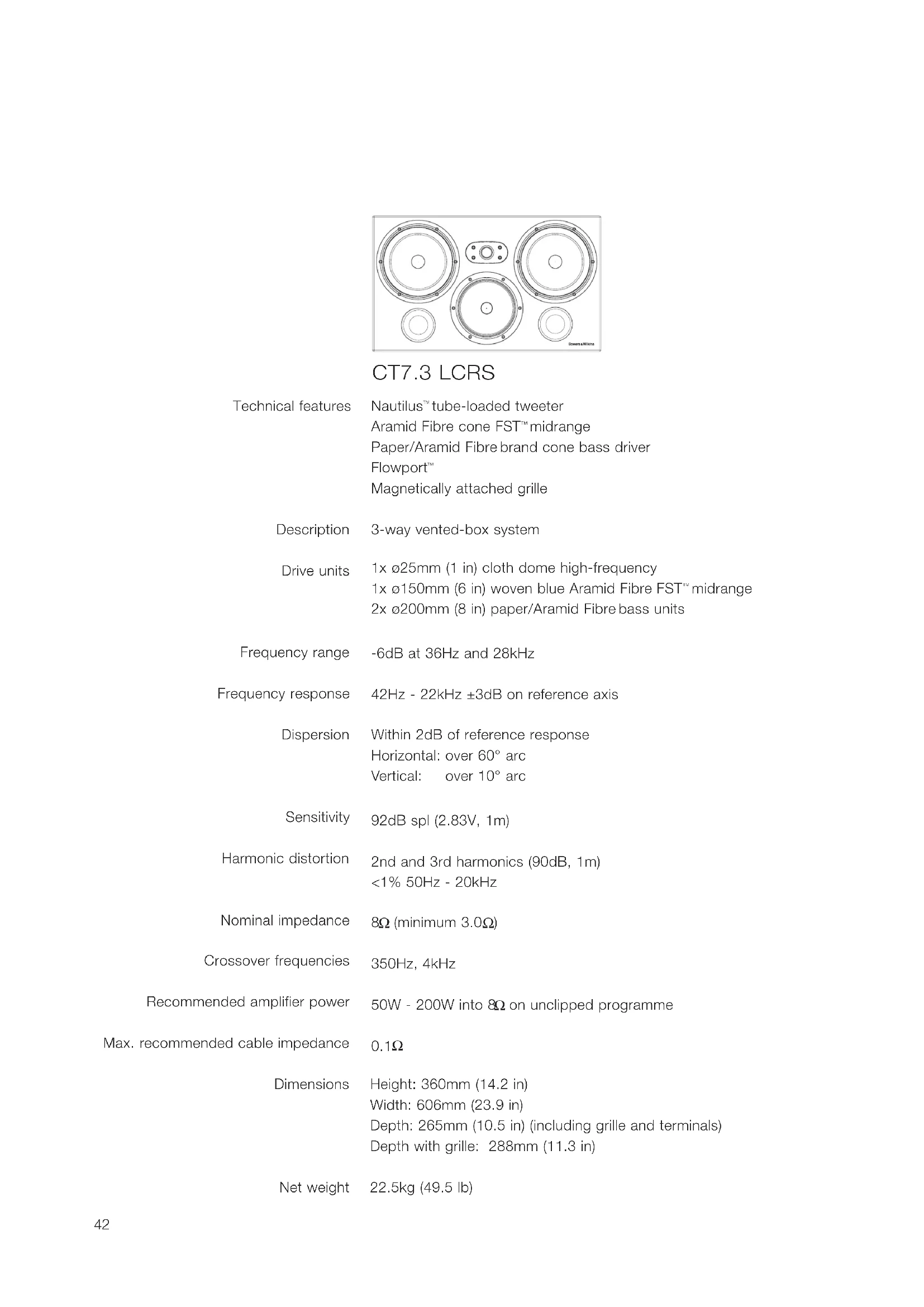
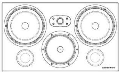
| Technical features | Nautilus™ tube-loaded tweeter Aramid Fibre cone FST™ midrange Paper/Aramid Fibre brand cone bass driver Flowport™ Magnetically attached grille |
| Description | 3-way vented-box system |
| Drive units | 1x ø25mm (1 in) cloth dome high-frequency 1x ø150mm (6 in) woven blue Aramid Fibre FST™ midrange 2x ø200mm (8 in) paper/Aramid Fibre bass units |
| Frequency range | -6dB at 36Hz and 28kHz |
| Frequency response | 42Hz - 22kHz ±3dB on reference axis |
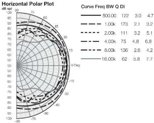
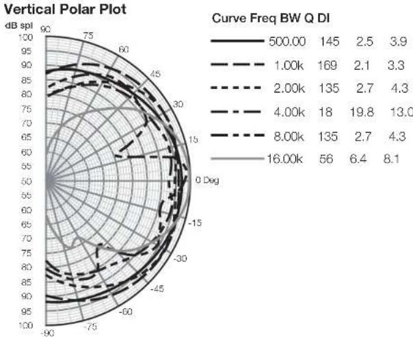
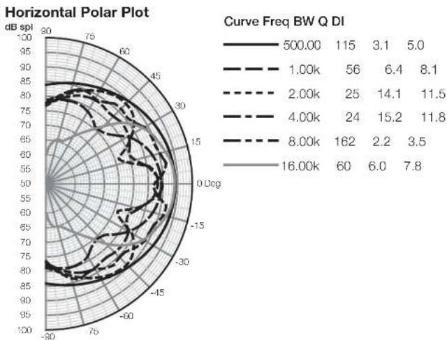
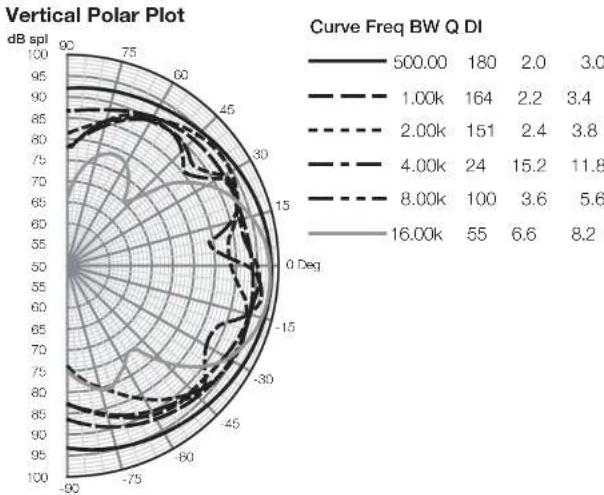
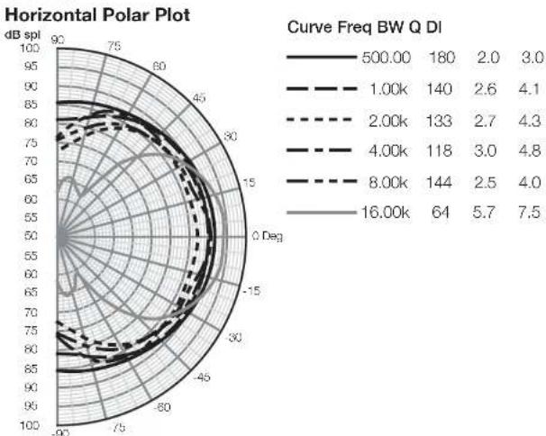
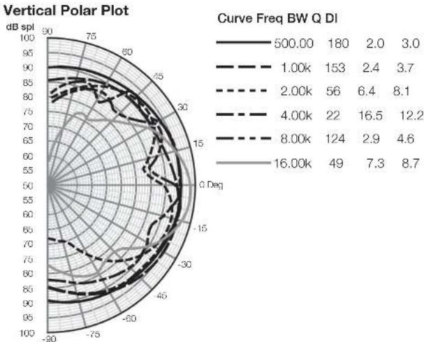
| Dispersion | Within 2dB of reference response Horizontal: over 60° arc Vertical: over 10° arc |
| Sensitivity | 92dB spl (2.83V, 1m) |
| Harmonic distortion | 2nd and 3rd harmonics (90dB, 1m) <1% 50Hz - 20kHz |
| Nominal impedance | 8Ω (minimum 3.0Ω) |
| Passover frequencies | 350Hz, 4kHz |
| Red amplifier power | 50W - 200W into 8Ω on unclipped programme |
| Red cable impedance | 0.1Ω |
| Dimensions | Height: 360mm (14.2 in) Width: 606mm (23.9 in) Depth: 265mm (10.5 in) (including grille and terminals) Depth with grille: 288mm (11.3 in) |
| Net weight | 22.5kg (49.5 lb) |
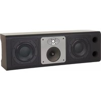
CT7.4 LCRS
Technical features Nautilus tube-loaded tweeter
Aramid Fibre cone bass/midrange
Flowport
Magnetically attached grille
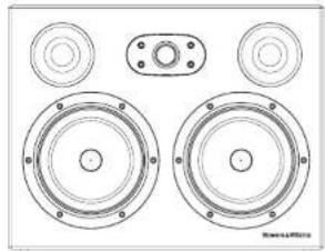
Description 2-way vented-box system
Drive units 1x 025mm (1 in) cloth dome high-frequency
2x 0165mm (6.5 in) woven Aramid Fibre cone bass/midrange
Frequency range -6dB at 43Hz and 28kHz
Frequency response 49Hz - 22kHz ±3dB on reference axis
Dispersion Within 2dB of reference response
Horizontal: over 60^ arc
Vertical: over 10^ arc
Sensitivity 94dB spl (2.83V, 1m)
Harmonic distortion 2nd and 3rd harmonics (90dB, 1m)
<1% 90Hz - 20kHz
Nominal impedance 8Ω (minimum 4.0Ω)
Crossover frequency 4kHz
Recommended amplifier power 50W - 150W into 8Ω on unclipped programme
Max. recommended cable impedance 0.1Ω
Dimensions Height: 343mm (13.5 in)
Width: 444mm (17.5 in)
Depth: 265mm (10.5 in)
Depth with grille: 288mm (11.3 in)
Net weight 16.5kg (36.3 lb)
CT7.5 LCRS
Technical features Nautilus™ tube-loaded tweeter
Aramid Fibre bass/midrange
Flowport
Magnetically attached grille
Description 2-way vented-box system
Drive units 1x 025mm (1 in) cloth dome high-frequency
1x 0180mm (7 in) woven blue Aramid Fibre bass/midrange
Frequency range -6dB at 48Hz and 28kHz
Frequency response 55Hz - 22kHz ±3dB on reference axis
Dispersion Within 2dB of reference response
Horizontal: over 60^ arc
Vertical: over 10^ arc
Sensitivity 92dB spl (2.83V, 1m)
Harmonic distortion 2nd and 3rd harmonics (90dB, 1m)
<1% 100Hz - 20kHz
Nominal impedance 8Ω (minimum 4.6Ω)
Crossover frequency 4kHz
Recommended amplifier power 50W - 120W into 8Ω on unclipped programme
Max. recommended cable impedance 0.1Ω
Dimensions Height: 305mm (12 in)
Width: 444mm (17.5 in)
Depth: 265mm (10.5 in)
Depth including grille: 288mm (11.3 in)
Net weight 11.5kg (25.3 lb)
Owner details
Title, first name, surname
Address
Town, postcode, country
e-mail address
Model
Serial number
Date of purchase
Dealer name
Address
Town, postcode, country
e-mail address
Bowers & Wilkins
B&W Group Ltd.
Dale Road
Worthing West Sussex
BN11 2BH England
T+44(0)1903221800
F +44 (0) 1903 221 801
info@bwgroup.com
www.bowers-wilkins.com
B&W Group (UK Sales)
T+441903221500
Euksales@bwgroup.com
B&W Group North America
T+19786642870
E marketing@bwgroupusa.com
B&W Group Asia Ltd.
T+85234729300
E info@bwgroup.hk
Neutrik and Speakon are registered
trademarks of Neutrik AG.
Nautilus is a trademark of B&W Group Ltd.
Copyright © B&W Group Ltd. E&OE
Printed in China.