
CWB 9610 X - Basket BEKO - Free user manual and instructions
Find the device manual for free CWB 9610 X BEKO in PDF.
| Product type | Kitchen hood |
| Brand | Beko |
| Model | CWB 9610 X |
| Usage modes | Extracting (external exhaust), filtering (recirculation), or with external motor |
| Power supply | 220-240 V ~ 50 Hz |
| Recommended fuse | 3 A |
| Minimum distance above cooking surface | 65 cm |
| Number of speeds | 3 (some versions with temporary intensive function) |
| Lighting type | Halogen or incandescent depending on version |
| Control type | Mechanical or electronic with display depending on version |
| Grease filter | Dishwasher safe, clean every 2 months |
| Activated carbon filter | Non-regenerable (replace every 4 months) or regenerable (wash every 2 months, replace every 3 years) |
| Special functions | Automatic shut-off timer 15 min, intensive function (6 or 10 min), Clean Air function (10 min/h) |
| Filter saturation indicator | By flashing lights (2s interval for grease, 0.5s for charcoal) |
| Saturation memory reset | Long press (5 s) on the lighting button or combination depending on version |
| Electrical connection | Phase (brown), neutral (blue), class II (no ground) |
| Installation | Wall-mounted, with decorative telescopic ducts |
| Exterior maintenance | Damp cloth with denatured alcohol or neutral detergent |
| Lamp replacement | Halogen or incandescent lamps of the same type and wattage |
| Dimensions | Refer to the manual for exact measurements |
Frequently Asked Questions - CWB 9610 X BEKO
User questions about CWB 9610 X BEKO
0 question about this device. Answer the ones you know or ask your own.
Ask a new question about this device
Download the instructions for your Basket in PDF format for free! Find your manual CWB 9610 X - BEKO and take your electronic device back in hand. On this page are published all the documents necessary for the use of your device. CWB 9610 X by BEKO.
USER MANUAL CWB 9610 X BEKO
Please read this user manual first!
Dear Customer,
Thank you for preferring a Beko product. We hope that you get the best results from your product which has been manufactured with high quality and state-of-the-art technology. Therefore, please read this entire user manual and all other accompanying documents carefully before using the product and keep it as a reference for future use. If you handover the product to someone else, give the user manual as well. Follow all warnings and information in the user manual.
Remember that this user manual is also applicable for several other models. Differences between models will be identified in the manual.
Explanation of symbols
Throughout this user manual the following symbols are used:

Important information or useful hints about usage.

Warning for hazardous situations with regard to life and property.
Warning for electric shock.

This product was manufactured using the latest technology in environmentally friendly conditions.
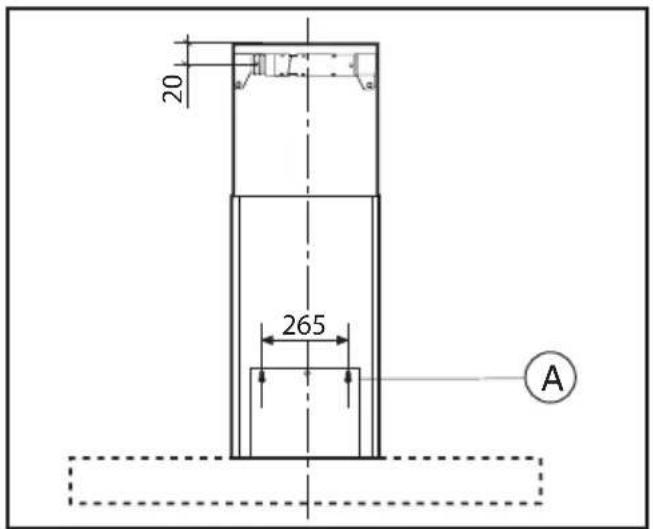
Fig.1
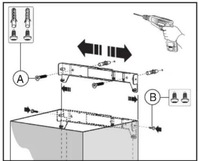
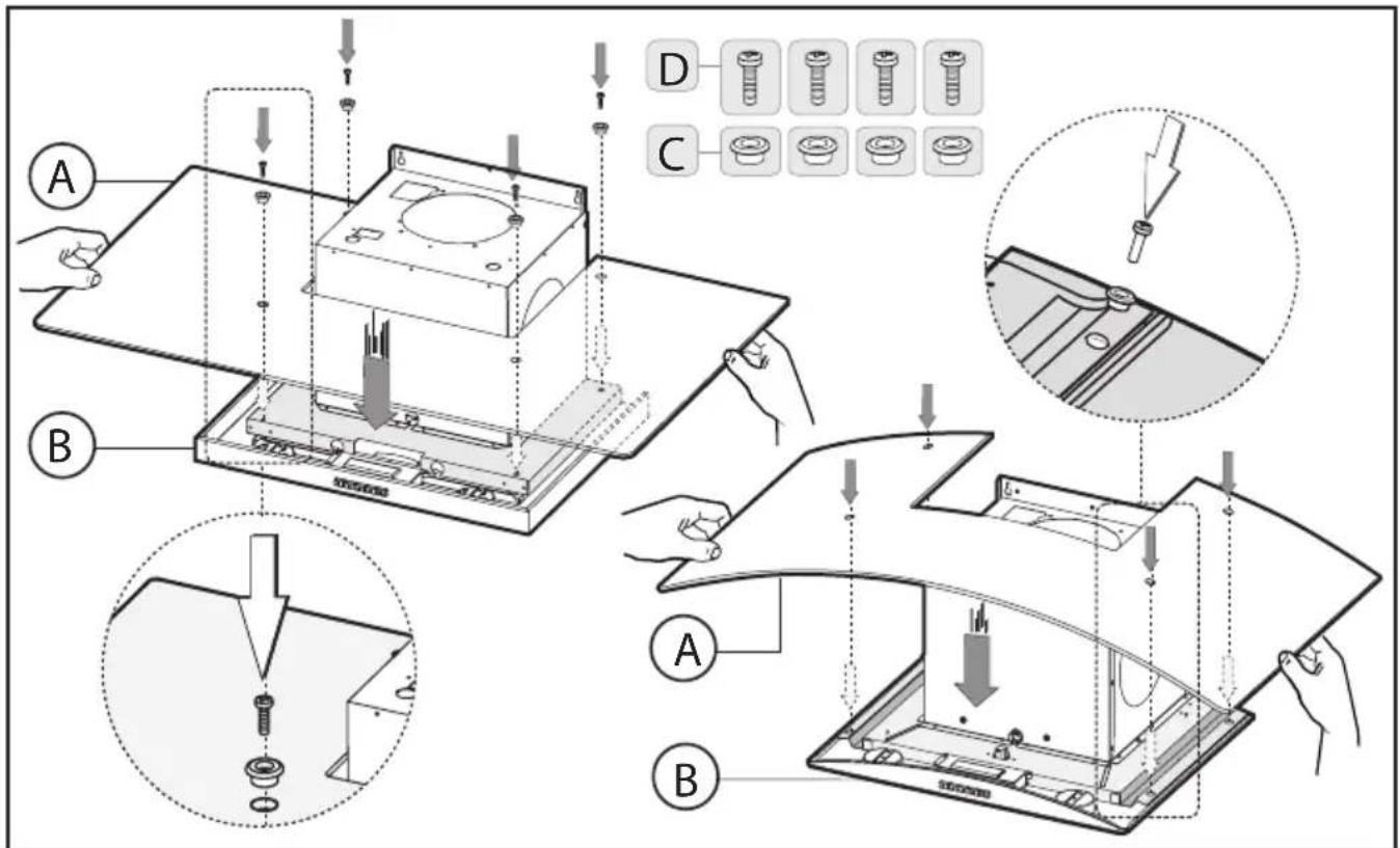
Fig.2 Fig.3
Fig.4
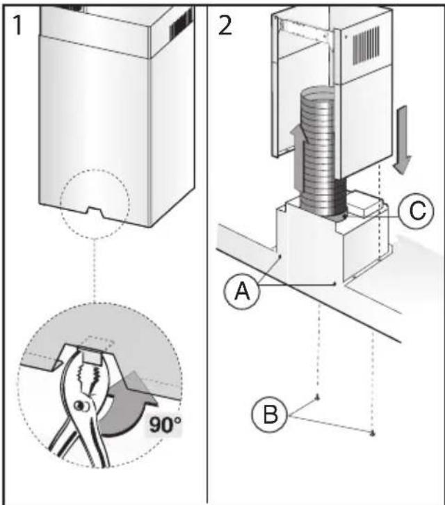
Fig.11
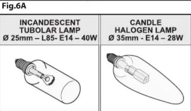
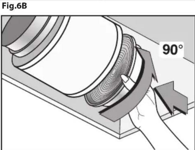
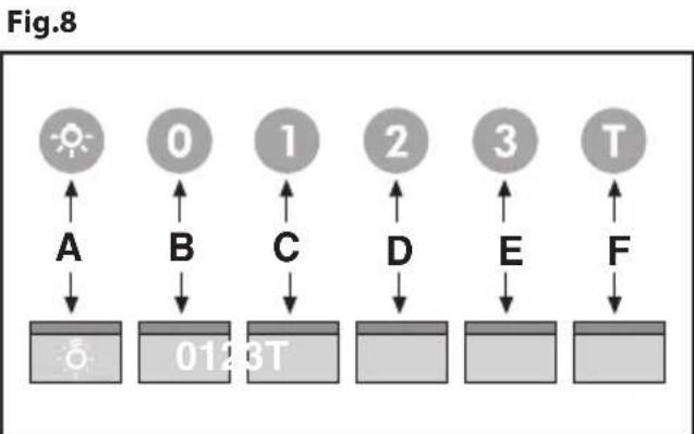
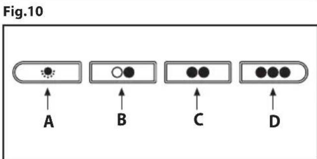
Fig.12
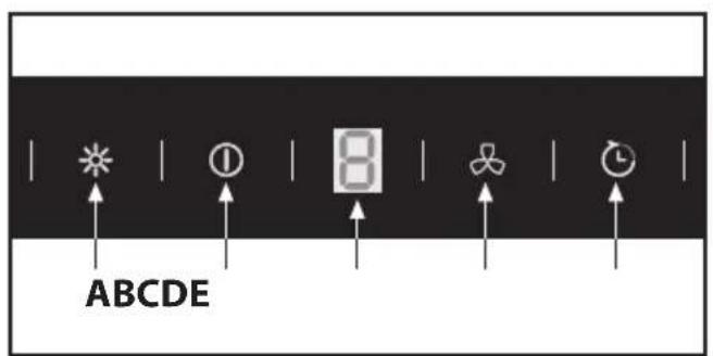
Fig.13 Fig.14
ITALIANO

GENERALITA
- Commandes (Fig.14):
A = Touche ON/OFF
E = Touche ON/OFF LUMIÈRES
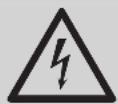
Carefully read the following important information regarding installation safety and maintenance. Keep this information booklet accessible for further consultations. The appliance has been designed for use in the ducting version (air exhaust to the outside - Fig.1B), filtering version (air circulation on the inside - Fig.1A) or with external motor (Fig.1C).
SAFETY PRECAUTION
- Take care when the cooker hood is operating simultaneously with an open fireplace or burner that depend on the air in the environment and are supplied by other than electrical energy, as the cooker hood removes the air from the environment which a burner or fireplace need for combustion. The negative pressure in the environment must not exceed 4Pa (4x10⁻⁵ bar). Provide adequate ventilation in the environment for a safe
operation of the cooker hood.
Follow the local laws applicable for external air evacuation.
Before connecting the model to the electricity network:
- Control the data plate (positioned inside the appliance) to ascertain that the voltage and power correspond to the network and the socket is suitable. If in doubt ask a qualified electrician.
- If the power supply cable is damaged, it must be replaced with another cable or a special assembly, which may be obtained direct from the manufacturer or from the Technical Assistance Centre.
- This device must be connected to the mains supply through either a plug fused 3A or hardwired to a 2 phase spur protected by 3A fuse.
2. Warning!
In certain circumstances electrical appliances may be a danger hazard.
A) Do not check the status of the filters while the cooker hood is operating.
B) Do not touch bulbs or adjacent areas, during or straight after prolonged use of the lighting installation.
C) Flambé cooking is prohibited underneath the cooker hood.
D) Avoid free flame, as it is damaging for the filters and a fire hazard.
E) Constantly check food frying to avoid that the overheated oil may become a fire hazard.
F) Disconnect the electrical plug prior to any maintenance.
G) This appliance is not intended for use by young children or infirm persons without supervision.
H) Young children should be supervised to ensure they do not play with the appliance
I) There shall be adequate ventilation of the room when the rangehood is used at the same time as appliances burning gas or other fuels.
L) There is a risk of fire if cleaning is not carried out in accordance with the instructions.
This appliance conforms to the European Directive EC/2002/96, Waste Electrical and Electronic Equipment (WEEE). By making sure that this appliance is disposed of in a suitable manner, the user is helping to prevent potential damage to the environment or to public health.

The symbol on the product or on the accompanying paperwork indicates that the appliance should not be treated as domestic waste, but should be delivered to
a suitable electric and electronic appliance recycling
collection point. Follow local guidelines when disposing of waste. For more information on the treatment, re-use and recycling of this product, please contact your local authority, domestic waste collection service or the shop where the appliance was purchased.
INSTALLATION INSTRUCTIONS
Assembly and electrical connections must be carried out by specialised personnel.
- Wear protective gloves before proceeding with the installation.
Electric Connection:
- The appliance has been manufactured as a class II, therefore no earth cable is necessary. The plug must be easily accessible after the installation of the appliance. If the appliance is equipped with power cord without plug, a suitably
dimensioned omnipolar switch with 3mm minimum opening between contacts must be fitted between the appliance and the electricity supply in compliance with the load and current regulations.
- The connection to the mains is carried out as follows:
BROWN = L line
BLUE = N neutral.
-
The minimum distance between the support surfaces of the cooking pots on the cooker top and the lowest part of the cooker hood must be at least 65~cm . If a connection tube composed of two parts is used, the upper part must be placed outside the lower part. Do not connect the cooker hood exhaust to the same conductor used to circulate hot air or for evacuating fumes from other appliances generated by other than an electrical source. Before proceeding with the assembly operations, remove the anti-grease filter(s) (Fig.7) so that the unit is easier to handle.
-
In the case of assembly of the appliance in the suction version prepare the hole for evacuation of the air.
-
We recommend the use of an air exhaust tube which has the same diameter as the air exhaust outlet hole. If a pipe with a smaller diameter is used, the efficiency of the product may be reduced and its operation may become noisier.
Please note:
If your version of the appliance has decorative glass before installing the hood, carry out the following steps as shown in figure 4:
1 - Remove both the cooker hood body B and the glass panel A from the packaging and place them horizontally on a secure surface.
2 - Take the glass panel A and position it above the cooker hood body B.
3 - Fix the glass panel securely to the cooker hood body using the 4 sleeves C and 4 screws D as indicated.
Fixing to the wall
Drill the holes A respecting the distances indicated (Fig.2). Fix the appliance to the wall and align it in horizontal position to the wall units. When the appliance has been adjusted, definitely fix the hood using the screws A (Fig.5). For the various installations use screws and screw anchors suited to the type of wall (e.g. reinforced concrete, plasterboard, etc.). If the screws and screw anchors are provided with the product, check that they are suitable for the type of wall on which the hood is to be fixed.
Fixing the decorative telescopic flue
Warning! Caution! If your appliance model features the lower connector with a tab, before fixing it in place bend the tab inwards using a pair of pliers, as illustrated in figure 5, step1. Arrange the electrical power supply within the dimensions of the decorative flue. If your appliance is to be installed in the ducting version or in the version with external motor, prepare the air exhaust opening. Adjust the width of the support bracket of the upper flue (Fig.3). Then fix it to the ceiling using the screws A (Fig.3) in such a way that it is in line with your hood and respecting the distance from the ceiling indicated in Fig.2. Connect the flange C to the air exhaust hole using a connection pipe (Fig.5 - Stage 2). Insert the upper flue into the lower flue. Fix the lower flue to the hood using the screws B provided (Fig.5 - Stage 2), extract the upper flue up to the bracket and fix it with the screws B (Fig.3). To transform the hood from a ducting version into a filtering version, ask your dealer for the charcoal filters and follow the installation instructions.
- Filtering version
Install the hood and the two flues as described in the paragraph for installation of the hood in ducting version. To assemble the filtering flue refer to the instructions contained in the kit. If the kit is not provided, order it from your dealer as accessory. The filters must be applied to the suction unit positioned inside the hood. They must be centred by turning them 90 degrees until the stop catch is tripped (Fig.8).
USE AND MAINTENANCE
- We recommend that the cooker hood is switched on before any food is cooked. We also recommend that the appliance is left running for 15 minutes after the food is cooked, in order to thoroughly eliminate all contaminated air.
The effective performance of the cooker hood depends on constant maintenance; the anti-grease filter and the active carbon filter both require special attention.
- The anti-grease filter is responsible retaining the grease particles suspended in the air, therefore it is subject to clogging with variable frequency according to the use of the appliance.
- To prevent the danger of possible fires, at least every 2 months one must wash the anti-grease filters by hand using non-abrasive neutral liquid detergents or in the dishwasher at low temperatures and on short cycles.
- After a few washes, colour alterations may occur. This does not give the right to claim their replacement.
- The active carbon filters are used to purify the air that is sent back into the room and its function s to mitigate the unpleasant odours produced by cooking.
- The non-regenerable active carbon filters must be replaced at least every 4 months. The saturation of the active charcoal depends on the more or less prolonged use of the appliance, on the type of kitchen and on the frequency with which anti-grease filter is cleaned.
- Regenerable active charcoal filters must be washed by hand, with non-abrasive neutral detergents, or in the dishwasher at a maximum temperature of 65^ (the washing cycle must be complete without dishware). Remove excess water without damaging the filter, remove the plastic parts, and let the mat dry in the oven for at least 15 minutes approximately at a maximum temperature of 100^ . To keep the regenerable charcoal filter functioning efficient this operation must be repeated every 2 months. These must be replaced at least every 3 years or when the mat is damaged.
-
Before remounting the anti-grease filters and the regenerable active charcoal filters it is important that they are completely dry.
-
Clean the hood frequently, both internally and externally, using a cloth dampened with denatured alcohol or neutral liquid detergents that are non abrasive.
-
The lighting .system is designed for use during cooking and not for the prolonged general lighting of the room. The prolonged use of the lighting system significantly decreases the average duration of the bulbs.
- If the appliance is equipped with courtesy lights it is possible to use them for general room lighting for a prolonged amount of time.
- Attention: the non compliance with the hood cleaning warnings and with the replacement and cleaning of the filters entails risk of fires. One therefore recommends keeping to the suggested instructions.
- Replacing halogen light bulbs (Fig.6A):
To replace the halogen light bulbs B, remove the glass pane
C using a lever action on the relevant cracks.
Replace the bulbs with new ones of the same type. Caution: do not touch the light bulb with bare hands.
- Replacing the halogen/incandescent lamps (Fig.6B): Only use lamps of the same type and wattage installed on the device.
- Commands (Fig.9) mechanical the key symbols are explained below:
A = LIGHT
B = OFF
C=SPPEEDI
D = SEED II
E = SPEED III.
- Commands luminous (Fig.10) the key symbols are explained below:
A = LIGHT
B=OFF
C=SPPEEDI
D= SPEED II
E = SPEED III
F = AUTOMATIC STOP TIMER - 15 minutes (*)
If your appliance does not have the INTENSIVE speed function, press key E for two seconds and it will be activated for 10 minutes after which it will return to the previously set speed. When the function is active the LED flashes. To interrupt it before the 10 minutes have expired press key E again.
By pressing key F for two seconds (with the hood switched off) the "clean air" function is activated. This function switches the appliance on for ten minutes every hour at the first speed. As soon as this function is activated the motor starts up at the first speed for ten minutes. During this time key F and key C must flash at the same time. After ten minutes the motor switches off and the LED of key F remains switched on with a fixed light until the motor starts up again at the first speed after fifty minutes and keys F and C start to flash again for ten minutes and so on. By pressing any key for the exclusion of the hood light the hood will return immediately to its normal functioning (e.g. if key D is pressed the "clean air" function is deactivated and the motor moves to the 2nd speed straight away. By pressing key B the function is deactivated).
(*) The "AUTOMATIC STOP TIMER" delays stopping of the hood, which will continue functioning for 15 minutes at the operating speed set at the time this function is activated.
-
Anti-grease/active charcoal filters saturation:
-
When the A key flashes with a 2 second frequency the anti-grease filters must be washed.
-
When the A key flashes with a 0.5 second frequency the active carbon filters must be replaced or washed depending on the type of filter.
Once the clean filter has been put back one must reset the electronic memory by pressing the A key for approximately 5 seconds until it stops flashing.
- Commands (Fig.11):
Push-button A = On/off lights switch.
Push-button B = On/off cooker hood switch. The appliance switches on at speed level 1, If the cooker hood is on depress the push-button for 2 sec. to switch off the cooker hood. If the cooker hood is at speed level 1 it will not be necessary to depress the push-button to switch the cooker hood off. Decreases the motor speed.
Display C = Indicates the motor speed level selected and activates the timer.
Push-button D = Switches on the cooker hood. Increases the motor speed. Touching the key at 3rd speed, the intensive function runs for 10' , then the appliance goes back to work at the original speed. During this function the display blinks.
Key E = The Timer times the functions on activation for 15 minutes, after which they are switched off. The Timer is deactivated by re-pressing Key E. When the Timer is activated the decimal point must flash on the display. The Timer cannot be activated if the intensive speed is functioning.
The "clean air" function is activated by pressing key E for 2 seconds when the appliance is switched off.
This switches the motor on for 10 minutes every hour at the first speed.
During functioning a rotary movement of the peripheral segments must be visualised on the display. When this time has passed the motor switches off and the fixed letter "C" must be visualised on the display until the motor re-starts after 50 minutes for another 10 minutes and so on. Press any key apart from the light keys to return to normal functioning. Press key E to deactivate the function.
Active carbon/grease filter saturation:
-
When display item C flashes, at a speed where it alternates with the letter F (e.g. 1 and F), the grease filters must be washed.
-
When display item C flashes, at a speed where it alternates with the letter A (e.g. 1 and A), the active carbon filters must be replaced or washed depending on the type of filter.
After the clean filter has been positioned correctly, the electronic memory must be reset by pressing button A for approximately 5 seconds, until the indication F or A shown on the display C stops flashing.
- Mechanical controls (Fig.12): the symbols are as follows:
A=LIGHT/ON-OFFkey
B=OFF/FIRST SPEED key
C=SECOND SPEED key
D = THIRD SPEED key
If the hood is shut off at first, second or third speed, when it is turned back on, it will start at the same speed it was in when switched off.
- Commands (Fig.13):
A = Light Key Turn on/off lights.
B = ON/OFF Key Turn on/off the hood.
The equipment switches on at the 1st speed.
To turn off the hood press key B.
C = Display Indicates the speed of the selected motor and activation of the timer.
D = Key Increases and decreases the speed of the motor with a cyclical pattern, 1^ - 2^ - 3^ 1^ - 2^ - 3^ speed.
By pressing the key for 3 seconds the INTENSE function comes into operation for 6 minutes, on the C display the number 4 starts flashing.
At the end of the minutes the engine will start operating at the previously set speed.
To deactivate the intense speed, before the set time, press the B key and the hood turns off, but not if the lights are on.
E = Timer key With any speed entered (excluding Intense speed) by pressing the key the timer function is activated for 15min . At the end of the count the hood turns off (motor and any lights that are on).
To turn off the Timer function, before the pre-set time, press
the B key and the hood turns off, or by pressing the timer key again it turns off but the hood continues to operate.
- Saturation Active carbon/Anti-grease filters:
- After 30h of operation, with the hood ON on display C, the letter F starts to flash which means that the anti-grease filters have to be washed.
Once the clean filter is replaced you must reset the electronic memory, with the hood off press key B and D for 5 sec. until the display C shows the letter F fixed for 2 sec.
-After 120h of operation, with the hood ON on display C the letter C starts to flash which means that the carbon filters have to be washed or replaced.
Once the clean filter is replaced you must do a double re-set so with the hood off press key B and D for 5 sec. until the display C shows the letter F fixed for 2 sec.
Repeat and press key B and D for 5 sec. until display C shows the letter C fixed for 2 sec..
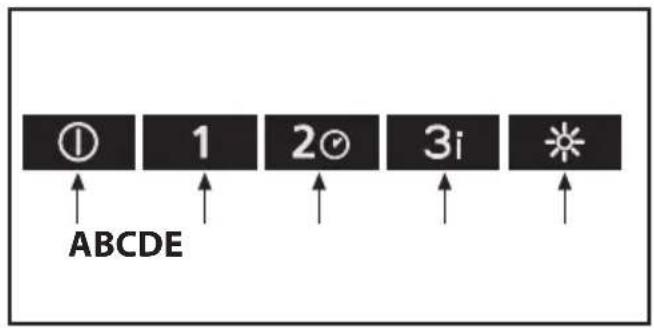
- Commands(Fig.14)
A = ON/OFF key
Turns the hood on/off.
By pressing key A the LED flashes for 2 sec. then remains fixed and the equipment starts in 1^ speed.
To turn the hood off press key A again, the LED flashes for 2 sec. then it turns off.
B = FIRST SPEED KEY
C = SECOND SPEED Key/TIMER function
- Key C also activates the TIMER function.
- The key flashes for the full duration of the TIMER.
- With any speed entered (excluding Intense speed where applicable) by pressing C for about 3 seconds the TIMER function is activated for 15min . At the end of the count the hood turns off (motor and any lights that are on).
- To deactivate the Timer function, before the pre-set time, press any key except the F key for ON/OFF Lights.
D = THIRD SPEED key/ INTENSE SPEED Function
- Key D also activates the INTENSE SPEED function.
- The key flashes for the full duration of the INTENSE SPEED function.
- By pressing the key for 3 seconds the INTENSE function comes on for 6 minutes.
- At the end of the minutes the engine will start operating at the previously set speed.
To deactivate the intense speed, before the pre-set time, press any key except the F key for ON/OFF Lights.
Attention! Some models only work up to the 3rd speed and, therefore, do not have the intense function.
E=ON/OFFLIGHTSkey
- Saturation Active carbon/Anti-grease filters:
- When the hood is on the LED corresponding to the A and B keys flash, the anti-grease filters must be washed.
Once the clean filter is put back the electronic memory must be reset, with the hood off press A for 5 sec., the reset is confirmed by a flashing of the LED A and B. - When the hood is on the LED corresponding to C and E flash, the carbon filters must be washed.
Once the clean filter is put back the electronic memory must be reset, with the hood off press A for 5 sec., the reset is confirmed by a flashing of the LED C and E.
THE MANUFACTURER DECLINES ALL RESPONSIBILITY FOR EVENTUAL DAMAGES CAUSED BY BREACHING THE ABOVE WARNINGS.
ALGEMEEN
INSTALLATIE INSTRUCTIES
$$ \mathbf {A} = \text {k n o p L I C H T} $$
$$ \mathbf {B} = \text {k n o p U I T} $$
$$ \mathbf {C} = \text {k n o p E E R S T E S N E L H E I D} $$
D = knopTWEEDW DERDESNELHEID
E = knop DERDE SNELHEID.
D = knop TWEDW DERDE SNELHEID
E = knop DERDE SNELHEID
F = knop TIMER AUTOMATISCHE ONDERBREKING na 15 minu-ten (*)
Commando's (Fig.13):
Commando's (Fig.14):
A = ON/OFF-toets
MARROM Linha
AZUL = N neutr.
Tecla A = Acende/apaga as luzes.
A = Tecla Luzes Liga/desliga as luzes.
B = Tecla ON/OFF Liga/desliqa o exaustor.
Zapne/vypne digestor.
C= tast for ANDEN HASTIGHED
D = tast for TREDJE HASTIGHED
B = Tast FØRSTE HASTIGHED
E=VALOJEN ON/OFF-painike
$$ B A R N A = L f a z i s $$
$$ \mathrm {K E K} = \mathbf {N} \text {n u l l a f a z i s}. $$
A = tast for BELYSNING
B = tast for OFF (AV)
C = tast for FØRSTE HASTIGHET
D = tast for ANNEN HASTIGHET
E = tast for TREDJE HASTIGHET.
A = tast for BELYSNING
B = tasting for OFF (AV)
C = tasting for FØRSTE HASTIGHET
D = tast for ANNEN HASTIGHET
E = tast for TREDJE HASTIGHET
F = tast TIDSURE AUTOMATISK STOPP 15 minute (*)
A= tast for LYS/ON-OFF
B= tast for OFF / FØRSTE HASTIGHET
C= tasting for ANDRE HASTIGHET
D = tast for TREDJE HASTIGHET
Hvis hetten slukkes nár den er plassert på förste, andre aller tredje hastiget, vil den starte ved samme hastiget när den slås på igjen.
- Kommandoer (Fig.13):
A = Lystast SIar lysene pa/av.
B = ON-/OFF-tast Slar ventilatorhetten på/av.
Enheten slas pa i 1. hastiget.
MEPbI INPEOCTOPOXOCTN
1.БытВьHMaTeNbHbIM,ecnOДHOBpeMeHNo pa6oTaET BblTЯKKa n RopeJIka nIN Oyar,HxJIAIOUneC B OKpyXaIOUeM BO3dYxe N 3aIITbIBaIOUneC nHOn 3HeprNei, KpOME 3JIeK-TPueeCKoN.
B Takom cnyuae BbTjKka ydaJnE n3 nomeHnBaO3dyx, HxKhbl nI npouecca crotpana B ropEnke nn ouare. OtnpuacnbHoe daBHeHne B nomeHn He dOnkHo npeBbIwAtb 4Pa (4× 10^-5 bar). INa HndekHO n6e3onacHO pa6oTb cIeDyet o6ecneuHTb BeHTnlaunIO nomeHn. IJa HApXKnBix Bbl6pocOB co6NIOaTb npabIna, deIcTBYIOue B BaWeI cTpaHe.
PpeJeHemnoKIOuHTb np6Op K3eKtpuecko cTeN:
- Y6eIbBcB COOTBeTCTBnHAnpJxHeHn MOnuHocTn npi6opa,daHbIe O KOtOpbIX NOMeUeHbI Ha 3aBOdCKo NacNoptHo Ta6nUke, cTeBBIM NOKa3aTeJam, a TaKKe COOTBeTCTBne 3JeKtpocoeDHNHTeJI(p03eKn).B Cnyae HeCOOTBeTCTBnpo3eTKn 6paTbC K KBaINΦuNpOBaHHOMy 3JeKTPnky.
- Ecn npoBOD 3neKtpOnHnN NOBpeXeH, 3aMeHnte erO nIN BeCb CneuaNbHbY3eY I pON3BOuNTeR NIN B yNONHOMOueHHOM LcHTpe TexHueeCKOrO OcbnykBaHn.
- PoiocoeiHHTy yCtpoIcTBO K cTeu 3neKtpoNtHaHnno nOcpeCTBOM wTeencelbHO BUNK C npdeoxpaHnteMe 3 A nnDByx DByxNONIOChbIX npOBODC npdeoxpaHnteMe 3 A.
2. Bhumane!
B HeKOTOpbIX CnyaX 3JIeKTPnueckne npu6Opbl MoryT 6bIb onachbIMU.
A) He npoBepaIte coCTOHNHe nIbTPOB npn pa6oTaUoSei BbITAAKke.
B) He npnkaaTecb K lamnoqkam nnn K npnneraozmm 30HAMBnpocece pa6oTBICNTemblOCbeueHn nn cpa3y Xe nocle ee BbIKIOUeHn.
C) 3anpeucaetra roTOBntb 6nOda Ha oTKpbTOM nIaMeHn NOd KxOHHO BbITAKKo.
D) 36eAte OTKpbITOro nIaMeHn, TAK KAK OHO nobpekJaet HbTpbl MoKeT npBecTn K BO3ROPaHIO.
E) B npoecce xapkn BO pputope HnpepbIBHO cneinte 3a npocccom Bo n36exahme BO3ropaHne Knnraero macna.
F) OToCoeMnHnIte WTeNcBHyIO BnKy OT cTeBOu po3eTKn npeD hauAnOM TexHmueCKOrO 6cbnyKbAHn.
G)I3dennHe paacuTaHo Ha 3Kcnnyatauio DeTbMn nn Heedeecnoc6hblm nlaamn 6e3 KOHTpOra.
H) He pa3pewaTe DeTm mIgpaTb c n3dennem.
I) EcnBbTJXKa NcNoJIb3YeTcOdHOBpeMeHHoCdpYnMM np6OpamN, B KOTopbIX NcNoJIb3YeTc TOnJIbHBhI ra3 mN dpyrne BNdbI TOnJIbA, B NOMEeHNn DonxHa 6bITb oEcecneHa HndexkaaJa BeHTnlaun.
L) B cnyae BbInonHeHH onepaun no qnCTke 6e3 co6NIOH HNCTpyKcun cyueCTBye TOnaCHOCTb BO3ROPaHH.
JaHHoe n3dEne ImeemT MapKnupOBky COOTBeTCTBna EBponeckomy Hopmatby 2002/96/EC, Ytunn3aunr 3eKtpnueecknx n 3JeKtpoHbIX n3deNn (WEEE). PpoBepbTe, yTO6bl no OKOHuaHn erO cPoka cnYk6bl DaHHoe n3dEne 6blIO cdaHO BytNB. 3TmBbl nomoxkeTe coxpaHntb OkpykaIouyU cpey.

CnBON Ha n3dennnn B npnnaaroue c K Hemy DOKymentaun O3Haayet, YTO daHHO n3dne He dOJXHO paccMaTpuBaTbcra KaK 6bITOBbl eOTxoDbI, a DOJXHO 6bITb CdaHO BcneuaabHbI ueHTpyTNnnaucn,
3aHIMaIOuINc yHnHTOKeHHem 3neKTPnueckcxn n 3neKTPoHNbIX np6OpOB. H3denne doJXHO 6bITb CdaHO BytNtB B COOTBeTCTBmC MeTHbIMn HopMaTnBaMn NO yTUNI3aUIN OTxODOB.3a DOnONHInTeNbHbIMn CBeDEHnA M KacaTeNbHO 6pa6oTKn, yTNlIN3aUIN uYHNTOKeHHaDHORIO n3DeNnra O6paauTecB M MeCTHO otDeHnE c6opa DOMaUnHX 6bITOBx np6OpOB INN B MaRa3IN, B KOTOPOM 6blIO KyPHeHO n3dennie.
HCHTPKUNIPOYCTAHOBKE
- MoNTaX N 3JIeKTpUeCKoe NOJKNIOueHne DOJXHbI BblNONHbCTKBAJIINΦUUPOBAHbIM TEXHMKOM.
- Ipeed Tem, KaK npucTyuNTb K MOHTaXHbIM onepaunm, HadeTb 3auuTHbIe nepuaTkn.
-3neKtpnuecka CB3:
Heo6xOIMO o6ecneuHT b IerKn IocTyn K WTeNCeIIO noCne yCTaHOBKn annapata. B Cnyue nocTabKn annapata c Ka6eJem 6e3 wTeNCeJI, dIy TORO YTO6bI NOkKIOUHTb eRO K 3JeKTPnuEckOcETn, Heo6xOIMO yCTaHOBNTb MekJy annpapatOM n CeTbIO MybTINOpIrpHbI BbIKNoHaTeJIb C MHNMaNbHbIM paccToHMeM MeKdy KOtAKTaMn 3 MM, paCCHTaHHbI Ha daHHyIO Harpzky N COOTBeTCTByIOuN DeNCTBYIOUM HOPMaTnBaM.
KOpHHeBbI-L-JINHHa
CUNHIN-N-HeITpAlHBII.
MInHmAlbHaNtCTaHcHmEckNyOnOpHoH HArpeBaIOUeCn PIIOCKCTbIO N HIXKHeu CaTbIO KxOHHOrO DbIMOCoA DOJXHa 6bITb He MeHee 65cm.EcnI npImeHReTCs CoeHNHTeBHa Tpy6a n3 DByX N BoJe e TaCTe, To BepHra Uactb DoJXHa paCnOLarTaBCn ChApYKn HIXKHeu CACTn. He CoeHNrTB Bbl6poc N3 BBtJkNN C KaHAnOM LcPkyIaIuR ropayero BO3Dyxa nn C KaHAnOM, INcNoJIb3YeMbIM dIg OTbOda DbIM OYCTPOiCTB, 3aNbITbIAebMbx INHOh 3HeprnEe KpOME 3NeKTPnuueCKoi. PepeT E M KAPnCTyNTb K c6OpKe yCTpoiCTBa, dIg ObnerueHn erO MoHTaKa OTcoeINHtE fNlbTp/JkpOyNaIBaIOUuNf NInbTp (Pnc.7).
B TOM CNYue, ecnn npn6op MOHTnpyetcC BbITKhbIM yCTpOINCTBOM, peKOMEHyETcO bcneuHb NomeeHne Bbl
BOHbIM OTBepCTnEM.
- Pe KOMeHdyETcA nCnONb3OBAbT py6y DbIMOXoJa C TaKIM Je dIaMeTpOM, yTo N OTBepCTne nOaun BO3Dyxa. NcNOnb3OBAHHe cyKeHHo Tpy6b MoKeT cOKpaTntb KПД BbITJxKn I yBeINuHTb ee WymOBOy yPoBeHb.
BHUMAHNE!
EcIn BercnBaWero n3dennyKoMnneKToBaHa deKopataBHBbIM CTeKlOM, nepe MoHTaXOM BbITaKKn Heo6xOJIMBOBINOHNtB Oepaun, NOKa3aHHbIe Ha pucynke 4:
1- DocTaTb n3 ynaKOBKn KOpnyc KOnJaKa B u cTeKnO A u pa3MeCTnTb nX B rOpn3oHTaNbHOM NpIoXKeHn Ha npOuHoN IOBepxHOCTn.
2-B3aTb CTeKNo A n pa3MeCTnTB erO Ha Kopnyce KOnnaka B. 3-3aKepeNTb OKOHyATElbHO CTeKNo HA Kopnyce KOnnaka c nOMoUbIO 4Btynok Cn 46oNtOB D, KaK yKa3aHo Ha pucyHke.
- PnpKpenHeNk CTeHe:
BbINHnTe OTBepCTnA,co6NIOaYka3aHHbIe paCCToHnA (Pnc.2).PpIKpeNTe ycTpoiCTBO K cTeHe npn NOMOuPerpyIpuyEmoRO kPoHtEHa,BbIPOBHnTe ycTpoiCTBO BROPHTaJIbHOM NIOXeHN. PpIKpeNTe OKOHaTeJIbHO KOJNAK DByMa BVHTaMn A(Pnc.5).B 3abCmOCTnOT BapNaHTaMOHTaxa NcONb3yIte BNHTbl (Wypyn) n IIO6eNN, COOTBeCTByUOune TIny CTehbl (HaNPIMep, JKeJe3o6eTOH, rINCOkAPtoHnT..EcnBnHTbl nIO6eBNxOaR T KOMNJEKT NOCTABKn, CNeDyET yOcOToBepuTBcB TOM, YTO OHN NOxOaR T DnToro TIna CTehbl, Ha KOTopoN dONXeH 6bITb CMOHTnpoBaH KOJNAK.
- MoHTaX DeKOpaTHBbIX TeneckOnnuecknx c6OpOuHbIX 3JeMeHToB:
BhImaHne! Ecm MoIb BaIero annapaTa HmeeT HnKHee coEiHHeHne 3bIyKOM, npexde Yem pncTyNtB K 3akpePnEHHo, 3aXBaTIte HnKHee CoeHNHeHne n npn NMOU uINuOB HaKnOHHe TcBbO BbHTpb, KaYka3aHO Ha Pcsynke 5 3tan 1. PpeBapntelbHO BblONHte NOBODky 3NeKTpOpnoBod BHyTpN DeKopaTHBHO c6bpOuHoro 3emeHa. Ecnn BaWe yCTPOINCTBO YCTAHNBaeTcKa K BblTAAHoe NnC HapyKhbM 3NeKTPOINrTeJeM, PpeBapntelbHO CdelaNte OTBepCTne DnA OTBDA BO3dyxa. Otperynpyte Wnpiny NOnDepxNBAIOJero KPOH WTeHa BepxHero c6bpOuHoro 3emeHa (Pnc.3). Pprkpennte ero Knotonky BInrTaMn A TaK, UTo6bl ObecneuTbe erocochoctc B CaIIM KOIIaKom (Pnc.3), co6lioua paCCTOHne ot NotoLka, yKa3aHHe Ha Pnc.2. CoeHNHTe flaheuC C OTBepCTnE M Ira BBBeDeHn BO3dyxa NocpeDCTBOM CoeHNHTeBHO Tpy6bl (Pnc.5).
BctaBbTe BepxHn c6oOpHbI 3JeMeHT B HxHn. PpKpeNITe HxHn C6opOHy bI 3JeMeHT K KOINaKy, INcNOb3yB BuHTb B, KOTOpbl e pInnaRaIOTcra (Pnc.5), CmecTne BepxHn C6oOpHbI 3JeMeHT DO KPOHHTeHa N PpKpeNITe erO BuHTAMn B (Pnc.3). IJI npEbpauSeHn KOnNaKa n3 BbITXHO B fNtpyuO u6paTntecb K CBOemy DInepy dJa NOnyuEHn FInbTpOB CaKTbUpoBaHHbIM yTJEM m CNeDyIte INHCTpyKUINM NO YCTaHOBKe.
- Kolnak B BapnaHTe ΦиьТуpoUeYoуctPoNCTBa:
yctaHOBtTe KOJInak INBa c6bOpOHbIX 3IeMeHtA KaK yKa3aHO B pa3JeIe NO c6bOpKe KOJInaka B BapnaHTe BbITXKnHO yCTpoiCTBa.ДЯc6opKNФINbTpUOJero 3IeMeHtA CNeDyIte INCTpyKUIM, COePJAuMmCB KOMNKeTpe PpHaIeXHoCTe. EcIn KOMNKeT OTCYCTByET, 3aKaJntE rO DOnONHtEnbHO y CBOero dIepa.ΦINbTpbl DOJHXbl 6bITb NOMEeHb Ha BCabIBAIOoee YCTPOICTBO, PaCNOJoxEHoe BO BHYTpENHe YAcTHN DbIMOCoca. YCTaHOBtB ΦINbTpbl CTporo No CEHTpy IN 3aTe M NOBepHyTB Ha 90 rpaDycob Do 5eJyka (Pnc.8).
3KCNJYATAUINI TEXXOD
- Pekomehnyem BBectn annapat B kcnnyataunio, npexde yem npctyntb K Bapke kaKoro-n6o 3nemeHa. Pekomehnyem octabntb pa60TaB annapaT ha 15 MNHT, nocce 3abepeHnra npiroTOBHeHnIu, qTO6bl NOJIHOCTbO BblNCTb TReKeIbI BO3dyx. XopoOee fHKUHOHPOBaHne KOJInaka o6cNoBHeNO npABNbHbIM INoCToAHbIM TEXHNueCKMm O6CnJXNBaHneM; Oc6oe BHHMaHne CnEpy TeJEnTb fNtpy Jknpa N aKTNBPOBaHHOro yTnA.
Knpoydaiououn fnbTp dOnKeH yepKNaBt b KnpHbE B3BeWeHHbe YactNUcBi B 03dyX, cJeIOBaTeNbHO, ero 3a- rpa3HeHne 3aBucNT OT BpeMeHn pa6Obl np6opa.
-Bo n36ekaHne pncka noKapa, Hepeke DByx pa3 B MecaIe H06xoJIMo IpombIbT b KInpoUdAIAIOUIne fNJIbTpblBpyHyIO CnOJIb3OBaHmE KINkIX HeITpaJIbHbIX MOIOUX cPeIDCTB 6e3 a6pa3UNBbIX Do6abOK, INI Mblb B NocydomOoeHoi MaunHKe PnHn3KOI TemnepaType IN B KopoTKne ZIKNbl.
- Lbet MoKet n3MeHHTbCn, Nocne HeckoJbKnx IpombiBOK. 3TOT aKT He daeT npaba Ha XaIoo6y u 3ameHy Detanu.
-ФньрсakTNBnpoBaHHbIM yrnm Heo6xOДmbl dny OUcTkn BO3Dyxa B NOMEueHn U ydaJIaIOT HENpNTHbIe 3a- naxn npnnproTOBHeHn nii.
- He perehepnpyemble funbtpbcaKTnbupoBaHbIM yIeM He 06xodnmo 3aemeHbHepeke 1 pa3a B 4 mecaua. HacbiueHne AKTNBUPOBaHHORO yrJra 3aBNCIT OT TORO, cacto nCNoJIb3OBaJIcR npu6op,OT Bnda KuxHn N O T peryIpaHocTOn OuncTKn JkpoyDaIauIOUeO funbTppa.
-Pereheepuymbee nIbtpb cakTNBnpoBAHHbIM yIeMe HEO6xOJIMMO bITb BpyHyIO, CICNOLb3OBaHHeM HeITpaJIbHbIX MOUux cpeCTB 6e3abpa3NBbIXdo6aBOK, ININ B NOcyDOMoeHou MaunHe np TemnepaType He Bblwe 65^ (npn ATOM B MaunHe He IONKHO HaxoNTbcra NocyDb).YdaIITb IINHIO BOyHe NOBpekDa fNtbp, ChrTb INaCTMaCCOBbie DeTaNN I BcUYNb KOBpIK B neu, He Mehee Yem 15 MmHT npin TemnepaType He Bblwe 100^. .YTo6bl NoDEpXNBaTb fNtbp Tc AKTUNPOBaHHbIM YIeEM B aΦeKTHBHom COCTOHNN, 3TO OnpauNIO Heo6xOJIMNoPBOIDTp KaXdbie 2 Mecya. He Mehee Yem pa3 B 3 ro da fNtbp Heo6xOJIMo ZAmHArTb, INN KOrDa Ha KOBPnke 6OBapyKeHbIO NBpeKdEHHa.
- Ipeed Tem, KaK yctaHOBntb KInpoydaIoune fHnltpbrn Hnltpblc AKTUBNPOBaHHbIM yrlem, Heo6xOdmo nx TuaTeNbHO BbICyuNTb.
-Heo6xOJMo OaTo OuNua Tb KOnnak KaK BHyTp, TaK m ChapyKn, nCNoB3yra YBlaXkHeHHyIO DeHaTpyPnpOBaHHbIM CnIPTOM TKAHb NII HeITpaJIbHbIe He IapanaIoUne XnIckne MOUcne cpeCTBa.
JaMnbl BbITaKcN CnyKaT dIa OCBeUeHnBapOuHO nAneHIN BO Bpem npiroTOBHeHn Hpe paCHTaHbHa nnTeNbHOE BKIOUeHne DnI O6bUHOrO OCBeUeHn PomeHn. IpOJONXtJIbHOe NcNOb3OBaHne JAMn BbITaXeK 3HaunTeHo COkpaaaet IN cpeHn CpOK CNYK6bl.
- Ecnn npn6op ochaeh OCBeueeHem nOmeuHn, OHO MoKet 6bItb NCNoJIb3OBAHo dIg DInTeJIbHOro pPImHeHn Bcero OCBeueHn NOMEeHn.
BHHMaHHe: HecO6JIIODeHHe peKOMeHdaIIN NO OUHCTKe BbITJAKKe N 3aMeHe IN OUHCTKN ΦNtPOB, PnIBoNDNT K ONACHOCTNI NOXapa. PeKOMeHdyETcA CneIDOBaTb PnIBeEDHHbIM NHCTpyKcIyM.
- 3aMeHa ranoreHHbIX naMn (Pnc.6A):
ДлЯЗмehы raIoreHbIX lamn B CHIMMITE cTeKJIaHHyIO KpbIiKy C, NOДeB ee OTBepTKoB CneuaJbHbIX na3ax.3amEHTE lamMbHa lamMbTaKOrO Xe TIna.
BHMHHe: He npKaacTecb K naMnam roJIbIM pyKaMn.
- 3aMeHa lamnoqun HakaunBaHna/raIoreHHo (Pnc.6B): IcNoJb3OBAtB ToJIbKO lamnoqun TaKOrO Je TUNa N BoJIbTaXa, yTO n yCTaHOBHeHHbE B npIbope.
- Oprahty npablenya (Pnc.9) MexaHueckne:
A=KHOKNKaOCBeUeHn
B=KHOIIKa HUJIeBOI
C=KNHONKa nepBOBCKOPoCTN
D = KHOIIKA BTOPOI CKOPOCTN
E = KHOPIKA TpeTei CKOPOCTN.
- OpraHbI ynpaBHeHn CBTeaunecs (Pnc.10):
A=KNHONKaOCBeUeHHN
B=KNHONKa HynEBOI
C=KHOKNa nepBOB cKOpOCTN
D=KHONKa BTOPOC KOPOCTN
E = KhoNka TpeTei CKOpOCTn
F=KHOIIKa TaIMepa aBbOMaTnueckoN OcTaHOBKn Yepe3 15 MHN (^*)
EcIN B BaIeM yCTpoiCTBe NOkKIOUeHa FyHKUma NHTEHCUBHO CKOpOCTn, Ia ee AKTNaCIN Heo6XoIMMo BKIOuHTb TPETbIO CKOpocTB n depKaTb HkaToB TeueHne npumepHO 2 cekyHd KONky E.3Ta FyHKUma AKTNBpuyetc Ha 10 MNHT, NocJe Yero npOn3oJET BO3Bpat KycTAHOBNeHHo paHee ckopocTu.Bo BpeMa AKTNaCIN FyHKUma Muaet CBEToNDhbi INDnKAtoP. JIg OCTaHOBKn FyHKUma Do nCTeHne 10 MNHT Heo6XoIMMo CHOBa HkaTb KONky E.
BHeKOTopbIX MoedIaX BO3MOxHO aKTUBPOBaTb 3Ty yHKUHO Ha nepBOH BTOPOI CKOPoCTN.
HaKaTOM noIOKeHnB TeueHne 2-X cekyHKnlaBnWy F.ДЯ BKNIOUeHnA yHKcHn "clean air" HaKaTb N DEpKaTb B TaKOM nOIOKeHnKnabNwY F.3Ta yHKcHn exeayacHO BKNIOuaeT bNraTeB Ha nepBOI CKoPocTn Ha 10 MNHT, B TeueHne KOToPbIX DOJXHb MIRa Tb ODHOBpeMeHHO yKa3aTeiN KJIaBnW F n C. Iocne Yero DnRaTeB BBkIOuayetC, a yKa3aTeiN Ha KNaBnWe F ocTaetc3aXkeHHbIM. Ppi6bn3nteBHO uepe350 MNHT ONrB BKNIOuayetc DnRAteB Ha nepBOI CKoPocTn, n yKa3aTeiN F n C HauHnAO T MRaTb B TeueHne 10 MNHT n T.D. Haxmam Ha IIO6byo KhoNky, 3a NCKIOUeHnEM CBeta, BblTJka Bo3BpaaaeTcR K HopMaNbHomy pexKmMy pa6OtB (Ha npImep, npHaKAtTN Ha KhoNky D, OTKIOUaETcFyHKcHn "clean air" n DBnraTeB yCTaHaBnBaEaTCR Ha BTOpyIO CKoPocTb; Haxmam Ha KhoNky B, fYHKcHn OTKIOUaETcR).
(*)Функцу"TAIMEP ABTOMATUeCKO OCTAHOBKN 3aepxNBaeT OKJIIOUeHne BbITXKK, KOTopa IpoJOnJaet pa60Tu Ha cKOpocTN, BbIbpaHHoN npn BkIIOUeHnn 3ToI ΦyHKuIN Upe3 15 MmHyT.
3acopenehe fubtpob-kupoynobutee/foibtpa cAKTNBUPOBAHHbIM yIem:
-Korda Mrraet KONka A c qactoTo2 cek., Heo6xoJIMO BblMbItb 0nIbTpbl- xipooyIOBNTEN.
-Korda Muraet KhoNka A c qactoTo0 0,5 cek. Heo6xOIMO npomblb nIaMeHnTb fIbTp C aKTUBnpOBaHHbIM yIeM, B 3aBucmocTOn OT eRtMa.
Iocne yctaHOBKn Ha MeTO YnCTOro 0nNbTpHa Heo6xOuMo O6HyNTb 3JIeKTPoHHyIO NAMrTb, HaaKAB KHONKy A npImepHn Ha 5 cek. Bnnotb Do npeKpaueHn MraHn.
- OpraHbI ynpaBneHnra (Pnc.11):
KnabmaA A = BKIOUOaET/BbIKIOUOaET NOCBETKy.
KnabuBa B = BKIOueHHe/BbIKIOueHHe BbITaKn. BbITaKKa BkIOUaTcra Ha 1-0i ckOpocTN. EcnBbITaKKa BkIOUeHa, HaxMnte KONky Ha 2 cekyHdbI, yTO6bl BbIKIOuHTb ee. Ecn
BbITKa pa6oTaeHa 1-0n ckOpocTu, He HxKHO depKaTb KONky HaxaTo n en ee BbIKIOueHn. CkOpocTb DnraTeNa COKpaaaetc.
Dncnne C = NOKa3bIBaet CKOpocTb MOTopa, KOTopa 6blNa Ha6paHa, IN BKJIIOHeHne TaIMepa.
KnaBuaD=BkIIOueaET BbITAXKy.YBeINuINBaETCKOpocTbMOtopa.Haxatne KnaBun 3-н ckopocTb Bbl3bIaBcTakINBaUIOOfHKUN INHTECNBHOro pexIMa Ha 10 MmH, NO nCTeeyHNKOtOpbIX BOCCTaHaBNBaETcCKOpocTb pa6Otbl,AKTNBHOBMOMeHT BkIIIOueHn DaHHoN OyHKUn. Ha nepnoI deIcTBnINHTECNBHOro pexIMa IMeet MeCTo MIRaHne INHdNKaTopa.
KnaBnuaE = TaMep Ha 15 MNHyT 3aONMnHaet fYHKUIN B MoMeHT BKIOUeHnI NOcIe OTKIOUeHnI 3TNX fYHKUIN. TaMepOTKIOUaTeC NOBTOPbIM HxATnEM KHOIN E. Korda fYHKUIN TaMep BKIOUeHa, Ha DCNlEE DoJIXHO MIRaTB DEcTNUHoe 3NaueHne. EcIn pa6oTaET INTEHCNBnAckopocTb, BKIOUHTb fYHKUIN TaMep HeNb3ra.
Haxab KhoNky E Ha 2 cekyHdbipn BbIKNoeHHoB bItaKke, BKIOuayetc yHKunra "clean air", 3Ta yHKunBa BKIOUaET dBIRatel Ha 1- on ckopoctn Ha 10 mHyT kaxdyac. B npoucece yHKUNHOPOBaHna Ha nCnnee noka3bIbaOTc BpaauOuuec6 6okOBle cerMeHTb. I no nCTeueHN tTOrO BpemeHn DBrarTeB BbIKNoaETc, H aDnCnnee NOABnEeTC6ykBa C Do cneIyoero 3aNycka DBRATeHa 10 MHyT No npoeeTBm 50 mHyT. UTo6bI BEpyTbcR K HopMaJIbHOJ pa6ote, HaxaTb Ha IIO6yIO KhoNky Kpome ocBeueHry. UTo6bI OTKIOUYt bYHKUNIO HaxaTb Ha KhoNky E.
- 3acopenehe fHbTPOB-KnpooyNoBtene/foHBtpa cAKTNBnPoBAHHbIM yrlem:
-KordaHaDnCnnee CnonepemEnHO MmraIOT 3HaueHne pa6oeyckopoctn n 6yKbaF (Hanpum.,1 n F) Heo6xOaIMMo BbIMbITb fInlbTpbl-KnpooyNoBteiN.
-KordaHaDnCnnee C no nepemehno Mmraot pa6oay cKopocb n 6ykbA A (Hapnpmep,1uA) Heo6xoJIMO 3aMeHntb nnPiPOMblbΦNlBtpbicakTUBPOBaHHbIM yIeM,B 3aBcNMOCTOn BVdaΦNlBtpa.
Iocne yctahOBKn 0nNbTpa Ha MeTo nocTe Heo6XOJIMO O6HyINrB 3JIeKTPOHHyIO NaMrtb, HaxaB KHOJky A npImepHo Ha 5 cek. BnIOrB DO npeKpaueHn MURAHN 6yKBbl FnnA Ha dncnnee C.
-MexaHueckoe ynpablenne(Pnc.12):o603haeHHn cnedyuune:
A=KHonKaCBET/BKJ-BblKJI
B=KhoNka BblKJI/IIEPBAR CKOPOCTb
C=KhoNka BTOPA KCOPOCTb
D=KHONKa TPETbCKOPOCTb
Ecnn BbITJkKa 6yDet BbIKIIOHeHa Ha nepBOB, BTOPOHn TpeTbeN CKOPoCTn, TO B MOMENT NOCNEyIOUeRO BKIOUeHn OHa 6yDet pa6OtaTb Ha ToJ Xe COKPOCTn, Ha KOtOpO IpOn30WlNo BbIKIIOUeHne.
- UcTpoiCTBa ynpaBLeHnra (Fig.13):
A = Khonka ПОДСВETКИКПЮЧАТ/OTKПЮЧАТ NOДСВETК.
B = Khonka BKL/BblkBkIIOyaeT/BoKIIIOyaeT BblTJxKy.
Pn6op BkJIOuaeTcHa 1-0n ckOpocTN.
BkIIOaET/BbIKIOaET BbITAKKy.
Haxmaj KONky A CBeToDnOJ Mraet 2 cekyHdbi,3aTeM rOpNT He mrga n np6op 3ayncKaetca Ha 10j ckopctn.
YTo6bI BbIKIOUHTb BbITKKy, HaxKaTb NOBTOPOH KHOKNyA CBE-TOIOO3aMnraeT Ha 2 cekyHdbI, 3aTEM BbIKIOUHTC8.
B = KhonKa ΠEPBAR CKOPOCTb
C = Khonka BTOPAR CKOPOCTb/ФункцЯ TAIMEPA
- C NOMOUIK HONIKN C NOJKIIOUaETcA FYNKUN TAIMEPA.
-KHONKa Mraet B TeueHN BCex npoJOnKnteNbHOCTN TAIIMEPA.
C IIO60I NOKIIIOUeHHo CKOpOCTbIO (3a NCKIOUeHHeM INHTeHCNBHA, Ipe npedyCMOTpeHO) HaxmHa HA KONKy C ,pnp6n3ntenbHo Ha 3 cekyHdbI NOkNIOUaETcA FyHKnT TAIIMEPA Ha 15 MIn. IIO 3abepeHnN CyETuKa BbITXKa BBIKIOUaETc (DINrATeNb N IOCBETka).
-ДЯ OTKHQUeHиФYHKUIn TaIMeP,nepe yCTaHOBJIeHHbIM BpemeHem HaKaTb IIO6yIO KHOINKy,3a NCKHQUeHEm KHOINF BKl/BbIKI IOcCBETKn.
D = KhoNka TPETEI CKOPOCTU/ ΦyHKuaI INHTECUBHOICKOPOCTU
-CnOMOuKHOHKnD NOkNIOaETcA yHKua INHTECNB-HOHCKOPOCTN.
-KHONKa MURaET B TeueHNBCEI npoJIOJIKHTeJIbHOCTN yHKUIN HHTECNBHOI CKOPOCTN.
-HaxmamKaONkyHa3ceKHyNbI NOKNIouaetcNHTEHCB-HARfHKnI npOOnkntbHOCb6 MNHT.
-ПоЗавершениврemeиДВИгальВОЗБрааetснпpeыduyioуCTaHOBJIeHHYIOCKOPOCTb.
IgTOKJIIOUeHINuHTEHCNBHOCKOPOCTN,IpeD yCTaHOBJIeHHbIM BpemeHEm,HaKaTb JIO6yIO KHONKy,3a NCKJIIOUeHHeM
KhoIKNF BKJI/BbIKIIOCDBeTKn.
BHHMaHHe! HeKoTOpBie MoeJI npa6OtaIOT do 3-eiCKOPoCTn, PO3ToMg FyHKzIg INHTehCnBHOJ CKOPoCTn HeIpeDyCMoTpeHa.
E=KhoNka BKJ/BbIKIIOCDBETKN
- 3arp3HeHne XnpoynabBnBaOuXx PnIbTpOB/PhIbTpOB Ha aKTINBnPOBaHHom yrIe
-Korda BbTjAkkBA KKnOueHa,CBeTOdIObl KHOIOKA NBMIRaIOT, XnpoynablnBaoune fNtbp Heo6xOJMO npOMbIb.
Iocne TOrO, KaK yCTaHOBJIeH Ha MeCTo YnCTbIy HNe6XoDIMO c6pocNTb 3JeKrPoHHYIO NaMBy, KOrDa BblTAAKa BblKlIOyeHa, HaxaTb KHONky A Ha5 cek., c6poc NoDTBepxJaetcMIRaHHe CBeTOJNOda A u B.
-Korda BbTAAKKa BKNIOueHa, CBeToNDIObl KHONoK CN EMURAOT, HnBtpb cAKTNBnPoBaHHbIM yrIeM
Heo6xOdmoPpOMbITb.
Iocne TORaK yTaHOBJHe Ha MeTo cHCTbI HcNtbp, He06xOIMo C6pocn3NeKTPoHHyIO NaMrtb, KOrDa BbITXKa BblKlOueHa, HaxaTb KHONky A Ha 5 cep., C6poc nOITBepXJaeTCr MIRaHnem CBEtOINODOB C u E.
ΦHMPA HE HECET HUKAKOJ OTBETCTBEHHOCTN 3A UWEEP6, Bbl3BAHHbI HECOBJIIODEHnEM BblIeINPUNBE- DEHHbIX PNEyIPKJEHn.
SVERIGE

OBSERVERA
C = knapp FÖRSTA HASTIGHET
D = knapp ANDRA HASTIGHET
E = knapp TREDJE HASTIGHET.
- Manoverfungtioner (Fig.10) Lysande beskrivs symbolerna har nedan:
C = knapp FÖRSTA HASTIGHET
D = knapp ANDRA HASTIGHT
E = knapp TREDJE HASTIGHT
F = TIMER FÖR AUTOMATISK AVSTÄNGNING EFTER 15 minuter (*)
E=Knapp ON/OFF LAMPOR