
Z87 OC Formula - Motherboard ASROCK - Free user manual and instructions
Find the device manual for free Z87 OC Formula ASROCK in PDF.
| Product Type | Motherboard |
| Brand | ASRock |
| Model | Z87 OC Formula |
| Chipset | Intel Z87 |
| Processor Socket | LGA1150 |
| Form Factor | ATX (30.5 x 24.4 cm) |
| Memory | 4 x DDR3 DIMM, max 32 GB, DDR3 1333/1600/1866/2400/2800+ |
| Expansion Slots | 3 x PCIe 3.0 x16, 1 x PCIe 2.0 x16, 2 x PCIe 2.0 x1 |
| Storage | 10 x SATA 3 (6 Gb/s), support RAID 0/1/5/10 |
| USB | 6 x USB 3.0 (4 rear, 2 headers), 8 x USB 2.0 (2 rear, 6 headers) |
| Audio | Realtek ALC1150 7.1 channel HD Audio, TI NE5532 headphone amplifier (600 Ohms) |
| Networking | 1 x Intel I217V Gigabit LAN |
| Power Supply | 24-pin ATX, 2 x 8-pin ATX 12V |
| Special Features | Dual BIOS, OC Formula, 12-phase power, Japanese solid capacitors |
| Onboard Buttons and Switches | Power/Reset/Clear CMOS button, PCIe switch, LN2 mode, BIOS selection, Rapid OC buttons |
| Voltage Measurement Points | Integrated V-Probe: 14 measurement points |
| Supported Operating Systems | Microsoft Windows 8.1 / 8 / 7 (32/64-bit) |
| Weight | Approximately 1.2 kg |
| Package Contents | Motherboard, manual, driver CD, SATA cables, I/O shield, etc. |
Frequently Asked Questions - Z87 OC Formula ASROCK
User questions about Z87 OC Formula ASROCK
0 question about this device. Answer the ones you know or ask your own.
Ask a new question about this device
Download the instructions for your Motherboard in PDF format for free! Find your manual Z87 OC Formula - ASROCK and take your electronic device back in hand. On this page are published all the documents necessary for the use of your device. Z87 OC Formula by ASROCK.
USER MANUAL Z87 OC Formula ASROCK
Copyright©2013 ASRock INC. All rights reserved.
Copyright Notice:
No part of this documentation may be reproduced, transcribed, transmitted, or translated in any language, in any form or by any means, except duplication of documentation by the purchaser for backup purpose, without written consent of ASRock Inc.
Products and corporate names appearing in this documentation may or may not be registered trademarks or copyrights of their respective companies, and are used only for identification or explanation and to the owners' benefit, without intent to infringe.
Disclaimer:
Specifications and information contained in this documentation are furnished for informational use only and subject to change without notice, and should not be constructed as a commitment by ASRock. ASRock assumes no responsibility for any errors or omissions that may appear in this documentation.
With respect to the contents of this documentation, ASRock does not provide warranty of any kind, either expressed or implied, including but not limited to the implied warranties or conditions of merchantability or fitness for a particular purpose.
In no event shall ASRock, its directors, officers, employees, or agents be liable for any indirect, special, incidental, or consequential damages (including damages for loss of profits, loss of business, loss of data, interruption of business and the like), even if ASRock has been advised of the possibility of such damages arising from any defect or error in the documentation or product.

This device complies with Part 15 of the FCC Rules. Operation is subject to the following two conditions:
(1) this device may not cause harmful interference, and
(2) this device must accept any interference received, including interference that may cause undesired operation.
CALIFORNIA, USA ONLY
The Lithium battery adopted on this motherboard contains Perchlorate, a toxic substance controlled in Perchlorate Best Management Practices (BMP) regulations passed by the California Legislature. When you discard the Lithium battery in California, USA, please follow the related regulations in advance.
"Perchlorate Material-special handling may apply, see www.dtsc.ca.gov/hazardouswaste/perchlorate"
ASRock Website: http://www.asrock.com

The terms HDMI and HDMI High-Definition Multimedia Interface, and the HDMI logo are trademarks or registered trademarks of HDMI Licensing LLC in the United States and other countries.

HIGH-DEFINITION MULTIMEDIA INTERFACE
Manufactured under license under U.S. Patent Nos: 5,956,674; 5,974,380; 6,487,535; 7,003,467 & other U.S. and worldwide patents issued & pending. DTS, the Symbol, & DTS and the Symbol together is a registered trademark & DTS Connect, DTS Interactive, DTS Neo:PC are trademarks of DTS, Inc. Product includes software.
© DTS, Inc., All Rights Reserved.

Connect

Interactive

Neo:PC
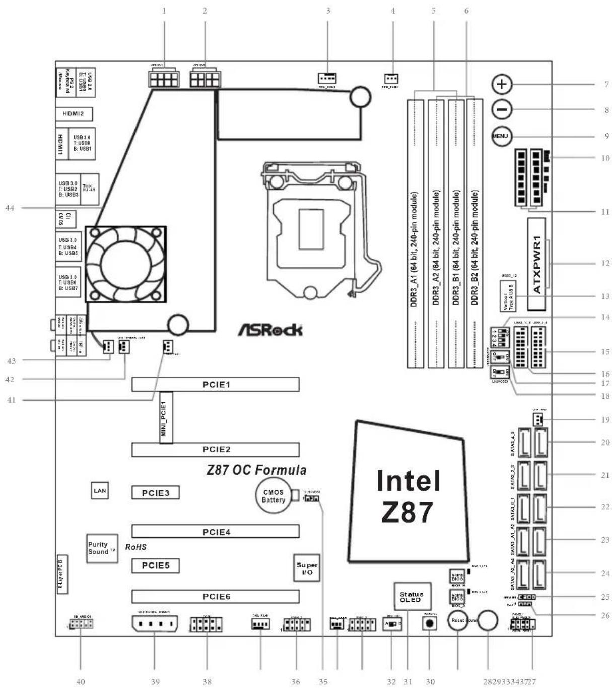
Motherboard Layout
Z87 OC Formula/ac
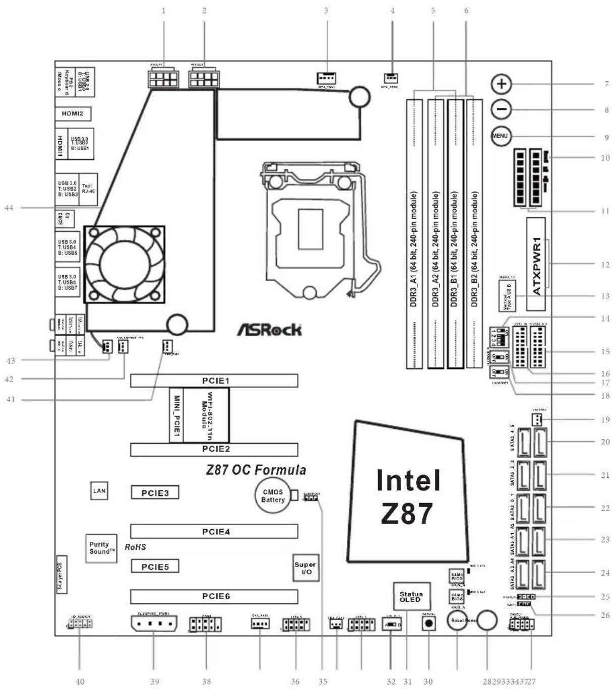
Z87 OC Formula
No.Description
1ATX 12V Power Connector (ATX12V1)
2 ATX 12V Power Connector (ATX12V3)
3 CPU Fan Connector (CPU_FAN1)
4 CPU Fan Connector (CPU_FAN2)
5 2 x 240-pin DDR3 DIMM Slots (DDR3_A1, DDR3_B1)
6 2 x 240-pin DDR3 DIMM Slots (DDR3_A2, DDR3_B2)
7 Rapid OC Button (+)
8 Rapid OC Button (-)
9 Menu Button (MENU1)
10 Post Status Checker (PSC)
11 V-Probe TM (VOL_CON1, VOL_CON2)
12 ATX Power Connector (ATXPWR1)
13 Vertical Type A USB 3.0 (USB3_12)
14 PCIe ON/OFF Switch
15 USB 3.0 Header (USB3_8_9) (ASMedia Hub)
16 USB 3.0 Header (USB3_10_11) (ASMedia Hub)
17 Slow Mode Switch
18 LN2 Mode Switch(LN2MODE1)
19 Chassis Fan Connector (CHA_FAN3)
20 SATA3 Connectors (SATA3_A3_A4)
21 SATA3 Connectors (SATA3_A1_A2)
22 SATA3 Connectors (SATA3_0_1)
23 SATA3 Connectors (SATA3_2_3)
24 SATA3 Connectors (SATA3_4_5)
25 Chassis Speaker Header (SPEAKER1)
26 Power LED Header (PLED1)
27 System Panel Header (PANEL1)
28 Power Switch (PWRBTN1)
29 Reset Switch (RSTBTN1)
30 Clear CMOS Switch
31 Status OLED
32 BIOS Selection Switch (BIOS_SEL1)
33 USB 2.0 Header (USB2_3)
No.Description
34 Chassis Fan Connector (CHA_FAN2)
35 Clear CMOS Jumper (CLRCMOS1)
36 USB 2.0 Header (USB4_5)
37 Chassis Fan Connector (CHA_FAN1)
38 COM Port Header (COM1)
39 SLI/XFIRE Power Connector (SLI/XFIRE_PWR1)
40 Front Panel Audio Header (HD AUDIO1)
41 Power Fan Connector (PWR_FAN1)
42 Chassis Fan Connector (CHA_FAN4)
43 MOS Fan Connector (MOS_FAN1)
44 Twin-Power Cooling
1.5 I/O Panel
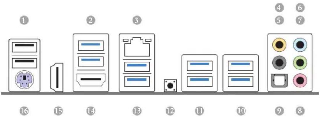
No. Description No. Description
1 USB 2.0 Ports (USB01) 9 Optical SPDIF Out Port
2 USB 3.0 Ports (USB3_01) 10 USB 3.0 Ports (USB3_67)
3 LAN RJ-45 Port 11 USB 3.0 Ports (USB3_45)
4 Central / Bass (Orange) 12 Clear CMOS Switch (CLRCBTN)
5 Rear Speaker (Black) 13 USB 3.0 Ports (USB3_23)
6 Line In (Light Blue) 14 HDMI-Out Port
7 Front Speaker (Lime)**
8 Microphone (Pink)
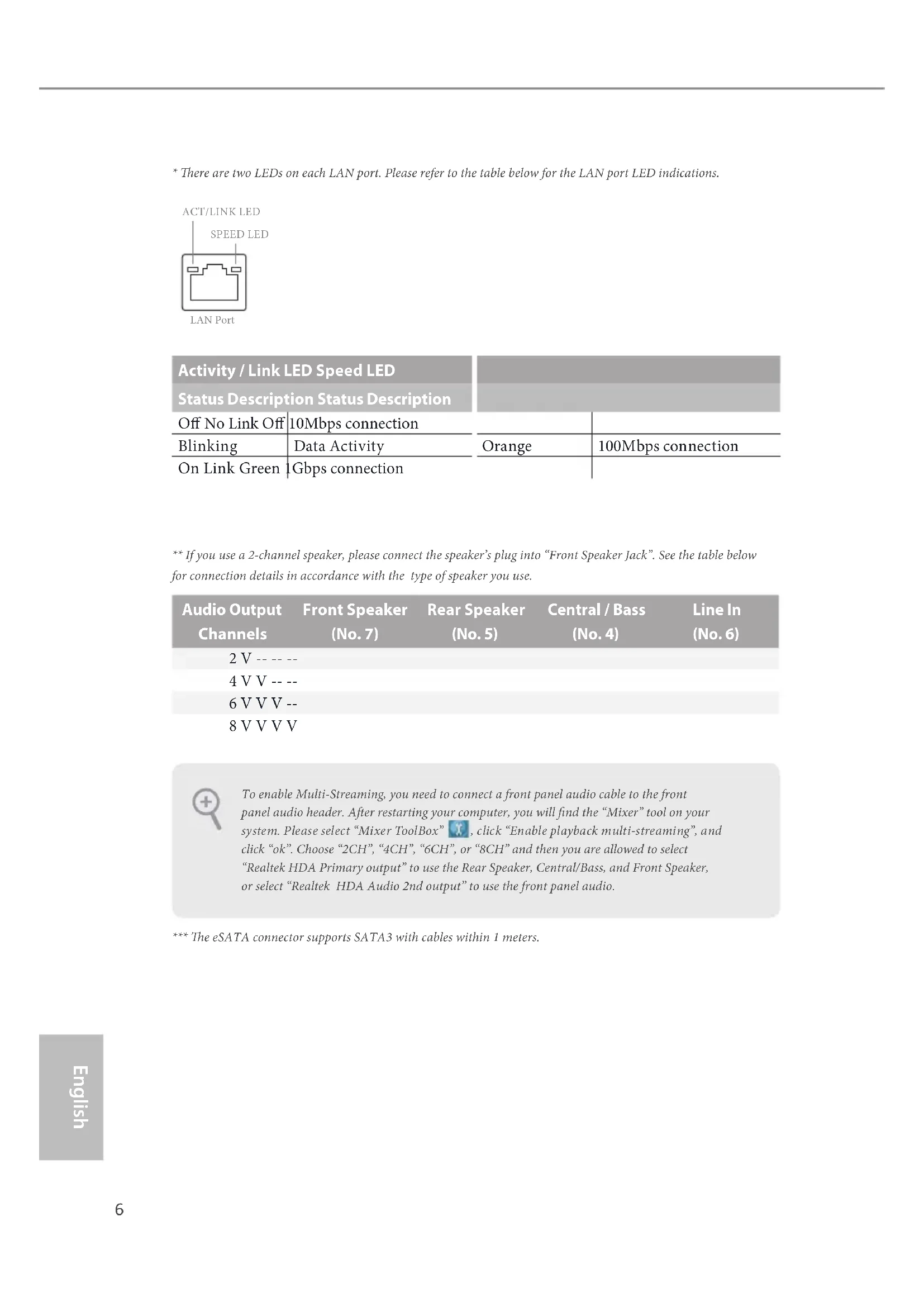
- There are two LEDs on each LAN port. Please refer to the table below for the LAN port LED indications.
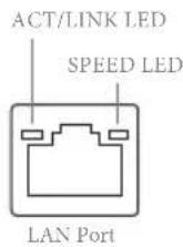
| Activity / Link LED Speed LED | |||
| Status Description Status Description | |||
| Off No Link Off | 10Mbps connection | ||
| Blinking | Data Activity | Orange | 100Mbps connection |
| On Link Green | Gbps connection | ||
** If you use a 2-channel speaker, please connect the speaker's plug into "Front Speaker Jack". See the table below for connection details in accordance with the type of speaker you use.
| Audio Output Channels | Front Speaker (No. 7) | Rear Speaker (No. 5) | Central / Bass (No. 4) | Line In (No. 6) |
| 2 V -- -- -- | ||||
| 4 V V -- -- | ||||
| 6 V V V -- | ||||
| 8 V V V V |

To enable Multi-Streaming, you need to connect a front panel audio cable to the front panel audio header. After restarting your computer, you will find the "Mixer" tool on your system. Please select "Mixer ToolBox", click "Enable playback multi-streaming", and click "ok". Choose "2CH", "4CH", "6CH", or "8CH" and then you are allowed to select "Realtek HDA Primary output" to use the Rear Speaker, Central/Bass, and Front Speaker, or select "Realtek HDA Audio 2nd output" to use the front panel audio.
*** The eSATA connector supports SATA3 with cables within 1 meters.
Chapter 1 Introduction
Thank you for purchasing ASRock Z87 OC Formula/ac / Z87 OC Formula motherboard, a reliable motherboard produced under ASRock's consistently stringent quality control. It delivers excellent performance with robust design conforming to ASRock's commitment to quality and endurance.

Because the motherboard specifications and the BIOS software might be updated, the content of this documentation will be subject to change without notice. In case any modifications of this documentation occur, the updated version will be available on ASRock's website without further notice. If you require technical support related to this motherboard, please visit our website for specific information about the model you are using. You may find the latest VGA cards and CPU support list on ASRock's website as well. ASRock website http://www.asrock.com.
1.1 Package Contents
ASRock Z87 OC Formula/ac / Z87 OC Formula Motherboard (EATX Form Factor)
ASRock Z87 OC Formula/ac / Z87 OC Formula Quick Installation Guide
ASRock Z87 OC Formula/ac / Z87 OC Formula Support CD
10 x Serial ATA (SATA) Data Cables (Optional)
2 x SATA 1 to 1 Power Cables (Optional)
1 x I/O Panel Shield
1 x ASRock Flexible SLI Bridge Connector Cable
1 x Front USB 3.0 Panel with 2.5" HDD/SSD Rack
4 x HDD Screws
6 x Chassis Screws
1 x Rear USB 3.0 Bracket
10 x OC Stands
GELID Solutions GC-Extreme Thermal Compound
1 x ASRock WiFi 2.4/5GHz Antenna (for Z87 OC Formula/ac only)
2 x SMA Wi-Fi Antenna Cables (for Z87 OC Formula/ac only)
1 x WiFi Module Screw (for Z87 OC Formula only)
1.2 Specifications
| Platform | EATX Form Factor (12.0-in x 10.5-in, 30.5 cm x 26.7 cm) Premium Gold Capacitor design (100% Japan-made high-quality Conductive Polymer Capacitors) |
| A-Style | Home Cloud Conformal Coating Purity SoundTM 802.11ac WiFi (for Z87 OC Formula/ac only) HDMI-In |
| OC Formula Kit | OC Formula Power Kit 12 Power Phase Design Digi Power Dual-Stack MOSFET (DSM) Multiple Filter Cap (MFC) (Filter different noise by 3 different capacitors: DIP solid cap, POSCAP and MLCC) Premium Alloy Choke (Reduce 70% core loss compare to iron powder choke) OC Formula Connector Kit Hi-Density Power Connector (8 pin) 15μGold Finger (CPU sockets, memory sockets and PCIE x16 slots) Distortion-Free Slot OC Formula Cooling Kit Twin-Power Cooling (Combine active air cooling and water cooling) 8 Layer PCB 4 x 2oz copper Gelid Solution GC-Extreme Thermal Compound OC Formula Monitor Kit Status OLED Multi Thermal Sensor |
| CPU | Supports 4th Generation Intel® CoreTM i7 / i5 / i3 / Xeon® / Pentium® / Celeron® in LGA1150 Package 12 Power Phase Design Supports Intel® Turbo Boost 2.0 Technology Supports Intel® K-Series unlocked CPU Supports ASRock BCLK Full-range Overclocking |
| Chipset | Intel®Z87 |
| Memory | Dual Channel DDR3 memory technology 4 x DDR3 DIMM slots Supports DDR3 3000+(OC)/2933(OC)/2800(OC)/2400(OC) /2133(OC)/1866(OC)/1600/1333/1066 non-ECC, un-buffered memory Max. capacity of system memory: 32GB Supports Intel®Extreme Memory Profile (XMP) 1.3 / 1.2 Distortion-Free Slot |
| Expansion Slot | 3 x PCI Express 3.0 x16 slots (PCIE1/PCIE2/PCIE4: single at x16 (PCIE1); dual at x8 (PCIE1) / x8 (PCIE4); triple at x8 (PCIE1) / x4 (PCIE2) / x4 (PCIE4)) 1 x PCI Express 2.0 x16 slot (PCIE6: x4 mode) 2 x PCI Express 2.0 x1 slots 1 x mini-PCI Express slot: For WiFi + BT module *mini-PCI Express slot is shared with PCIE5 slot PLX8605 embedded Supports AMD Quad CrossFireX™, 4-Way CrossFireX™, 3-Way CrossFireX™ and CrossFireX™ Supports NVIDIA®Quad SLI™ and SLITM |
| Graphics | Intel®HD Graphics Built-in Visuals and the VGA outputs can be supported only with processors which are GPU integrated. Supports Intel®HD Graphics Built-in Visuals : Intel®Quick Sync Video with AVC, MVC (S3D) and MPEG-2 Full HW Encode1, Intel®InTru™3D, Intel®Clear Video HD Technology, Intel®Insider™, Intel®HD Graphics 4400/4600 Pixel Shader 5.0, DirectX 11.1 Max. shared memory 1792MB Supports HDMI Technology with max. resolution up to 4K × 2K (4096x2304) @ 24Hz Supports Auto Lip Sync, Deep Color (12bpc), xvYCC and HBR (High Bit Rate Audio) with HDMI (Compliant HDMI monitor is required) Supports HDCP function with HDMI port Supports Full HD 1080p Blu-ray (BD) playback with HDMI port |
Audio
7.1 CH HD Audio with Content Protection (Realtek ALC1150
Audio Codec)
Premium Blu-ray audio support
Supports Purity Sound
- 115dB SNR DAC with differential amplifier
- TI® NE5532 Premium Headset Amplifier (supports up to 600 Ohms headsets)
- Direct Drive Technology
- EMI shielding cover
PCB isolate shielding
Supports DTS Connect
LAN
Gigabit LAN 10/100/1000 Mb/s
Giga PHY Intel® I217V
Supports Intell® Remote Wake Technology
Supports Wake-On-LAN
Supports Energy Efficient Ethernet 802.3az
Supports PXE
Rear Panel
1 x PS/2 Mouse/Keyboard Port
I/O
1 x HDMI-Out Port
1 x HDMI-In Port
1 x Optical SPDIF Out Port
2xUSB2.0Ports
4x USB 3.0 Ports (Intel Z87)
- USB3_10_11 is shared with PCIE6. If the PCIE6 slot is
occupied, USB3_10_11 shifts to USB 2.0.
4xUSB3.0Ports (EtronEJ188H)
1 x RJ-45 LAN Port with LED (ACT/LINK LED and SPEED)
LED)
1xClearCMOSButton
HD Audio Jack: Rear Speaker / Central / Bass / Line in / Front
Speaker / Microphone
Storage
6 x SATA3 6.0 Gb/s connectors by Intel® Z87, support RAID (RAID 0, RAID 1, RAID 5, RAID 10, Intel Rapid Storage Technology 12 and Intel Smart Response Technology), NCQ, AHCI and Hot Plug
4 x SATA3 6.0 Gb/s connectors by ASMia ASM1061, support NCQ, AHCI and Hot Plug
Connector
1xCOMportheader
1xPowerLEDheader
2 x CPU Fan connectors (1 x 4-pin, 1 x 3-pin)
4 x Chassis Fan connectors (1 x 4-pin, 3 x 3-pin)
1 x Power Fan connector (3-pin)
1 x MOS Fan connector (3-pin)
1 x 24 pin ATX power connector
2 × 8 pin 12V power connectors (Hi-Density Power Connector)
1 x SLI/XFire power connector
1 x Front panel audio connector
2xUSB2.0 headers (support6USB2.0ports)
1 x Vertical Type A USB 3.0
2 x USB 3.0 headers (support 4 USB 3.0 ports) (ASMedia Hub)
1 x Power Switch with LED
1 x Reset Switch with LED
1 x Clear CMOS Switch
V-ProbeTM: 2 x 7-set of onboard voltage measurement points laid
Rapid OC Button: + / - buttons to adjust OC frequency
1 x PCIe ON/OFF Switch
1 x Post Status Checker (PSC)
1 x Slow Mode Switch
1 x LN2 Mode Switch
1 x BIOS Selection Switch
BIOS
Feature
2 x 64Mb AMI UEFI Legal BIOS with Multilingual GUI support (1 x Main BIOS and 1 x Backup BIOS)
Supports Secure Backup UEFI Technology
ACPI 1.1 Compliance Wake Up Events
SMBIOS 2.3.1 Support
CPU, DRAM, PCH 1.05V, PCH 1.5V Voltage Multi-adjustment
| Support CD | Drivers, Utilities, AntiVirus Software (Trial Version), Cyber-Link MediaEspresso 6.5 Trial, Google Chrome Browser and Toolbar, Start8, MeshCentral, Splashtop Streamer |
| Hardware | CPU/Chassis/Power/MOS Temperature SensingCPU/Chassis/Power/MOS Fan TachometerCPU/Chassis/MOS Quiet Fan (Allows Chassis Fan Speed Auto-Adjust by CPU Temperature)CPU/Chassis/MOS Fan Multi-Speed ControlMulti Thermal SensorVoltage Monitoring: +12V, +5V, +3.3V, CPU Vcore1 x Status OLED |
| OS | Microsoft® Windows® 8 / 8 64-bit / 7 / 7 64-bit compliant |
| Certifications | FCC, CE, WHQLErP/EuP Ready (ErP/EuP ready power supply is required) |
- For detailed product information, please visit our website: http://www.asrock.com
| Please realize that there is a certain risk involved with overclocking, including adjusting the setting in the BIOS, applying Untied Overclocking Technology, or using third-party overclocking tools. Overclocking may affect your system's stability, or even cause damage to the components and devices of your system. It should be done at your own risk and expense. We are not responsible for possible damage caused by overclocking. |
| Due to limitation, the actual memory size may be less than 4GB for the reservation for system usage under Windows® 32-bit operating systems. Windows® 64-bit operating systems do not have such limitations. You can use ASRock XFast RAM to utilize the memory that Windows® cannot use. |
1.3 Unique Features

ASRock Formula Drive
Formula Drive is ASRock's multi purpose software suite with a new interface, more new features and improved utilities, including XFast RAM, Dehumidifier, Good Night LED, FAN-Tastic Tuning, OC Tweaker and a whole lot more.

ASRock Instant Flash
ASRock Instant Flash is a BIOS flash utility embedded in Flash ROM. This convenient BIOS update tool allows you to update the system BIOS in a few clicks without preparing an additional floppy diskette or other complicated flash utility. Just save the new BIOS file to your USB storage and launch this tool by pressing <F6> or <F2> during POST to enter the BIOS setup menu to access ASRock Instant Flash. Please be noted that the USB flash drive or hard drive must use FAT32/16/12 file system.

ASRock APP Charger
Simply by installing the ASRock APP Charger makes your iPhone/iPad/iPod Touch charge up to 40% faster than before on your computer. ASRock APP Charger allows you to quickly charge many Apple devices simultaneously and even supports continuous charging when your PC enters into Standby mode (S1), Suspend to RAM (S3), hibernation mode (S4) or power off (S5).

ASRock XFast USB
ASRock XFast USB can boost the performance of your USB storage devices. The performance may depend on the properties of the device.

ASRock XFast LAN
ASRock XFast LAN provides faster internet access, which includes the benefits listed below. LAN Application Prioritization: You can configure your application's priority ideally and add new programs to the list. Lower Latency in Game: After setting online game's priority higher, it can lower the latency in games. Traffic Shaping: You can watch Youtube HD videos and download simultaneously. Real-Time Analysis of Your Data: With the status window, you can easily recognize which data streams you are currently transferring.

ASRock XFast RAM
ASRock XFast RAM is included in A-Tuning. It fully utilizes the memory space that cannot be used under Windows® 32-bit operating systems. ASRock XFast RAM shortens the loading time of previously visited websites, making web surfing faster than ever. And it also boosts the speed of Adobe Photoshop 5 times faster. Another advantage of ASRock XFast RAM is that it reduces the frequency of accessing your SSDs or HDDs in order to extend their lifespan.

ASRock Crashless BIOS
ASRock Crashless BIOS allows users to update their BIOS without fear of failing. If power loss occurs during the BIOS updating process, ASRock Crashless BIOS will automatically finish the BIOS update procedure after regaining power. Please note that BIOS files need to be placed in the root directory of your USB disk. Only USB 2.0 ports support this feature.

ASRock OMG (Online Management Guard)
Administrators are able to establish an internet curfew or restrict internet access at specified times via OMG. You may schedule the starting and ending hours of internet access granted to other users. In order to prevent users from bypassing OMG, guest accounts without permission to modify the system time are required.

ASRock Internet Flash
ASRock Internet Flash downloads and updates the latest UEFI firmware version from our servers for you without entering Windows OS. Please setup network configuration before using Internet Flash.

ASRock UEFI System Browser
ASRock System Browser shows the overview of your current PC and the devices connected.

ASRock Dehumidifier Function
Users may prevent motherboard damages due to dampness by enabling "Dehumidifier Function". When enabling Dehumidifier Function, the computer will power on automatically to dehumidify the system after entering S4/S5 state.

ASRock Easy RAID Installer
ASRock Easy RAID Installer can help you to copy the RAID driver from the support CD to your USB storage device. After copying the RAID driver to your USB storage device, please change "SATA Mode" to "RAID", then you can start installing the OS in RAID mode.

ASRock Easy Driver Installer
For users that don't have an optical disk drive to install the drivers from our support CD, Easy Driver Installer is a handy tool in the UEFI that installs the LAN driver to your system via an USB storage device, then downloads and installs the other required drivers automatically.

ASRock Interactive UEFI
ASRock Interactive UEFI is a blend of system configuration tools, cool sound effects and stunning visuals. The unprecedented UEFI provides a more attractive interface and more amusement.

ASRock Fast Boot
With ASRock's exclusive Fast Boot technology, it takes less than 1.5 seconds to logon to Windows 8 from a cold boot. No more waiting! The speedy boot will completely change your user experience and behavior.

ASRock Restart to UEFI
Windows® 8 brings the ultimate boot up experience. The lightning boot up speed makes it hard to access the UEFI setup. ASRock Restart to UEFI allows users to enter the UEFI automatically when turning on the PC. By enabling this function, the PC will enter the UEFI directly after you restart.
NickShih's OC Profile
Have you ever wondered how the global OC champion overclocks his motherboards? Now you've got a chance to learn a few tricks from the champion with NickShih's OC Profile. It doesn't matter whether you're using a K-Series or No-K Series CPU, NickShih's OC Profile will automatically detect your CPU and offer you different levels of overclocking. Have a taste of Nick's secret recipe for overclocking this motherboard instantly.
Fine-Tuning V-Controller
Fine-Tuning V-Controller is a new collection of voltage fine tuning options in ASRock UEFI Setup Utility. It provides more than enough voltage configuration options for overclockers who wish to pursuit extremes.
Timing Configurator
Timing Configurator is a fast and easy tool that provides users with an abundant collection of subtle DRAM settings for professional tweaking. You won't even have to waste time on entering into the UEFI or restarting the system, Timing Configurator is an independent application that runs under Windows OS and your changes will take effect immediately.

ASRock Good Night LED
ASRock Good Night LED technology offers you a better sleeping environment by extinguishing the unessential LEDs. By enabling Good Night LED in the BIOS, the Power/HDD LEDs will be switched off when the system is powered on. Good night LED will automatically switch off the Power and Keyboard LEDs when the system enters into Standby/Hibernation mode as well.

ASRock USB Key
In a world where time is money, why waste precious time everyday typing usernames to log in to Windows? Why should we even bother memorizing those foot long passwords? Just plug in the USB Key and let your computer log in to windows automatically!

ASRock Conformal Coating
Conductive liquids such as water pretty much destroy all kinds of electronics on contact. That's why ASRock has implemented a special layer of Conformal Coating on our motherboards, which makes the motherboards invulnerable to conductive liquids, corrosion and dust. Users won't have to worry about spilling liquid nitrogen, liquid helium or even clam chowder over their motherboards while overclocking.
*Conformal Coating may protect the motherboard against conductive liquids, but only to a certain extent. To avoid damaging your computer and other components, we still advise users to keep liquids a safe distance away.

ASRock Home Cloud
This motherboard supports remote wake with the onboard Intel LAN, so you can connect with your PC from anywhere in the world. You will be able to power your PC on or turn it off, monitor and take control of it remotely with another smartphone, tablet or computer.

Status OLED
Status OLED shows various information of the system on a new high resolution OLED screen. Now you can use three buttons to toggle between information of the power on self test, debug codes, the current time, temperatures, frequencies and voltages of various points on the motherboard.

ASRock FAN-Tastic Tuning
ASRock FAN-Tastic Tuning is included in Formula Drive. Configure up to five different fan speeds using the graph. The fans will automatically shift to the next speed level when the assigned temperature is met.
ASRock Distortion-Free Slot
ASRock's new pin design for the memory slots may appear to be the same as former designs, but actually effectively reduces distortion and promotes performance, because we strive for perfection even in the most trivial details.
1.4 WiFi-802.11n Module and ASRock WiFi 2.4GHz Antenna (for Z87 OC Formula/ac only)
WiFi + BT Module
This motherboard comes with an exclusive WiFi 802.11 a/b/g/n/ac + BT v4.0 module that offers support for WiFi 802.11 a/b/g/n/ac connectivity standards and Bluetooth v4.0. WiFi + BT module is an easy-to-use wireless local area network (WLAN) adapter to support WiFi + BT. Bluetooth v4.0 standard features Smart Ready technology that adds a whole new class of functionality into the mobile devices including Apple's most recent iPhone 4S. BT 4.0 also includes Low Energy Technology and ensures extraordinary low power consumption for PCs. The 2T2R WiFi solution sets a WiFi high speed standard and offers max link rate up to 867Mbps.
- The transmission speed may vary according to the environment.
- The WiFi + BT module is supported under Windows* 8 / 8 64-bit / 7 / 7 64-bit only.

ASRock WiFi 2.4GHz Antenna
Installing the SMA Wi-Fi Antenna Cables
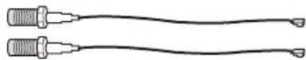
Step 1
Prepare the SMA Wi-Fi Antenna Cables that come with the package.
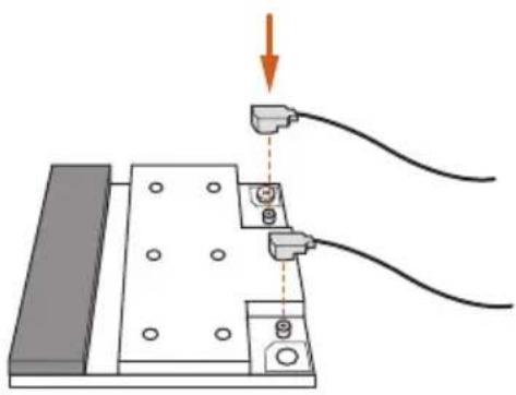
Step 2
Locate the WiFi Module that is installed on the motherboard's mini-PCIe slot. Then attach the SMA Wi-Fi Antenna Cables to the WiFi Module.
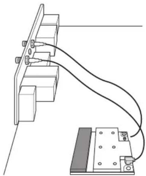
Step3
Insert the RP-SMA Wi-Fi Antenna Connectors to the antenna ports on the I/O shield
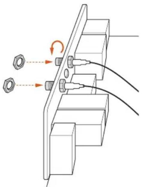
Step 4
Fasten the screw nuts to secure the connectors.
Chapter 2 Installation
This is an EATX form factor motherboard. Before you install the motherboard, study the configuration of your chassis to ensure that the motherboard fits into it.
Pre-installation Precautions
Take note of the following precautions before you install motherboard components or change any motherboard settings.
Make sure to unplug the power cord before installing or removing the motherboard.
Failure to do so may cause physical injuries to you and damages to motherboard components.
In order to avoid damage from static electricity to the motherboard's components, NEVER place your motherboard directly on a carpet. Also remember to use a grounded wrist strap or touch a safety grounded object before you handle the components.
Hold components by the edges and do not touch the ICs.
Whenever you uninstall any components, place them on a grounded anti-static pad or in the bag that comes with the components.
When placing screws to secure the motherboard to the chassis, please do not overtighten the screws! Doing so may damage the motherboard.
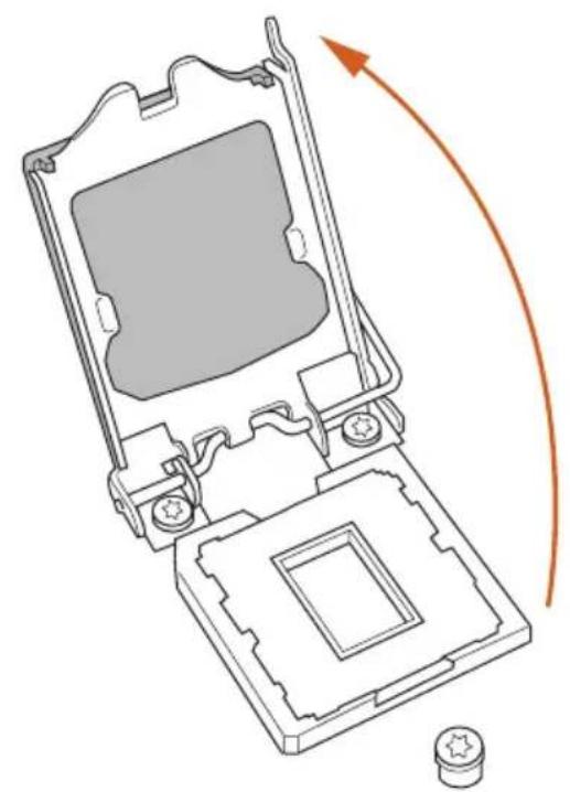
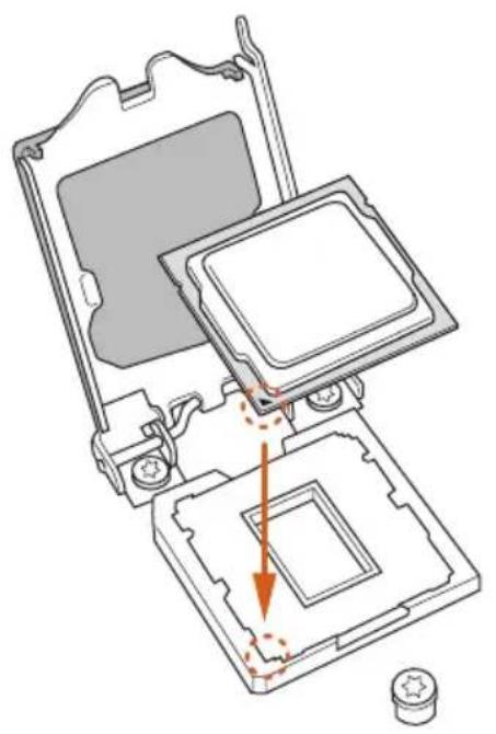
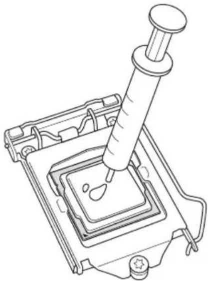
2.1 Installing the CPU

- Before you insert the 1150-Pin CPU into the socket, please check if the PnP cap is on the socket, if the CPU surface is unclean, or if there are any bent pins in the socket. Do not force to insert the CPU into the socket if above situation is found. Otherwise, the CPU will be seriously damaged.
- Unplug all power cables before installing the CPU.
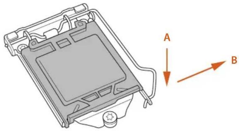
1
2
3
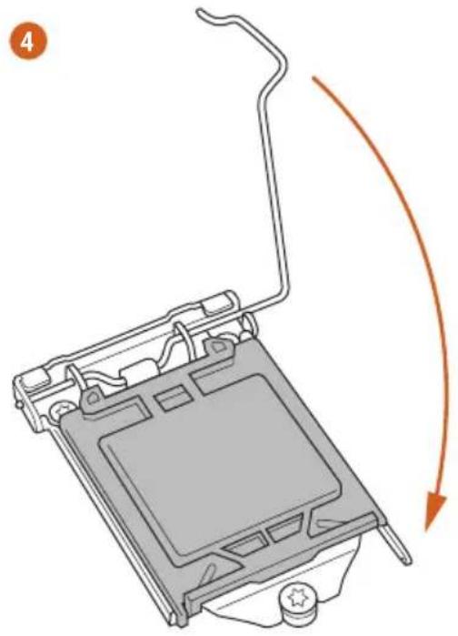
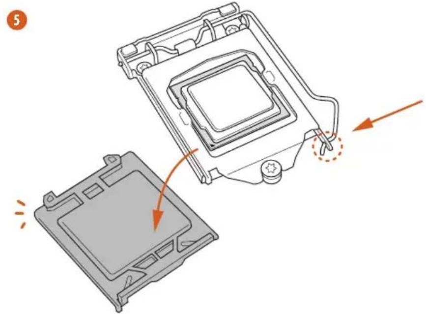

Please save and replace the cover if the processor is removed. The cover must be placed if you wish to return the motherboard for after service.
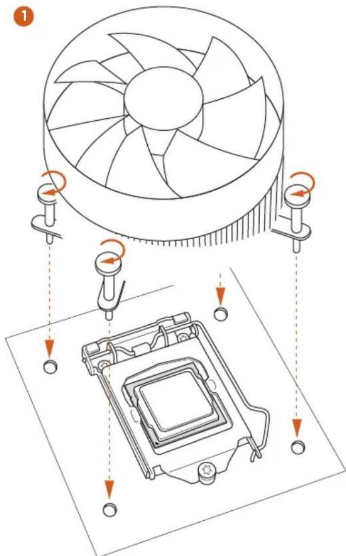
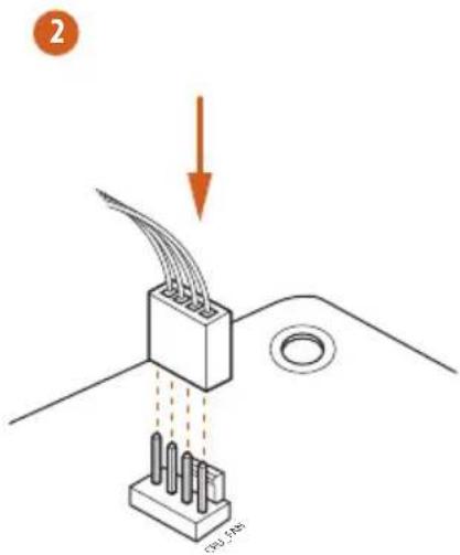
2.2 Installing the CPU Fan and Heatsink
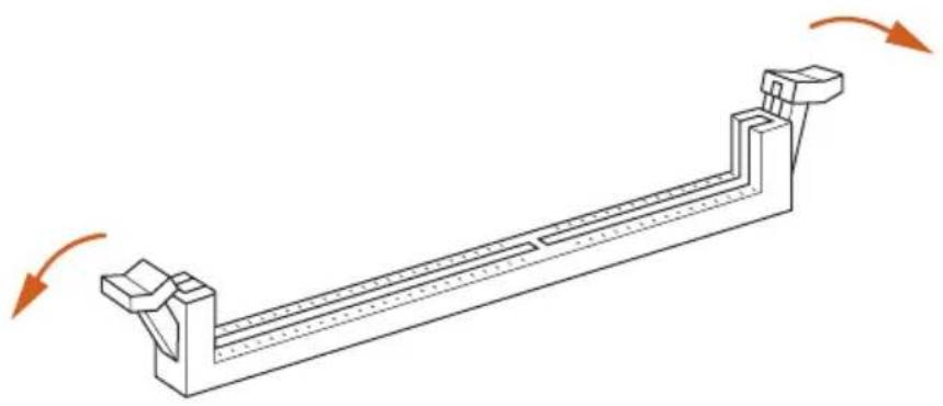
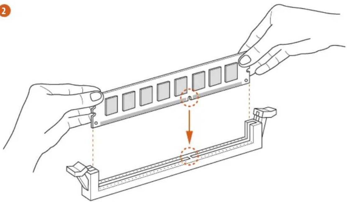
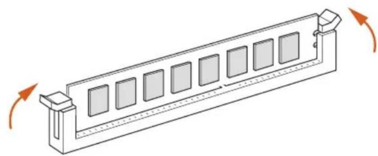
2.3 Installing Memory Modules (DIMM)
This motherboard provides four 240-pin DDR3 (Double Data Rate 3) DIMM slots, and supports Dual Channel Memory Technology.

- For dual channel configuration, you always need to install identical (the same brand, speed, size and chip-type) DDR3 DIMM pairs.
- It is unable to activate Dual Channel Memory Technology with only one or three memory module installed.
- It is not allowed to install a DDR or DDR2 memory module into a DDR3 slot; otherwise, this motherboard and DIMM may be damaged.
Dual Channel Memory Configuration
| Priority DDR3_A1 DDR3_A2 DDR3_B1 DDR3_B2 | |||
| 1 Populated | Populated | ||
| 2 Populated | Populated | ||
| 3 Populated | Populated | Populated | Populated |

The DIMM only fits in one correct orientation. It will cause permanent damage to the motherboard and the DIMM if you force the DIMM into the slot at incorrect orientation.
1
2
3
2.4 Expansion Slots (PCI and PCI Express Slots)
There are 6 PCI Express slots and 1 mini-PCI Express slot on the motherboard.

Before installing an expansion card, please make sure that the power supply is switched off or the power cord is unplugged. Please read the documentation of the expansion card and make necessary hardware settings for the card before you start the installation.
PCIE slots:
PCIE1 (PCIE 3.0 x16 slot) is used for PCI Express x16 lane width graphics cards.
PCIE2 (PCIE 3.0 x16 slot) is used for PCI Express x4 lane width graphics cards.
PCIE3 (PCIE 2.0 x1 slot) is used for PCI Express x1 lane width cards.
PCIE4 (PCIE 3.0 x16 slot) is used for PCI Express x8 lane width graphics cards.
PCIE5 (PCIE 2.0 x1 slot) is used for PCI Express x1 lane width cards.
PCIE6 (PCIE 2.0 x16 slot) is used for PCI Express x4 lane width graphics cards.
mini-PCIe slots:
MINI_PCIE1 (mini-PCie slot) is used for WiFi module.
PCIE Slot Configurations
Single Graphics Card x16 N/AN/AN/A
Two Graphics Cards in CrossFireXTM or SLITM Mode
x8 N/A x8 N/A
Three Graphics Cards in 3-Way CrossFireXTM Mode
x8 x4 x4 N/A
Four Graphics Cards in 4-Way CrossFireXTM Mode
x8 x4 x4 x4

For a better thermal environment, please connect a chassis fan to the motherboard's chassis fan connector (CHA_FAN1, CHA_FAN2, CHA_FAN3 or CHA_FAN4) when using multiple graphics cards.
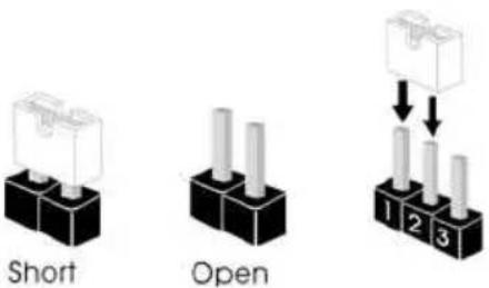
2.5 Jumpers Setup
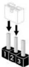
The illustration shows how jumpers are setup. When the jumper cap is placed on the pins, the jumper is "Short". If no jumper cap is placed on the pins, the jumper is "Open". The illustration shows a 3-pin jumper whose pin1 and pin2 are "Short" when a jumper cap is placed on these 2 pins.
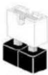
Short
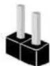
Open
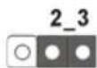
Clear CMOS Jumper (CLRCMOS1)
(see p.1 or 2, No. 35)
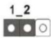
Clear CMOSDefault
CLRCMOS1 allows you to clear the data in CMOS. To clear and reset the system parameters to default setup, please turn off the computer and unplug the power cord from the power supply. After waiting for 15 seconds, use a jumper cap to short pin2 and pin3 on CLRCMOS1 for 5 seconds. However, please do not clear the CMOS right after you update the BIOS. If you need to clear the CMOS when you just finish updating the BIOS, you must boot up the system first, and then shut it down before you do the clear-CMOS action. Please be noted that the password, date, time, and user default profile will be cleared only if the CMOS battery is removed.

The Clear CMOS Switch has the same function as the Clear CMOS jumper.
2.6 Onboard Headers and Connectors

Onboard headers and connectors are NOT jumpers. Do NOT place jumper caps over these headers and connectors. Placing jumper caps over the headers and connectors will cause permanent damage to the motherboard.
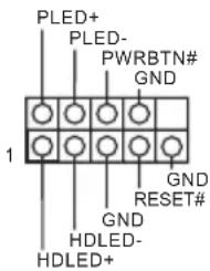
System Panel Header (9-pin PANEL1) (see p.1 or 2, No. 27)
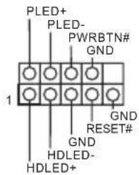
Connect the power switch, reset switch and system status indicator on the chassis to this header according to the pin assignments below. Note the positive and negative pins before connecting the cables.

PWRBTN (Power Switch):
Connect to the power switch on the chassis front panel. You may configure the way to turn off your system using the power switch.
RESET (Reset Switch):
Connect to the reset switch on the chassis front panel. Press the reset switch to restart the computer if the computer freezes and fails to perform a normal restart.
PLED (System Power LED):
Connect to the power status indicator on the chassis front panel. The LED is on when the system is operating. The LED keeps blinking when the system is in S1/S3 sleep state. The LED is off when the system is in S4 sleep state or powered off (S5).
HDLED (Hard Drive Activity LED):
Connect to the hard drive activity LED on the chassis front panel. The LED is on when the hard drive is reading or writing data.
The front panel design may differ by chassis. A front panel module mainly consists of power switch, reset switch, power LED, hard drive activity LED, speaker and etc. When connecting your chassis front panel module to this header, make sure the wire assignments and the pin assignments are matched correctly.
| Power LED Header (3-pin PLED1) (see p.12, No. 17) | PLED-PLED+ | Please connect the chassis power LED to this header to indicate the system's power status. |
| Serial ATA3 Connectors (SATA3_0_1: see p.1 or 2, No. 22) (SATA1_2_3: see p.1 or 2, No. 23) (SATA3_4_5: see p.1 or 2, No. 24) (SATA3_A1_A2: see p.1 or 2, No. 21) (SATA3_A3_A4: see p.1 or 2, No. 20) | SATA3_4_5_SATA3_4_5 | These ten SATA3 connectors support SATA data cables for internal storage devices with up to 6.0 Gb/s data transfer rate. To minimize the boot time, use Intel® Z87 SATA ports (SATA3_0) for your bootable devices. |
| SATA3_0_1_SATA3_4_4_SATA3_A1_A2 | SATA3_0_1_SATA3_4_4_SATA3_A1_A2 | |
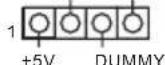
| USB 2.0 Headers (9-pin USB2_3) (see p.1 or 2, No. 33) (9-pin USB4_5) (see p.1 or 2, No. 36) | USB_PWR P- P+ GND DUMMY P- P+ GND USB_PWR | Besides two USB 2.0 ports on the I/O panel, there are two headers on this motherboard. Each USB 2.0 header can support two ports. |
USB 3.0 Headers
(19-pin USB3_8_9)
(see p.1 or 2, No. 15)
(19-pin USB3_10_11)
(see p.1 or 2, No. 16)
(USB3_12)
(see p.1 or 2, No. 13)
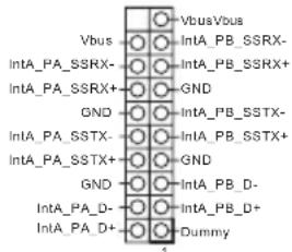

Besides four USB 3.0 ports on the I/O panel, there are two headers and one port on this motherboard. Each USB 3.0 header can support two ports.
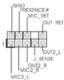
Front Panel Audio Header
(9-pin HD_AUDIO1)
(see p.1 or 2, No. 40)
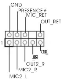
This header is for connecting audio devices to the front audio panel.

- High Definition Audio supports Jack Sensing, but the panel wire on the chassis must support HDA to function correctly. Please follow the instructions in our manual and chassis manual to install your system.
- If you use an AC'97 audio panel, please install it to the front panel audio header by the steps below:
A. Connect Mic_IN (MIC) to MIC2_L.
B. Connect Audio_R (RIN) to OUT2_R and Audio_L (LIN) to OUT2_L.
C. Connect Ground (GND) to Ground (GND).
D. MIC_RET and OUT_RET are for the HD audio panel only. You don't need to connect them for the AC'97 audio panel.
E. To activate the front mic, go to the "FrontMic" Tab in the Realtek Control panel and adjust "Recording Volume".
Chassis Speaker Header (4-pin SPEAKER1)
(see p.1 or 2, No. 25)
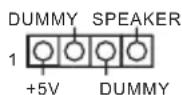
Please connect the chassis speaker to this header.
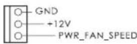
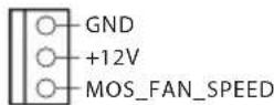
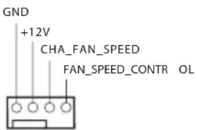
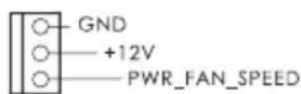
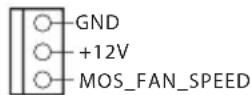
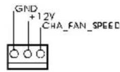
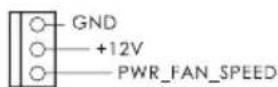
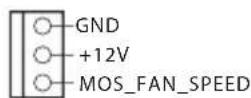
Chassis, Power and MOS Fan Connectors (4-pin CHA_FAN1) (see p.1 or 2, No.37)
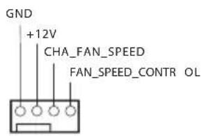
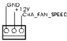
Please connect fan cables to the fan connectors and match the black wire to the ground pin.
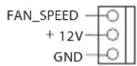
(3-pin CHA_FAN2) (see p.1 or 2, No. 34)
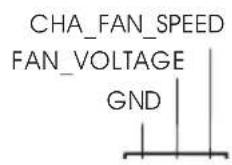
(3-pin CHA_FAN3) (see p.1 or 2, No. 19)
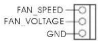
(3-pin CHA_FAN4) (see p.1 or 2, No. 42)
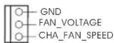
(3-pin PWR_FAN1) (see p.1 or 2, No.41)
(3-pin MOS_FAN1) (see p.1 or 2, No.43)
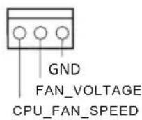
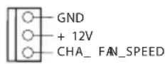
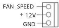
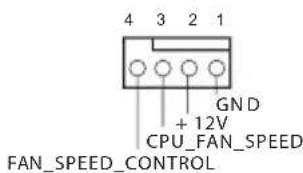
CPU Fan Connectors (4-pin CPU_FAN1) (see p.1 or 2, No.3)
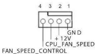
This motherboard provides a 4-Pin CPU fan (Quiet Fan) connector. If you plan to connect a 3-Pin CPU fan, please connect it to Pin 1-3.
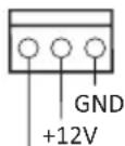
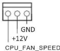
(3-pin CPU_FAN2) (see p.1 or 2, No.4)
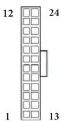
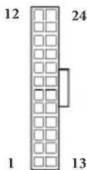
ATX Power Connector (24-pin ATXPWR1) (see p.1 or 2, No. 12)
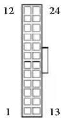
This motherboard provides a 24-pin ATX power connector. To use a 20-pin ATX power supply, please plug it along Pin 1 and Pin 13.
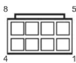
| ATX 12V Power Connector (8-pin ATX12V1) (see p.1 or 2, No. 1) (8-pin ATX12V3) (see p.1 or 2, No. 2) | 8 5 4 1 | This motherboard pro- vides an 8-pin ATX 12V power connector. To use a 4-pin ATX power supply, please plug it along Pin 1 and Pin 5. |
| SLI/XFIRE Power Connector (4-pin SLI/XFIRE_ PWR1) (see p.1 or 2, No. 39) | Please connect this connector with a hard disk power connector when two graphics cards are installed on this motherboard. | |
| Serial Port Header (9-pin COM1) (see p.1 or 2, No. 38) | RRXD1 DDRTR#1 DDRSR#1 CCTS#1 GND TTXD1 DCCD#1 | This COM1 header supports a serial port module. |
V-ProbeTM
(7-pin VOL
CON1,7-pin VOL_
CON2)
(see p.1 or 2, No.
11)
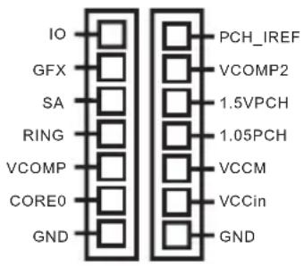
Users are able to measure onboard components voltage.
PCH_IREF:
PCH1.5V IREF voltage
VCOMP2:
CPU 2nd COMP voltage
1.5VPCH:
PCH 1.5V voltage
1.05PCH:
PCH 1.05V voltage
VCCM:
DRAM voltage
VCC-in:
CPU input voltage
10:
CPU IO voltage
GFX:
CPU GFX (Graphics)
voltage
SA:
CPU system agent voltage
RING:
CPU Ring (cache) voltage
VCOMP:
CPU COMP voltage
CORE0:
CPU CORE0 voltage
2.7 Smart Switches
The motherboard has three smart switches: Power Switch, Reset Switch and Clear CMOS Switch, allowing users to quickly turn on/off the system, reset the system or clear the CMOS values.
| Power Switch (PWRBTN) (see p.1 or 2, No. 28) | Power | Power Switch allows users to quickly turn on/off the system. |
| Reset Switch (RSTBTN) (see p.1 or 2, No. 29) | Reset | Reset Switch allows users to quickly reset the system. |
| Clear CMOS Switch (CLRCBTN) (see p.1 or 2, No. 30) | Clear CMOS Switch allows users to quickly clear the CMOS values. | |
| This function is workable only when you power off your computer and unplug the power supply. | ||
| + / - Rapid OC Buttons (MINUS1: see p.1 or 2, No. 7) (PLUS1: see p.1 or 2, No. 8) | + / - Rapid OC Buttons allow users to quickly and easily adjust OC frequency in Rapid OC. | |
| This overclocking behavior depends on the system configuration, such as memory capabil- ity, thermal solution, etc. Overclocking may affect your system stability, or even cause dam- age to the components and devices. We are not responsible for possible damage caused by overclocking. | ||
| Menu Button (MENU1: see p.1 or 2, No. 9) | MENU | MENU Button allow users to quickly toggle among Date/ Time, Temperature, and Volt- age information shown on Status OLED. |
PCIe ON/OFF
Switch
(SWITCH1)
(see p.1 or 2 No. 14)
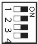
1:PCIE1
2:PCIE2
3:PCIE4
4:PCIE6
PCIe ON/OFF Switch allows you to enable and disable the corresponding PCIE x16 slots. When one of the installed PCIE x16 cards is out of order, you can use PCIe ON/OFF Switch to find out the faulty one just with a single click without removing the cards.

- Make sure that you power off the system before changing the switch.
- When you turn off PCIe ON/OFF switch, your PCIE card could be burnt if it was poorly designed. For more information about your card's specifications please contact the card's vendor.
- PCIe ON/OFF switch is for debug only. If you do not want to use your PCIe card, please remove it from the motherboard.
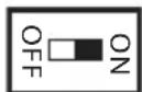
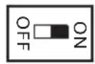
Slow Mode Switch
(SLOWMODE1)
(see p.1 or 2 No. 17)
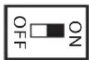
If Slow Mode is on, the processor runs at lowest frequency.
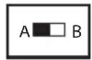
BIOS Selection
Switch
(BIOS_SEL1)
(see p.1 or 2 No.32)
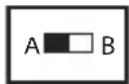
BIOS Selection Switch allows the system to boot from either BIOS A or BIOS B.

This motherboard has two BIOS chips, a primary BIOS (BIOS_A) and a backup BIOS (BIOS_B), which enhances the safety and stability of your system. Normally, the system will work on the primary BIOS. However, if the primary BIOS is corrupted or damaged, just flip the BIOS Selection Switch to "B", then the backup BIOS will take over on the next system boot. After that, use "Secure Backup UEFI" in the UEFI Setup Utility to duplicate a working copy of the BIOS files to the primary BIOS to ensure normal system operation. For safety issues, users are not able to update the backup BIOS manually. Users may refer to the BIOS LEDs (BIOS_A_LED or BIOS_B_LED) to identify which BIOS is currently activated.
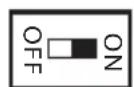
LN2 Mode Switch
(LN2MODE1)
(see p.1 or 2, No. 18)
The LN2 mode aids in eliminating the cold-boot bug issues in processors during extreme overclocking with Liquid Nitrogen.
1 Einleitung
Kit OC Formula Power
Formula
Kit OC Formula Connector
PCIE x16)
Kit OC Formula Cooling
par eau)
Compound
Kit OC Formula Monitor
Processeur
CoreTM i7 / i5 / i3 / Xeon / Pentium / Celeron* en package LGA1150
Chipset
Z87
Memoire
3000 + (OC) / 2933(OC) / 2800(OC) / 2400(OC) / 2133 / 1866(OC) / 1600 / 1333 / 1066
Fente
d'expansion
Visuals: Intel Quick Sync Video with AVC, MVC (S3D) and MPEG-2 Full HW Encode1, Intel InTru™ 3D, Intel Clear Video HD Technology, Intel Insider™, Intel HD Graphics 4400/4600
maximale de 4K× 2K (4096x2304) @ 24Hz
(CHA_FAN4 3 broches)
Kit Monitor OC Formula
CPU
Pentium® / Celeron® in LGA1150 Package
| Chipset | Z87 |
| Memoria | |
| 2800(OC)/2400(OC)/2133(OC)/1866(OC)/1600/1333/1066 non-ECC, un-buffered | |
| Slot di espansione | a x16 (PCIE1); doppio a x8 (PCIE1) / x8 (PCIE4); triple a x8 (PCIE1) / x4 (PCIE2) / x4 (PCIE4)) |
| BT*I'alloggio mini-PCI Express è condiviso con l'alloggio PCIE5 | |
| TM, 4-Way CrossFireXTM, 3-Way CrossFireXTM e CrossFireXTM | |
| TM e SLITM | |
| Grafica | uscite VGA possono essere supportate soltanto con processori con GPU integrata. |
| Intel* Quick Sync Video con AVC, MVC (S3D) e MPEG-2 Full HW Encode1, Intel* InTruTM 3D, Tecnologia Intel* Clear Video HD, Intel* InsiderTM, Intel* HD Graphics 4400/4600 | |
| ×2 K (4096 x 2304) a 24 Hz | |
| (High Bit Rate Audio) con HDMI (è necessario un monitor conforme ad HDMI) | |
| porta HDMI |
Audio
Realtek ALC1150)
(RAID 0, RAID 1, RAID 5, RAID 10, Intel Rapid Storage Technology 12 e Intel Smart Response Technology), NCQ, AHCI e funzioni "Hot Plug"
1866 (OC)/1600/1333/1066
Intel
Ranura de expansión
x16 (PCIE1); dual a x8 (PCIE1) / x8 (PCIE4); triple a x8 (PCIE1)
/ x4 (PCIE2) / x4 (PCIE4))
mini-PCI Express se compare con la ranura PCIE5
TM,4-Way CrossFireXTM,3-Way CrossFireX TM y CrossFireX T M y SLI
Gráficos
TM:2XBCTpoeHHbIE TOUKNH3MepeHnHaIIpyKeHnC 7yCTaHOBkAmN
Oc06eHHoCTM
BIOS
MHOJ3bHOrO TII (1 x OCHOBHOBIOS n 1 x BIOS pe3epBHOrO KOINPOBaHH)
KoIIpoBaHnIaUEFI
ACPI 1.1
DnckcN0
CyberLink MediaEspresso 6.5 (Демоверсан), 6payзер И панел Инструментов Google Chrome, Start8, MeshCentral, Splashtop Streamer
KoHTpoJIb
CTpykTpyhI
CTpykTpybI
(c aBtOMaTHueCKo peYIpOBKO o6OpOTOB IO TeHepaType IITI)
CTpykTpybI
OC
CepTuΦnKaζη
cooTBcTByIOuHn craHapry ErP/EuP)
* Ia noyuenononunumelbho uugopmauu o6 u3denu nocemume hau be6-caum: http://www.asrock.com

Cledyem yumtbamb, umo pa2zon npoueccopa, kknouan u3menehue hcampoek BIOS, npumehene mexhonozu Untied Overclocking Technology u ucnno3oohue uncmpymehmop a3zoHa he3abucumbix npou3bodumenei, conpjanen c onpedenennbim puckom. Pa3zon npoueccopa moem noBnmaH na cnaabnbocmb cucmemb nu daKe npubecmu K nobpekenuo ee komnoehmob u ycnpocmb. Bblnoheme pa2zon npoueccopa ha bau co6cbennbpuck u 3a cboi chem. Mhe necem ombemcmbenhcmb 3a 603moKnBu yuep6, b3baHHpa2zON m npoueccopa.

B c83u c o2paHueHem npa paOme nod 32-pa3pno OC Windows* fakmuueckui
obem nammu moKem 6bmb mehblue 4 76aum. IJa 64-pa3pno hix OC Windows* makux
o2paHueHn hem. IJa uCNoB3ObaHua moJ naamnu, KomopyIO OC Wndows" he moKem
ucnolb3Oabmb, uCnoB3yume ASRock XFast RAM.
1.3 yctaHObKa nepembyueK
YcTaHOBka IepMbIeK IOKa3aHa Ha pncyHke. Ipn yCTaHOBKe KOJIpaKOBoi IepMbIuKN Ha KOHTaKTbI IepMbIuKa «3aMKHyTa>. EcII KOJIpaKOBa IepMbIuKa Ha KOHTaKTbI He ycTaHOBJIeHa, IepMbIuKa «pa3OMKHyTa>. Ha pncyHke IOKa3aHa 3-KoHTaKTHa IepMbIuKa c 3aMKHyTbIMN KOHTaKTamn 1 n 2 IIpn yCTaHOBKe Ha HIX KOJIpaKOBoi IepMbIuKN.
IepeMbYka c6poca
Hactpoek CMOS
(CLRCMOS1)
Aynokolka nepedne HnHe
(9-KoHTaKaTHaJ, HD_AUDIO1)
(Cm. ctrp. 1 nnn 2, N 40)
Ta KOIOka
IpeHa3HaueHa
IIa IIOKJIIOUeHnA
ayIOOyCTPOINCTB K
IpeHNey aynOnaHeN.

- Ayduocumema bblcokozo pa3peuuehna nodepkuaem fynkuu npacno3habaunpa3bema, ho dya e npabunbhoi pa6omby neo6xodmo, umobn npo0d naenu kopnyca nodepkubanepedauy cuenaHDA. Hncmpykuuu no ycmanoke cucmembu cm. 6 omom pykoobodcmbe u pykoobodme ha kopnyc.
- IIpu unonb3oanu uayduonahenu AC'97 nooknouume ee k ayduokonooke nepeoneu nanenu, ka k ykaaso daee:
A. Iodkoume Mic_IN (MIC) K MIC2_L
B. IioKnoume Audio_R (RIN) κ OUT2_R, Audio_L (LIN) κ OUT2_L.
C. Iodknohme npo0d 3aemieHg (GND) K konmaKmy 3aemieHg (GND).
D. Konmakmby MIC_RET u OUT_RET u cnoB3yomc moIbko dyaouananeu bIcok020 pa3peueneu. Ipu u cnoB3oBaHuu ayduonaneu AC'97 ux nodKnouam he hyKHO.
E. Ymobsakmuupoamb nepehui Mukpofo, nepeudume na klaadky FrontMic nanenuynpaenu Realtek u ompezynupyume napamemp Recording Volume (Tpomkocmb sanucu).
KoIOnKa IINHaMnKa KOpIyca
(4-KoHTaKTHaJ, SPEAKER1)
(3-KoHTaKTbI, CHA_ FAN3)
(3-KoHTaKTbI, PWR_FAN1)
(Cm. ctp. 1 nn 2, N 41)
(3-KoHTaKTbI, MOS_FAN1)
(Cm. ctp. 1 nn 2, N 43)
IpeHa3HaueHbI IJIa IIOKIIOueHnKa6eIe pa3bEmOB BeHTNIITOPOB IIOKIIIOueHnYeepHOI pOBoJa K 3a3eMJIeHIO.
Pa3bembI BeHTnJIaTOpOB IIII
(4-KoHTaKTHbI, CPU_ FAN1)
(CM. ctp. 1 nnn 2, N 3)
(3-KoHTaKTbI, CPU_FAN2)
(CM. ctp. 1 nnn 2, N 4)
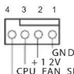
FAN_SPEED_CONTROL
CPU_FAN_SPEED
TaMaTePnHcKa
IIIata cha6keha
4-KOHTaKTHbIM pa3beMOM JIIMAIIOHmYMaIIeIero
BeHTnJIbTopa IIII. EcIN Bbl co6npaTeCb IIOKIIIOUHTb
3-KOHTaKTHbIi
BeHTIITOP OXIAJKeHnI IPOUeCCopa,IOKIIIOuayI erO K KOHTaKTam 1-3.
Pa3bEmIITaHnAATX
(24-KOHTaKTHbI, ATXPWR1)
(Cm. ctp. 1 nn 2, N° 12)
TaMaTePnHcKaIⅡaTa Cha6KeHa 24-KoHTaKTHbIM pa3BeMOM IITaHnA ATX.
TUTo6bI NcIOJIb3OBaTb
20-KOHTaKTHbI
pa3bEm HHTaHnA ATX, IIOIKIIOHNTe eRO BIOJIb
KOHTAKTa 1 N KOHTAKTa 13.
HaipjkeHne 2nd COMP II
1,5VPCH:
HannpJKeHne PCH 1,5V
1,05PCH:
HapnjaKeHne PCH 1,05V
VCCM:
HapjkeHne DRAM
VCC-in
BxoHoe HapnKeHne II
IO:
HaipKcHnBBOa-BBBOa
UII
GFX:
GFX LII (rpaΦnueckoe
Jnpo),HaipjKeHne
SA:
HaipjKeHne cntEmHO
arehta II
RING:
HaipjKeHne KoIbua
3aunntbI III (KaII)
VCOMP:
HapnKaHeNcOMP IIT
CORE0:
HaipjkeHne CORE0IIT
1.5 ΘneKtpoHHbIe KHONKN
MaTePnHcKa IIaTa CHa6KeHa TpeMg 3JIeKTPoHHbIMN KHOIIKaM: KHOIIKa IIITaHn, KHOIIKa Ipe3aRpy3Kn IIpeKJIIOuAteIb c6pOca HAcTpoEK CMOS, IIpeJHa3HaueHHbIMN IJIg 6bICTpORO BkJIIOUeHHN/BBIKJIIOUeHHN CnCTEmbl, Ipe3aRpy3Kn CnCTEmbl N O6HyJIeHHN 3HaueHHN CMOS.
IpeekHIOUaTeINITaHHNPCIE npEHa3HaueHIIBAKIOUeHNnIBbIKIOUeHNcoOTBeTCTBHyOuNXrHe3iPCIE x16.EcIn OJHa n3ycTaHOBJeHHbIX KapT PCIEx16 He pa6oTaET,NCIOJIb3yIteIpeEKIOUaTeINb IITaHNPiCe,HTo6bIoPpeJeNTbHeNCpPaBHyo KapTy 6e3CHHTN KAPT.

- BbKIOUme numaHue cucmembI nepeu uzmehnue noLoxhennepeKIOUameJI.
- Ecnu Kapma PCIE nnoxo ckonfusypupobana, oHa moKem c0epmb npu u3MeHenu nooKeHna nepkauamena numanua PCIe. 3a nodpo6bmu cbeHmu oxapakmepcmu kapmbi obpaauaumecb kee nocmauiky.
- Ipeekuamemnb numanua PCIe npedna3haen monbko dno omadku. Ecu kapma PCIE he uonblyemc, chumme eo c mamepuhnckou narnbl.
IpeKJIIOuAteIb MeJIeHHOrO peKIma pa60tB (SLOWMODE1) (CM. cTp. 1 m2, N 17)
EcnB BKIOUeH MeIeHHbI peKIM pa6OtBI, IPOueCCOP pa6OtaET Ha caMOH HN3KOJ qactote.
CelenkTophny
IpepeKIOUaTeJIb
BIOS(BIOS_SEL1)(CM.
ctp.1 nnn 2, No 32)
CenekTopbI IpekeKIOaTeB BIOS npedHa3HaueH ⅡIA 3aIycka cnCTeMbIC NcIOJIb3OBAHNem BIOS A INBIOS B.

mama mamepuuckaa nama cna6kena 6bmy Mukpcxemamu BIOS - ochnoiu BIOS (BIOS_A) u BIOS pe3epbno2o konupobunra (BIOS_B), - um noobnuaem ypoenb 3auumbu u cmaubnocmu cuminemb. Obucho cuminema ucnolbyem ochnohyo BIOS. Ipu nobpekdenuu uuc6oe ochnoiu BIOS npocmo ycmanohume cenekmopnbne nepeknouamel b BIOS b nookhenue «B», u npu cdeynouem zanycke cuminemb bydem ucnolb3oabmbc pe3epbnai BIOS. Iocne 3mo2o b yumune hacmpouku UEFI ucnolb3yume onuuo Secure Backup UEFI, umo6bl binnunmb konupobanue paobux fauiob BIOS B ochnohyo BIOS dnn oboceuenu hopmaibho paobmbu cuminemb. Iain oboceuenu 6e3onachocmu pyuhoe obnohienue pe3epbnoi konuu BIOS noIb3oabenem omKluyeho. Onpeoumb, kakaia BIOS ucnolb3yemca b hacmonuee bpemh, moKnho no cbemoduohom undukamopam BIOS (BIOS_ A_LED uu BIOS_B_LED).
IpekeIOUaTeJIb peKIMa
LN2
(LN2MODE1)
(Cm. ctp. 1 nIN 2, No 18)
Pekm LN2 nioJb3yetc
IIy ycTpaHeHH c6oEB
3KCTpeMaIbHO pa30rHaHHoro
IPOueccopa cOxlaXeHneM
KIMa3OTOM IIpi
"XoIOHOH"HaHaJIbHOH
3aRpy3Ke.
1 Introdução
OC Formula Monitor Kiti
CPU
(OC)/1600/1333/1066 bellegi destekler
Genisletme
(bkz.s.1 veya 2,No.27)
Guc anahtarini baglayin, kasa uzerindeki anahtar ile system durumu belirtecini asagidaki pim duzenine gore sifirlayin. Kablolari baglarken positif ve negatif pimleri not edin.

PWRBTN (Guc Anahtart):
RESET (Stfirlama Anahtar):
(bkz.s.1 veya 2,No.25)
DUMMY SPEAKER
(3-pin CHA_FAN2) (bkz.s.1 veya 2, No. 34)
(3-pin CHA_FAN3) (bkz.s.1 veya 2, No.19)
(3 pimli CHA_FAN4) (bkz.s.1 vya 2, No. 42)

(3-pin PWR_FAN1) (bkz.s.1 veya 2, No.41)
(3 pimli MOS_FAN1) (bkz. s.1 vya 2, No. 43)
CPU Fan Baglayicilari (4-pin CPU_FAN1) (bkz.s.1 veya 2, No.3)
(3-pin CPU_FAN2) (bkz.s.1 veya 2, No.4)
ATX Guc Baglayicis1 (24-pin ATXPWR1) (bkz.s.1 veya s.2, No. 12)
(bkz.s.1 veya.s.2, No. 2)
Bu anakart, 8-pin ATX
12V guç baglayicsi
(Voltage Multi-adjustment)
支持光盘
MediaEspresso 6.5 试用版、Google Chrome 浏览器和工具栏、Start8、MeshCentral、Splashtop Streamer
硬件
机箱风扇速度)
操作系统
认证
VCOMP2: CPU 2nd COMP 电压
1.5VPCH:PCH1.5V电压
1.05PCH:PCH1.05V电压
VCCM:
DRAM电压
VCC-in: CPU输入电压
10: CPUIO电压
GFX:
CPU GFX(图形)电压
SA:CPU系统代理电压
RING: CPU Ring(缓存)电压
VCOMP: CPU COMP 电压
CORE0:
CPU CORE0 电压
1.5 智能开关
Kit Monitor OC Formula
CPU
Pentium®/Celeron® dalam Paket LGA1150
Chipset
Z87
Memori
(OC)/2133(OC)/1866(OC)/1600/1333/1066 non-ECC, memori tanpa buffer
Slot Ekspansi
x16 (PCIE1); dua pada x8 (PCIE1)/x8 (PCIE4); tiga pada x8 (PCIE1)/x4 (PCIE2)/x4 (PCIE4))
RESET (Switch Atur Ulang):
Jika Mode Lambat diaktifkan,
If you need to contact ASRock or want to know more about ASRock, you're welcome to visit ASRock's website at http://www.asrock.com; or you may contact your dealer for further information. For technical questions, please submit a support request form at http://www.asrock.com/support/tsd.asp
ASRock Incorporation
2F., No.37, Sec. 2, Jhongyang S. Rd., Beitou District,
Taipei City 112, Taiwan (R.O.C.)
ASRock EUROPE B.V.
Bijsterhuizen 3151
6604 LV Wijchen
The Netherlands
Phone: +31-24-345-44-33
Fax: +31-24-345-44-38
ASRock America, Inc.
13848 Magnolia Ave, Chino, CA91710
U.S.A.
Phone: +1-909-590-8308
Fax: +1-909-590-1026
- Copyright Notice:
- Disclaimer:
- CALIFORNIA, USA ONLY
- Motherboard Layout
- Z87 OC Formula/ac
- No.Description
- I/O Panel
- No. Description No. Description
- Chapter 1 Introduction
- Package Contents
- Specifications
- Audio
- LAN
- Rear Panel
- I/O
- Storage
- Connector
- BIOS
- Feature
- Unique Features
- ASRock Formula Drive
- ASRock Instant Flash
- ASRock APP Charger
- ASRock XFast USB
- ASRock XFast LAN
- ASRock XFast RAM
- ASRock Crashless BIOS
- ASRock OMG (Online Management Guard)
- ASRock Internet Flash
- ASRock UEFI System Browser
- ASRock Dehumidifier Function
- ASRock Easy RAID Installer
- ASRock Easy Driver Installer
- ASRock Interactive UEFI
- ASRock Fast Boot
- ASRock Restart to UEFI
- NickShih's OC Profile
- Fine-Tuning V-Controller
- Timing Configurator
- ASRock Good Night LED
- ASRock USB Key
- ASRock Conformal Coating
- ASRock Home Cloud
- Status OLED
- ASRock FAN-Tastic Tuning
- ASRock Distortion-Free Slot
- WiFi-802.11n Module and ASRock WiFi 2.4GHz Antenna (for Z87 OC Formula/ac only)
- Installing the SMA Wi-Fi Antenna Cables
- Step 1
- Step 2
- Step3
- Step 4
- Chapter 2 Installation
- Pre-installation Precautions
- Installing the CPU
- Installing the CPU Fan and Heatsink
- Installing Memory Modules (DIMM)
- Dual Channel Memory Configuration
- Expansion Slots (PCI and PCI Express Slots)
- PCIE slots:
- PCIE Slot Configurations
- Jumpers Setup
- Onboard Headers and Connectors
- PWRBTN (Power Switch):
- RESET (Reset Switch):
- PLED (System Power LED):
- HDLED (Hard Drive Activity LED):
- Smart Switches
- Einleitung
- Formula
- Processeur
- Chipset
- Memoire
- Fente
- d'expansion
- Kit Monitor OC Formula
- CPU
- Ranura de expansión
- Gráficos
- Oc06eHHoCTM
- DnckcN0
- KoHTpoJIb
- OC
- CepTuΦnKaζη
- yctaHObKa nepembyueK
- ΘneKtpoHHbIe KHONKN
- Introdução
- Genisletme
- PWRBTN (Guc Anahtart):
- RESET (Stfirlama Anahtar):
- 支持光盘
- 硬件
- 操作系统
- 认证
- 智能开关
- Memori
- Slot Ekspansi
- RESET (Switch Atur Ulang):
- ASRock Incorporation
- ASRock EUROPE B.V.
- ASRock America, Inc.
Brand : ASROCK
Model : Z87 OC Formula
Category : Motherboard