
ARP Odyssey FSQ - Synthesizer KORG - Free user manual and instructions
Find the device manual for free ARP Odyssey FSQ KORG in PDF.
| Product Type | Analog Duophonic Synthesizer |
| Brand | Korg |
| Model | ARP Odyssey FSQ |
| Dimensions (ARP Odyssey) | 502 × 380 × 120 mm |
| Dimensions (Module) | 496 × 265 × 89 mm |
| Weight (ARP Odyssey) | 5 kg |
| Weight (Module) | 3.7 kg |
| Power Supply | DC 9 V AC adapter (included), power consumption 6.5 W |
| Keyboard | 37 Slimkey keys, no velocity or aftertouch |
| Polyphony | 2 voices in duophonic mode, 1 voice in monophonic mode |
| Sound Generators | 2 VCO (sawtooth, square, pulse waves), VCF (low-pass filter with resonance), VCA |
| Filter Types | Selectable: Rev.1, Rev.2, Rev.3 (original ARP versions) |
| Modulation | LFO, Sample & Hold, ADSR and AR envelope generators |
| MIDI Connectivity | MIDI IN, USB Type B |
| Audio Outputs | LOW (6.3 mm mono jack), HIGH (XLR), headphone (6.3 mm stereo jack) |
| External Audio Input | 6.3 mm mono jack (EXT AUDIO INPUT) |
| Control Inputs/Outputs | CV IN/OUT, GATE IN/OUT, TRIG IN/OUT (3.5 mm jack) |
| Other Connectors | PEDAL (6.3 mm jack), PORTAMENTO FOOTSWITCH (6.3 mm jack) |
| Special Functions | Portamento, transposition, PPC (Proportional Pitch Control) control, oscillator sync, automatic power-off |
| Included Accessories | AC adapter, jack cable, mini-jack cable, user manual |
| Options | Volume pedal VP-10, foot switch PS-1/PS-3 |
| Maintenance and Cleaning | Clean with a dry, clean cloth. Do not use liquid products (benzene, thinner) or flammable substances. |
| Safety | Avoid exposure to heat, humidity, dust, vibrations, magnetic fields. Do not spill liquid on the device. Unplug if a metallic object enters. |
| Repairability | Contact your Korg dealer or after-sales service for any repairs. |
Frequently Asked Questions - ARP Odyssey FSQ KORG
User questions about ARP Odyssey FSQ KORG
0 question about this device. Answer the ones you know or ask your own.
Ask a new question about this device
Download the instructions for your Synthesizer in PDF format for free! Find your manual ARP Odyssey FSQ - KORG and take your electronic device back in hand. On this page are published all the documents necessary for the use of your device. ARP Odyssey FSQ by KORG.
USER MANUAL ARP Odyssey FSQ KORG
Thank you for purchasing the ARP ODYSSEY/ARP ODYSSEY Module Duophonic synthesizer. To help you get the most out of your new instrument, please read this manual carefully.
Precautions
Location
Using the unit in the following locations can result in a malfunction.
- In direct sunlight
- Locations of extreme temperature or humidity
- Excessively dusty or dirty locations
- Locations of excessive vibration
- Close to magnetic fields
Power supply
Please connect the designated AC adapter to an AC outlet of the correct voltage. Do not connect it to an AC outlet of voltage other than that for which your unit is intended.
Interference with other electrical devices
Radios and televisions placed nearby may experience reception interference. Operate this unit at a suitable distance from radios and televisions.
Handling
To avoid breakage, do not apply excessive force to the switches or controls.
Care
If the exterior becomes dirty, wipe it with a clean, dry cloth. Do not use liquid cleaners such as benzene or thinner, or cleaning compounds or flammable polishes.
Keep this manual
After reading this manual, please keep it for later reference.
Keeping foreign matter out of your equipment
Never set any container with liquid in it near this equipment. If liquid gets into the equipment, it could cause a breakdown, fire, or electrical shock.
Be careful not to let metal objects get into the equipment. If something does slip into the equipment, unplug the AC adapter from the wall outlet. Then contact your nearest Korg dealer or the store where the equipment was purchased.
- All product names and company names are the trademarks or registered trademarks of their respective owners.
DECLARATION OF CONFORMITY (for USA)
Responsible Party: KORG USA INC.
Address:316 SOUTH SERVICE ROAD, MELVILLE, NY
Telephone: 1-631-390-6500
Equipment Type: Duophonic synthesizer
Model: ARPODYSSEY, ARPODYSSEY-M
This device complies with Part 15 of FCC Rules.
Operation is subject to the following two conditions:
(1) This device may not cause harmful interference, and
(2) this device must accept any interference received,
including interference that may cause undesired operation.
THE FCC REGULATION WARNING (for USA)
NOTE: This equipment has been tested and found to comply with the limits for a Class B digital device, pursuant to Part 15 of the FCC Rules. These limits are designed to provide reasonable protection against harmful interference in a residential installation. This equipment generates, uses, and can radiate radio frequency energy and, if not installed and used in accordance with the instructions, may cause harmful interference to radio communications. However, there is no guarantee that interference will not occur in a particular installation. If this equipment does cause harmful interference to radio or television reception, which can be determined by turning the equipment off and on, the user is encouraged to try to correct the interference by one or more of the following measures:
Reorient or relocate the receiving antenna.
- Increase the separation between the equipment and receiver.
- Connect the equipment into an outlet on a circuit different from that to which the receiver is connected.
- Consult the dealer or an experienced radio/TV technician for help.
If items such as cables are included with this equipment, you must use those included items.
Unauthorized changes or modification to this system can void the user's authority to operate this equipment.
Notice regarding disposal (EU only)
When this "crossed-out wheeled bin" symbol is displayed on the product, owner's manual, battery, or battery package, it signifies that when you wish to dispose of this product, manual, package or battery you must do so in an approved manner.
Do not discard this product, manual, package or battery along with ordinary household waste. Disposing in the correct manner will prevent harm to human health and potential damage to the environment. Since the correct method of
disposal will depend on the applicable laws and regulations in your locality, please contact your local administrative body for details. If the battery contains heavy metals in excess of the regulated amount, a chemical symbol is displayed below the "crossed-out wheeled bin" symbol on the battery or battery package.
Table of Contents
Introduction to the ODYSSEY. 4
What is the ODYSSEY? 4
Main Features 4
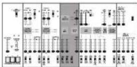
Block diagram. 5
Panel description and functions 6
Front panel (Noise type, Controller section) 6
Front panel (VCO-1 section) 7
Front panel (VCO-2 section) 8
Front panel (LFO, SAMPLE AND HOLD section) 9
Front panel (AUDIO MIXER, VCF, HPF, VCA section) 10
Front panel (ENVELOPE GENERATOR section) 12
Rear panel. 13
Getting started. 14
Connections. 14
Turning the power on 15
Turning the power off 15
Auto power-off function. 15
Let's make some sounds 16
Basic settings. 16
Tuning 16
About MIDI 17
Connecting MIDI devices 17
Connecting a computer 18
About the MIDI implementation chart. 18
Troubleshooting 18
Specifications 18
This manual explains the ARP ODYSSEY and the ARP ODYSSEY Module. Unless we specify otherwise, the panel illustrations are of the ARP ODYSSEY.
Introduction to the ODYSSEY
What is the ODYSSEY?
The ODYSSEY was manufactured from 1972 through 1981 by the ARP Corporation, and was one of their best-known products.
Broadly speaking, there are three versions according to their date of production, and these three differ in appearance, as well as in tonal character and functionality.
Model 2800 is known as Rev.1; this includes the initial white-panel model produced from 1972 to 1974 and the black-panel model produced from 1974 to about 1975.
Models 2810 - 2813 are known as Rev. 2; these consist of the black-panel models which were produced from 1975 to about 1976. Changes were made to the filter, and changes were also made to the oscillator of some models. External audio input and CV/GATE input jacks were also added, and later models changed the knob-style pitch bender to a PPC (Proportional Pitch Control).
Models 2820 - 2823 are known as Rev. 3, and were produced from 1978 to about 1981. The panel changed to a black panel with orange silk-screening and the design also changed significantly from models 2800 - 2813. The audio output was also changed from RCA/PHONE to XLR/PHONE jacks.
Main Features
The traditional analog VCO, VCF, and VCA circuitry of the ARP ODYSSEY. This provides the high degree of sound-editing spontaneity that is uniquely offered by analog synthesis.
- 37-note slimkey bed that covers a pitch range of seven octaves. [The ARP ODYSSEY Module is a keyboard-less model]
- You can play the instrument monophonically, or use duophonic mode that sounds the oscillators at independent pitches when you play two keys simultaneously. (However, there is only one filter and one amp.)
- Two types of envelope generators are provided: ADSR type and AR type.
- Oscillator sync. This feature is valued for generating numerous high-frequency overtones and for its sharpness.
- The PPC (Proportional Pitch Control) using the original rubber pad has been reproduced.
Modulation can be applied in a wide variety of ways.
- Two types of noise are provided.
LFO and S&H are provided, and you can switch their routing.
- The filters from the three different types of ARP ODYSSEY are provided, and can be selected by a single switch.
- Since an external audio input jack is provided, you can also process the sound of an external musical instrument.
- A USB port and MIDI connectors are provided, allowing you to connect a PC or a MIDI instrument.
Block diagram
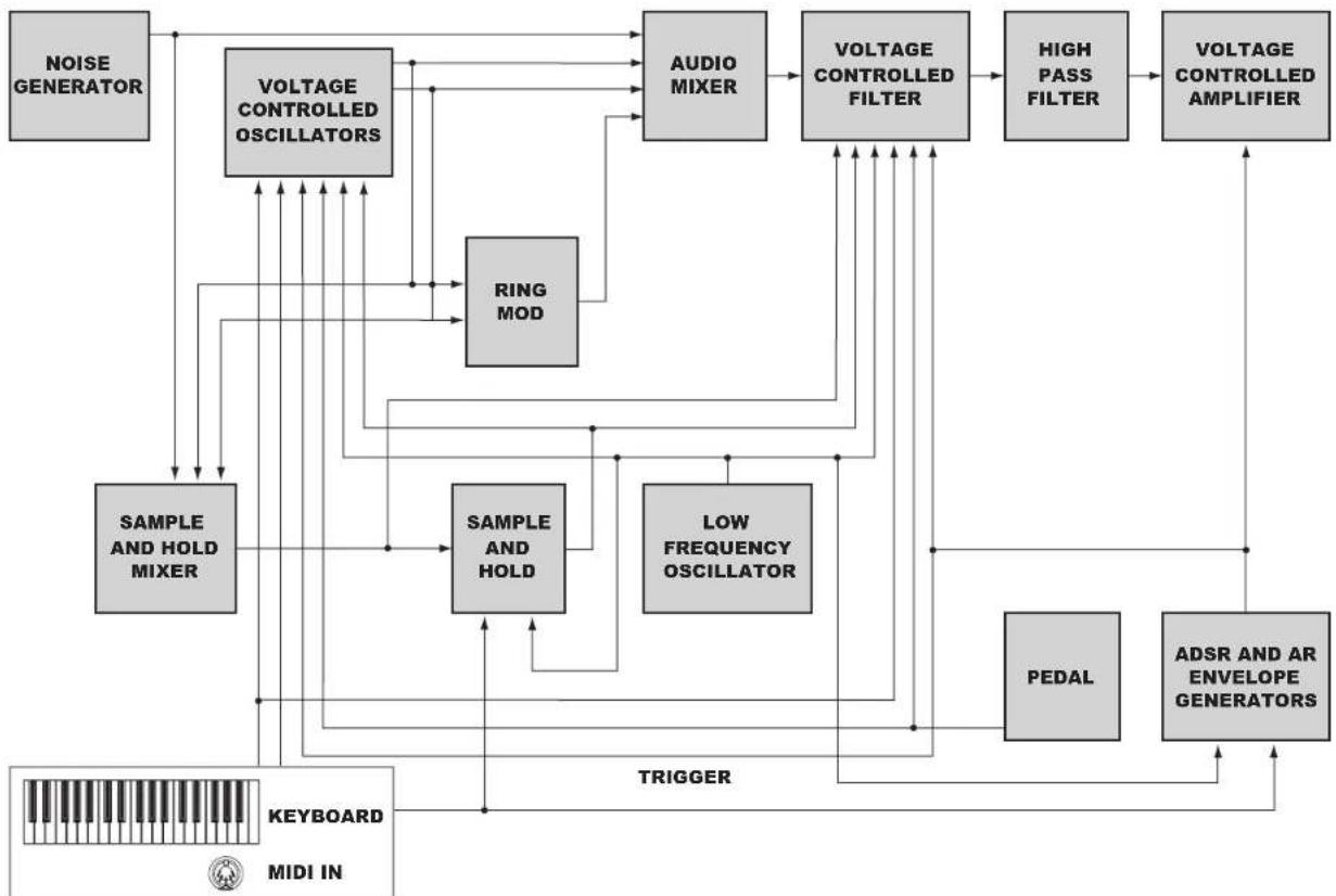
ARP ODYSSEY: Built-in Keyboard and MIDI IN ARP ODYSSEY Module: Only MIDI IN
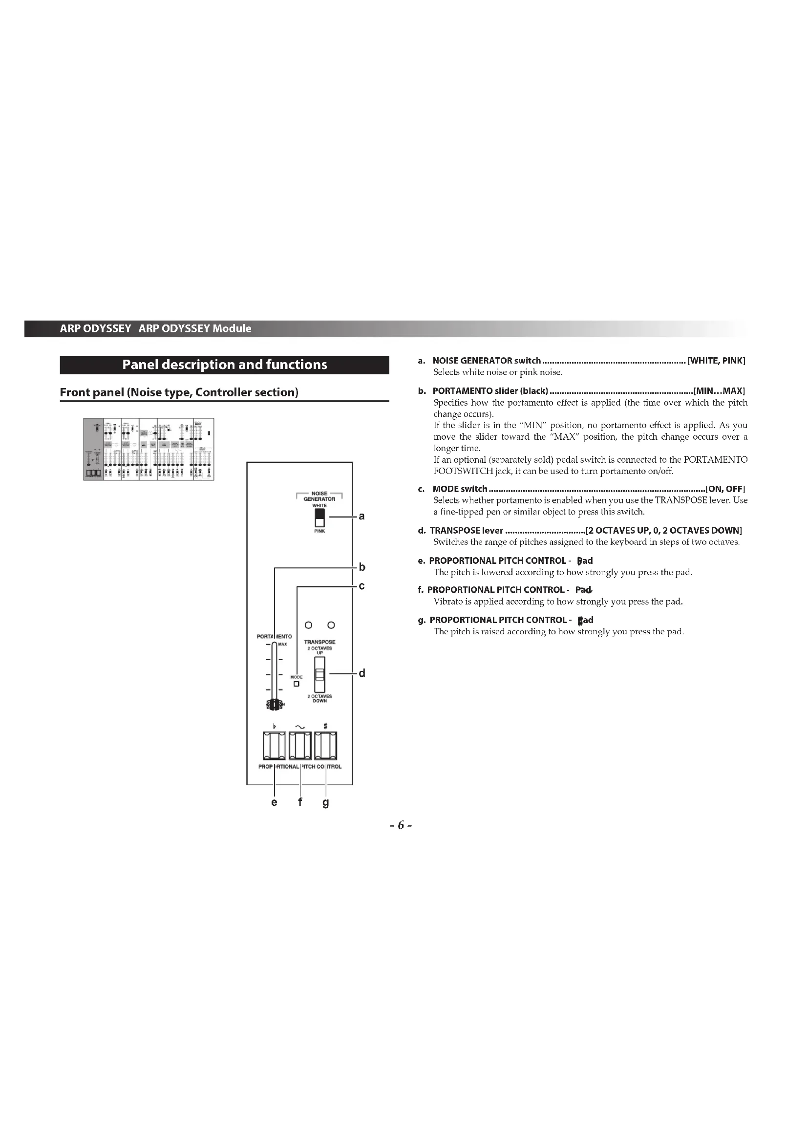
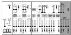
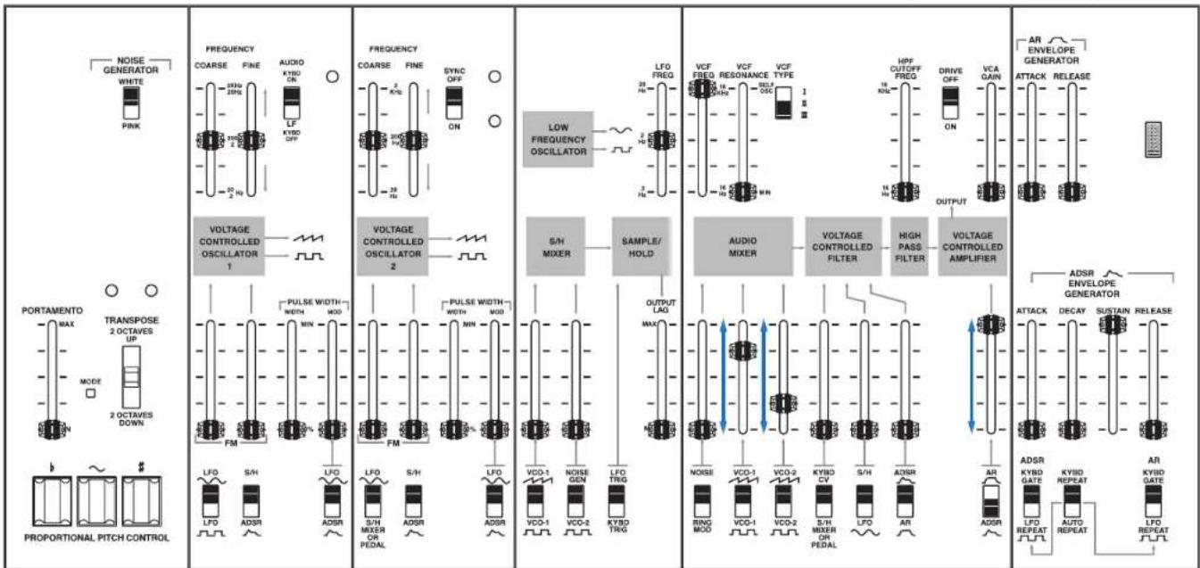
Panel description and functions
Front panel (Noise type, Controller section)
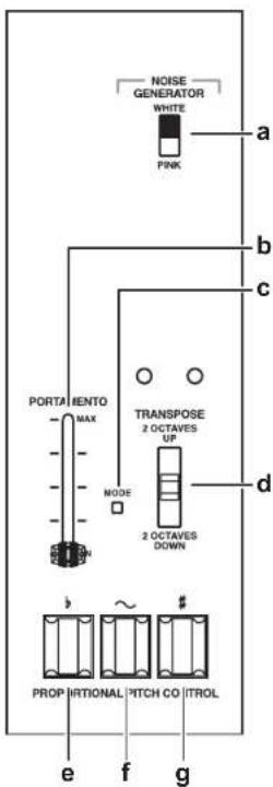
a. NOISE GENERATOR switch.. [WHITE, PINK] Selects white noise or pink noise.
b. PORTAMENTO slider (black) [MIN...MAX] Specifies how the portamento effect is applied (the time over which the pitch change occurs). If the slider is in the "MIN" position, no portamento effect is applied. As you move the slider toward the MAX position, the pitch change occurs over a longer time. If an optional (separately sold) pedal switch is connected to the PORTAMENTO FOOTSWITCH jack, it can be used to turn portamento on/off.
c. MODE switch.. [ON, OFF] Selects whether portamento is enabled when you use the TRANSPOSE lever. Use a fine-tipped pen or similar object to press this switch.
d. TRANSPOSE lever.[2 OCTAVES UP,0,2 OCTAVES DOWN] Switches the range of pitches assigned to the keyboard in steps of two octaves.
e. PROPORTIONAL PITCH CONTROL - Bad The pitch is lowered according to how strongly you press the pad.
f. PROPORTIONAL PITCH CONTROL - Pad Vibrato is applied according to how strongly you press the pad.
g. PROPORTIONAL PITCH CONTROL - pad The pitch is raised according to how strongly you press the pad.
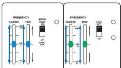
Front panel (VCO-1 section)
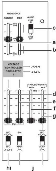
The following settings are for oscillator 1 (VCO-1).
a. FREQUENCY COARSE slider (blue).[20(0.2)Hz...2K(20)Hz]
Rough pitch adjustment.
This adjustment covers the range of 20Hz - 2kHz if the keyboard switch is on, or 0.2Hz - 20Hz if the keyboard switch is off.
The frequency range (20Hz - 2kHz) is an approximate value.
b. FREQUENCY FINE slider (blue). [±400cent] Fine pitch adjustment.
c. Keyboard switch.[AUDIO KYBD ON, LF KYBD OFF] If this is set to AUDIO KYBD ON, VCO-1 is connected to the keyboard CV, and will produce pitches in the conventional way. If this is set to AUDIO KYBD OFF, VCO-1 is disconnected from the keyboard CV, and will oscillate as an LFO. You can use this signal to modulate VCO-2 or as an audio source for sound effects.
d. FM depth slider (pink)
e. FM depth slider (yellow)
Adjusts the depth of FM (Frequency Modulation) when it is applied.
f. PULSE WIDTH (WIDTH) slider (blue).[50%...MIN]
Adjusts the pulse width.
g. PULSE WIDTH (MOD) slider (pink)
Adjusts the depth of pulse width modulation.
h. FM source switch [LFO LFO]
Selects the waveform of the modulation applied by the LFO.
i. FM source switch [S/H, ADSR]
Selects either Sample and Hold or the envelope generator (ADSR) as the modulation source.
j. Pulse width modulation souece switch..[LFO ADSR
Selects the source that will apply pulse width modulation.
Front panel (VCO-2 section)
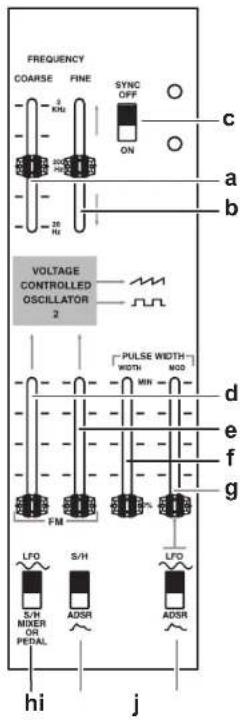
The following settings are for oscillator 2 (VCO-2).
a. FREQUENCY COARSE slider (green) [20(0.2)Hz...2K(20)Hz]
Rough pitch adjustment. This is adjustable in the range of 20Hz - 2kHz If the SYNC switch is on, this changes the overtone structure rather than the pitch.
The frequency range (20Hz - 2kHz) is an approximate value.
b. FREQUENCY FINE slider (green) [±400cent] Fine pitch adjustment.
If the SYNC switch is on, this changes the overtone structure rather than the pitch.
c. SYNC switch OFF, ON Turns sync on/off.
If this is off, duophonic performance is possible. If this is on, VCO-2 is synchronized with the frequency (pitch) of VCO-1.
d. FM depth slider (pink)
e. FM depth slider (yellow)
Adjusts the depth of FM (Frequency Modulation) when it is applied.
f. PULSE WIDTH (WIDTH) slider (blue).[50%...MIN]
Adjusts the pulse width.
g. PULSE WIDTH (MOD) slider (pink)
Adjusts the depth of pulse width modulation.
h. FM source switch [LFO, SUMIXER OR PEDAL]
Selects either modulation by an LFO sine wave or modulation by the S/H MIXER (sample and hold mixer) or pedal signal.
If you select S/H MIXER OR PEDAL, the modulation can be controlled by an optional (separately sold) volume pedal connected to the pedal jack.
i. FM source switch [S/H, ADSR]
Selects either Sample and Hold or the envelope generator (ADSR) as the modulation source.
j. Pulse width modulation souece switch [LFO ADSR
Selects the source that will apply pulse width modulation.
Front panel (LFO, SAMPLE AND HOLD section)
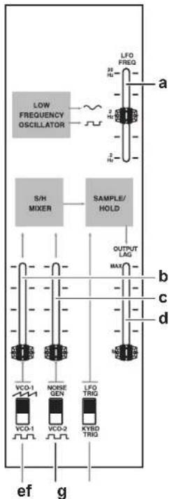
a. LFO FREQ (LFO speed) slider (pink). [0.2Hz..20Hz]
Adjusts the LFO speed.
Raising the slider makes the speed faster.
b. S/H input level slider (blue)
Adjusts the level at which the waveform output from VCO-1 is input to the S/H MIXER.
c. S/H input level slider (white)
Adjusts the level at which noise or the square wave output from VCO-2 is input to the S/H MIXER.
d. S/H OUTPUT LAG slider (yellow)
Smooths the changes of the S/H output voltage.
As you move the slider toward the "MAX" position, a greater amount of the smoothing will be applied.
e. S/H input source switch [VCO-1, VCO-1]
Selects the source (VCO-1 waveform) that is input to the S/H MIXER.
f. S/H input source switch [NOISE GEN, VCO-2]
Selects the source (noise or VCO-2 square wave) that is input to the S/H MIXER.
g. S/H trigger source switch.[LFO TRIG, KYBD TRIG]
Selects the signal (either the output of the LFO or the output of the keyboard) that is used as the trigger when detecting an audio signal sent from the S/H MIXER.
Front panel (AUDIO MIXER, VCF, HPF, VCA section)
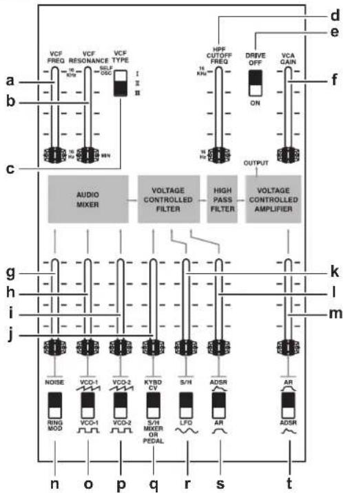
a. VCF FREQ slider (black). [16Hz..16KHz] Adjusts how the LPF (Low Pass Filter) is applied. If the slider is in the lowest position (16 Hz), the high-frequency range of the input signal is cut, producing a soft sound. Raising the slider makes the sound brighter.
b. VCF RESONANCE slider (black) [MIN...SELF OSC] Adjusts the resonance.
This modifies the tonal character by boosting the overtones in the region of the cutoff point. As you raise the slider, self-oscillation (a state in which the VCF itself produces a sound) will occur starting at a certain point.
c. VCF TYPE switch [I II III]
Selects the type of VCF.
I: ODYSSEY Rev. 1
I: ODYSSEY Rev. 2
Ⅲ:ODYSSEY Rev.3
d. HPFCUTOFFFREQslider(black) [16Hz..16KHz]
Adjusts how the HPF (High Pass Filter) is applied.
As you raise the slider, the low-frequency region of the input signal is cut, producing a thinner sound. This is useful when you are simulating the sound of certain instruments.
e. DRIVE switch [OFF, ON]
By turning this on you can make the VCA distort.
f. VCA GAIN slider (black)
Adjusts the volume at which the audio signal always passes through the VCA.
g.NOISE/RING MOD slider (white)
Adjusts the level of the audio signal that is sent from the noise generator or the ring modulator.
h. VCO-1 volume slider (blue)
Adjusts the level of the audio signal that is sent from VCO-1.
i. VCO-2 volume slider (green)
Adjusts the level of the audio signal that is sent from VCO-2.
j. Filter modulation level slider (black)
Adjusts the level of the signal that controls the VCF FREQ, or adjusts how the signal sent from the S/H MIXER opens and closes the filter.
k. Filter modulation level slider (yellow)
Adjusts how the filter is opened and closed by S/H (sample and hold) or the LFO.
I. Filter modulation level slider (pink)
Adjusts how the two envelope generators (AR and ADSR) control the filter.
m. VCA level slider (red)
Adjusts the level at which the envelope generators (AR and ADSR) control the VCA. In practical terms, this is the master volume of the ARP ODYSSEY. If the DRIVE switch is on, this also adjusts the VCA distortion.
n. Filter input source (NOISE/RING MOD) switch [NOISE, RING MOD]
Selects either noise or ring modulator.
o.Filter input source (VCO-1 wave) switch.[VCO-1,VEO1]
Selects the VCO-1 waveform (sawtooth or square). If you select square wave, you can raise the PULSE WIDTH slider (page 7) to change from a square wave to a pulse wave.
p.Filter input source (VCO-2 wave) switch.[VCO-2, VCO-2]
- Selects the VCO-2 waveform (sawtooth or square).
- If you select square wave, you can raise the PULSE WIDTH slider (page 8) to change from a square wave to a pulse wave.
q. Filter modulation source (KYBD CV/S/H MIXER OR PEDAL) switch
[KYBD CV, S/H MIXER OR PEDAL]
Selects the source that will control the filter. If you select KYBD CV (keyboard control voltage), the signal normally used to convey key information from the keyboard to the VCO can be used to open and close the filter. For example, you can produce an effect in which the filter opens more for higher notes. If you select S/H MIXER OR PEDAL, the signal sent from the S/H MIXER will open and close the filter. If an optional (separately sold) volume pedal is connected to the PEDAL jack, you can use the signal of the pedal to control the VCF, producing an effect like a wah pedal.
r. Filter modulation source (S/H/LFO) switch [S/H, LFO]
Selects the source that will control the filter. You can produce a wah effect by using the LFO to modulate the filter.
s. Filter modulation source (ADSR/AR) switch..[ADSR,.. Selects the envelope generator that will control the filter.
t. VCA EG switch.[AR ADSR] Selects the envelope generator that will control the VCA.
Front panel (ENVELOPE GENERATOR section)
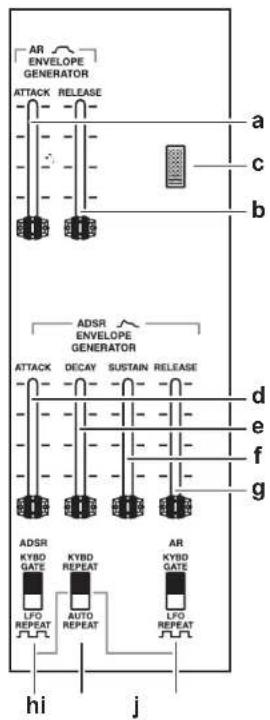
a. AR EG-ATTACK slider (red)
Adjusts the attack time of the AR envelope generator.
b. AR EG -RELEASE slider (red)
Adjusts the release time of the AR envelope generator.
c. Power LED
This is lit if the power is on, and is unlit if the power is off. If the auto power-off function is disabled, the LED blinks several times and then stays lit when you turn on the power.
d. ADSR EG-ATTACK slider (red)
Adjusts the attack time of the ADSR envelope generator.
e. ADSREG-DECAY slider (red)
Adjusts the decay time of the ADSR envelope generator.
f. ADSR EG - SUSTAIN slider (red)
Adjusts the sustain time of the ADSR envelope generator.
g.ADSREG-RELEASEslider(red)
Adjusts the release time of the ADSR envelope generator.
h. ADSR trigger source switch.[KYBD GATE, LFO REPEAT]
Selects the trigger that is sent to the ADSR envelope generator.
If KYBD GATE is selected, the trigger sent from the keyboard is sent to the EC. If LFO REPEAT is selected, the pulse wave of the LFO is sent to the EG, and the EG repeats the envelope cyclically at the rate of the LFO FREQ.
i. ADSR repeat switch.[KYBD REPEAT, AUTO REPEAT]
This is effective if LFO REPEAT is selected by the ADSR or by the AR trigger source switch.
If KYBD REPEAT is selected, the LFO trigger sent repeatedly to the EG continues repeating only as long as the key is pressed. If AUTO REPEAT is selected, it continues repeating regardless of the keyboard on/off status.
j. AR trigger source switch.[KYBD GATE, LFO REPEAT]
Selects the trigger that is sent to the AR envelope generator.
This has the same function as the ADSR trigger switch.
Rear panel
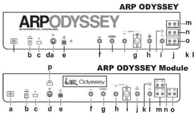
a. Cable hook
Wrap the AC adapter cable around this hook to prevent the AC adapter from being accidentally disconnected.
b. DC 9V jack
Connect the included AC adapter here. First connect the AC adapter to this instrument, and then connect the plug to an AC outlet.
c. Power switch
This turns the power on/off. To turn the power off, press and hold the switch.
d. MIDI IN connector
You can connect an external MIDI device to this connector to receive MIDI data.
e. USB B port
You can connect a computer to this port to transmit and receive MIDI data.
f. PEDAL jack
Connect an optional (separately sold) volume pedal here. You'll also use this jack when connecting the SQ-1 (sequencer) to control the ARP ODYSSEY.
Connect an optional (separately sold) pedal switch here.
h. OUTPUT LOW jack
Connect an amp or powered monitor speaker here.
I. OUTPUT HIGH Jack
Here you can connect a mixer or amp that is equipped with an XLR jack.
j. EXT AUDIO INPUT jack
If you're using the ARP ODSYSEY as an effect processor, use a monaural phone cable to connect your external audio source to this jack.
An external signal that is input to the EXT AUDIO INPUT jack is input to the AUDIO MIXER and passes through the VCF and VCA. Use the connected external device to adjust the volume.
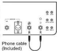
Tip: If you use the included phone jack cable to connect the EXT AUDIO INPUT jack to the headphone jack, self-feedback can be applied, expanding the range of sounds. Use the headphone volume to adjust the amount of feedback.
k. Headphone volume
Adjusts the volume of the connected headphones.
If self-feedback is being applied, this adjusts the amount of feedback.
I. Headphones jack
Connect your headphones here. This provides the same signal as the output from the OUTPUT LOW jack or OUTPUT HIGH jack. If you want to apply self-feedback, connect this jack to the EXT AUDIO INPUT jack of the ARP ODYSSEY.
m. CV IN/OUT jacks
These jacks input and output a control voltage (a voltage that indicates the pitch).
These jacks input and output a gate signal (a signal that sound is being produced).
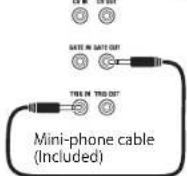
o. TRIG IN/OUT jacks
These jacks input and output a trigger (a signal that the keyboard is being pressed).
Tip: If you use the included mini-phone cable to connect the TRIG IN jack and the GATE OUT jack, the ADSR EG will not be retriggered, allowing you to play lcgato.
p. MODE SWITCH (ARP ODYSSEY Module only)
This switch lets you set the MIDI channel and the auto power-off setting.
When you operate the switch, the power LED blinks.
Getting started
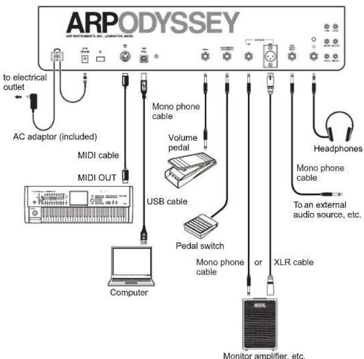
Connections
The following illustration shows an example of typical connections. Connect your equipment as appropriate for your needs.
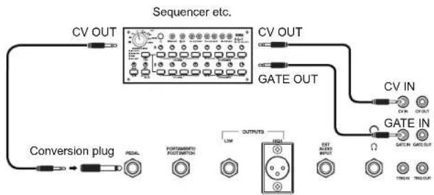
Other example connections
You can use patch cables to connect the ARP ODYSSEY to a sequencer as shown below, so that the sequencer can control the ARP ODYSSEY to produce sound. If you're connecting the ARP ODYSSEY with the SQ-1, connect the ARP ODYSSEY's PFDAL.Jack to the SQ-1's CV OUT jack so that the ARP ODYSSEY's VCO 2 pitch and filter can be controlled.
You must turn off the power of all devices before connecting anything. If you connect devices while the power is on, you might damage your speaker system or cause your equipment to malfunction or be damaged.
If you want to connect a pedal, use a monaural cable to connect the PEDAL jack of the ARP ODYSSEY to the OUT 1 or OUT 2 jack of an optional (separately sold) Korg VP-10 volume pedal. In this case, the MINIMUM VOLUME of the VP-10 must be set to 0 (minimized).
Tip: If you want to use a pedal switch to turn portamento on/off, connect an optional (separately sold) Korg PS-1 or PS-3 pedal switch to the PORTAMENTO FOOTSWITCH jack of the ARP ODYSSEY. Portamento turns off when you press the pedal switch; releasing the pedal switch applies the portamento effect at the time specified by the PORTAMENTO slider.
Turning the power on
Turn off the power of your powered monitor speakers or other external output device before you power-on the ARP ODYSSEY.
1. Lower the ARP ODYSSEY's VCA level slider (page 11) and VCA GAIN slider (page 10) to the minimum position.
2. Press the ARP ODYSSEY's power switch to turn the power on. The power LED will light up.
3. Lower the volume controls of your powered monitors or external output system, and then turn their power on.
4. Raise the volume controls of your powered monitors or external output system to an appropriate level, and adjust the ARP ODYSSEY's VCA level slider.
Tip: If you are not familiar with how to create sounds, we suggest that you now adjust the settings as described in the "Basic settings" section (page 16).
Turning the power off
- Lower the volume of your powered monitors or external output system, and turn their power off.
- Hold down the ARP ODYSSEY's power switch, and release it when the power LED goes dark.
Auto power-off function
The ARP ODYSSEY has an auto power-off function that automatically turns the power off when approximately four hours have elapsed since the instrument was last played or used. With the factory settings, the auto power-off function is enabled.
Changing the auto power-off setting
If desired, you can enable or disable the auto power-off function.
Do not turn off the power while you are changing this setting. Doing so may destroy data, causing a malfunction.
Tip: The setting of the auto power-off function is remembered even after you turn off the power.
Disabling the auto power-off function
ARP ODYSSEY
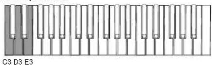
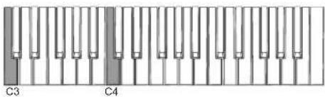
- While holding down the C3, D3, and E3 keys of the keyboard, press the power switch to turn the power on.
- When the power LED blinks several times and then remains lit, release the power switch. Each time you subsequently turn the power on, the power LED will blink, indicating that the auto power-off function is disabled.
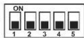
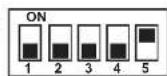
ARP ODYSSEY Module
Turn the rear panel MODE SWITCH 5 off (downward position). The auto power-off function is disabled; you don't have to turn the power off and on again to apply the setting.
Enabling the auto power-off function
ARP ODYSSEY
- While holding down the C3, D3, and F3 keys of the keyboard, press the power switch to turn the power on.
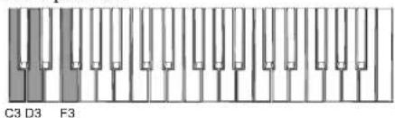
- When the power LED lights up, release the power switch. Each time you subsequently turn the power on, the power LED will light up immediately, indicating that the auto power-off function is enabled.
ARP ODYSSEY Module
Turn the rear panel MODE SWITCH 5 on (upward position). The auto power-off function is enabled; you don't have to turn the power off and on again to apply the setting.
Let's make some sounds
Basic settings
Set the ARP ODYSSEY's controls (滑行器, switches, etc.) as shown in the illustration below.
While you play the keyboard, gradually raise the VCO-1 volume slider (blue) or VCO-2 volume slider (green); you'll hear the sound of a sawtooth wave. Use the VCA level slider (red) to adjust the volume.
Tuning
After you've adjusted the basic settings as described above, use a commercially available tuner to adjust the FREQUENCY COURSE slider and FREQUENCY FINE slider to the correct pitch.
About MIDI
Connecting MIDI devices
By connecting the ARP ODYSSEY to a computer or external MIDI sequencer, you can control the sound generator of the ARP ODYSSEY from an external device.
Use a commercially available MIDI cable to connect the ARP ODSYSEy's MIDI IN connector to the MIDI OUT connector of your external MIDI device (see "Connections" on page 14).
MIDI IN connector: This receives MIDI messages from other MIDI devices. Connect this connector to the MIDI OUT connector of the other device.
Note messages (velocity is ignored) are the only type of MIDI messages that the ARP ODYSSEY can receive via its MIDI IN connector. The range of notes that can be received is 012 (C0) - 127 (G9).
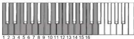
MIDI channel
MIDI has sixteen channels, 1-16.
If you connect an external MIDI device, you must set the MIDI channel of the ARP ODYSSEY to match the MIDI channel of your external MIDI device.
Setting the MIDI channel of the ARP ODYSSEY
Here's how to set the MIDI channel of the ARP ODYSSEY. With the factory settings, this is set to channel 1.
Tip: For details on how to set the MIDI channel of your external device, refer to its operating manual.
ARP ODYSSEY
- While holding down the C3 and C4 keys of the keyboard, press the power switch to turn the power on. The ARP ODYSSEY is in MIDI channel setting mode; the power LED blinks* to indicate the MIDI channel.
-
The LED repeatedly blinks to indicate the MID1 channel setting; once for channel 1, twice for channel 2, and so on.
-
MIDI channels (1 - 16) are assigned to the keyboard as follows. Press the key corresponding to the MIDI channel that you want to assign (e.g., press the D2 key to assign channel 2). The power LED continues blinking.*
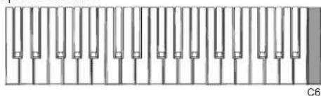
- Press the C6 key to save the MID1 channel setting. When the setting has been saved, the power turns off.
ARP ODYSSEY Module
Use the rear panel MODE SWITCH 1-4 to specify the MIDI channel. The MIDI channel settings are shown in the following table. The MIDI channel changes immediately when you change the setting.
Although you can change the MIDI channel during use, currently-sounding notes will turn off. Pitch bend is also reset.
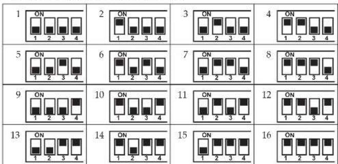
ARP ODYSSEY ARP ODYSSEY Module
Connecting a computer
Use a USB cable to directly connect the ARP ODYSSEY to a computer that's equipped with a USB port in order to receive MIDI messages in the same way as with the MIDI connectors. (see "Connections" on page 14) The MIDI messages that can be transmitted and received via the USB port are fixed at 1; note messages (with velocity fixed at 64 for transmission, and ignored for reception) can be transmitted and received. Since the ARP ODYSSEY Module has no keyboard, it cannot transmit note messages. The ARP ODYSSEY Module can receive MIDI pitch bend messages ( ± 2 semitones).
Tip: The only MIDI messages that are transmitted are note messages transmitted when the keyboard is played. Messages such as PROPORTIONAL PITCH CONTROL are not transmitted.
Tip: When connecting via USB, the KORG USB-MIDI driver must be installed. Download the KORG USB-MIDI driver from the Korg Web site ( http://www.korg.com/ ), and then install it according to the instructions in the document included with the driver.
About the MIDI implementation chart
The MIDI implementation chart lists the MIDI messages that can be transmitted and received. When using a MIDI device, compare the MIDI implementation charts to check that the MIDI messages are compatible. You can download the MIDI implementation chart for this device from the Korg website.
Tip: Detailed MIDI specifications are provided under MIDI implementation. For more information on MIDI implementation, visit the Korg Web site (http://www.korg.com/).
Troubleshooting
Power won't turn on.
- Is the AC adapter connected correctly?
No sound.
- Try setting the panel controls to the settings described in the "Basic settings" section (page 16).
- Is the ARP ODYSSEY correctly connected to the input jack of your amp, mixer, or headphones?
- Is your amp or mixer powered-on, and is the volume raided on that device?
- Could the VCA level slider (red; page 11) or the VCA GAIN slider (black; page 10) be set to "0"?
Does not respond to MIDI data sent from an external device.
- Is the MIDI cable or USB cable connected correctly? (see "Connections" on page 14)
- Docs the MIDI channel of the data being sent from the external MIDI device match the global MIDI channel of the ARP ODYSSEY? (see "MIDI channel" on page 17)
Can't input sound from an external audio source.
- Is the source being correctly input to the rear panel EXT AUDIO INPUT jack?
Can't reset pitch bend on the ARP ODYSSEY Module.
- Pitch bend can be reset by receiving a MIDI message such as Reset All Controllers. If you want to reset by operating this unit, you can turn the power off and on again, or you can operate a MODE SWITCH to temporarily change the MIDI channel.
Specifications
Operating temperature range: 0 - +40^ (non-condensing)
Keyboard (only ARP ODYSSEY): 37-note (slimkey, no velocity sensitivity, no aftertouch)
Maximum Polyphony: 2 voices for duophonic; normally monophonic
CONTROLLERS
Transpose positions: 2 octaves down, normal, 2 octave up
Proportional Pitch Control: (Pitch down) pad: about -2 / 3 octave
(Modulation) pad
(Pitch-up) pad: about +2 / 3 octave
Noise generator: Noise spectrum types (white and pink)
Portamento: Maximum speed: about 0.01 msec./oct
Minimum speed: about 1.5 sec./oct
VCO (Voltage Controlled Oscillator)
Waveforms: Sawtooth, square, pluse (dynamic pluse)
Frequency range: VCO-1 in low freq. mode, 0.2Hz - 20Hz VCO-1
and VCO-2 (audio range) about 20Hz - 20kHz
Warm up drift: 1/30 semitone from turn on max
Pulse width: 50% - 5%
Pulse width modulation: ADSR, +45%; LFO, +15%
Voltage controlled response: 1 V/act
Maximum frequency shifts: LFO sin wave, +1/2 oct.; LFO square wave, +1.5
oct.; ADSR, +9 oct.; S/H, +2 oct.
VCO-1 is low note priority, VCO-2 is high note priority.
VCF (Voltage Controlled Filter)
Types: Low pass (I: 12 dB/occt., II: III: 24 dB/occt.)
Frequency range: 16Hz - 16kHz
Maximum usable Q: 30
Resonance: 1/2 - self oscillate
Voltage controlled response: C3 key (left edge): 0 V, C6 key (right edge) 3 V
VCA (Voltage Controlled Amplifier)
Dynamic Range: 80 dB
RING MODULATOR
Type: Digital
Input signal: VCO-1, VCO-2 (square wave)
SAMPLE & HOLD
Command sources: Keyboard or LFO trigger
Sampled signals: VCO-1 sawtooth wave and square wave, VCO-2
square wave and pink noise
ADSR ENVELOPE GENERATOR
Attack time: 5 msec. -5 sec.
Decay time: 10 msec. -8 sec.
Sustain Level: 0 - 100% or Peak
Release time: 15 msec. -10 sec.
AR ENVELOPE GENERATOR
Attack time: 5 msec. -5 sec
Release time: 10 msec. -8 sec.
CONTROL INPUT JACKS
Pedal: 6.3mm monaural phone jack
Portamento foot switch: 6.3mm monaural phone jack
AUDIO OUTPUT JACKS
LOW
Connector: 6.3mm monaural phone jack
Maximum output level: -20 dBu@ 10 kΩ load
Output impedance: 10 kΩ
HIGH
Connector: XLR connector
Maximum output level: +4 dBu@ 1 kΩ load
Output impedance: 330Ω
HEADPHONES JACK
Connector:
6.3 ~mm stereo phone jack
Maximum output level: 50mW + 50mW@33 load
Output impedance: 10Ω
- Controllable by volume knob.
EXTERNAL AUDIO INPUT (EXT AUDIO INPUT) JACK
Connector: 6.3mm monaural phone jack
Maximum input level: -10 dBu
Input impedance:
22 kΩ
MIDI connector:
IN
USB connector: Type B
CV IN/OUT JACKS
Keyboard CV (IN/OUT):
1 V/occt.
Connector: 3.5mm monaural phone jack
GATE IN/OUT JACKS
GATE IN:
+3 V (minimum)
GATE OUT:
+10 V, key down; 0 V all keys up
Connector:
3.5 ~mm monaural phone jack
TRIG IN/OUT JACKS
TRIG IN:
+3 V pulse min., 10 μsec. duration minimum
TRIG OUT:
+10 V pulse on key depression, 10 μsec. duration
Connector: 3.5mm monaural phone jack
Power supply:
ACadapterjack(DC.9V
Power consumption:
6.5 W
Dimensions (W× D× H) Weight:
ARP ODYSSEY
502×380×120mm/19.76"×14.96"×4.72",
5kg / 11.02 lbs
ARP ODYSSEY Module
496 × 265 × 89 ~mm / 19.53^ × 10.43^ × 3.50^ ,
3.7kg / 8.16 lbs
Included items:
AC adapter, phone cable, mini-phone cable, owner's manual
Options:
VP-10 volume pedal, PS-1/PS-3 pedal switch
- Specifications and appearance are subject to change without notice for mprovement.
c. Commutateur de clavier [AUDIO KYBD ON, LF KYBD OFF]
i. Commutatee FM source [S/H, ADSR]
Adjusts the level of the audio signal that is sent from VCO-2.
Contrôleurs "Proportional Pitch Control" (PPC):
Pad (modulation)
VCO ("Voltage Controlled Oscillator")
VCF ("Voltage Controlled Filter")
Types: Passe-bas (I: 12 dB/occt., II III: 24 dB/occt.)
Plage de frquence: 16Hz 16kHz
Touche Do3 (bord gauche): 0 V, touche Do6 (bord
droit) 3 V
VCA (Voltage Controlled Amplifier')
Temps de chute (Decay):
10 ms - 8 sec.
c. Keyboard-Schalter [AUDIO KYBD ON, LF KYBD OFF]
(Modulation) Pad
Portamento: Maximum speed: about 0.01 msec./oct
VCO (Voltage Controlled Oscillator)
VCF (Voltage Controlled Filter)
VCA (Voltage Controlled Amplifier)
c. Conmutador MODE [ON, OFF]
[KYBD GATE, LFO REPEAT
Tecla C3 (borde izquierdo): 0 V, tecla C6 (borde
derecho) 3 V
c. VCF TYPEスイチ [I I]
VCFのターリフを選択しります。
I : ODYSSEY Rev.1
I : ODYSSEY Rev.2
I : ODYSSEY Rev. 3
i.ADSR1e-10s1tch.[KYBD REPEAT,AUTO REPEAT]
10msec. 8sec.
□nt口一儿·INsT端子
の英は日本国内載賬人た外国人の客様のたの注意事項です。
This Product is only suitable for sale in Japan. Properly qualified service is not
available for this product if purchased elsewhere. Any unauthorised modification or
removal of original serial number will disqualify this product from warranty protection.
客樣相談怒口
0570-666-569
This product has been manufactured according to strict specifications and voltage requirements that are applicable in the country in which it is intended that this product should be used. If you have purchased this product via the internet, through mail order, and/or via a telephone sale, you must verify that this product is intended to be used in the country in which you reside.
WARNING: Use of this product in any country other than that for which it is intended could be dangerous and could invalidate the manufacturer's or distributor's warranty.
Please also retain your receipt as proof of purchase otherwise your product may be disqualified from the manufacturer's or distributor's warranty.
- Precautions
- Location
- Power supply
- Interference with other electrical devices
- Handling
- Care
- Keep this manual
- Keeping foreign matter out of your equipment
- DECLARATION OF CONFORMITY (for USA)
- THE FCC REGULATION WARNING (for USA)
- Notice regarding disposal (EU only)
- Table of Contents
- Introduction to the ODYSSEY
- What is the ODYSSEY?
- Main Features
- Panel description and functions
- Front panel (Noise type, Controller section)
- Front panel (VCO-1 section)
- Front panel (VCO-2 section)
- Front panel (LFO, SAMPLE AND HOLD section)
- Front panel (AUDIO MIXER, VCF, HPF, VCA section)
- Front panel (ENVELOPE GENERATOR section)
- Rear panel
- a. Cable hook
- b. DC 9V jack
- c. Power switch
- d. MIDI IN connector
- e. USB B port
- f. PEDAL jack
- h. OUTPUT LOW jack
- OUTPUT HIGH Jack
- j. EXT AUDIO INPUT jack
- k. Headphone volume
- Headphones jack
- m. CV IN/OUT jacks
- o. TRIG IN/OUT jacks
- p. MODE SWITCH (ARP ODYSSEY Module only)
- Getting started
- Connections
- Other example connections
- Turning the power on
- Turning the power off
- Auto power-off function
- Changing the auto power-off setting
- Disabling the auto power-off function
- ARP ODYSSEY
- ARP ODYSSEY Module
- Enabling the auto power-off function
- Let's make some sounds
- Basic settings
- Tuning
- About MIDI
- Connecting MIDI devices
- MIDI channel
- Setting the MIDI channel of the ARP ODYSSEY
- ARP ODYSSEY ARP ODYSSEY Module
- Connecting a computer
- About the MIDI implementation chart
- Troubleshooting
- Power won't turn on.
- No sound.
- Does not respond to MIDI data sent from an external device.
- Can't input sound from an external audio source.
- Can't reset pitch bend on the ARP ODYSSEY Module.
- Specifications
- 客樣相談怒口
- 0570-666-569
Brand : KORG
Model : ARP Odyssey FSQ
Category : Synthesizer