Estate 3098 H2 - Tractor STIGA - Free user manual and instructions
Find the device manual for free Estate 3098 H2 STIGA in PDF.

| Product type | Ride-on lawn tractor |
| Brand | Stiga |
| Model | Estate 3098 H2 |
| Cutting width | 98 cm (MP98/SD98 series) |
| Cutting height | 3 to 8 cm (7 positions) |
| Transmission type | Mechanical (5 forward speeds + 1 reverse) or hydrostatic (continuous variable) |
| Maximum slope | 10° (about 17%) |
| Fuel tank capacity | About 6 litres (unleaded petrol) |
| Battery | 12 V, charge before first use and after storage |
| Front/rear tyres | Tyre pressure indicated on the machine (check before each use) |
| Guaranteed sound power level | See rating plate (about 96 dB(A)) |
| Vibration level at the driver's seat | See manual (indicative value) |
| Compatible accessories | Mulching kit, grass collector, side deflector, snow blade, trailer, spreader, lawn roller, etc. |
| Safety features | Engine shut-off if driver leaves seat, parking brake, ejection protection |
| Maintenance | Engine oil change (see manual), cleaning after each use, blade inspection |
| Storage | Empty fuel tank, disconnect battery, store in a dry sheltered place |
| Warranty | Manufacturer's warranty on material and manufacturing defects (excluding wear parts) |
Frequently Asked Questions - Estate 3098 H2 STIGA
User questions about Estate 3098 H2 STIGA
0 question about this device. Answer the ones you know or ask your own.
Ask a new question about this device
Download the instructions for your Tractor in PDF format for free! Find your manual Estate 3098 H2 - STIGA and take your electronic device back in hand. On this page are published all the documents necessary for the use of your device. Estate 3098 H2 by STIGA.
USER MANUAL Estate 3098 H2 STIGA
MP 84 Series
MP 98 Series
SD 98 Series
SD 108 Series

EN Ride-on lawnmower with seated operator - OPERATOR'S MANUAL
WARNING: read thoroughly the instruction booklet before using the machine.
[7]Pumpetryk for fordak
[8] Pumpetryk for bagdak
[9] Vægt (*)
[10] Minimumsradius af/DD kllppet graes
[11] Klippehøjde
[12] Klippebrede
[29] Malt lydefeftniveau
[30] Garanteret lydeffektniveau
[31] Vibrationsniveau pa fQRSdet
[42.A1, 42.A2] “Mulching
[42.C] Zugvorrichtung
[42.D] Abdeckung
[4] Electrical system
[5] Front tyres
[6] Rear tyres
[7] Front tyre pressure
[8] Rear tyre pressure
[9] Mass (*)
[10] Minimum radius of uncut grass
[11] Cutting height
[12] Cutting width
[13] Mechanical transmission Forward speed (approximate) at 3000 min-1
[14] Hydrostatic transmission Forward speed (approximate) at 3000 min^-1
[15] Speed limit with snow chains (if available)
[16] Dimensions
[17] Length
[18] Length with grass catcher (length without grass catcher)
[19] Width
[20] Width with side discharge chute (Width without side discharge chute)
[21] Height
[22] Cutting means code
[23] Fuel tank capacity
[24] Admissible load on towing device (maximum vertical weight)
[25] Admissible load for towing device (maximum towing weight)
[26] Maximum admissible tilt
[27] Acoustic pressure level
[28] Measurement uncertainty
[29] Measured acoustic power level
[30] Guaranteed acoustic power level
[31] Operator position vibration level
[32] Steering wheel vibration level
[33] Table for correct accessory combinations
[33.A] Rear accessories
[33.B] Front accessories
[42] Accessories available on request
[42.A1, 42.A2] “Mulching” kit
[42.B] Maintenance battery charger
[42.C] Towing kit
[42.D] Cloth cover
[42.E] Rear discharge guard kit (only for MP series)
[42.F] Snow chains (18")
[42.G] Mud / Snow wheels (18")
[42.H] Trailer
[42.I] Sprinkler
[42.J] Lawn roller
[42.K] Snow shovel
[42.L] Leaf and grass catcher (only for SD series)
- Please refer to the data indicated on the machine's identification plate for the exact figure.
[1] ES-DATOS TECNICOS
[2] Potencia nominal (*)
[42.K] Quitanieves de cucilla
[42.C] Kit remorquage
[42.D] Housse de protection
[33.A] Accessoires awhile
[26] Maks. tillatt helling
[27] Lydtrykkniva
[28] Måleusikkerhet
[29] Malt lydeffektniva
[30] Garantert lydefeftkniva
[42.A1, 42.A2] Mulching-sett
[42.B] Batterilader
[14] TnDpoCTaTneCkA TaPcHMCCnA - CkOpcObTepeBnKeHnA (OPmENTnpOBouHa) np3000 MnH-1
[15]ПрededскорoctисцeпямnpOTnBocKoIbJKeHЯСЛпрдусмтрehO3TOДОПОнHITeJIbHoeOobopydOBaHne)
[16] Ra6apuTbI
[17]Динанa
[23]ObbemToPnINBHO6aKa
[24] MaKcHMaJIbHaN Harpy3Ka, KOTopar MoKeT 6bIb IpiHIOHeHa K 6yKcHpOBoUChOMy UcToPcCTBy (MaKc. BEpTNKaJIbHaN Harpy3Ka)
[25] MaKcHMaJIbHaNar Harpy3Ka, KOTopaR MoJcET 6blT II pIINIOKeHa K 6yKcHpOBOuHOMy UCTpoIeCTBy (MaHC. 6yKcHpUeMlb BeC)
[26]ДOnyuctIMbI MaKcHMaJIbHbI HaKIOH
[27] ypoBHeB 3ByKOBOrO daBNeHnA
[28] IorpeuHocTb n3MepeHHa
[29]Измерений уровень 3BYKOBON MOцноctи
[30] TapaHTnpyEmbIypoBeHb 3BykoBOmOuHOCTHN
[31] YpOBeHb Bn6paun Ha MeCTe BOuNTeJIa
[32] YpoBHeB Bn6paCnHa pyne
[33] Ta6nIca npaBnIbHOro coUeTaHnI npHaIeJxHocTei - HabeChbIX opuDIn
[33.A] 3aДнHe NaBeChbIe OpydIn
[33.B] ΦροHTaJIbHbIe HaBeChbIe opyДЯ
[42] npinhaJIeKHOCTN-HaBeCHbIe opyDnI NO 3aKa3y
[42.E] Komplte 3aunTb1 3aHero Bby6poca (ToIbko dIra cepn MP)
[42.K] Snehová radlca
[42.L] Zberac lista a trávy (výlucne pre sériu SD)
[32] Vibrationsniva pa ratten
[42.C] Sats for bogsering
[42.D] Presenning
[42.G] Hjul for lera/snö
[42.H] Spridare
[42.1] Slap
[42.J] Vals for gräs
[42.K] Snöröjare med blad
6. USO DELLA MACCHINA
15.1 KIT PER MULCHING
6.5 PRACOVNI CINNOST
6.5.1 Pojezd dopredu a presuny
Během présunú:
7.7 FIXACNÍ MATICE A SROUBY
1b. Kun for kofangere at type "II"
For at skifte position:
- skru skruen (fig.17.B) Iøs og tag den ud
- sæt hjulet (fig.17.A) med afstandsstykket (fig.17.C) i hullet svarende til den ønskede afstand
- stram skruen (fig.17.B) i bund i møtrikken (fig.17.D).
b. kun modeller med opsamling bagpå
For at skifte position:
- skru møtrikken (fig.18.B) af og fjern stiften (Fig.18.C).
- anbring hjulet (fig. 18.A) i den ønskede position
- genmontér stiften (Fig.18.C) og sorg for at stiftens hovede (Fig.18.C) er vendt indad mod maskinen
- stram møtrikken (fig.18.B) helt.
7.5 RENGØRING
15.1 KIT TIL "MULTICLIP"
15.3 KIT TIL TRAEKNING
Til traekning af en lille anhaenger (fig. 43.C).
15.4 PRESENNING
15.5 KIT HINTERER AUSWURFSCHUTZ
- GENERAL INFORMATION 2
- SAFETY REGULATIONS 2
- GETTING TO KNOW THE MACHINE............4
3.1 Description of the machine and planned use 4
3.2 Safety signs 5
3.3 Identification label 6
3.4 Main components 6
- ASSEMBLY 6
4.1 Assembly components 6
4.2 Steering wheel assembly 7
4.3 Seat assembly 7
4.4 Mounting and connecting the battery.... 7
4.5 Mounting the rear bumper 7
4.6 Side discharge chute assembly (for models with side discharge only) 7
4.7 Mounting the cutting-means assembly side reinforcements (for side discharge models only, if foreseen). 8
4.8 Rear plate assembly and completion (for rear collection models only) 8
5.CONTROLS. 8
5.1 Key ignition switch 8
5.2Throttle control 8
5.3 Parking brake lever.. 9
5.4 Clutch / brake pedal (mechanical drive) 9
5.5 Speed change lever (mechanical drive) 9
5.6 Brake pedal (hydrostatic drive)............9
5.7 Drive pedal (hydrostatic drive)............9
5.8 Hydrostatic transmission disengagement lever (hydrostatic transmission) 10
5.9 Cutting means engage and disengage functions 10
5.10 Reverse gear cutting consent button... 10
5.11 Cutting height adjuster lever 10
5.12 Acoustic alarm indicator light and device (for rear collection models only) 10
5.13 Grass catcher tipping lever (if foreseen, for rear collection models only) 10
- USING THE MACHINE 10
6.1 Preparation 10
6.2 Safety checks.. 11
6.3 Using on slopes 12
6.4 Startup 12
6.5 Operation 13
6.6 Stop 14
6.7 After operation 15
- ROUTINE MAINTENANCE 15
7.1 General information. 15
7.2 Refuelling / emptying the fuel tank..... 15
7.3 Check, top up, draining of engine oil ... 16
7.4 Anti-chipping wheels 16
7.5 Cleaning 17
7.6 Battery 17
7.7 Nuts and bolts 18
- EXTRAORDINARY MAINTENANCE 18
8.1 Safety recommendations 18
8.2 Cutting-means assembly / cutting means 18
8.3 Replacing of front / rear wheels 18
8.4 Electronic circuit board 19
8.5 Replacing a fuse 19
8.6 Replacing bulbs 20
8.7 Rear axle 20
- STORING THE MACHINE 20
10.HANDLING AND TRANSPORTATION 20 - ASSISTANCE AND REPAIRS 20
12.WARRANTY COVERAGE 21 - MAINTENANCE TABLE. 21
14.PROBLEMIDENTIFICATION 22
15.ATTACHMENTS 25
15.1 "Mulching" kit 25
15.2 Maintenance battery charger 25
15.3 Towing kit 25
15.4 Canvas cover 25
15.5 Rear discharge guard kit 25
15.6 18" Snow chains 25
15.7 18" Mud / snow wheels 25
15.8 Trailer 25
15.9 Sprinkler 25
15.10 Grass roller 25
15.11 Snowblade 25
15.12 Leaf and grass collector 25
1. GENERAL INFORMATION
1.1 HOW TO READ THE MANUAL
Some paragraphs in the manual contain important information regarding safety and operation and are emphasized in this manner:
NOTE or IMPORTANT these give details or further information on what has already been said, and aim to prevent damage to the machine.
The symbol highlights danger. Noncompliance with the warning could lead to personal and/or third party injury and or damage.
The paragraphs highlighted in a square with grey spots indicate the optional characteristics not on all models documented in this manual. Check if the characteristic is on this model.
Whenever reference is made to a position on the machine "front", "back", "left" or "right" hand side, this refers to the operator's working position.
1.2 REFERENCES
1.2.1 Figures
The figures in these instructions for use are numbered 1, 2, 3, etc.
Components shown in the figures are marked A, B, C, etc.
A reference to component C in figure 2 is written: "See fig. 2.C" or simply "(Fig. 2.C)".
The figures are given as a guide only. The actual parts may vary from those shown.
1.2.2 Titles
The manual is divided into chapters and paragraphs. The title of paragraph "2.1 Training" is a sub-title of "2. Safety regulations". References to titles or paragraphs are marked with the abbreviation chap. or par. and the relevant number. Example: "chap. 2" or "par. 2.1"
2. SAFETY REGULATIONS
2.1 TRAINING
Become acquainted with the controls and the proper use of the machine. Learn
how to stop the engine quickly. Failure to follow the warnings and instructions may result in fire and/or serious injury.
- Never allow children or persons unfamiliar with these instructions to use the machine. Local regulations may restrict the age of the operator.
- Never use the machine if the user is tired or unwell, or has taken medicine, drugs, alcohol or any substances which may slow his reflexes and compromise his judgement.
- Do not allow children or other passengers to ride on the machine.
- Bear in mind that the operator or user is responsible for accidents or unexpected events occurring to other people or the property. It is the user's responsibility to assess the potential risk of the area where work is to be carried out, and to take all the necessary precautions to ensure his own safety and that of others, particularly on slopes or rough, slippery and unstable ground.
- If the machine is sold or lent to others, make sure that the operator looks over the user instructions contained in this manual.
2.2 PREPARATION
Personal Protective Equipment (PPE)
- Always wear suitable work attire, hard-wearing safety footwear with non-slip soles and long trousers. Do not operate the machine when barefoot or wearing open sandals. Wear hearing protection devices.
- Never wear scarves, shirts, necklaces, bracelets, clothing with flowing parts, laces or ties or any hanging or flapping accessory that could catch in the machine or in any objects or materials in the work area.
- Tie your hair back if it is long.
Work area/Machine
- Thoroughly inspect the entire work area and remove anything that could be thrown by the machine or damage the cutting means/rotating units (stones, branches, iron wire, bones, etc.).
Internal combustion engines: fuel
DANGER! The fuel is highly flammable.
- Keep the fuel in approved containers, in a safe place, away from any naked lights or heat sources.
- Keep the containers and storage area free of grass cuttings, leaves, or excessive grease.
-
Keep the containers out of the reach of children.
-
Do not smoke when filling up with fuel or when handling the fuel.
- Use a funnel to top up with fuel only in the open air.
- Do not inhale fuel fumes.
- Never remove the tank cap or add fuel while the engine is running or when the engine is hot.
- Open the fuel tank slowly to allow the pressure inside to decrease gradually.
- Do not approach the tank opening with a naked flame to check its contents.
- If you have spilled some fuel, do not attempt to start the engine but move the machine away from the area of spillage and avoid creating any source of ignition until the fuel has evaporated and fuel vapours have dissipated.
- Immediately clean up all traces of fuel spilt on the machine or on the ground.
- Replace caps of all fuel tanks and containers securely.
- Never start the machine in the same place in which you refilled it with fuel; the engine must be started in an area at least 3 metres from where you refuelled.
- If fuel is spilt on clothing, change clothing before starting the engine.
2.3 DURING OPERATION
Work Area
- Do not operate the engine in a confined space where dangerous carbon monoxide fumes can develop. All starting operations have to be effected in an open or well ventilated area. Always remember that exhaust gases are toxic!
- When starting up the machine, do not direct the silencer and therefore the exhaust fumes towards flammable materials.
- Do not use the machine in environments at risk of explosion, in the presence of flammable liquids, gas or powder. Electrical contacts and mechanical friction can generate sparks that can ignite the powder or vapours.
- Work only in daylight or with good artificial light in good visibility conditions.
- Keep persons, children and animals away from the working area. Instruct another adult to supervise any children in the vicinity.
- Avoid working with wet grass, in the rain and when there is a risk of a thunderstorm, especially lightening.
- Pay careful attention to uneven ground (hills, dips), slopes, hidden hazards and obstacles than could limit visibility.
-
Be very careful near ravines, ditches or embankments. The machine could overturn if a wheel slides over the edge or if the earth gives way.
-
Pay attention on sloping ground which requires particular care to prevent overturning or loss of control of the machine. The main reasons for loss of control are:
-
Insufficient wheel grip
- Excessive speed
- Inadequate braking
- Type of machine unsuitable for its task
- Lack of awareness of the effect of ground conditions, especially slopes
- Incorrect use as a towing machine.
Behaviour
- When working behind the wheel, do not become distracted and maintain the required level of concentration.
Exercise caution when reversing or moving backwards. Look behind you to make sure there are no obstacles before and during operations in reverse gear. -
Use care when pulling loads or using heavy equipment:
-
Use approved drawbar hitch points only when towing;
- Do not turn sharply. Take care when reversing;
-
Use counterweight(s) or wheel weights whenever advised in the instructions manual.
-
Pay attention when using the grass catcher and attachments that can alter the stability of the machine, especially on slopes.
Always keep hands and feet away from the cutting means, when starting and when using the machine. - Attention: the cutting means will continue to rotate for a few seconds after disengagement or after you have switched off the engine.
- Pay attention to cutting-means assemblies with more than one cutting means, as a rotating cutting means can trigger the rotation of the others,
- Keep away from the discharge opening.
- Do not touch the engine parts which heat up during use. Burns hazard.
- To avoid the risk of fire, do not leave the machine standing in high grass with the engine running.
If something breaks or an accident occurs during work, turn off the engine immediately and move the machine away to prevent further damage; if an accident occurs with injuries or third parties are injured, carry out the first aid measures most suitable for the situation immediately and contact the medical authorities for any necessary health care. Carefully remove any debris which could cause damage or injury to persons or animals if ignored.
Use limitations
- Never operate the machine with guards damaged, missing or incorrectly assembled (grass catcher, side discharge guards rear discharge guards)
- Don't use the machine if the attachments/ tools are not installed in their seats.
- Never disengage, deactivate, remove or tamper with the safety systems/ microswitches installed.
- Do not strain the machine too much and do not use a small machine for heavy-duty work. If you use the right machine, you will reduce the risk of hazards and improve the quality of your work.
- The machine has not been approved for use on public roads. It must be used (as indicated by the highway code) in private areas closed to traffic.
Ensure regular maintenance and correct storage to maintain machine safety and high performance levels.
Maintenance
- Never use the machine with worn or damaged parts. Faulty or worn-out parts must always be replaced and never repaired.
- To reduce the risk of fire, regularly check the machine for oil and/or fuel leaks.
- Be careful during adjustment of the machine to prevent entrapment of the fingers between moving parts of the cutting means and fixed parts of the machine.
The noise and vibration levels shown in these instructions are the maximum levels for use of the machine. The use of an unbalanced cutting element, the excessive speed of movement, or the absence of maintenance have a significant influence on noise emissions and vibrations. Consequently, it is necessary to take preventive steps to eliminate possible damage due to high levels of noise and stress from vibration. Maintain the machine well, wear ear protection devices, and take breaks while working.
Storage
- Do not store the machine with fuel in the tank in an area where fuel vapours could reach a naked light, a spark or a strong heat source.
- To reduce fire risks, do not leave containers with debris inside a room.
2.5 ENVIRONMENTAL PROTECTION
Safeguarding the environment must be a relevant and priority aspect of machine use, of benefit to the community and the environment we live in.
- Avoid being a disturbance to the neighbourhood. Use this machine at reasonable times of the day only (not early morning or late evening when the noise could cause disturbance).
- Adhere strictly to the local regulations governing the disposal of packaging, oil, fuel, filters, damaged parts or any other element which may have an impact on the environment; this waste should not be disposed of along with standard household waste, but must be disposed of separately and sent to special waste disposal facilities for handling and recycling.
- Scrupulously comply with local regulations for the disposal of waste materials
- When the machine is withdrawn from service, do not dump it in the environment, but take it to a waste disposal facility in accordance with the local regulations in force.
3. GETTING TO KNOW THE MACHINE
3.1 DESCRIPTION OF THE MACHINE AND PLANNED USE
This machine is a ride-on lawn mower with seated operator.
The machine is equipped with an engine which drives a cutting unit protected by a casing, as well as a transmission unit that moves the machine. This machine is fitted with rear traction.
The rear axle can also be fitted with:
- mechanical drive with 5 forward gears and 1 reverse gear.
hydrostatic drive with infinite ("Hydro") forward and reverse gears.
The operator is able to operate the machine and use the main controls, always seated in the operator's position.
The safety devices installed on the machine will disengage the engine and cutting means in a couple of seconds (par. 6.2.2).
3.1.1 Intended use
This machine was designed and built to cut grass.
Generally speaking this machine can:
-
MP 84 / MP 98 Series can:
-
mow the grass and collect it in the grass catcher
- mow the grass and discharge it on the ground from the rear section
- mow, chop and deposit the grass on the ground (mulching effect).
- SD 98/108 Series can:
- mow the grass and discharge it from the side
- mow, chop and deposit the grass on the ground (mulching effect).
The use of special attachments provided for by the Manufacturer as original equipment or which may be purchased separately, allows this work to be done in various operating modes, illustrated in this manual or the instructions that accompany the single attachments. Likewise, the intended use can be extended to include other functions by applying supplementary attachments (if provided for by the Manufacturer), abiding by the restrictions and conditions indicated in the instructions accompanying the attachment.
3.1.2 Improper use
- Any other usage not in keeping with the afore-mentioned ones may be hazardous and harm persons and/or damage things. Examples of improper use may include, but are not limited to: - allowing children, animals or other passengers to ride on the machine as they could fall off and injure themselves or compromise safe driving by the operator; - towing or pushing loads without the use of the specified attachment for towing; - using the machine for riding over unstable, slippery, icy, stony, rough, marshy ground or puddles that do not allow the consistency of the ground to be assessed; - using the cutting means on surfaces other than grass; - using of the machine for leaf or debris collection.
IMPORTANT Improper use of the machine will invalidate the warranty, relieve the Manufacturer from all liabilities, and the user will consequently be liable for all and any damage or injury to himself or others.
3.1.3 User types
This machine is intended for use by consumers, i.e. non-professional operators. The machine is intended for "DIY" use only.
IMPORTANT The machine must be used by one operator.
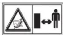
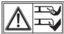
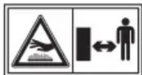
3.2 SAFETY SIGNS
The machine has various symbols on it (fig. 2). They are used to remind the operator of the behaviour to follow to use it with the necessary attention and caution. Meaning of symbols:

Warning: Read the instructions before operating the machine.
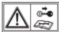
Warning: Disconnect the key and read the instructions before carrying out any maintenance or repair work.
Danger! Ejected objects: Do not operate without either the rear discharge guard or the grass catcher being in place. (for models with rear collection only)

Danger! Ejected objects: do not operate without side discharge chute in place. (for models with side discharge only)
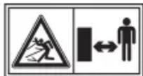
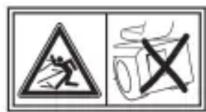
Danger! Ejected objects: Keep bystanders at a safe distance
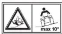
Danger! Machine rollover: Do not use this machine on slopes greater then 10^
Danger! Dismemberment: Make sure that children stay clear of the machine all the time when engine is running Cutting hazard. Cutting means in motion. Do not put hands or feet near or under the opening of the cutting means housing.
Warning! Keep away from hot surfaces.
When using the towing kit, do not exceed the recommended loads stated on the label and follow the safety instructions.
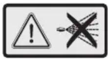
Warning! Never use pressure lances to wash the transmission system.
IMPORTANT Any damaged or illegible decals must be replaced. Order replacement decals from an authorised assistance centre.
3.3 IDENTIFICATION LABEL
The identification label holds the following data (fig. 1):
- Acoustic power level
- CE Conformity marking
- Year of manufacture
- Operating engine power and speed
- Machine model
- Type of machine
- Serial number
- Weight in kg
- Name and address of Manufacturer
- Type of transmission
- Article code
Write the identification data of the machine in the specific space on the label on the back of the cover page.
IMPORTANT Quote the information on the product identification label whenever you contact an authorized service workshop.
IMPORTANT The example of the Declaration of Conformity is provided on the last pages of the manual.
3.4 MAIN COMPONENTS
The machine is composed of a series of main components that have the following functions (fig.1):
A. Cutting-means assembly: this is the assembly comprising the casing that houses the rotating cutting means, and the cutting means.
B. Cutting means: these are what cut the grass; the fins at the ends help convey the cut grass towards the discharge chute.
C. Side discharge chute: a safety device to prevent objects drawn up by the cutting means from being hurled by the machine (for side discharge models only).
D. Discharge chute: this is the part connecting the cutting-means assembly to the grass catcher (for models with rear collector only).
E. Grass catcher: as well as collecting the grass cuttings, this is also a safety element that stops any objects drawn up by the cutting devices from being hurled away from the machine (for rear collection models only).
F. Rear discharge guard (available upon request): this can be fitted in place of the grass catcher and prevents objects from being drawn up by the cutting means and hurled away from the machine. (for rear collection models only).
G. Driving seat: this is where the machine operator sits. It has a sensor connected to safety devices for detecting the presence of the operator.
H. Battery: provides the energy for starting the engine. Its specifications and regulations for use are described in a specific manual.
I. Engine: this moves the cutting means and drives the wheels. Its specifications and regulations for use are described in a specific manual.
J. Front bumper: this protects the front section of the machine.
K. Steering wheel: turns the front wheels.
4. ASSEMBLY
The safety regulations to follow are described in chap. 2. Strictly comply with these instructions to avoid serious risks or hazards.
For storage and transport purposes, some components of the machine are not installed in the factory and have to be assembled after unpacking. Follow the instructions below.
Unpacking and completing the assembly should be done on a flat and stable surface, with enough space for machine handling and its packaging, always making use of suitable equipment. Do not use the machine until all the indications provided in the "ASSEMBLY" section have been carried out.
4.1 ASSEMBLY COMPONENTS
The packaging holds the components needed for assembly as listed in the table below:
| Description | |
| 1 | Steering wheel |
| 2 | Dashboard cover and steering wheel assembly parts |
| 3 | Driving seat |
| 4 | Battery |
| 5 Front bumpers |
| 6 Ant-chipping wheels |
| 7 Grass catcher with relative assembly screws and instructions (for models with rear collection only) |
| 8 Lower part of the rear plate, the grass catcher brackets and attachments necessary for completing and assembly (for rear collection models only) |
| 9 Side discharge chute (for models with side discharge only) |
| 10 Cutting-means assembly side reinforcements (for side discharge models only, if foreseen). |
| 11 Envelope containing: - the instruction manuals and documents - driving seat assembly screws - side discharge chute assembly fittings (for models with side discharge only) - the connection screws for the battery cables - 2 starter keys - 1 spare 10 A fuse |
4.1.1 Unpacking
- Cautiously open the packaging, paying attention not to lose components.
- Consult the documentation in the box, including these instructions.
- Remove all the unassembled parts from the box.
- Remove the machine from the packaging taking the following precautions: - move the cutting-means assembly to its maximum height (par. 5.10) to protect it against damage when the machine is lifted off the base pallet; - Lift the machine off the base pallet.
For hydrostatic drive models, move the rear drive release lever to the locked position (par. 5.13).
4.2 STEERING WHEEL ASSEMBLY
- Put the machine on a flat surface and straighten the front wheels.
- Mount the hub (fig. 3.A) on the shaft (fig. 3.B), making sure that the plug (fig. 3.C) is correctly fitted into the hub seat.
- Fit the dashboard cover (fig. 3.D) clicking the seven fasteners into place.
- Fit the steering wheel (fig. 3.E) onto the hub (fig. 3.A) with the spokes directed towards the seat.
5a. For type "I" steering wheel only - Fit the spacer (fig. 3.F) and fasten the
steering wheel in place using the screws supplied (fig. 3.G) in the indicated order.
5b. For type "II" steering wheel only - Fasten the steering wheel in place using the screws (fig. 3.F, 3.G) supplied, in the indicated order.
6. Fit the steering wheel cover (fig. 3.H) by clicking the fasteners into place.
4.3 SEAT ASSEMBLY
Fit the seat (fig. 4.A) onto the plate (fig. 4.B) using the screws (fig. 4.C).
4.4 MOUNTING AND CONNECTING THE BATTERY
The battery (fig. 5.A) is housed under the seat and secured by a spring (fig. 5.B).
- First connect the red wire (fig. 5.C) to the positive pole (+) and then the black wire (fig. 5.D) to the negative pole (-), using the screws supplied as shown.
- Apply silicone grease to the terminals and check that the protective cap for the red wire (fig. 5.E) is in place.
IMPORTANT Always fully charge the battery according to the instructions in the battery booklet.
IMPORTANT To prevent the safety device in the electronic circuit board from cutting in, never start the engine until the battery is fully charged!
4.5 MOUNTING THE REAR BUMPER
1a. For type "I" bumpers only - Mount the front bumper (fig. 6A) on the bottom of the frame (fig. 6.B) using the four screws (fig. 6.C).
1b. For type "II" bumpers only
- Fit the two brackets (fig. 6.A) and (fig. 6.B) to the bottom of the frame (fig. 6.C) following the direction of assembly indicated in the figure: R = right; L = left.
- fully tighten the screws (fig. 6.D).
- Attach the front bumper (fig. 6.E) to the brackets (fig. 6.A) and (fig. 6.B) using the screws (fig. 6.F) and nuts (fig. 6.G).
4.6 SIDE DISCHARGE CHUTE ASSEMBLY (FOR MODELS WITH SIDE DISCHARGE ONLY)
-
From the inside of the side discharge chute (fig. 7.A), fit the spring (fig. 7.B) by inserting the terminal (fig. 7.B.1) into the hole and turning it so that both the spring (fig. 7.B) and the terminal (fig. 7.B.2) are securely positioned in their seatings.
-
Position the side discharge chute (fig. 7.A) in line with the cutting-means assembly brackets (fig. 7.C). Using a screwdriver, turn the second terminal (fig. 7.B.2) of the spring (fig. 7.B) to bring it outside the side discharge chute.
- Fit the pin (fig. 7.D) in the holes on the brackets (fig. 7.C) and on the side discharge chute, so that it passes through the coils of the spring (fig. 7.B) and the drilled end comes out of the inner most bracket.
- Insert the cotter pin (fig. 7.E) in the pin (fig. 7.D) hole (fig. D.1) and rotate the pin until it is possible to bend the two ends (fig. 7.E.1) of the cotter pin, (with the aid of a pair of pliers), so it cannot slide out and cause the pin to fall out (fig. 7.D).
Check that the spring works correctly and keep the side discharge chute securely lowered. Make sure that the pin is fitted properly to prevent it from falling out accidentally.
IMPORTANT For models with optional side unloading: make sure that the side unloading guard (Fig. 13.A) is lowered and locked by the safety lever (Fig. 13.B).
IMPORTANT Before disassembling or servicing the deflector, always push the safety lever (Fig. 14.B) and lift the side unloading guard (Fig. 14.A) to allow disassembly.
NOTE To remove the deflector, perform assembly steps in reverse order.
4.7 MOUNTING THE CUTTING-MEANS ASSEMBLY SIDE REINFORCEMENTS (FOR SIDE DISCHARGE MODELS ONLY, IF FORESEEN).
Complete the mounting of the cutting-means assembly by fitting the side reinforcements on the cutting-means assembly profile using the screws supplied (fig. 8)
4.8 REAR PLATE ASSEMBLY AND COMPLETION (FOR REAR COLLECTION MODELS ONLY)
-
Assemble the two lower brackets (fig. 9.A) and (fig. 9.B), following the assembly direction as shown in the illustration, and fasten them with the screws (fig.9.C) and nuts (fig. 9.D), tightening them completely.
-
Remove the two screws (fig. 9.H), which will be used later.
- Assemble the lower part (fig. 9.E) of the rear plate and fasten it to the lower brackets with the screws (fig. 9.F) and bolts (fig. 9.G), without tightening them completely.
- Finish fastening the lower part (fig. 9.E) of the rear plate, completely tightening the two central screws (fig. 9.H) that you previously removed and the four upper screws (fig. 9.I)
- Fully tighten the two bottom nuts (fig. 9.G).
- Insert the lever (fig. 9.J) of the "grass catcher full" indicator into its seat (fig. 9.K) and push it down until you hear a click.
- Assemble the two grass catcher brackets (fig. 9.L) and (fig. 9.M), following the assembly direction as shown in the illustration, and fasten them with the screws (fig. 9.N) and snap washers (fig. 9.O), tightening them firmly.
5. CONTROLS
5.1 KEY IGNITION SWITCH
The key turns the machine and headlamps (if fitted) On and Off.
It has four different positions (fig. 10.A):

- Stop position. The machine turns off immediately.

- Headlights On position (if fitted); After turning the engine on, turn the lights on by turning the key to this position. To switch them off, turn the key to On.

- On position. All services are enabled..

- Start position. Switch on the starter motor to start the machine. If you release the key on start it will automatically return to On.
5.2 THROTTLE CONTROL
Regulates the engine's r.p.m.
There are two types of throttle control according to the engine type:
A. Type "I" with separate Choke command (Fig. 10.E + Fig. 10.E.1)
B. Type "II" (Fig. 10.E)
The positions indicated correspond to:

- Choke Command - Cold start. Used to turn on the engine when cold. The «CHoke» position enriches the mixture so it must only be used for the time necessary for cold starts.

- Maximum engine speed. To be used always when starting the machine, while it is On and during grass cutting operations.

- Minimum engine speed. Used when the machine is sufficiently warm during stationary periods of operation.
NOTE When moving from one area to another, put the lever in a position between «tortoise» and «hare».
This lever stops the machine from moving when it has been parked.
This lever has two positions (fig. 10.D), corresponding to:

- Brake disengaged. Press the pedal to disengage the parking brake (fig. 10.1). The lever returns to the brake disengaged position.

- Brake engaged. Press the pedal all the way down to engage the parking brake (fig. 10.1) and shift the lever to brake engaged position. When you take your foot off the pedal it will be blocked in the lowered position.
5.4 CLUTCH / BRAKE PEDAL (MECHANICAL DRIVE)
This pedal has a double function (fig. 10.1):

- during the first part of its travel it acts as a clutch, engaging and disengaging drive to the wheels.
- in the second part it works the brake on the rear wheels.
IMPORTANT Do not keep the pedal half way between clutch engagement or disengagement, as this can cause overheating and damage the transmission belt.
NOTE When the machine is in movement, keep your foot off the pedal.
5.5 SPEED CHANGE LEVER (MECHANICAL DRIVE)
This lever has seven positions (fig. 10.K):

- 5 forward gears Gear must only be engaged when the machine has stopped.


- Neutral «N»

- Reverse «R»
! Reverse must only be engaged when the machine has stopped.
To change gear, press the pedal halfway down (Fig. 10.1) and move the lever according to the indications on the label.
5.6 BRAKE PEDAL (HYDROSTATIC DRIVE)

This pedal works the brake on the rear wheels (fig. 10.l)
5.7 DRIVE PEDAL (HYDROSTATIC DRIVE)
This pedal engages drive in the wheels and controls the machine's forward and reverse speed (fig. 10.J):
- Forward drive gear. To insert the forward drive gear, press the front pedal with the tip of your foot. Increasing the pressure on the pedal progressively increases the speed of the machine.
-
Reverse gear. Reverse gear is engaged by pressing the rear pedal with your heel. Reverse must only be engaged when the machine has stopped.
-
Neutral position. The pedal automatically goes into neutral position when released.
NOTE If the drive pedal is used, whether forwards or for reverse, when the parking brake (fig. 10.D) is engaged, the engine stops.
5.8 HYDROSTATIC TRANSMISSION DISENGAGEMENT LEVER (HYDROSTATIC TRANSMISSION)
This lever has two positions, as shown on the plate (fig. 10.L):

- Drive engaged : for all uses, when moving and during cutting.

- Drive disengaged : this makes it much easier to move the machine by hand, with the engine turned off.
IMPORTANT To avoid damaging the transmission unit, this operation must be carried out only when the engine has stopped with the pedal (fig. 10.J) at neutral position.
5.9 CUTTING MEANS ENGAGE AND DISENGAGE FUNCTIONS
The mushroom switch allows you to engage the cutting means using an electromagnetic clutch (fig. 10.B):

- Cutting means engaged. Mushroom switch pulled
-
Cutting means disengaged. Mushroom switch engaged.
-
On disengaging the cutting means, a brake is simultaneously activated which stops their rotation within a few seconds.
NOTE If you engage the cutting means without taking the necessary safety precautions, the engine shuts down and cannot be restarted (see par. 6.2.2)
5.10 REVERSE GEAR CUTTING CONSENT BUTTON

By pressing and holding this button (fig. 10.F), it is possible to switch to reverse gear with the cutting means engaged without causing the engine to stop.
5.11 CUTTING HEIGHT ADJUSTER LEVER
Use this lever to raise and lower the cutting-means assembly to one of the 7 different cutting heights (fig. 10.G).

The seven positions for this lever, shown as «1» to «7» on the label, correspond to various cutting heights between 3 and 8 cm.

To go from one position to another, move the lever sideways and put it back in one of the stop notches.
5.12 ACOUSTIC ALARM INDICATOR LIGHT AND DEVICE (FOR REAR COLLECTION MODELS ONLY)
- This light (fig. 10.C) comes on when the key (fig. 10.A) is in the "ON" position and stays on while the machine is running.
- When it flashes, it means that it is not ready to be started (see par. 6.2.2).
- The sound warning signals that the grass catcher is full (see par. 6.5.5).
5.13 GRASS CATCHER TIPPING LEVER (IF FORESEEN, FOR REAR COLLECTION MODELS ONLY)
This pull-out lever tips and empties the grass catcher. This means less work for the operator (fig. 10.H).
6. USING THE MACHINE
The safety regulations to follow are described in chap. 2. Strictly comply with these instructions to avoid serious risks or hazards.
6.1 PREPARATION
Before starting to mow, it is necessary to carry out several checks and operations to ensure you can work efficiently and in maximum safety.
6.1.1 Filling with oil and fuel
IMPORTANT The machine is supplied without engine oil or fuel.
Before using the machine check for fuel and the oil level (par. 7.2, par. 7.3). For refuelling and oil top-up methods and precautionsent follow the instructions given in (par. 7.2, par. 7.3) and in the engine handbook.
6.1.2 Seat adjustment
To change the seat position, loosen the four fixing bolts (fig. 11.A) and slide it along the slots. Once you have found the right position, tighten the four screws (fig. 11.A) thoroughly.
6.1.3 Tyre pressure
Having the right tyre pressure is the main condition for ensuring that the cutting-means assembly is horizontal and mows evenly.
- Unscrew the valve caps
- Connect a compressed air line with a gauge to the valves (fig. 12)
- Adjust the pressure according to the values indicated in the "Technical Data" chart.
6.1.4 Preparing the machine before starting work
NOTE This machine can be used to mow lawns in a number of different ways; before starting work, prepare the machine based on how the lawn is to be mowed.
a. Prepare the machine for side cutting and discharge of the grass onto the floor (for models with side discharge only)
- Always make sure that the spring inside the deflector (Fig. 13.A) and the safety lever (Fig. 13.B, 14.B) operate correctly, holding it firmly in the lowered position.
b. Preparation for grass cutting and collection in the grass catcher (for rear collection models only)
- Fasten the grass catcher (fig. 15.A) onto the supports (fig. 15.B) and centre it up
with the rear plate. Centring is ensured by using the right bracket as lateral support.
- Make sure that the lower pipe of the grass catcher opening is attached to the pawl (fig. 15.C).
c. Prepare the machine for rear cutting and discharge of the grass onto the floor (for models with rear collection only)
- If you decide to work without the grass catcher, a rear discharge guard kit (fig. 16; chap. 15.5) is available upon request. This has to be attached to the rear plate as indicated in the instructions.
d. Preparation for mowing and mulching of grass
- If you decide to mow the grass, mulching it and leaving it on the grass, a "mulching" kit is available upon request (chap. 15.1). This has to be attached to the rear plate as indicated in the instructions.
6.1.5 Positioning the anti-scalp wheels
The anti-chipping wheels are used to reduce the risk of tearing up sections of lawn, which can occur when the edge of the cutting-means assembly drags over irregular ground. Position the wheels as indicated (par. 7.4).
6.2 SAFETY CHECKS
Run the following safety checks and check that the results correspond to those outlined on the tables.
Always carry out the safety checks before use.
6.2.1 General safety check
| Object Result | |
| Battery No damage to the casing,cover or terminals | |
| Rear discharge guard,grass catcher | Good condition. No damage. Properly installed. |
| Side discharge guard, suction grid | Good condition. No damage. Properly installed. |
| Fuel lines and connections. | No leaks. |
| Electrical cables. All insulati0n intact.No mechanical damage. | |
| Oil lines No leaks. | No damage. |
| Drive the machine forwards and backwards, shift to neutral / release the drive pedal (par. 5.5; par. 5.7) | The machine slows down and stops |
| Press the brake pedal (par. 5.4; par. 5.6) | The machine stops |
| Test driving No abnormal vibrations. No abnormal sound | |
| Safety devices Proceed as indicated in par. 6.2.2 | |
6.2.2 Control of safety devices
The safety devices work in two ways:
A. they prevent the engine from starting if all the safety requirements have not been met;
B. by stopping the engine if even just one of the safety requirements is lacking.
| Action Result | |
| 1. gear in "neutral"; 2. cutting means disengaged; 3. operator seated. | The engine starts |
| the operator leaves his seat The engine stops | |
| the grass catcher is lifted or the rear discharge guard removed without disengaging the cutting means (for rear collection models only) | The engine stops |
| the parking brake is engaged without disengaging the cutting means | The engine stops |
| the speed change is activated or the drive pedal with the parking brake engaged | The engine stops |
| the reverse gear is engaged with the cutting means engaged, without pressing the consent button (par. 5.9) | The engine stops |
If any of the results fails to match the indications provided in the tables, do not use the machine! Contact a service centre to have it checked and repaired if necessary.
IMPORTANT Always bear in mind that the safety devices prevent the engine from starting if safety requirements have not been met. In these cases, once the start consent has been reinstated, the ignition key (fig. 10.A) must first be turned back to Of before the engine can be restarted.
6.3 USING ON SLOPES
Comply with the limits indicated in the "Technical Data" Tables ad in "fig. 19" regardless of the mowing direction.
Remember there is no such thing as a "safe" slope. Driving on grass slopes requires particular care. To prevent overturning or loss of control over the machine:
- Never mow across the face of the slope. Lawns on a slope have to be mowed moving up and down and never across them. When changing direction, take great care that the wheels facing the slope do not hit any obstacles (such as stones, branches, roots, etc.) that may cause the machine to slide sideways, tip over or make you lose control.
- Do not stop or start suddenly when going up or downhill;
- Shift to drive gear very gently paying particular attention to prevent the machine from tipping up.
- Reduce speed:
- before changing direction and during tight turns
- before facing a slope, particularly downhill
- Never switch to reverse gear to decrease speed when going downhill: this could cause loss of control of the machine, especially on slippery ground.
-
Always engage the parking brake before leaving the machine at a standstill and unattended.
-
For models with mechanical drive only Never ride the machine on slopes in neutral or with the clutch out! Always shift into a low gear before leaving the machine at a standstill and unattended.
- For models with hydrostatic drive only: Drive down slopes with your foot off the drive pedal to use the braking effect of the hydrostatic transmission when the transmission is not engaged.
6.4 STARTUP
- Open the fuel tap (fig. 20.A) (if provided).
- Sit in the operator's position.
- Put the drive into neutral («N») (par. 5.5; par. 5.7).
- Disengage the cutting means (par. 5.8).
- Engage the parking brake (par. 5.3).
- Shift the throttle control to maximum "hare" speed position (par. 5.2).
-
If cold starting: engage the choke (par. 5.2 / par. 5.2.1)
-
Insert the ignition key and turn to On to make electrical contact, then turn it to Start to start the engine.
- Release the ignition key once the engine has started.
- If cold starting: as soon as the engine ticks over regularly:
10a. Disengage the choke (par. 5.2 type "II"), shift the throttle control to maximum "hare" speed position.
10b. Disengage the choke (par. 5.2, type "I").
NOTE Using the choke when the engine is already warm can foul the spark plugs and cause the engine to run erratically.
- When the engine has started, shift the throttle control to the minimum «tortoise» speed position.
NOTE If there are engine starting problems, do not insist as you can risk running the battery flat and flooding the engine. Turn the key to the Off position, wait for a few seconds and then repeat the operation. If the malfunction persists, refer to the engine manual and chapter «14» in this manual.
6.5 OPERATION
6.5.1 Forward gear and riding without mowing
When moving the machine:
disengage the cutting means (par. 5.8);
- bring the cutting-means assembly to the highest position (position «7»);
- shift the throttle control to a point midway between the «tortoise» and «hare» speed positions.
-
For models with mechanical drive only:
-
Press the pedal all the way down (par. 5.4) and shift the gear lever to 1st gear (par. 5.5).
- Hold the pedal down (fig. 10.1) then disengage the parking brake (par. 5.3).
- Slowly release the pedal which will turn from «brake» to «clutch» mode, thus operating the rear wheels (par. 5.4).
The pedal has to be released gradually, as a sudden engagement may cause the vehicle to tip over and the driver to lose control.
- Gradually reach the desired speed using the throttle and gear lever. To change gear, press the clutch halfway down (par. 5.4; par. 5.5).
IMPORTANT Gear must be engaged when the machine has stopped.
-
For models with hydrostatic drive only:
-
Disengage the parking brake and release the brake pedal (par. 5.6).
- Press the drive pedal (par. 5.7) in the "forward drive" direction and reach the required speed by gradually increasing pressure on the pedal and working the throttle.
Drive can only be engaged following the procedure illustrated (par. 5.7 to prevent sudden engagement which may cause the vehicle to tip over and the driver to lose control, especially on slopes.
6.5.2 Braking
First reduce the machine's speed by reducing the engine's r.p.m., and then press the brake pedal (par. 5.4; par. 5.6) to slow down the machine until it stops.
For models with hydrostatic drive only:
The machine already slows down considerably by just releasing the drive pedal (par. 5.7)
6.5.3 Reverse gear
IMPORTANT Reverse must be engaged when the machine has stopped.
For models with mechanical drive only:
- Press the pedal (par. 5.4) until the machine comes to a stop;
- Shift the gear lever to "R" reverse (par. 5.5).
- Gradually release the pedal to engage the clutch and then begin moving in reverse.
For models with hydrostatic drive only:
- Press the pedal (par. 5.6) until the machine comes to a stop;
- start reversing by pressing the drive pedal in the "R" direction (par. 5.7).
6.5.4 Grass cutting
To operate with the machine proceed as described below:
- shift the throttle to the maximum speed position ("hare"); this position is always used when using the machine;
- bring the cutting-means assembly to the highest position;
- engage the cutting means (par. 5.8) only on grass lawns; avoid engaging them on stony ground or when the grass is very high;
- regulate the forward speed and the cutting height (par. 5.10) considering the conditions of the lawn (the height, density and dampness of the grass).
- start moving forwards on the grass very slowly and with utmost caution, as already described;
IMPORTANT To proceed in reverse gear with the cutting means engaged, it is necessary to press and hold the consent button (par. 5.9) so as not to cause the engine to stop.
Lower the speed whenever you note a drop in engine speed, since a forward speed that is too fast compared to the amount of grass being cut will never mow the grass well.
Disengage the cutting means and move the cutting-means assembly to the highest position:
- When moving between work areas
- When driving on grass free surfaces
- Every time it is necessary to overcome an obstacle.
6.5.5 Suggestions for maintaining a nice lawn
- To keep a lawn green and soft with a good appearance, it should be cut regularly. A lawn can be composed of different types of grass. If the lawn is cut frequently, grass and roots grow more vigorously, forming
a solid grassy bed. If the lawn is cut is less frequently, higher grass and weeds start growing (clover and daisies, etc.).
2. It is always better to cut the grass when dry.
3. The cutting means must be in good condition and well sharpened so that the grass is cut straight without a ragged edge that leads to yellowing at the ends.
4. The engine must run at full speed, both to ensure a sharp cut of the grass and to get the necessary thrust to push the cuttings through the collector channel.
5. The frequency of mowing should be in relation to the rate of growth of the grass, which should not be left to grow too much between one cut and the next.
6. During hot and dry periods, the grass should be cut a little higher to prevent the ground from drying out.
7. The best height of the grass on a well-kept lawn is approx. 4-5 cm. and with one mowing, you do not need to remove more than a third of the total height. If the grass is very tall, it should be cut twice in a twenty-four hour period. The first time with the cutting means at maximum cutting height, possibly reducing the cutting width and the second cut at the height desired (fig. 21).
8. The appearance of the lawn will improve if you alternate the cutting in both directions (fig. 22).
9. If the discharge chute tends to get blocked with grass, you should reduce the forward speed as it may be too high for the condition of the grass. If the problem persists, the probable causes are either badly sharpened cutting means or deformed fins.
10. Be very careful when mowing near bushes or kerbs as these could distort the horizontal position of the cutting-means assembly and damage its edge as well as the cutting means.
6.5.6 Emptying the grass catcher (for rear collection models only)
NOTE The emptying of the grass catcher can only be done with the cutting means disengaged, otherwise the engine stops.
- Do not let the grass catcher become too full as this may block the collection channel.
- When the grass catcher is full you will hear a warning sound:
- disengage the cutting means (par. 5.8) and the audible signal will stop
- shift the throttle control to minimum "tortoise" speed position (par.
-
stop moving forward and switch to neutral (par. 5.5; par. 5.7);
-
engage the parking brake;
- stop the engine;
- pull out the lever (fig. 23.A - if fitted) or grasp the rear handle (fig. 23.A1) and tip up the grass catcher to empty it;
- close up the grass catcher so that it hooks onto the pawl (fig. 23.B).
6.5.7 Cleaning the discharge chute (for rear collection models only)
- Cutting very tall or wet grass, particularly at excessively high speed, can clog up the discharge chute. If it clogs, follow the instructions provided in chap. 7.4.2.
6.5.8 Mowing completed
When mowing has been completed:
- disengage the cutting means;
- decrease the engine's r.p.m.
- drive back with the cutting-means assembly in its highest position:
6.6 STOP
To stop the machine:
- shift the throttle lever to minimum "tortoise" speed position
To avoid backfire, leave the throttle in the minimum "tortoise" speed position for 20 seconds before switching off the engine.
- switch off the engine by turning the ignition key to Off;
- with the engine turned off, close the fuel tap (fig. 24.A) (if provided).
- remove the key from the ignition
IMPORTANT To keep the battery charged, do not leave the ignition key in the «on» or «headlights on» position when the engine is not running.
The engine may be very warm immediately after it is shut off. Do not touch the exhaust or adjacent parts. This can cause burn injuries.
6.7 AFTER OPERATION
- Allow the engine to cool before storing in an enclosed space.
- Clean (par. 7.4).
- Lower the cutting-means assembly, shift to neutral, engage the parking brake, turn off the engine and remove the
ignition key (checking that all moving parts are completely stationary):
- whenever the machine is left unattended, the operator dismounts from the driving seat, or parks the machine;
7. ROUTINE MAINTENANCE
7.1 GENERAL INFORMATION
The safety regulations to follow are described in chap. 2. Strictly comply with these instructions to avoid serious risks or hazards.
Before conducting any inspections, cleaning or maintenance/adjustment interventions on the machine:
disengage the cutting means;
- shift into neutral;
- engage the parking brake;
stop the engine;
- remove the key, (never leave the keys in the ignition or within reach of children or unauthorised persons);
make sure that all moving parts have come to a complete stop;
- read the relevant instructions;
- Use suitable clothing, protective gloves and goggles
- The frequency and types of maintenance are summarised in the "Maintenance Table". The table will help you maintain your machine's safety and performance. It lists the main maintenance tasks and how often they need to be performed. Carry out the relevant task as soon as it is scheduled to be performed.
- The use of non-genuine and/or incorrectly assembled spare parts and attachments could adversely affect machine operation and safety. The manufacturer shall decline all liability in the event of injuries or damages caused by such parts.
- Genuine spare parts are supplied by authorized assistance workshops and dealers.
7.2 REFUELLING / EMPTYING THE FUEL TANK
NOTE The type of fuel to use is given in the engine manual.
IMPORTANT The machine is delivered to the client without fuel. Follow all the instructions in the engine manual.
7.2.1 Refuelling
To refuel:
- Unscrew the tank closure cap and remove it (fig. 25).
- Insert the funnel (fig. 25).
- Refuel being careful not to completely fill the tank.
- Remove the funnel.
- Close the fuel cap securely after refuelling and clean away any spills.
IMPORTANT Do not drip petrol onto
the plastic parts to avoid ruining them.
In the event of accidental leaks, rinse immediately with water. The warranty does not cover for damage to plastic parts of the bodywork or the engine caused by petrol.
7.2.2 Emptying the fuel tank
NOTE Fuel is perishable and should not remain in the tank for more than 30 days. Empty the fuel tank before storing the machine for long periods of time (chap. 9).
Allow the engine to cool before emptying the fuel tank.
- Place the machine on a flat surface, in the open air.
- Place a suitable container under the drain tube (fig. 27.A).
- Disconnect the tube (fig. 27.A) installed on the fuel filter inlet (fig. 27.B).
- Open the fuel tap (if provided)
- Collect the fuel in a suitable container.
- Reconnect the tube (fig. 27.A) making sure you position the clamp properly (fig. 27.C).
- Close the fuel tap (if provided).
The next time the machine is used, check that there are no fuel leaks from the tubes, fuel stopcock or carburettor.
7.3 CHECK, TOP UP, DRAINING OF ENGINE OIL
NOTE The type of oil to use is given in the engine manual.
IMPORTANT The machine is delivered to the client without engine oil.
IMPORTANT Follow all the instructions in the engine manual.
7.3.1 Check/top-up
Always check the oil level before use.
- Check the oil level: according to the instructions in the engine manual, this must be between the MIN and MAX marks on the dipstick (fig. 26).
Do not overfill as this could cause the engine to overheat. If the oil level exceeds the "MAX" mark, drain until the correct level is achieved.
7.3.2 Draining
The oil may be very hot if removed just after the engine has been switched off. Consequently allow the engine to cool down for a few minutes before proceeding to drain off the oil.
Replace the engine oil according to the frequency indicated in the engine instruction manual.
Proceed as follows:
-
Type "I":
-
Place the machine on a flat surface.
- Place a suitable container under the extension tube (fig. 28.A).
- Hold the extension tube (fig. 28.A) firmly in place and unscrew the drain plug (fig. 28.B).
- Collect the oil in a suitable vessel.
- Replace the drain plug (fig. 28.B) making sure that the gasket is in the right position (fig. 28.C).
- Fully tighten holding the extension tube firmly in place (fig. 28.A).
-
Clean up any spills.
-
Type "II":
-
Unscrew the topping up cap (fig. 28.A).
- Fit the tube (fig. 28.B) onto the syringe (fig. 28.C) and insert it as far as possible into the hole.
-
Using the syringe (fig. 28.C), suck up all the engine oil, bearing in mind that you need to repeat this operation a few times before all the oil is removed.
-
Type "III":
-
Place the machine on a flat surface.
- Place a suitable container under the extension tube (fig. 28.A).
- Press the cotter (fig. 28.B)
- Release the extension tube from the support by moving it downwards;
-
Bend the extension tube and drain the oil into a suitable container.
-
Refit the extension tube (fig. 28.A) on the support (fig. 28.C) before topping up the oil.
- Clean up any spills.
IMPORTANT Hand the spent oil over to a disposal facility in accordance with local provisions.
7.4 ANTI-CHIPPING WHEELS
The different heights of the wheels allow you to maintain a safe distance "H" between the cutting-means assembly and the ground (fig. 17.A, fig. 18.A). Adjust the position of the anti-chipping wheels according to how irregular the ground is.
This should always be performed on both wheels, positioning them at the same height WITH THE ENGINE OFF AND CUTTING MEANS DISENGAGED.
a. for models with side discharge only
To change the position:
-
unscrew and remove the screw (fig. 17.B)
-
reposition the wheel (fig. 17.A) with the spacer (fig. 17.C) inside the hole at the desired distance
-
fully tighten the screw (fig.17.B) onto the nut (fig. 17.D).
b. for models with rear collection only
To change the position:
- unscrew the nut (fig. 18.B) and extract the pin (fig.18.C).
- reposition the wheel (fig. 18.A) in the desired position
- reassemble the pin (fig. 18.C), making sure the pin (fig. 18.C) head is facing toward the inside of the machine
- then tighten the nut completely (fig. 18.B).
7.5 CLEANING
Clean thoroughly following the instructions below every time it is used.
7.5.1 Cleaning the machine
- Clean the outside of the machine washing the plastic parts of the bodywork with a damp sponge using water and detergent, taking care not to wet the engine, the electrical parts or the electronic circuit board located under the dashboard.
- To reduce fire hazards, keep the engine, silencer, battery compartment and petrol storage area free of grass, leaves, or excessive grease.
IMPORTANT Never use hose-nozzles or harsh detergents for cleaning the body and engine!
IMPORTANT Do not wash the transmission system when it is hot. Never use pressure lances to wash the transmission system.
7.5.2 Cleaning the discharge chute (for rear collection models only)
If the discharge chute is clogged:
- remove the grass catcher or the rear discharge guard;
- remove the grass cuttings; you can reach them from the channel discharge opening.
7.5.3 Cleaning the grass catcher (for rear collection models only)
- Empty the grass catcher
- Shake it to remove grass cuttings and soil residue
- Replace the grass catcher and clean the interior of the cutting-means assembly (par. 7.4.4-a), now remove the grass catcher, empty and rinse it, then place it where it can dry quickly.
7.5.4 Cleaning the cutting-means assembly
Clean the cutting-means assembly thoroughly to remove any grass remains or debris.
Keep people or animals away from the surrounding area when cleaning the cutting-means assembly.
a. Cleaning the interiors
When washing the inside of the cutting-means assembly and the discharge chute, the machine must be on firm ground with:
- the grass catcher or the rear discharge guard mounted in place (for rear collection models only)
- the side discharge chute mounted (for models with side discharge only);
- the operator seated;
- the cutting-means assembly in position «1»;
- the engine running
- the transmission in neutral
-
the cutting means engaged
-
Connect a water hose to each of the pipe fittings (fig. 29.A; fig. 30.A) one at a time and run water through each one for a few minutes, with the cutting means moving.
-
follow the instructions in the battery manual;
IMPORTANT In order not to compromise the efficiency of the electromagnetic clutch: - do not let the clutch come into contact with oil; - do not spray pressurised water directly on the clutch unit; - do not clean the clutch with petrol.
b. Cleaning the exterior
Do not let debris and dried grass accumulate in the upper part of the cutting-means assembly in order to maintain maximum machine efficiency and safety levels.
To clean the upper part of the cutting-means assembly:
- lower the cutting-means assembly completely (position «1»);
- blow a jet of compressed air through the right and left guard openings (fig. 29; fig. 30).
7.6 BATTERY
To ensure long life to the battery it is essential to keep it carefully maintained. The machine battery must always be charged:
- before using the machine for the first time after purchase;
- before leaving the machine disused for a long period (over 30 days) (par. 9);
- before starting up the machine after a prolonged period of inactivity.
Carefully read and observe the battery recharging instructions in the booklet provided with the battery. Failure in following the procedure or in charging the battery could permanently damage the battery elements. A flat battery must be recharged as soon as possible.
IMPORTANT Recharging must be done using a battery charger at constant voltage. Other recharging systems can irreversibly damage the battery.
- The machine comes with a connector (fig. 31.A) for recharging; this is connected to the corresponding connector for the special maintenance battery-charger supplied (if included) or available on request (par. 15.2).
IMPORTANT This connector must only be used for connection to the maintenance battery-charger indicated by the Manufacturer. For its use: - follow the instructions given in the relative instructions manual;
7.7 NUTS AND BOLTS
- Keep all nuts, bolts and screws tight to be sure the equipment is in safe working condition.
8. EXTRAORDINARY MAINTENANCE
8.1 SAFETY RECOMMENDATIONS
You must go to a specialized Service Centre or contact your Dealer if the following are malfunctioning: -the brake -the cutting means engage and disengage functions -switching the drive to forward or reverse gears.
8.2 CUTTING-MEANS ASSEMBLY / CUTTING MEANS
8.2.1 Aligning the cutting-means assembly
The cutting-means assembly should be properly adjusted to obtain an evenly mown lawn (fig. 32). If mowing is uneven, check the tyre pressure (par. 6.1.3). If this is not sufficient to achieve an even cut, please contact your Dealer to adjust the alignment of the cutting-means assembly.
8.2.2 Cutting means
A badly sharpened cutting means pulls at the grass and causes the lawn to turn yellow.
All work on the cutting means (disassembly, sharpening, balancing, repairing, reassembly and/or replacing) are demanding jobs that require special skills as well as special tools. For safety reasons, these jobs are best carried out at a Specialised Centre.
Make sure damaged, misshapen or worn cutting means are replaced as a whole unit, together with its own screws in place to preserve balance.
IMPORTANT Cutting means should be replaced in pairs, especially when there are marked differences in wear.
IMPORTANT Always use original cutting means bearing the code indicated in the "Technical Data".
Given product evolution, the cutting means listed in the "Technical Data" table may be replaced in time with others having similar interchangeable and operating safety features.
8.3 REPLACING OF FRONT / REAR WHEELS
8.3.1 Preparation
IMPORTANT Use a suitable lifting device, for example a scissor jack.
Before changing the wheels it is necessary to complete some preliminary operations:
- Remove all attachments.
- Position the machine on a solid and even surface that guarantees stability of the machine.
- Engage the parking brake;
- Stop the engine;
- Remove the key from the ignition;
- Position the jack in the lifting position near the wheel to be changed (par. 8.3.2; par. 8.3.3).
- Check that the jack is perfectly perpendicular to the ground.
8.3.2 Choice and positioning of the jack on the rear wheels
Position some wooden wedges (fig. 33.A) to the wheel base (fig. 33.B) to the side of the wheel to be changed (fig. 33.C).
For models with rear collection:
- The maximum possible jack height when closed is 110 ~mm . (fig. 33).
- Position the jack under the rear plate (fig. 34.A) at 180mm from the side edge.
For side discharge models:
- The maximum possible jack height when closed is 110 ~mm . (fig. 35).
- Position the jack under the rear axle, in the point indicated in the diagram (fig. 36.A).
NOTE In this position the jack allows you to only raise the wheel to be changed.
8.3.3 Choice and positioning of the jack on the front wheels
- Position some wooden wedges (fig. 37.A) to the wheel base (fig. 37.B) behind the wheel to be changed (fig. 37.C).
- The maximum possible jack height when closed is 110mm
- Position a square 10 × 10 cm wooden wedge (fig. 38.B) on the jack (fig. 38.A).
NOTE The wooden wedge prevents damage to the front axle.
- Raise the jack so that the wedge rests against the chassis and structural parts (fig. 38.C).
NOTE During this phase use your hand to keep the wedge balanced correctly on the jack.
NOTE In this position the jack allows you to raise the entire front axle.
8.3.4 Changing the wheel
IMPORTANT Make certain the machine remains still and stable during the lifting process. If you notice anything out of the ordinary, lower the jack immediately, check and resolve any problems and lift the machine again.
- Remove the cover (fig. 39.A).
- Raise it enough to extract the wheel easily.
- Using a screwdriver, remove the snap ring (fig. 39.B) and the shoulder washer (fig. 39.C).
- Remove the wheel to be changed.
- Coat the axle (fig. 39.D) with grease.
- Mount the spare wheel.
- Carefully replace the shoulder washer and snap ring.
IMPORTANT Check that the two rear wheels are the same height (fig. 40.A) and that the difference between the external diameters of the two wheels (fig. 40.B) is no greater than 8 - 10 ~mm . On the contrary, to avoid uneven mowing, the cutting-means assembly must be aligned by an authorised service centre.
8.3.5 Repairing or changing tyres
The tyres are "Tubeless" and so all punctures must be repaired by a tyre repairer following the procedures required for this kind of tyre.
8.4 ELECTRONIC CIRCUIT BOARD
The electronic circuit board is a component fitted below the dashboard which manages all machine safety devices.
8.4.1 Electronic circuit board protection device (for rear collection models only)
- The electronic circuit board is located below the dashboard and fitted with a self-setting protection which breaks the circuit if there is a fault or short circuit on the electrical system (chap. 14).
8.4.2 Electronic circuit board protection fuse (for side discharge models only)
- The electronic circuit board is located below the dashboard and fitted with a fuse which breaks the circuit if there is a fault or short circuit on the electrical system (chap. 14).
8.5 REPLACING A FUSE
The machine is fitted with fuses (fig. 41.A) with different capacities and functions. Specifically:
-
10 A fuse = protects the main and power circuits of the electronic circuit board. When it blows, the machine stops and the dashboard light switches off (for rear discharge models only (par. 5.11)
-
25 A fuse = protects the battery recharge circuit. When it blows, the battery gradually runs down and the machine will have problems starting.
The fuse capacity is indicated on the fuse.
IMPORTANT A blown fuse must always be replaced by one of the same type and ampere rating, and never with one of another rating.
If you are unable to understand why it has blown , contact Your Dealer.
8.6 REPLACING BULBS
8.6.1 Type "l" - Incandescent light bulbs
- The bulbs (18W) have a bayonet fitting and are installed in the bulb holder which can be taken out by turning it anti-clockwise with pliers (fig. 42).
8.6.2 Type "II" - LED light bulbs
- Loosen the lock nut (fig. 42.A) and remove the connector (fig.42.B). Remove the LED illuminator (fig. 42.C), secured by screws (fig. 42.D).
8.7 REAR AXLE
- This is a sealed single unit that does not require maintenance. It is permanently lubricated and its lubricant does not need changing or topping up.
9. STORING THE MACHINE
When you intend to put your machine away for more than 30 days:
- Wait for the engine to cool
- Disconnect the battery cables and store it in a cool and dry place.
- Empty the fuel tank (par. 7.2.2) and follow all the instructions in the engine manual.
- Clean the machine thoroughly.
- Check the machine for any damage. If necessary, contact the authorised assistance centre.
- Store the machine:
with the cutting-means assembly lowered
-in a dry place - protected from inclement weather
- and covered with a sheet where possible (par. 15.4)
- in a place where children cannot get to it
- making sure that keys or tools used for maintenance are removed.
Before starting to use the machine again:
- check that there are no fuel leaks from the tubes, fuel stopcock or carburettor.
- prepare the machine as described in chapter "6. Using the machine".
10. HANDLING AND TRANSPORTATION
- When handling the machine, always: - disengage the cutting means; - bring the cutting-means assembly to the highest position; - stop the engine;
- When transporting the machine on a vehicle or trailer, always: - use an access ramp of suitable strength, width and length; - load the machine with the engine switched off, with the key removed from the ignition, without a driver and push by an adequate number of people; - close the fuel tap (if provided); - lower the cutting-means assembly; - engage the parking brake; - position it so that it can not cause a hazard for anybody; - fasten firmly to the means of transport ropes or chains to prevent it from tipping over causing damage and fuel leaks.
11. ASSISTANCE AND REPAIRS
This manual provides all the necessary information to run the machine and for correct basic maintenance operations which can be performed by the user. Any regulations and maintenance operations not described herein must be carried out by your Dealer or Authorized Service Centre, which have the necessary knowledge and equipment to ensure that the work is carried out correctly, maintaining the correct degree of safety and the original operating conditions of the machine. Any operations performed in unauthorized centres or by unqualified persons will totally invalidate the Warranty and all obligations and responsibilities of the Manufacturer.
-
Only authorized service workshops can carry out guaranteed repairs and maintenance.
-
The authorized service workshops only use genuine spare parts. Genuine spare parts and attachments have been designed specifically for machines.
- Non-original parts and attachments are not approved; use of non-original spare parts and attachments will jeopardize the safety of the machine and relieve the Manufacturer from all obligations or liabilities.
- It is advisable to send your machine once a year to an authorized service workshop for servicing, assistance and safety device inspection.
12. WARRANTY COVERAGE
The warranty covers all material and manufacturing defects. The user must follow all the instructions provided in the accompanying documentation. The warranty does not cover damages caused by:
- Failure to become familiar with the documentation accompanying the machine.
- Carelessness.
- Incorrect or prohibited use or assembly.
- Use of non-genuine spare parts.
- Use of attachments not supplied or approved by the manufacturer.
The warranty does not cover: - Normal wear and tear of consumables, such as drive belts, headlights, wheels, blades, safety bolts and wires.
Normal wear and tear. - Engines. Engines are covered by the warranty provided by the relative manufacturer in compliance with the specified terms and conditions.
The purchaser is protected by his own national legislation. The purchaser's rights envisaged by the national laws in his own country are not in any way restricted by this warranty.
13. MAINTENANCE TABLE
The boxes at the side are for you to mark the date or number of working hours at which the intervention was made.
| Operation Frequency | (hours) | Completed (Date or Hours) Notes | |||||
| MACHINE | |||||||
| Safety checks/check controls | Before each use | par. 6.2 | |||||
| Tyre pressure check | Before each use | par. 6.1.3 | |||||
| Assembly/Checking of outlet guards | Before each use | par. 6.1.4 | |||||
| General cleaning and inspection | After each use | par. 7.4 | |||||
| Checking for any damage to the machine. If necessary, contact the authorised assistance centre. | After each use | - | |||||
| Battery power reserve | Before storage | par. 7.5 | |||||
| Complete bolt and screw check | 25 | ||||||
| Cutting means positioning and sharpening check | 25 *** | ||||||
| Transmission belt check | 25 *** | ||||||
| Cutting means control belt check | 25 *** | ||||||
| Brake regulation and check | 25 *** | ||||||
| Drive regulation and check | 25 *** | ||||||
| Cutting means gear and brake check | 25 *** | ||||||
| General lubrication | 25 **** | ||||||
| Replacing cutting means | 100 *** | ||||||
| Replacing the transmission belt | - ** / *** | ||||||
| Replacing the cutting means control belt | - ** / *** | ||||||
| ENGINE | |||||||
| Checking/topping up fuel level Before | each use | par 7.2 | |||||
| Check/top-up engine oil Before | each use | par 7.3 | |||||
| Replacement of the engine oil ... * | |||||||
| Air filter cleaning and check ... * | |||||||
| Air filter replacement ... * | |||||||
| Fuel filter check ... * | |||||||
| Fuel filter replacement | ... * | ||||||
| Spark plug points cleaning and check | ... * | ||||||
| Replace the spark plug | ... * | ||||||
- See the engine manual for the full list and frequency
At the first signs of any malfunction, contact your Dealer immediately
The operation must be carried out by your Dealer or a specialized Service Centre
** General lubrication of all joints should also be carried out whenever
the machine is to be left unused for a long period.
14. PROBLEM IDENTIFICATION
| PROBLEM | PROBABLE CAUSE | REMEDY |
| 1. With the key turned to «ON», the light stays off (for rear collection models only) | The safety device of the electronic circuit board has cut in due to: | Turn the ignition key to «STOP» position and look for the cause of the problem: |
| badly connected battery check the connections (par. 4.4) | ||
| battery terminals crossed check the connections (par. 4.4). | ||
| flat battery recharge the battery (par. 7.5) | ||
| fuse blown replace fuse (10 A) (par. 8.5). | ||
| wet circuit board dry using luke warm air | ||
| 2. With the key turned to «START» the light flashes and the starter motor does not run (for rear collection models only) | starting conditions have not been met check (par. 6.2.2) | |
| 3. With the key turned to «START» the light is on but the starter motor does not run (for rear collection models only) | insufficiently charged battery recharge the battery (par. 7.5) | |
| malfunction on the starter relay contact your Dealer |
If problems persist after having performed the above operations, contact your dealer.
| PROBLEM PROB | ABLE CAUSE REMEDY | |
| 4. With the key turned to “START” the starter motor does not run (for side discharge models only) | Turn the ignition key to “STOP” position and look for the cause of the problem: | |
| starting conditions have not been met c | check that all starting conditions are met (par. 6.2.2) | |
| badly connected battery check the connc | ctions (par. 4.4) | |
| battery terminals crossed check the cor | nctions (par. 4.4) | |
| flat battery recharge the battery (par. 7.5) | ||
| fuse blown replace fuse (10 A) (par. 8.5) | ||
| wet circuit board dry using luke warm air | ||
| malfunction on the starter relay contact | your Dealer | |
| 5. With the key on “START” the starter motor runs but the engine does not start | insufficiently charged battery recharge t | the battery (par. 7.5) |
| faulty fuel supply check the level in the tank | tank (par. 7.2.1) | |
| open the fuel stopcock (if foreseen) (par. 6.4) | ||
| check the fuel filter | ||
| faulty ignition check that spark plug cap | is securely fitted | |
| check that the electrodes are clean and have the correct gap | ||
| 6. Starting is difficult or the engine runs erratically | carburation problems clean or replace the air filter | |
| 7. Weak engine performance during cutting | forward speed too high in relation to cutting height | reduce the forward speed and/or raise the cutting height (par. 6.5.4) |
| 8. The engine shuts down whilst working | the safety devices have cut in | check that all starting conditions are met (par. 6.2.2) |
| blown fuse due to a short circuit or electrical system faults (for side discharge models only) | The cause of the fault should be ascertained and dealt with to avoid reactivating the protection device | |
| Replace the fuse (10 A) (par. 8.5). Contact your Dealer if such interruptions continue | ||
| 9. The engine stops whilst operating and the indicator light switches off (for rear collection models only) | The safety device of the electronic circuit board has cut in due to: | Turn the ignition key to “STOP”, wait for a couple of seconds to allow the circuit to reset automatically and: |
| battery terminals crossed | check the connections (par. 4.4) | |
| faults in the battery charging regulator | check the battery connections (par. 4.4) | |
| check the battery is fitted | ||
| short circuit | contact your Dealer | |
| 10. The cutting means do not engage or do not stop promptly when they are disengaged | problems with engagement mechanism | contact your Dealer |
If problems persist after having performed the above operations, contact your dealer.
| PROBLEM PROBABLE CAUSE REMEDY | ||
| 11. Uneven mowing and insufficient collection (for rear collection models only) | cutting-means assembly is not parallel to the ground | check the tyre pressure (par. 6.1.3) |
| reinstate the alignment of the cutting-means assembly in relation to the ground (par. 8.2.1) | ||
| inefficient cutting means | contact your Dealer | |
| forward speed too high compared to height of grass | reduce the forward speed and/or raise the cutting-means assembly (par. 6.5.4) | |
| wait for the grass to dry | ||
| collector channel is blocked | remove the grass catcher and empty the discharge chute (par. 7.4.2) | |
| 12. Uneven mowing for side (discharge models only) | cutting-means assembly is not parallel to the ground | check the tyre pressure (par. 6.1.3) |
| reinstate the alignment of the cutting-means assembly in relation to the ground (par. 8.2.1) | ||
| inefficient cutting means | contact your Dealer | |
| 13. Unusual vibrations while working | cutting-means assembly is full of grass | clean the cutting-means assembly (par. 7.4.4) |
| the cutting means are unbalanced or loose | contact your Dealer | |
| loose bolts and screws | check and tighten all the engine and frame bolts | |
| 14. Uncertain or ineffective braking | the brake is not adjusted correctly | contact your Dealer |
| 15. Erratic forward movement, poor drive when going uphill or if the machine has a tendency to rear up | problems with the belt or the engagement device | contact your Dealer |
| 16. With the engine running, the machine does not move when the drive pedal is pressed (hydrostatic transmission models) | release lever in the gear disengagement position | return it to the gear engaged position (par. 5.13) |
| 17. The machine starts to vibrate abnormally and/ or has hit an object | damaged or loose parts | stop the machine and remove the ignition key |
| inspect for damage | ||
| check for and tighten any loose parts | ||
| have all checks, repair work and replacements carried out by a specialized Centre only. | ||
If problems persist after having performed the above operations, contact your dealer.
15. ATTACHMENTS
15.1 "MULCHING" KIT
It finely chops the grass cuttings and leaves them on the lawn (fig. 43.A1; fig 43.A2).
15.2 MAINTENANCE BATTERY CHARGER
This keeps the battery in good working order when the machine is in storage, guaranteeing an optimum level of charge and longer battery life (fig. 43.B).
15.3 TOWING KIT
To tow a small trailer (fig. 43.C).
15.4 CANVAS COVER
Protects the machine from dust when not in use (fig. 43.D)
15.5 REAR DISCHARGE GUARD KIT
Used instead of the grass catcher when the cuttings are not collected (fig.43.E). (For rear discharge models only).
15.6 18" SNOW CHAINS
These improve front wheel adherence on snow-covered sections of road and allow the snow shovel equipment to be used (fig. 43.F).
15.7 18" MUD / SNOW WHEELS
These improve drive performance on snow and mud.
15.8 TRAILER
For transporting tools and other objects within the allowed load limits (fig. 43.H).
15.9 SPRINKLER
To sprinkle salt or fertilisers (fig. 43.I).
15.10 GRASS ROLLER
To make the soil compact after seeding or to flatten the grass (fig. 43.J).
15.11 SNOW BLADE
Shovels and accumulates removed snow to the side (fig. 43.K).
15.12 LEAF AND GRASS COLLECTOR
For the collection of leaves and grass on lawn surfaces (fig. 43.L).
INDICE
- INFORMACION GENERAL 2
- NORMAS DE SEGURIDAD 2
- CONOCER LA MAQUINA 5
15.1 KIT PARA "MULCHING"
8.1 RECOMMANDATIONS POUR LA SÉCURITÉ
8.5 REMPLACEMENT D'UN FUSIBLE
10. MANUTENTION ET TRANSPORT
2.5 BESCHERMING VAN DE OMGEVING
B. Type "II" (Afb. 10.E)
7.2.2 Lediging reservoir
7.7 MOEREN EN SCHROEVEN VOOR BEVESTIGING
8.6.1 Type "I" - Gloeilampen
15.1 KIT VOOR "MULCHING"
- EKSTRAORDIN/AERT VEDLIKEHOLD......17
8.1 Sikkerhetsforskrifter 17
8.2 Klippeenhet/klippeinnretninger 18
8.3 Utskifting av for-/bakhjulene 18
8.4Kretskort 19
8.5 Bytte av en sikring 19
8.6 Bytte av lyspaerer 19
8.7 Bakaksling 19
- LAGRING 19
10.FLYTTING OG TRANSPORT 20
11. SERVICE OG REPARASJONER 20
12. HVA SOM DEKKES AV GARANTIEN......20
13. VEDLIKEHOLDSTABELL 21
14.FEILsOKING 22
15.TILBEHØR. 24
15.1 Mulching-sett 24
15.2 Batterilader 24
15.3 Sett med tilhengerfeste 24
15.4 Presenning 24
15.5 Sett med vern for utkast bak 24
15.6 Snokjettinger 18" 24
15.7 Gjørme-/snøhjul 18" 24
15.8 Tilhenger 24
15.9 Spreder 24
15.10 Gressrulle 24
15.11 Snoplog 24
15.12 Blad- og gressoppsamler 24
1. GENERELT
1.1 HVORDAN LESE BRUKSANVISNINGEN
2.4 VEDLIKEHOLD OG LAGRING
3. BLI KJENT MED MASKINEN
3.1 BESKRIVELSE AV MASKINEN OG TILSIKTET BRUK
5.10 KNAPP FOR KLIPPING I REVERS
8.6.1 Type "I" - Glodelamper
- Lyspaerene (18 W) har bajonettsokkel og kan tas ut ved Å vri den mot klokken med en tang (fig. 42).
8.6.2 Type "II" - LED-paerer
- Løsne ringen (fig. 42.A) og ta ut koblingsstykket (fig. 42.B). Demoner LED-lampen (fig. 42.C) som er festet med skruene (fig. 42.D).
8.7 BAKAKSLING
15.5 SETT MED VERN FOR UTKAST BAK
2.2 CZYNNOSCI WSTEPNE
6.1 CZYNNOSCI WSTEPNE
IMPORTANT NAO Iave a
15.1 KIT PARA "MULCHING"
Tritura bemina relva cortada e a deixa no relativado (fig. 43.A1; fig. 43.A2).
CpeDCTBa HndnBnDyaJbHoJ 3aunTbI (CN3)
HaJeHbTe nOxOJyO OJy, npOHyo pa6OyU o6yBb Ha HeCKoJIb3aIeN pODoWBe N dInHHbIe 6pOKn. He 3aynckaiTe MaunHy bocnKOM nIn B OTKpbITbIX caHaJInx. HaJeHbTe HayuHNKn dJa 3aunTbI opraHOB cLyxa.
HeHaedeBaIe 7apfo, XaIaTbI, KOJIbe, 6paCJIeTbI, pa3BeBaUOyUoC ODeJdy, a TaKHe ODeJdy CO UHypKamN IraIcTyKn, a TaKHe LIObIe BnCraYne NIIu ShIpOKne AkCEccCyapbl, KOTOpBIE MOrTy 3acTpRb B MaUSHHe NII IN B ppeDMetax N MaTePnaJalax, HaxODaUHXsC Ha pa6Ouem MeCTe.
-ДолжныМ образимсоберпдлHHьBEBOLOсbl.
Pa6oun yuactok / MaunHa
BHHMaTeIbHO OCMOTpHrE pa6OuH yuaCTOK uYbepHTe BCE, YTO MoKHeT 6bITb Bbl6poWeHO MaunHoN, IIn6o NOBpeDHTb peKyuUee npncnOc6JIeHne/ BpaAouJHecr OprAHbI(KamHn, BETKn, pOBOLOky, KocTn T.D.).
ДВИГАТЕЛВИЧТРЕнногС cropanя: TOnJIHBO

ONACHOCTb! TOnJIHBOJeRKO BOCNJaMaHeYeTc.
XpaHnTe TOnJIbBO B CneuHaIbHbIX KaHnCTpax, OMOJIoRIpOBaHHbIX IJa DaHHoIy eJI, B 6e3OpanChOM MeCTe, BdJIH OT NCTOCHIKOB TeJIa I OTKpbITOrO PJIaMeHI.
OuHuaTe KaHnCTpbI mMeTo XpaHeHn6eH3nHa OTOCTaTKOB TpaBbl, IINCTbeB IN3JIuShKOB CMa3Kn.
He ocTaBnIe KaHnCTpbI B npEdeJax DoCraemocTn DeTei.
He Kypnte BO Bpem 3a npabkn nIINdoJIbKn TOnJIbNa, a TaKHe BOO6e npn OcbpaueHn C TOnJIbOM.
3aIINBaIte TOnJIInBO Yepe3 BOpOHky, TOJIbKO NOI OTKpbITbIM He6OM.
-Избегаитевдьханя napOB TOnJIbBa.
He do6abJTe TOnJIbO u He cHMaIte npo6ky 6aka, KOrda DBrIgatelb pa60taet nIu KOrda OH rOp8yni.
MeJenHOn OTKpoIte np6ky 6aKa, YTO6bl NOCTepeHHO C6pocHTb BHyTpENHeE DaBJIeHne;
He npn6nnkaIte nIamr K 3aIpaBOUHOMy OTBepCTNUO 6aHa, YTO6bI npOBepNTb eRO cODePJKHMoe.
B cIyuae pa3IbA TOJIbA He 3aynckaIte DnIraTeIb, y6epHTe MaunHy C MeCTa pa3JIbA ToJIbA I npIMNtE Mepbl Ipo npEynpExJdeHIO BO3rOpAHnI Do TEX Iop, noka TOnJIbO He IcnapITcI n erO napbl He paccetoTcI.
- HemeДелену уберп Te Bce следы ТОПЛИВа, КOTOPоЕnpOLIOСь Ha MaшИнHy Или На 3eMЛЮ.
- Bcerda Bo3BpaaIte Ha MeCTO nПLOTHO 3aKpyuNbAaiTe npo6Kn 6aKa n KaHnCTpbI C TOnJIbVOM.
He 3anyckaIte MaunHy B MeCTe 3anpaBKn; 3anyck DnurataTeJr Heo6xOndmo
OCyUeCTBJIaTb Ha paCCToHn He MeHee, Yem 3 MeTp aOT MeCTa 3aPpAKn TOnJIINBOM.
- I36eaiTe KOHTaKTa TOnJIbBa C ODeJdoi n, B cIyuae ee 3aIrpIzHeHnIy, nepeOJeHbTecb nepeD 3aNyCKOM DBNrAteJIa.
2.3 BO BPEMRA PABOTbl
Pa6ouy uactok
He BkIIOuayTe DnIRaTeJIb B 3aKpbITOM npocTpaHCTBe, rJe MOKeT CKONITbcr OAnchbYrApHbI ra3. 3aynck DoJKeH npOn3BOIDtBCr Ha yLIuce HINB XopoOIO npOBeTPBaEMOM MeCTe. He 3a6bIbaIte O TOM, YTO BBIXLOHNbIe Ra3bl DnIRaTeJI TOKCNHbI.
-BoBpeMaJyckMaunHbI HeHaPpaBnTe rLyuHTeNbI, CLeIOBaTeJIbHO,BbIXLONHe Ra3bl Ha IerKOBocIIaMeHouUneCeMaTePnaJIbI.
He nCnoIb3yInTe MaunHy BO B3pbIBOOnaCHO
cpeDe, N6bln3OCTn OT rOpUoynx HndKOCTeN,
ra3a nn PbIi. 3JeKtpnueCKne KOHTaKTbI
HmexaHnueCKoe TpeHne MOryt
CReHepnPOBaTb NCKpbl, KOTOpBle MOryt
PnivBeCTn K BO3rOpAHIO PbIi NNn NapOB.
- Pa6oTaTb TToIbKO npn dHeBHom cBeTe nI npn XopoWeM NcKycCTBeHHOM OcBeUeHIn, B ycIOBnX XopoWeN BvIMOCTn.
Ha pa6ooyem yuactke He doJIHKHO 6bIb B3pOcIbIX IIODei, DeTei HJNBOThbIX. Heo6xOdmo, YTO6bl DpyroB 3pOcblIy eJIOBeK CMOTpeI 3a DeTbMn.
- I36eRaTe pa6Otbl Ha MOKpoi TpaBe, PODdoKdEm HIn ecIn 6JIH3NTcra rPo3a, OCO6eHHo ecIn BO3MOxHbI MOJHn.
- 06paaTe ocObe BHNMaHne Ha HepOBHOCTn NOpBbl (KoUKN, KaHaBbl), Ha yKIOH, Ha cKpbITbIe ONaCHOCTN I NaIIuYe BO3MOXHbIX IppeTCTBNI, KOToPbIE MOryT OrpaHnUHTb BNIMOCtB.
- Cобл�дайе осторожность, работая ряdomсобрывами, канавами и берaramи вODEмов. Машина может onрокинтуся, сли пою ИЗ Кoleс пешидт череши Край пл eсни Край обвалится.
Co6JIIOdaIte OCTOpOJHOCbHa HaHJIOHHbIX yuaCTkax, Ie CLeIyEt pa6oTaTb OC6eHHO BHNMaTeIbHO BO N36eJHae ONpOKnDbIbAHN IIN NToEpN KOHTpOJI NaM MaunHO. HnKe NepeuNCJeHbI OCHOBHbI PnUHHbI NToEpN KOHTpOJI:
-HeIOCTaTOUHoe cUeIJIeHne MeKdY KOJecAMN IN NOBepXHOCTbIO
- CnIshKOM BbICOKa CHOPoCTb
- HeDocTaToUHoe TopMOnKeHne
- Maшина He COOTBETCTBYETeJIH NcPOnJIb3OBAHnI
-He3HaHne, KaK pa3IuHbIe NOBepxHOCTN BJIaHT Ha NOBeHHeMaShnHbI
- HenpaBnIbHna 3KcIlyaTauaB KaueCTBe Traya.
Ppabnla nobedeHn BO BpeMa pa6oTbI
BoBpemyynpaBneHnMaunHOn n pa6oTbI He OTBLeKaTbcN IdoJIHHbIM 6pb3OM cKOHcHTnpOBA TbCnHa pa6Ote.
-БудьTe OCTOPOJHbI npi DBnHexHn3aHnIM XODOM nIN Ha3ad.Прn DBnHexHn3aHnIM XODOM CMOTpHTe Ha3ad Do INBO BVPeMЯ DBnHexHnY, YTObI y6eINTbcB BOTCYTCTBn INpeNATCTBn.
-Прибукровke Гузовил
при Использовани Тяжелого
оборudовеня 6удte Внимаелы:
-Для Крениня 6укрньх
Тяг ИспользуйтЕ ТOLTКО
праздаЗнayechные ДЯ 3TOGO мecта;
-He поворачи军建е руь peзko.
Будte Внимаелы при
MaHEВрах 3аднIM XODOM;
-УстановITE потивовсыни
Гузkin Ha Kolеса, eclin B
pyKOBODCTBE NO ЭСплuyaразци
pekomehdnyetc nX Использованe.
-БудъTe ocToPoJHbI, KOrda nCNoJIb3YeTcKa KOHTeHepДЯ c6opa TpaBbl NnI IOnOJIHNTelbHoe O6OpyDoBaHne, KOTOpoe MOKeT HapUHt b YCTOuHBOCTb MaunHbI, B YaactHOCTn, NOd YKLOHOM.
Bcerda depknte pykn n Hn Ha pacctoHn ot peKyuIero npncno6JeHn KaK BO BpeM 3ayncKa, TaK n BO BpeM pa60tbl Ha MaunHe.
BhImaHne:peKyuSni3JIeMeHT npoDoJxHaET BpaAsTbC8B TeueHne HeCKOJIbKnX ceKyHd NocJe erO BbIKIuOeHnN IIN NocLe BbIKIuOeHnN DBNrAteJI.
-Будъte ocSTOPOxHbI npn pa6oTe c peKyuUIMN y3IaMn, BkJIuOuaOUsMn 60Jee oHOro peKyuUeTo npncnOco6JeHn, nCKoJIbKy bpaUeHne OndHoro peKyuUeTo npncnOco6JeHnma MoKeT Bbl3BaTb bpaUeHne dpyrnx.
- Bcerda DepeKHTecb Ha pacCToHn OT OTBepCTnДЯ Bbl6poca.
He npikacaiTecb K qactam DnirataJIa, KOtOpbIe HarpBaIOTcR BO BpemraPabOtbl. Pnck OxKorOB.
-Чтоби He co3daBaTb рнck BO3HnKHOBEHnЯ
noJapa, He OCTabIaIe HeNoDBrNHyU
MaShInHy C BKNIOyeHHbIM DBNrAteIeM
Ha yUCArThe C BbICOKO TpaBOi.
Bclyae noIOMOK nIaBapn BO Bpemra60bI He3aMeIINTeIbHO BbIKIOCHITbDBrataJIb Iy6paTb MauHHy, YTO6bI OHa HHeNecla eue 6OJIbUIM yUeP6; ecNI pOn3OWeJI HeCuaCTHbI ClyuA N OpeaTOp IIN TpeTbI INuCa POnUYuIN TpaBMbl, He3aMeIINTeIbHO npInrAB MepbI NO NOMOUs NocTpaDaBWM,
HAn6OJee NODXODJIeNBE KOHNKeTHoH CNTyaUaUN, N O6paTHTbC8 B MeDnUHcKoe UypeJdEHNHe IJN Heo6XoDMOrO JleUeHn. TuaTeNbHO ydaJInte MaTePnAJI, KOTOpBI MOKeT HaHeCTn YUep6 HIn TpaBMJI LIOJAM IN JINBOTHbIM, KOTOpbIE MOrYte ERO He 3aMeTNTb.
OrpaHnueHnB npImMeHnHn
- HnKoRda He noIb3OBAtbc MaunHOc NOBpeJdeHhbIMN, OTCyTCTBYUOuIMN IIN He npaBnIbHO paCNoLOJKeHHbIMN 3aHTbIMN npCnOC6JIeHnAIMN (KOHTeHepdJa c6opAp TpaBbl, 3aNTa 6OKOBOro Bbl6poca, 3aNTa 3aDHeRo Bbl6poca).
He nCnoJb3yIte MaunHy,ecnIdoOpHnTeIbHoeObOpUdoBaHne/ HnCTpyMeHT He yCTaHOBJIeHbIB npeducMOTpeHHbIX MeCTax.
He OTKIIOUaTe, He BbIKIIOUaTe, He CHIMaIte n He pa36npaIte HMeIOUneC8 3aHTbIe yCTPOHCTBa/MNKPOBbIKIIOuAten.
He noDbepraTe MaunHy Upe3MepeHbIn Harpy3kam N He nCNoIb3yInTe MaJeHbkyo MaunHy DJIa BblOJIHeHn TAnKeJIoPa60TbI; NcNoIb3OBaHne NoDxOJaUeMauHHbI CHINKaET pNCK I NOBbIaAET KaueCTBO pa60TbI.
MaunHa He npedHa3NaeHa IJnIncNoJIb3OBaHnHa Ha DOpOraX O6UeToIolb3OBaHn. Ee nCnoJIb3OBaHnE (coJIaCHO npabNlAm DOpOxHOrO DBNKeHn) pa3peSeHo TOIbKO Ha YacTHoI TeppITOpHn, OTDeJIeHNOr OT DOpOxHOrO DBNKeHn.
2.4 TEXHnueECKOE OBCJyHKINBAHNE, XPAHEHNE
PergyIapHoeTexHnueeKoe 06cIyJHbAHne I npaBnIbHOe XpaHeHne YBJIOTc3aIIOrOM 6e3OpacHOCTMaunHbI N NOdEprKaHnE ee 3KcIIpyataUOHHbIX KaueCTB.
TexHnuechoe 06cIyHHBaHne
- Hn B Koem Cnyae He nCNoJb3OBAtB MaunHy C n3HOCNBuIMNCra NnI NOBpeJDeHHbIMN YacTAMn. NOBpeJDeHHbIE Nn3HOCNBuNEcR DeTaJIi BCerDa Heo6XoDIMO 3aMeHЯrB, OHN He nOJaEHaT peMOHTy.
- Д�� поедOTВрашениOnаСоCTN BOЗгораннpergулрHo yДОCTOBерЯITecь B OTCYTCTBи yTeueK Macla n/NЛN TOnJIbA.
- Bo Времанади Maшинbl Heобхдимо\ pa6otatb Oyehb BHMaTeIbHO BO n36eJkaHne\ PonadaHЯпальсев B lceIb MeJdY\ Движушмся ржушmПрисnocoblenem\ И HeNoDВиЖнblIMn y3JIaMn Maшинbl.
3HaueHn yPoBna N Bn6paun, yKa3aHHbIe B HacToaem pyKOBoDCTBe, ABLIAOTcMaKcImaJIbHbIM pa6OuHMN
3HaueHnMaMnMaunHbI. HcnoJb3OBaHne
He6balaHncroBaHHoro peKyuapeTo 3JeMeHTa,
CInuHKOM BbICOKaY CKOPoCTb, OTCyTCTBVe
TexHnueCKOrO 06cLyJKNBaHnry CyUeCTBeHNO
BnIAOT Ha yPoBeHb 5yMa n BV6paQnIO.
CLeIDoBaTeJIbHO, Heo6xOdIMo PpINrA
PpoFnlaKTnueckNe Mepbl Dnla YcTpAHeHnra
BO3MOJHoro yUepe6a, BbI3BaHHoro BbICOKm
yPoBhem 5yMa n BV6paQNoHHbIMn HaRpy3KaMn;
BbINOJIHrTB 06cLyJKNBaHnne MaunHbI,
HaDeBaTb IpOTNBOwUMhble HayShnKn,
DeJaTb NpepeBbI BO BpeMra6oTbI.
XpaHHeHne
He cTaBbTe MaunHy C ToPJIbOM B 6aKe B NOMEuEne, rDe HcnapeHn TOnJIbBa MOrTy BCTyNTb B KOHTaKT C PJIaMeHem, NCKpO HIN NCTOCHNKOM CNJbHOro TeTla.
-ДяСнжehня рисka noЖара He OCTaBЯТь KOHTeHepbI C OTXODaMn B NOMEseHIn.
2.5 OXPAHA OKPYHJAIOUCEI CPEDbI
OxpaHa OkpyKaIOUe CpeBdI DOJIHHa
YBIArTBcA CyIecTBeHHbIM I NepBOOuePeHbIM
ACNEKTOM PnI POJIb3OBaHm MaUNHOi,
BO 6JlArO YeIOBueeCKOrO O6IeCTBa I
OKpyKaIOUe CpeBdI, B KOTOpOI Mbl JKNBEm.
- CṭapaǐTecb He 6ecnokoHTb OkpykaHoux.
Исpoь3уйTe Maшину Tólbko B pa3ymHoE
Врем (He paHO yTpOM H He NO3dHO BeuepOM,
KOrda Bbl MOnKeTe NOMEuATb OkpyKaIoUmM). - CtrpOro co6IIOdaIte MeCTHbIe HOpMbI NO yTININ3aUHN yNApKOBHN, MaceI, TOnJIbBa, fIIbTPOB, NOBpeJDeEHbIX YAcTeH NII INIO6bIX 3JeMeENTOB CO 3NaHTeJIbHbIM BInrHHe Ha OKpyJaIOUyO CpeDy; 3TN OTXoDbI He DOJIKNbI BbIbPaCbIBaTbcR C 6bITOBblM MycOpOM, a CO6npaTbcR OTdEJIbHO I nepeDaBaTbcR B CneuAInbHbIe CEHTpbI C6opAOTXODOB, BBINOJIHraIOUne IN X Nepepa60TKy.
CTpOro co6IIOdaTb DeiCTByIOUHe Ha MeCTHOM yPOBHe npaBnla IO BbIBO3y OTXoIOB. - После завершени срoka слжбы Maшины He ВьIBLEвайт ee C sbITOBbIM MycopOM, a образиТecь B ueHTp c6Opa OTXODOB B COOTBeTCTBnC DeiCTByIOUIM MeCTHbIM 3aKOHODaTeJIbCTBOM.
3. O3HAKOMJIENHE C MAUNHOI
3.1 ONHCAHNE MAUHHbI IN IPEyCMOTPEHHOE IPNMEHEHNE
Данна Maшина яВ liaетс самоюну ra3OHOKOCHIO C cndeHbem OnepaTopa.
BAJHHO HenaJIeKaIe ee IcNoJIb3OBaHne
MaunHbBJeCyET3aCObyUTpaTy CnblI rapaHTnN CHnMaetC N3rOToBnTeTnB CIO OTBeTCTBeHHoCTb, BO3JaRaHa NOpJb3OBaTeTn OTBeTCTBeHHoCTb 3a N3DePckn B CJIyae NOPuN mMyueCTBa, POnLyueHn TpaBM nLI NaHeCeHnY uSepe6a TpeTbM IIncaM.
3.1.3 Tn noIb3ObaTeJa
3.4 OCHOBHbIE KOMNOHEHTbl
Maunha COCTOHT n3 CLeDyUoX OCHOHBIX COCTaBbIX YacteN, KOTOpBe BbINOJIHJOT CLeDyUOuHe FyHKcNn (pnc.1):
A. Pechyшny 3eJ: B 3OT y3eJ BXOJYKOPnyc, B KOTOpB' 3aHIOUeHbI BpauaOuIeCRA peKyuIe npncno6oJIeHnI, n HEnocpeCTBeHHOp eKyuIe npncno6oJIeHnI.
B. PeЖушип рисспособленья:эTO
эЛем entbl,празднзнayчehньie ДЯ
Кошени Травы;pacnoLOжeHHьe Ha
Концpeбра способctByOT habравленью
Скоченho TравыВkaHaNВ bblбрoca.
C. Боновий Хелов Дя Вьбраза: 3aшитhoe yctpoiCTBO, npedotBpaaiouoe
Bb6poc CO6paHHbIX peKHyUIMN
PnncnoC6JIeHNAm NpEaMeTOB Ha
6OJIbIoo paCCToHHe (TOLbKO JIy
MoJeIe C 6OKOB pa3rpy3KoJ).
D. KaHaJI BbIbPoCa: 3TO COeДИHITeJIbHbI JIeMeHT MeJdU peKHyUcIM y3IOM I KOHTeHepOM dJIa C6Opa TpaBbI(TOJIbKO dJIa MoDEJIeC 3aIHNM C6OpOM)
E. HonteHep dIa c6opa TpaBbI: Kpome c6opa cKoUeHHoT PpaBbl OH BbIIOJIHaET TaKHe IpeOxpaHnteJIbHyIO fYHKuIIO, NocKOBky IpeDToBpaUaAet BbIbPoC c6opaHbIX peKyuImn IprcNOC6JIeHnAMn IpeDMeTOB Ha 6OJbUoe pacCTOHN (ToJbKO dIy MoJeIe C 3aDNIM c6OpOM)
F. 3aunta 3adHero Bb6poca (noTpe6oBaHIO): yCTaHaBnBaETcR
NO Tpe6oBaHIO): yCTaHaBnBaETCR
BMecTO KOHTeHepa dIra c6oparpaBbl,
PpeDToBpaAaet Bb6poc c6paHHbIX
peKyuIMN pnpCnOco6JIeHnMn
PpeDMeTOB Ha 6oJbWoepacCToHnE.
(TolbHO JIy MoJeIe C 3aHnM C6OpOM)
G. CndeHbe BOINTeJIa: 3TO pa6ooye MeCTO ONEpaTopa, OHO OCHaUeHO DaTChKOM, PACNo3HaUoUm eRO pNcCyTCTBHe, KOtOpbI HEO6XODIM DJIa pa6oTbI PpeDOxpaHInTeJIbHbIX yCTPOJCTB.
H.Батaper:обеспechиВаETэлкгоэнргюДЯЗануСаДВИгATEЛ;eeхарКТериCTиИnpaВиlaэКсПуаТAUOПИСАНБIВOTДeЛьHOMpyKOBODCTBE.
I.ДВиразелб:обеспунваet КаддИжени
рекуши писносоьлен, тak и
привовд кoleс; ergхарктеристник
и правILA зкрлuyaразиOnОпсаны
В OTДЕЛьНOM руковоростve.
J. Переднибампек: обсячимbaertaшиту передни части машинь.
K. Pylb: ynpablaet nobopoTOM nepednIX KOleC.
4. MOHTAHK
I npabnla 6e3oNaChOCTn npBedeHb I B rI.2.Ctporo co6JIOdaIte yHa3aHna BO n36eHaHne cepbe3HbIX pNcKOB n OnaChOCTn.
B cB3n co cnlaHnpOBaHneM n TpaHCnopTnPOBKO HeKOTOpbIE COCTaBHbI YeactN MaunHbI He Co6npaIoTcH HEnocpeDCTBeHHo Ha 3aBoDe, INx Heo6XoHMo CO6paTb NocLe ydaJIeHHaYnaKOBOuHOrMaTePnAJa, COrJaLacHO CLeyUOuMM Yka3aHnM.
PacnaKOBHa n 3aBepseHne MOtHa
dOJIHHbI BbINOJHrTbCn Ha TBepDoN H
POBHOIOBepxHOCTn, rJe DOcTaTOUHO MeCTa
dIy IpeMeueHnMaunHbI N ee yNaKOBHN,
Heo6xOJMo Bcerga NOJb3OBA Tbbcra COOTBeTCTByUOzHMn HNCTpyMeHTaMn. Ipeed NcIIOJb3OBAHHeMaunHbI Heo6xOJMo BbINOJHnTb BCE yHa3aHnY, n3IoJeHHbIe B pa3dJe "MOHTAH".
BAHHO UTo6bI He IOnyCTnTb Cpa6aTbIBaHHa3aUHTbI 3JIeKTOHON IIaTbI, HN B KOEM Cnyae He 3aNyCKaIte DnRaTeIb Do 3aBepWeHnI PONHO3apJKn!
4.5 MOHTAЖ ПЕДHEGO BAMNEPA
1a. Tollebno dJa 6ampepa "I"- YctanobnTe nepeDnH 6ampep (pnc. 6.A) Ha HnHHIOU qacTb pambl (pnc. 6.B) pnI NOMOUI YeTbIPex BnHTOB (pnc. 6.C).
1b. Tolbno Ддя бampepa Tnpa "II"
- YctahOBInTe DBe OOnOpbI (pnc. 6.A) n (pnc. 6.B)Ha HnKHHIOuacTb paMbI (pnc. 6.C), co6JIouJa HaPpaBHeHne MOHTaJka, NOKa3aHHoe Ha pncyHKe: R= cnpaba; L= cIeBa.
- 3aTaNHTe BnHTbI (pnc. 6.D) do ynpa.
3.ПикpenTeпердньбampep (pnc.6.E) к орам (pnc.6.A) n (pnc.6.B) ри пomoци вHTOB (pnc.6.F) ngaek (pnc.6.G).
4.6 MOHTAN BOHOBOTO JEJOBAДЛЯ BblbPOCA (TOJIbHOДЛЯ MOpEJIeN C BoHOBOY PA3rpy3KoI)
- CBHyTpeHHeN CTOpONb 60KOBOrO JKeIIO6a DIA BbIbPoCa (pnc.7.A) yCTaHOBnTB npJHKnHy (pnc.7.B), BCTaBnB KOHeU (pnc.7.B.1) B OTBepCTne H NOBepHyTb ee TaK, YTO6bI npJHKnHa (pnc.7.B) n KOHeU (pnc.7.B.2) 6blnn PLOTHO yCTaHOBJIeHbI B COOTBeTCTByIOuXrHE3dax.
- YCTaHOBtB 6OKOBJ KJIeIOB DJIY BbIbPOCa (pnc.7.A) B COOTBeTcTBnC OONOpAMN (pnc. 7.C) Ha peJHyIeM y3JIe N pRi NOMOUI OTBepTKI NOBepHyTb BTOPOJ KOHeU (pnc. 7.B.2) npJxHbI (pnc.7.B) TaK, UTO6bl OH OKa3aJIc8 bI C HApJXHNoI CTOpOHbI 6OKOBOrO JKeIOBa dJIY BbIbPOCa.
- BCTaBtB cTepeHb (pnc. 7.D) B OTBepCTnA onop (pnc. 7.C) n 60KoBOrO JHeIo6a DIA BbIbPOcTaT, qTO6bl OH npoxoJIN BHyTpN BHTKO BpyJHHbl (pnc. 7.B) do NOJIHOro BbIXOJa nepΦOpnpOBaHHORO KOHca N3 BHyTpEnHei ONOpbl.
- BCTaBnTb 7E) B OTBepCTne (pnc. D.1) cTePxHn (pnc. 7.D) n NobepHytb CTePxeH TaK, TTO6bl DaBa KOHca (pnc. 7.E.1) 7tNfTa MoJHo 6bl 6bl 3aHyTb (pni NOMOuN KIeUe) TaHm O6pa30M, TTO6bl OH He MOr 6bl BBICKOHTb N BbInyCTnTb CTePxeHb HapuyKy (pnc. 7.D).
YIOCTOBepbTecb, YTO npyHnHa
fYHKUHOHPyeT npaBnIbHo, HAdEHHO
yDcEPHBa8 6oHOBOJ HeNo6 JIa
BbIbOpca B Hn3HOM NIOJOHeHN, I
yTO cTePHeHb XopoOo BCTaBNeH n
He MoHET ClyuayHO BbICHOHTb.
BAHHO B MoTeJAX C BO3MOJHOCtBIO 6OHOBON BbIpy3HN: yBeJNTecB, YTO 3aUHTa 6OKOBON Bblpy3HN (pnc. 13.A) onuSeHa n 3a6LKnpoBaHa npedoxpaHnteJbHbIM pbIyarOM (pnc. 13.B).
BAHHO Ipeed cHrTHeM HnI TeXo6CnyKnBaHnEM DeΦJIeKTopa HeO6xOJMo HaKaTb Ha IpeDoxpaHHTeJIbHbI pbIur (pnc. 14.B) nIOJHrTb3aUHTy 60KOBov BbIRpy3KN (pnc. 14.A), YTO6blI03BOJNTb DEMOHTaK.
ПРИМЕЧАНЕ ДЯСТТЯ DeФЛeKTopa BылOLHInTe DeIcTBnI NO MOHTaЖу B OБpaTHOM Порядke.
4.7 MOHTAN BOHOBbIX YCNJIINBAIOUxX 3JIEMENTOB PEKUYIeO y3Ja (TOJbHO JIA MOnEJIeN C BOKOBO PA3rpy3H0, ECJIN OHA IPEyCMOTPEHA)
3aBepHnTe MOHTaK peKyuIero y3la, yCTaHOBnB 6OKOBbIe ycHJIbAIOUne 3JIeMeHTbI Ha npOphiIb peKyuIero y3la npn NOMOu COOTBeTCTByOUsX BInTOB (pnc.8)
4.8 MOHTAHI HOMPJIeKTOBAHNE 3ADHeI PJIaCTINHbI (TOJbKOДЛЯ MODEJIeC 3ADHmC6BOPOM)
- YCTaHOBnTb DBe HnKHe CkO6bl (pnc. 9.A) n (pnc. 9.B) B COOTBeTCTBnC HnPaBLeHneM MOHTaJa, yKa3aHHbIM Ha pncyHKe, n 3aKpeNtB INX BVnHTaMn (pnc. 9.C) n raiKaAMn (pnc. 9.D), 3aTaNHyB INx Do yNopa.
- YdaJIntb IBa BVHtA (pIc. 9.H), KOTOpbIe 6ydyT INCNoJIb3OBAtBcR B DaJIbHeNlWeM.
- YCTaHOBt b HNHNIO Yoactb (pnc. 9.E) 3aHHei PnAcTnHbI N npHKpeNTb ee K HnKHM CkO6aM BnHTaMn (pnc. 9.F) n raHkamn (pnc. 9.G), He 3aTAYBaY IN NOHOCtBuO.
- 3aBepuNTb 3aKpePJIeHne HnKHeJ uactn (pnc.9.E) 3aDHeJ PJIacTINbI, 3aBnHTNB Do ynpa Dba ceHTpaJIbHbIX BnHTa (pnc. 9.H), KOtOpbIe paHee 6blIydaJIeHbl, N YeTbIpe BepxHnx BnHTa (pnc.9.I).
-
3aTЯHyTb Do yyopapDBe HnKHe raKn (pnc.9.G).
-
BcTaBnTb pbIur (pnc. 9.J) nHdNkATopa HanoJIHeHnKoHTeHepa B rHe3do (pnc. 9.K) nHaDaBnTb Ha Hero Bn3 Do uelUka.
- YCTaHOBnTb DBe OnpbI KOHTeHepaДЯ c6opAp TaBbl (pnc. 9.L) n (pnc. 9.M) B COOTBeTcTBn C HappaBJIeHHeM MOHTaJa, yKa3aHHbIM Ha pncyHKe, n 3aKpeNtB INx BVNTamn (pnc. 9.N) n 3JIaCTNuHbIMn IaIbAMn (pnc. 9.O), 3aTaNHyB INx Do yNopa.
5. CPEДСТВА UПРавLEЕНИA
5.1 KJIIOUeBOI INEPEKJIIOUATEJIb
HIOUOM MOXHO BKNIOUaTb/BbIKIOUaTb MaunHy nΦapbl (ecnOHNpdeyCMOTpeHbl).
Y hero yetbipe noJIOKeHnra (pnc. 10.A):

peKOMeHnyeTcH He ČepKaTb HOry Ha NeJaIi.
5.5 PbIyAr UYPABJIENNAPEKJIIOUChEHNEM CHOPOCTN(MEXAHNueCKA TPAHCMNCCN)
Y 3TOrO pbIyara HMeEeTcA cEmb IIOLOXKeHn (pnc.10.K):

YTo6bI n36eHaTb o6paTHoYdapa, neped octaHOBHO dBuRaTeJnp6bn3ntelbHo Ha 20 ceHynd yCTaHOBHTe
pbUar ynpaBHeHnI dpocSeIem B nOLOKeHne XoLoCTOro XoJa «YepeNaXa».
- BbIKJIIOHTb DBNrATeJIb, NOBepHyB KJIIOU B NIOLOXKeHHe OCTaHOBA;
3.При ВьIKLOUeHHOMДВИraTeJIe 3aKpbIb KpaH IOdauN TOJIInBa (pnc. 24.A) (ecnOnпpeDyCmOTpeH);
4.ИЗВЛЕКИТЕ КИЮЧ
BAHHO UTo6bI coXpaHnTb 3apJd 6aTapeN, He OCTabJIaIe KJIouy B NIOJIoHeHN XOJa IIN BKJIoueHIna foap, eCIN DBNrAteJIb HE BKJIoueH.
Cpa3y nocIe BbIKJIIOUeHnBbIraTeIb MOKeT 6bITb OueHb rOpAChM.He npHaCaIteScb K rLyuHTeIIOn npHeraIoUm H HeMy YacTAm.CuIecTByeT onaCHOCTb OHOra.
6.7 POCJIPEPABOTbI
1.ДаTe ocTbITb DBnIaTeJIIO npeEd nepemEeHHeM MaunHbI BJIIO6oe NOMEueHne.
2. Побевские оочисту (nyнкт 7.4).
3. OnyckaTe peJyUn y3eI,
yCTaHaBnBaIte TpaHcMnCCnIO B
HeITpAlbHoe pIoJKeHne I BkJIIOuAte
CTOaHOChI TopMO3, BbIKJIIOUaIte
DbIrTaTeIb I N3BLeKaIte KJIIOU 3aJHKrAHHa
(ydOCTOBepbTEcB, yTO BCE IODvNHexbIe
y3JIbI POJIHOCTbIO OCTaHOBnJIncB);
- KaJdbI pa3, KOrDa MaShInHa OCTaETc
6e3 npICMOtPa, PpeJxde Yem POKHyTb
BOdnteJIbCKoe MeCTO I n PpeJxde
Yem PrnPapKOBaTb MaShInHy;
7. ПЛАHOBOE TEXHNUCHECKOE OБСЛУЖИBAHINE
7.1 OBsIe CBeDEHnA
IpaBnla 6e3oNaChOCTN npBedeHbIBrI.2.Ctporo co6JIouaIte yHa3aHnBaNO36eHaHne cepBe3HbIX pncHOb N ONaCHOCTN.
Ipeed IIO6oI npOBepHO, OUHCTHO, TexHHueChm 06cIyHbAHHeM/ peryInpOBHO MaunHbI:
- OTKJIIOUHTe peKHyuee npncnocO6JeHne;
- yctaHOBHTe TpaHCMnCCnIO B HeITpAlbHoe NOLoHeHne;
- BKHIOUHTE CTOHOUHbI TOPMO3;
-
BbIKJIIOUHTe IbIraTeIb;
-
N3BLeHnTe KnIOU (HnHOrga He OCTaBnIte KnIOU BCTaBHeHHbIM, NIOo B MecTe, DOCTynHom dJa DeTeu nn DnA npyHX nNc, He CNOC6hIx ynpaBnTb MaunHoN);
- ydOCTOBepbTEcb, YTO BCE NOdBHNHbIe y3JIbI NOJHOCTbIO OCTaHOBNLNCb;
-Прочтаite COOTBETCTBYJOUeepyKOBODCTBO;
HaedeNbTe nOxOaIyU OeHdY, pa6oUne nepaTkn 3aunThbIe ouKn
-Перноиностьи onисанге onepaци.Texнческого обслужнваня пивedeныВ"Табліце texнческого обслужнваня".Zeьlio 3TOI tablinciЯ RBJIeTcra nOMOчБam noДержнвать 3ФфektHBHOCtBJ6e3OpanchocTB BaWeMmaHNbI.B Heyka3aHbI OCHOBHbieОпетаци.Texнческогоobслужнваня MaSHnBi Nперноинostb,IpeDycmOTpeHHaJдЯ КадоиИЗ HIX.BblONHЯITE yKa3aHHbIe DeiCTBnA NOICTeueHIn nepBOrO n3 yKa3aHHbIX cPOKOB.
- IcnoJb3OBAHHe HeOpnHaJIbHbIX n/IIHn HeIpaBnJIbHO yCTaHOBJIeHHbIX 3aNaChbIX qacteN IOJIoHNITeJIbHO O6OpyIOBaHnM oKTe OTpUcaTeJIbHO cKa3aTbcra Ha pa6oTe N 6e3OpanCHocTN MaunHbl. N3rOToBtJIb He Hecet OTBeTCTBeHHOCTH 3a yUep6, HeCchaTHeIe ClyuAn IIN TpaBMbl, Bbl3BaHHbIe DaHHbIMN U3DeJIyRMn.
-Оригин haьпье 3ачacTN можно пиоб畴NTВ сервсHOM цHTpe Или у abTOpn3OBaHHbIXДИСТрбЮTOPOB.
7.2 3APABBA TOJIINBOM /ONOPOXHEHNE TOJIINBHORO BAHA
BaHa DaIte DnBraTeIO OCTbITb.
- PacnoJIOXHTe MaunHy Ha POBHOI NOBepxHOctn POn OTKpbITbIM He6OM.
- PacnoJIOKHTe eMKOCTb Ia c6opa nO Tpy6kOi (pnc. 27.A).
- OToCoeAnHnTe Tpy6ky (pnc. 27.A) pacnoIooKeHHyU Ha BxOnde 6eH3oΦnJIbTpa (pnc. 27.B).
- OTKpoIte KpaH IoJaU NToJIbA (ecIn OH npEduCMOTpeH)
- CobepHTe TOnJIbBO B IOxOJaUyEO EMKoCTb.
- Choba nojcoeHHte Tpy6ky (pnc. 27.A), cIeJ3a npabHbHOCTbU yCTaHOBKn XOMyTHka (pnc. 27.C).
- 3aKpoTe KpaH nOdaun TOnJIbA (ecIn OH npEdyCMOTpeH).

PpN BO3O6HOBJeHn pa60TbI
ydoctOBepbTecb,HToHa Tpy6hax,KpaHe Hkap6Iopatope HeT yTeueH 6eH3nHa.
CJIHB MOTOPHOFO MACJIA
ПРИМЕЧАНСТIN macna, kOTOpoe
HcOIOHO cNoIb3OBaTb, yKa3aH B pyKoBOIDCTBE NO 3KcNlyaTaUIN dBNraTeJIa.
BAKHO MaunHa nOCTaBnETCa
BAHHO CLeyuTe Bcem yKa3aHnA,
H3IOJKeHHbIM BpyKOBOdCTBe IO 3KcNlyaTaUIN DBrVaTeJIa.
He 3aIbAitcIe cIuHkOM MHOro
MaCna, 3TO MoHcET Bbl3BaTb NpeperpeB DnIaTeJI. EcIy yPoBeHb MaCna BblIe OTMeTHN "MAX", OTNeIte MaCNo do DOCTNHHeHNA dOnyCTMOrO yPoBHra.
7.3.2 CInB

MOTOPHOE MACJO MOHET 6bITb
OueHb ropAHM,ecn erO cInBaIOT Cpa3y NocIe BbIKIOUeHnA DBuRaTeJI. Po3TOMy daIte dBuRatIIO OCTbITb HeCHoBHO MNHyT nepeD cInBOM Macna.
3aMeHЯnte MToTOpHoe MacNoYepe3 HHTepBaJIbI, yKa3aHHbIe B pyKOBoDCTBe IIO 3KcPnLyatauIN DVBraTeJIa.
BbInolHnte cJeDyUoJne DeIcTBn:
TnI"I":
- PacnoJIOKHTe MaunHy ha pOBHOI NOBepXHOCTN.
- PacnoJIOKHe eMKOCTb dIa c6opapoTpy6koN-ydJIINHITeIem (pnc. 28.A).
3.Держnte Tpy6ky-удлинтель (pnc. 28.A)В HeNoDvHOM ПОLOЖeHnN OТВиNTTe CInBHyTO npO6ky (pnc.28.B). - C6epeHTe MaCNo B E mKoCTb.
- BHOBb yCTaHOBnTe Ipo6kU cInBa (pnc. 28.B), n ydoCTOBepeBTEecB IIpaBnIbHOM paCIOJIoKeHHN BHyTpeHHeI pOKnJaKn (pnc. 28.C).
- 3aTaNHTe ee do ynopa, āepka Tpy6ky-ydlnHnTeIb (pnc. 28.A) B HEnoDvNkHOM NOLKeHn.
- YsepeIte npolnbueecmaJo.
Tn"II:
- OTBnHTnte np6kU dIy 3aJIbKn (pnc. 28.A).
2.Установпестубочу (pnc.28.B) наширц (рс.28.C) и вьение в OTBERСТЕ до улopa. -
Пп пошпрua (pnc. 28.C) BTRAHnTe BCE MOTOPHOe MacNo, пнHMma BO BVHMaHne, YTOДЯ NOJHOrO ONOpOXHeHn Tpe6yETcN NOBtOpNTb 3TO DeIcTBnE HeCKoJIbKO pa3.
-
Tvn "III":
-
PacnoJIOKHTe MaSHINHy HApOBHOI NOBepXHOCTHN.
-
NocTaBbTe eMkoCTb dIa c6opa nOd Tpy6kOy-udInHnTeJeM (pnc. 28.A).
-
HauKMnte Ha ⅢnHT (pnc.28.B);
- OTcoeHnHTe Tpy6ky-udInHnTeIb OT ONOpbl,HaKLOHЯ eBHN3;
- CornHnte Tpy6ky-ynHnHtJIb n CJIeHTeMaCNoB NIOxOJyU OEMKoCTb.
- Повсянелу Трубку-уденитELь (рис. 28.A) к onope (рис. 28.C) поед заливков масla.
- Y6eRrTe npolnBwEecr MaCNo.
BAHHO CdaIteMacNoHa
yTIN3aUIO B COOTBeTCTBUN C DeIcTBYIOUIM 3aKOHODaTeJIbCTBOM.
7.4 HOJECHN,3AaHIIaIOUHe RA3OH OT PA3PbIBOB
Pa3nHbIe nOJKeHn yCTaHOBKn KOleCNKOB
P03BOJIaOT BbIDepHXNBaTb 6e3OpacHoe
pacToHnE "H" MeJdy Kpaem peJyUeO y3Ja
n NOBepXHOCTbIO NOBbl (pnc.17.A; pnc.18.A).
OTpeRyIINPOBaTb NIOJKeHne KOleCNKOB,
3aunuOuNX OT NOBpeJxDeHnB ePxHero
CLOr IOuBbl, YTObbl OHO NODxOdNlO
dIra CTePeHn HEPoBHocTn rpyHTa.
3Ty onepaHNo Heo6xOdHMo Bcerda BbIIOJIrTa C 06OIMN KOleCNkAmn, paONIOJINB INx Ha ODNOM yPoBHe, KOrDA DBrIGATEJIb IN PEKHyUe INPNCIOOCBJEHNA BbIKJIOUYehbl.
a. TOJIbHOДЯ MOdEnei C 6OKOBoi pa3rpy3Hoi
TTo6bln3MeHnTbIPOLOXKeHHe:
- OTBnHTnTb n CnTb BnHT (pnc.17.B)
- yctaHOBtB KOleecnKO (pnc.17.A) c npocTaBkoi (pnc.17.C) B OTBepCTne, COOTBeTCTByUoee Tpe6yEmoB BBICOTe
- 3aTaNyTb Do yNopa BnHT (pnc.17.B)В raNke (pnc.17.D).
b. TólbHOДЯ MODEJIeC 3aIHNM c6OpOM
YTo6bI n3MeHnTb IIOJxKeHHe:
- OTBnHTnTb raiKy (pnc.18.B) n 3BLeCy cTepeKeHb (pnc.18.C).
- yctaHOBnTB KOJIeCNIKO (pnc. 18.A) B Tpe6bEmOE NOJIOKeHne
- BHOBb yCTaHOBnTb CTepeJKeHb (Pnc.18.C), YTO6bI eRo roJIOBka (pnc.18.C) 6bla O6paUeHa K BHyTpEHHe Yactn MaunHbI
- 3aTaNyTb do ynpa raNky (pnc.18.B).
7.5 ONUCTHA
IocJe KaJdoRo IcNoIb3OBAHnIyIcHTte MaunHy corgaCHOpINBeDEHHbIM HNKe yKa3aHnM.
7.5.1 Ouchtka MaunHbI
OuHCTHe MaunHy ChapyJn, npOMbIB PIACTMaCCOBIe YAcTn Ky3OBA r6KoI, CMOeHHo BDoI N MOUIM CpeDCTBOM, DeiCTBya OueHb OCTOpOHNO, UTO6bl He 3aMOHTb DBNrAteJIb, Detaln 3JeKTPOO6OpyIDoBaHnI N 3JeKTPOHNHyIO PlaTy, yCTaHOBJIeHNHyIO NOI pIn6OpHO JDOCKO1.
Для п dedOTbpaueHЯ onaCHOCTH BO3rOpAHЯ OuchCTnTe DvIraTeJIb, rIyUHTeJIb, OTCek 6aTapeH OT OCTaTKOB TpaBbl, IInCTbeB INI INIINIKOB Cma3KN.
BAJHNOIpnMoJKeKy3OBAN DnBraTeJI HNKoRda He NcNoJIb3uIte INCToJIeTbI JIJI NOaU BODI IOd DaBHeHMe n aRpeCCNBHbIe KNDIOCTN!
BAHHO He MoIte TpaHcMnCCnIO, KOrda OHa IopraJa. Pn MOJKe TpaHcMnCCn HNkorDa He NcPOnb3yUte NcCToJeTbI DJIa IODaCu BODbI NOd DaBLeHnEM.
7.5.2 OuHcTka BbI6pOCHOro KaHaJa (ToJIbHO dIy MoJeIeN c 3aIHM c6OpOM)
B clyuae 3acopeHn Bbl6pochoro KaHaJa Heo6xOdImo:
NcNoJIb3OBAtB NcJIIOUHTeJIbHO IJIa
IoJCOeINHeHnI NpIePJKNaIOUeIro
3ApIHHoro yCTpoIcTBA, PpeyCMOTpeHHORO
N3rOToBHTeIeM. Ppr erO NcNoJIb3OBAHN:
- CJIeIOBaTb yKa3aHnA M,
I3JIoXeHHbIM B COOTBETCTByIOUeI
IHCTpyKcNl NO 3KcPllyaTaCNI; - CJIeIOBaTb yKa3aHnA M, I3I0JKeHHbIM B pyKOBoDCTBe IO 3KcIIpyatauIn 6aTapeN.
7.7 KPREENHbIE IAIKN BnHTbl
8. BHEOUEPEДHOE TEXHnueCHOE
8.1 PEKOMEHDAUINДЛЯ OBECEPUEHENBAWEI BE3OPACHOCTN
Heo6xOJIMO HeMeJLeHNO
O6paTNTb8K dNcTpN6bIOTOpy HnB
CpeuHaN3HPOBaHHbI cepBnCHbI ceHTp,
ecn6byT BbIBJeHbI c60n B pa6ote:
-TopMo3a,
-BHIOUeHn I BbIKIOUeHn
peHyux npncnoc6JIeHn,
-BKIOUeHn II pINBOa B dBnHexHn
Bnpeed nHa 3aAdHem XoY.
8.2 PEHXUH N U3EJI /PEHXUHNE IPNCSNOCOBJEHNIA
pa3pIKe 6aTapeN, KOToPAJ npINBOiNT K TpyDnOCTaM npN 3aNyScE.
HomnahanpeoXpaHnteYka3aH
Ha cAmOM npedeOxpaHITeIe.
BAHHO IpeperopeBwHn npedoxpanTeIb Heo6xoJIMO Bcerda 3aMeHrTa HnpeOxpaHnteJaTakoro JHe TnpaN C TaKIM Je HOMHaJOM, HN B KOem Cnyae HeJIb3A 3aMeHrTb erO Ha npedeOxApaHnteJb CdpyHM HOMHaJOM.
B clyuae, ecn He ydaetcra yctpaHntb npunHy cpaabaHna,CBHXTEcb CO CBOHM dNCTpnbIOTOPOM.
8.6 3AMEHA JAMPI
8.6.1 Tn "I" -Jaambl HaKaHbHaHna
- Lambl (18 BT) BCTablaHOTcB WtBIOBOe CoeDInHeHne NaTPOHa, KOTOpbM OMOHOCHTb, NOBOPaUHbA eO nPoTHb YacOBoC TpeLKn PnI NOMOUs KLeUe (pnc. 42)
8.6.2 Tn "Il" - CBeToNDNoHbIe JAmNbl
OTBnHTIe npHmHyo 7a6y (pnc. 42.A) n CHIMTe coeHNITeIb (pnc. 42.B). CHIMTe cBeToNDHyIO NOcBETky (pnc. 42.C), npHKpeJIeHHyO BVHTAMN (pnc. 42.D).
8.7 3AДнЯ Oсь
- OhaЯВлгетсаКрьтБИМ Hepa3bEmHbIM 6LOKOMи He Tpe6Byet TexHnueckOro 6cLnyKINBaHn; OHa 3aNpaBLeHa HepacXoYeMoI CMa3KoI, KOTOpU HET HeO6XoDmOCTn MeHrTb NII NpONlHrTb.
9. XPAHEHNE
B cnyuae, ecnn Maunna 6yTe T xpaHnTbc8 60lee 30 dHei, Heo6xoDIMO:
1.ДаТьДВИГАТЕЛЮОCTБITБ.
2. OToeHHTb npoBoda 6aTapeu H xpaHnTbe ee B npoxlaHOM n cyxom MeCTe.
3. OnopokHHb 6aK OT TOnnBa (nyHt 7.2.2) n CJIeIOBaTb yKa3aHnRm, N3IOKeHHbIM B pyKOBODCTBE NO 3HCnLyatauIN DBNrATeJIA.
4. TsqaTeIbHo IOuHCTnTb MaunHy.
5. Поберпь, чTo Maшина He Имeel
Повржден.Есл Нeo6хоимо,
СвжИтесь с abTOpN3OBaHHbIM
СерВиСныm цHTpOM.
6. XpaHnTe MaunHy: -COnyueHHbIMpeKyuIm y3JOM
- B CyxOM NOMEUeHIN
-3aunueHHOMOTIPODnHOBO3dEeCTBnA - NO BO3MOJHOCHTN,HaKpOHTe
EcnI nocIe BbINOpHeHn OINcaHHbIX BblIe DeIcTBn HEnOlaKn He Icye3JI, CBJHXTECb C BaIIM DInCTpN6bIOTOpOM.
ToHko n3MeIbUaEe cKoUeHHyU TpaBy n octabIaIeT ee Ha ra3OHe (pnc. 43.A1; pnc. 43.A2).
15.2 NOДЕРЖИBAIOUQUE 3APДHOE YCTPOICTBO
I03BOJAErnoDaeRnBaTb6aTapeUo B COCTOHN IOTOBHOCTN B NepNoDbI npocToA,ObecneuBraOnTMaJIbHbI yPoBeHb 3apAnN 6oJIe DInTeJIbHbI cPOK CnyKbI 6aTapeN (pnc.43.B).
2.5 OCHRANA ZIVOTNEHO PROSTREDA
B. Druh "II" (obr. 10.E)
6.5 PRACOVNA CINNOST
6.5.1 Pohyb smerom doprodu a presuny
Poças presunu:
7.7 FIXACNÉ SKRUTKY A MATICE
8.6.2 Druh "II" - LED ziarovsky
- Odskrutkujte kruhovúmaticu (obr. 41.A) a odložte konektor (obr. 42.B). Odmontujte osvet'ovačs LED (obr. 42.C), pripevný skrutkami (obr. 42.D).
8.7 ZADNÁ NAPRAVA
presenting (avs. 15.4)
15.1 SATS FÖR "MULCHING"
15.7 HJUL FÖR LERA/SNÖ 18"
EN • The content and images in this User Manual were produced expressly for ST. S.p.A. and are protected by copyright – any unauthorised reproduction or modification to the document, either partially or in full, is prohibited.