
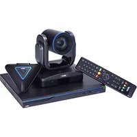
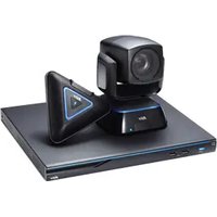
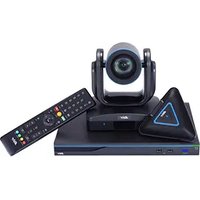
VC520 Pro - Video conferencing system AVer - Free user manual and instructions
Find the device manual for free VC520 Pro AVer in PDF.
| Product Type | Video Conferencing System |
| Brand | AVer |
| Model | VC520 Pro |
| Power Supply | 12 V DC (power adapter included) |
| Video Connectivity | USB 3.1 Type B, Ethernet (RJ45) |
| Audio Connectivity | Speaker port (blue), camera port (blue), phone input port (red), Line out |
| Control Connectivity | RS232, Ethernet port for IP management |
| Video Resolution | Up to 1080p (not explicitly specified, but typical for PTZ) |
| Camera Functions | Pan/Tilt/Zoom (PTZ), SmartFrame, presets, image flip |
| Audio Functions | Noise suppression, automatic gain control, echo cancellation, keyboard noise suppression |
| Remote Control | Infrared remote control (AAA batteries not included) |
| Network Management | IP streaming (RTSP, RTMP), web-based configuration interface, AVer IP Finder |
| Control Software | AVer PTZApp (Windows) for advanced settings and firmware updates |
| Application Compatibility | Zoom, Microsoft Teams, Skype, Google Hangouts, Cisco WebEx, etc. |
| Mounting | On stand or wall mount (L-bracket included) |
| Security | Kensington lock |
| Dimensions (approx.) | Not provided in the manual, estimated ~ 20 x 15 x 15 cm |
| Weight (approx.) | Not provided in the manual, estimated ~ 1.5 kg |
| Maintenance and Cleaning | Wipe with a soft, dry cloth; avoid abrasive products |
| Spare Parts and Repairability | Not specified; contact AVer support |
Frequently Asked Questions - VC520 Pro AVer
User questions about VC520 Pro AVer
0 question about this device. Answer the ones you know or ask your own.
Ask a new question about this device
Download the instructions for your Video conferencing system in PDF format for free! Find your manual VC520 Pro - AVer and take your electronic device back in hand. On this page are published all the documents necessary for the use of your device. VC520 Pro by AVer.
USER MANUAL VC520 Pro AVer
natural_image
Technical line drawing of a mechanical device with two views: top shows a cylindrical component, bottom shows a circular housing (no text or symbols)VC520 Pro
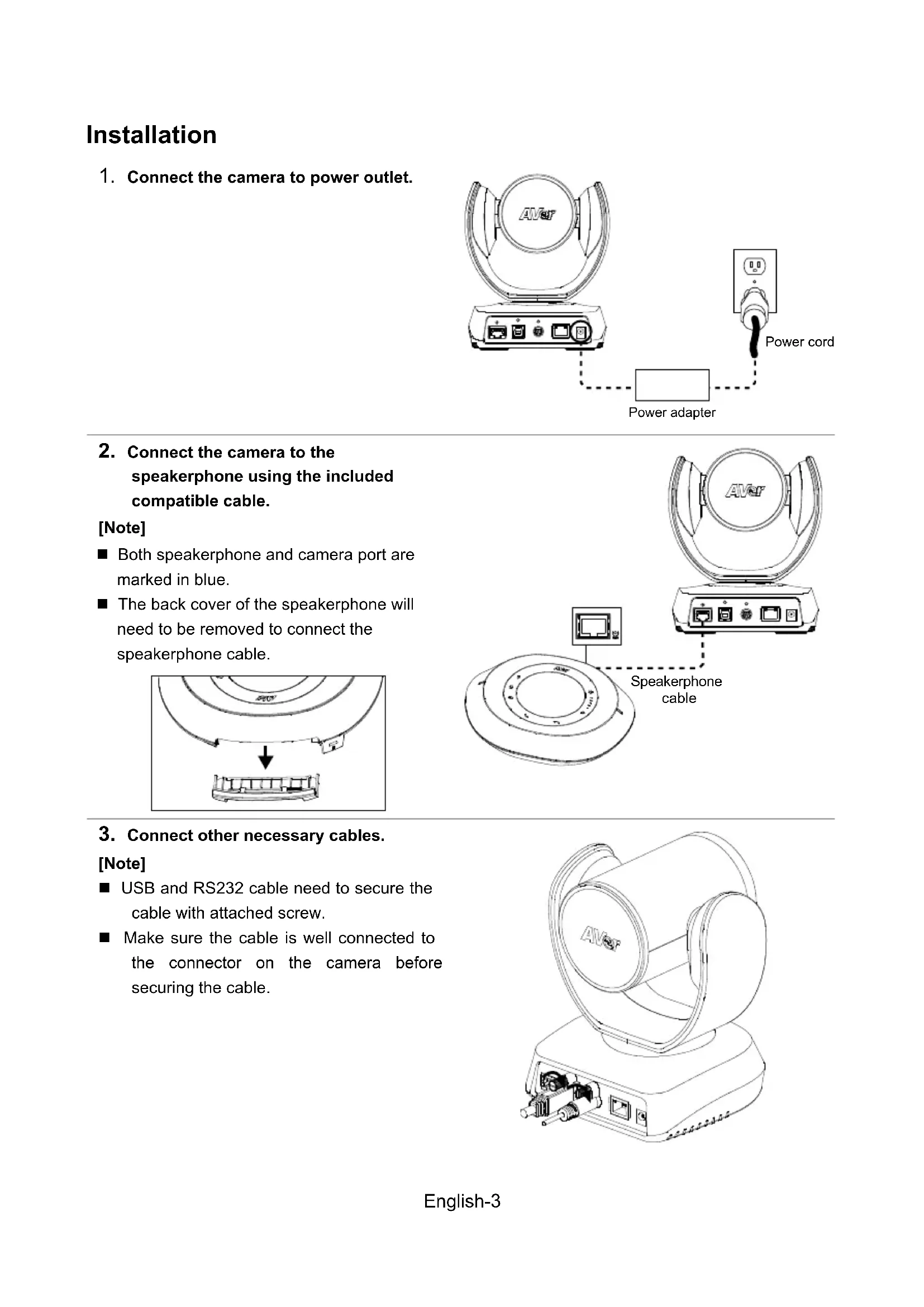
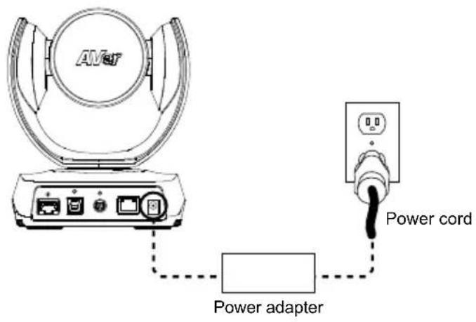
*The power cord will vary depending on the standard power outlet of the country where it is sold.
More Help
For FAQs, technical support, software and user manual download, please visit: http://www.aver.com.
Overview
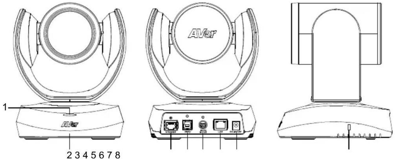
1 Status LED 5 RS232 in/out port
2 IR sensor 6 Ethernet port
3 Speakerphone port 7 DC 12V power jack (Blue cable)
4 USB3.1 Type B port 8 Kensington Lock
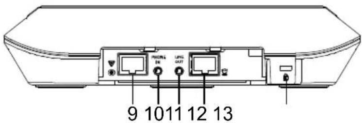
9 Speakerphone port 11 Line out port
(For extended speakerphone and microphone connection/ 12 Camera port (Blue cable)
Red cable) 13 Kensington Lock
10 Phone in port
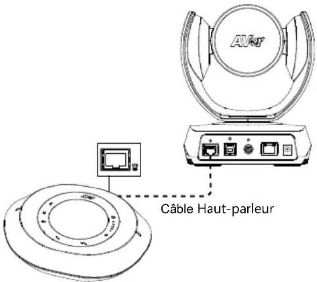
Installation
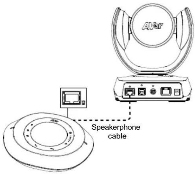
- Connect the camera to power outlet.
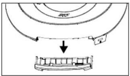
- Connect the camera to the speakerphone using the included compatible cable.
[Note]
■ Both speakerphone and camera port are marked in blue.
■ The back cover of the speakerphone will need to be removed to connect the speakerphone cable.
- Connect other necessary cables.
[Note]
■ USB and RS232 cable need to secure the cable with attached screw.
■ Make sure the cable is well connected to the connector on the camera before securing the cable.
![AVer VC520 Pro - [Note] - 1](/content/2026/03/517454/images/724fe91072640e227ab6c641cd65eab7ef079d9c5a1a6cbddc99f170fd82fc6b.jpg)
natural_image
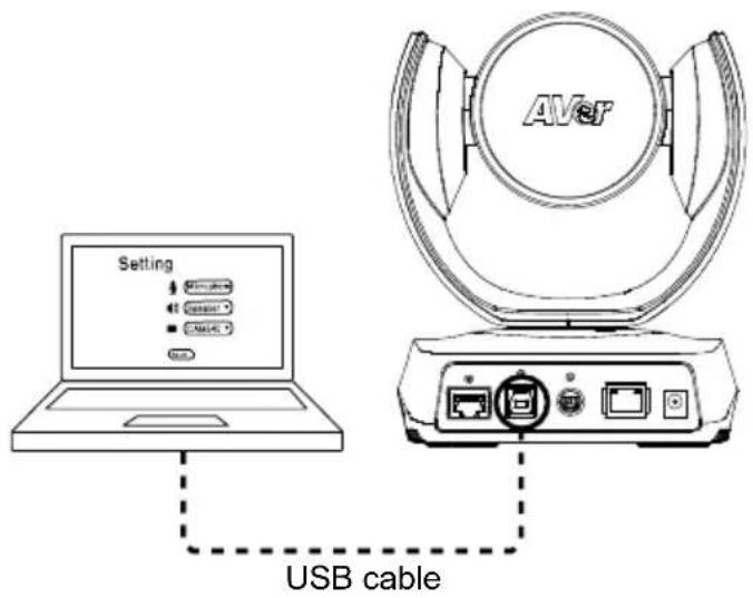
Line drawing of an AVSP radio equipment with base and control panel (no text or symbols)4. Connect the camera to the computer.
[Note] Use the USB 3.0 cable that is included in package.
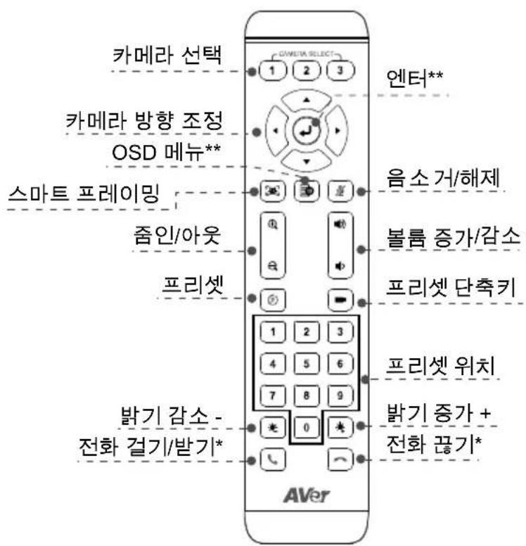
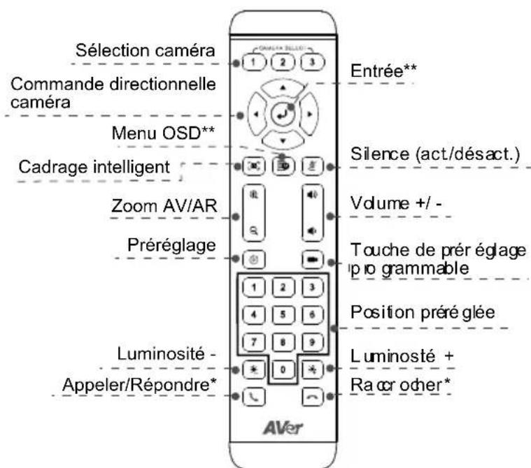
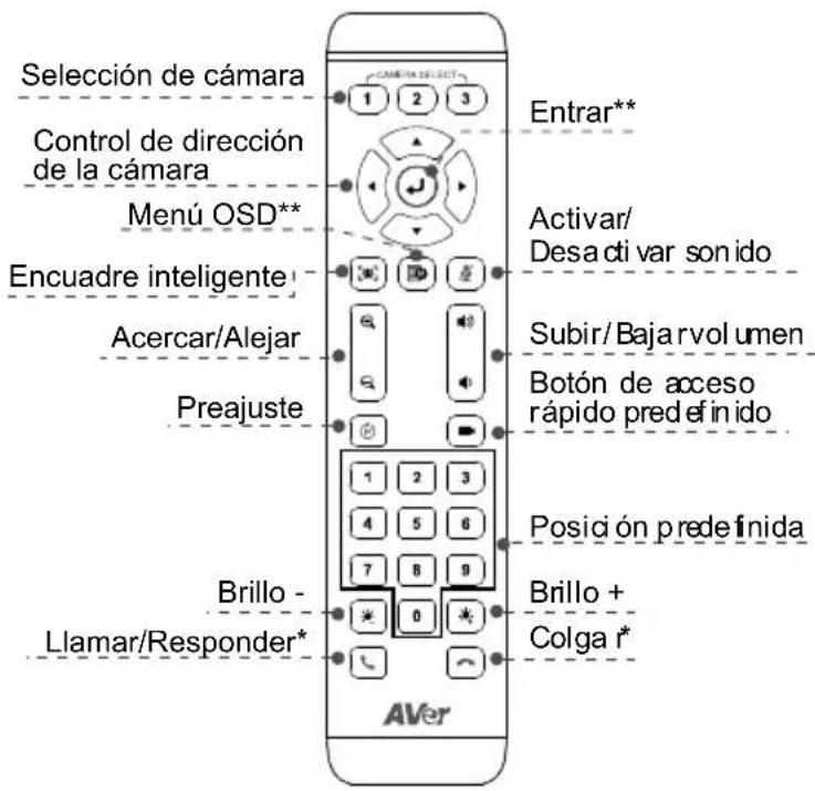
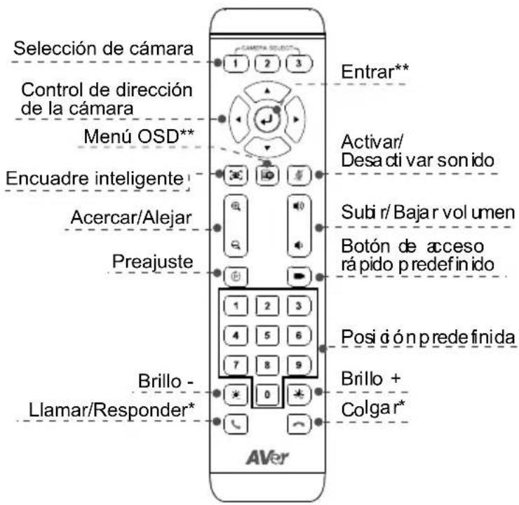
Remote Controller
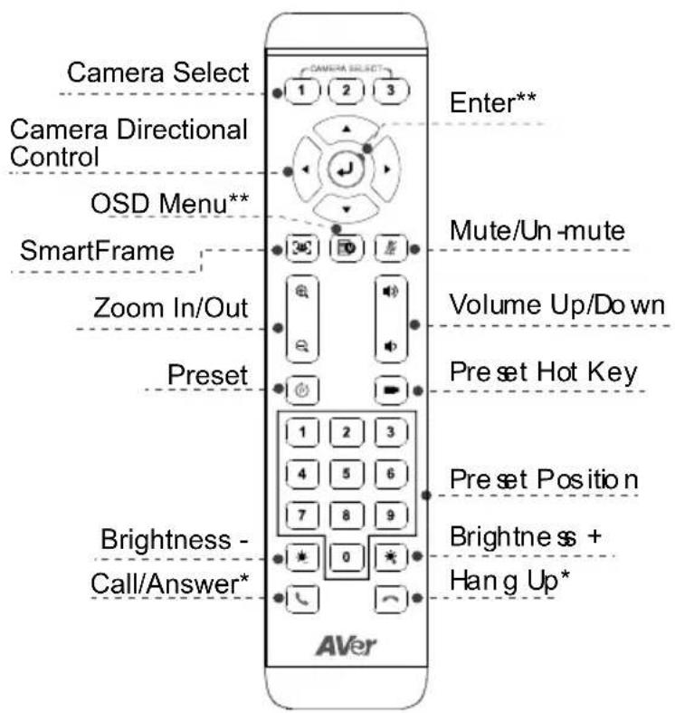
*Function requires AVer PTZApp
**Not supported for VC520 Pro
■ Camera Select: If you only have one camera and don't need to adjust custom settings, the default is camera 1. If you press camera 2 or 3 on the remote control, you will find your remote can't control your camera. In this case, please press camera 1 on your remote again.
■ SmartFrame: Press and hold on the remote for 2 seconds to switch the SmartFraming function between auto and manual mode; a message (as figure shown) will display on the screen to indicate auto or manual mode.
Auto Framing
Manual Framing
[Note] While in the video conference meeting, participants must face the camera for proper face detection (SmartFrame). Side facial profiles are not detectable.
■ Press and hold the number button "1" to turn the WDR function on or off.
■ AAA Batteries (required)
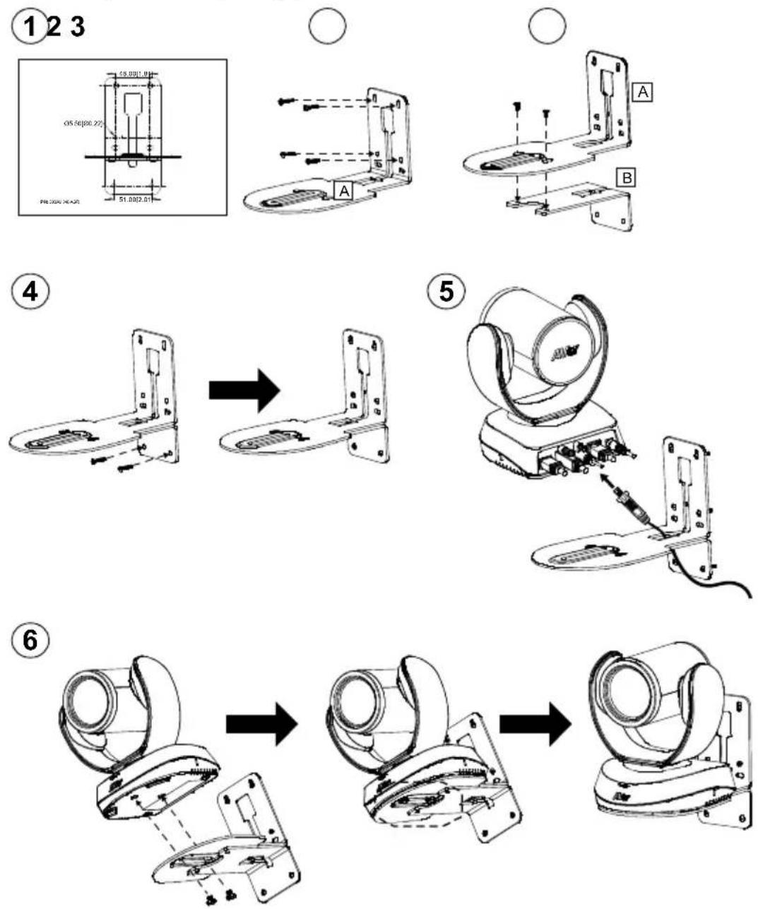
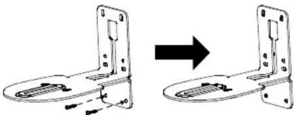
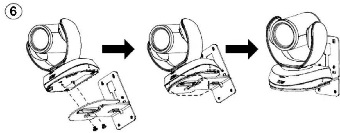
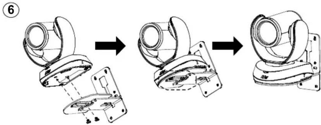
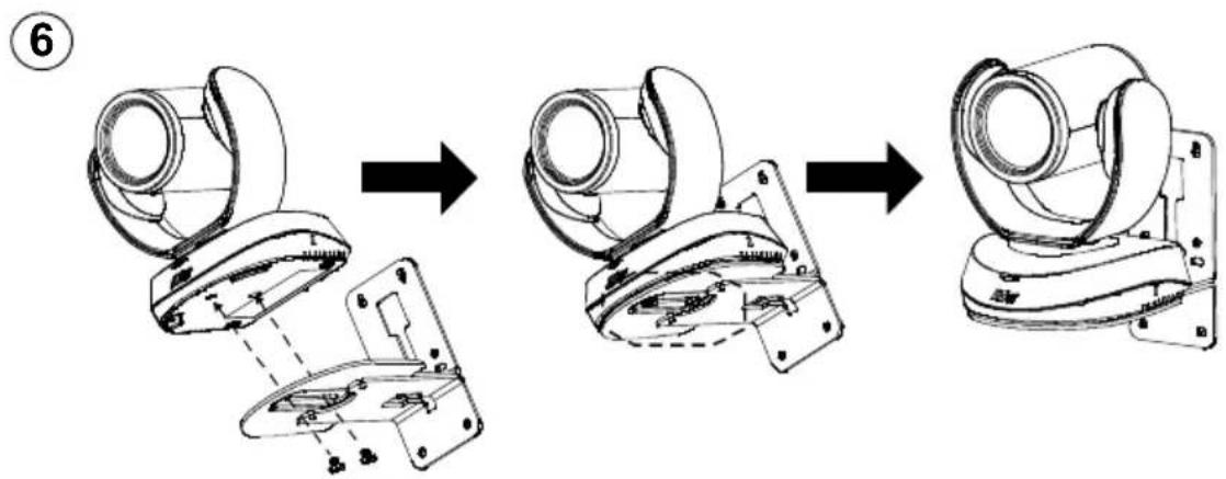
Wall Mount Installation
- Use the drilling paper included in the package to drill the holes in the wall where the user wants to mount the camera.
- Use the screw to secure the A L-mount bracket on the wall.
- Then, assemble the A + B L-mount bracket with screws (included in package).
- After assembling the L-mount bracket, secure the lower part of L-mount bracket on the wall.
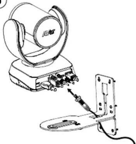
- Pass the cables through the hole on the L-mount bracket and connect the cables to corresponding connection ports.
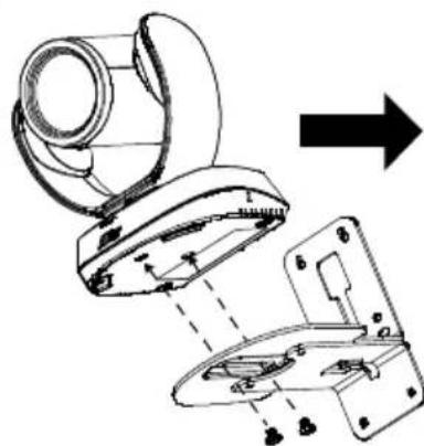
- Use the screws (included in package) to secure the cameras on the L-mount bracket.
Making a Video Call
A computer is required to use this device.
Step 1: Open your video collaboration application such as Zoom, Microsoft ^® Teams, Skype for Business, Skype, Google Hangouts, Intel ^® Unite ^™ , RingCentral, BlueJeans, V-Cube, LiveOn, CyberLink U Meeting ^® , TrueConf, Adobe Connect, Cisco WebEx ^® , Fuze, GoToMeeting ^™ , Microsoft ^® Lync ^™ , Vidyo, vMix, WebRTC, Wirecast, XSplit.
Step 2: Set the VC520 Pro as your primary camera device in your application (Please consult your application setup guide for details).
Step 3: Ready to make a video call.
[Note] VC520 Pro is a plug-n-play conference camera. The system requires no special drivers. For advanced setting and firmware update, please download AVer PTZApp.
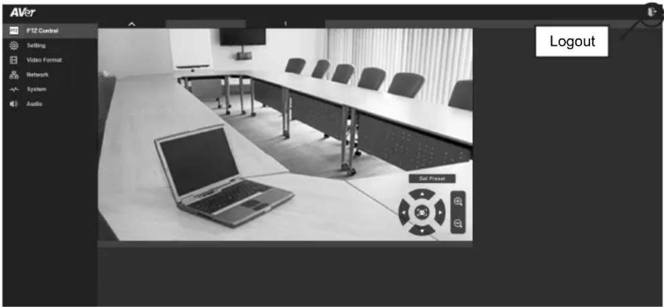
Setup the Camera through the Web Browser
VC520 Pro has an Ethernet port for IP streaming and allows administrators to remotely control and set up the camera via an internet access. Moreover, VC520 Pro also supports RTSP and RTMP functions. For further details, please refer to user's manual or contact our technical support.
-
Make sure the VC520 Pro has an internet access connection.
-
Open the browser and enter the IP address of the camera.
[Note] The browser supports:
- Chrome: version 76.x or above
- Firefox: version 69 or above
- IE: Doesn't support
The camera default IP address is 192.168.1.168. User can use "AVer IP Finder" app to find the camera (Please refer to "Using AVer IP Finder to Find the Camera" section).
- When login screen is shown, enter the password (default password is aver4321).
- The web main screen is displayed.
English-6
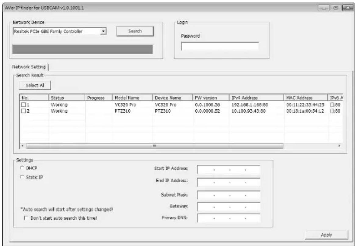
Using AVer IP Finder to find the Camera
To find the IP address of your cameras, you can use the AVer IP Finder application. Follow the below steps to find the IP address of camera.
Download the IP Finder from http://www.aver.com/download-center.
- Run the IP Finder.
- Click "Search", and all available devices will be listed on the screen.
- Select a camera from the list. The corresponding fields of IP address will display.
- To change the IP address of camera, select "DHCP" or "Static IP".
The DHCP should get the IP address from local dynamic IP sever. The static IP, user can enter the specific IP address. Click "Apply" to apply the setting to the camera. The login password is required (default password is aver4321; same as web access password).
- Click "Search" button to re-scan the camera.
- Double-click on the IP address of camera from the list can connect to camera through the browser.
[Note] If IP Finder cannot find the camera, please check following:
■ Please make sure the Ethernet connection of camera is well connected.
■ The camera and PC (IP Finder) are in the same LAN segment.
Install AVer PTZApp
In AVer PTZApp, user can configure the parameters of the camera.
Please go to http://www.aver.com/download-center to download the AVer PTZApp. After downloading, double-click on the file and follow the on-screen instructions to complete the installation.
Use AVer PTZApp
- After installing the AVer PTZApp, double-click on the AVer PTZApp icon to run the application.
- During your video call, you can use the AVer PTZApp to pan, tilt and zoom the camera in/out and enable/disable the backlight feature, set up camera Home or Sleep mode preset points. For more details, please refer to the user manual.
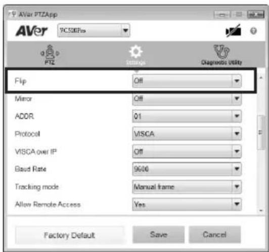
- Tracking mode: It is a SmartFrame function which can auto detect faces of people to find the best view for all meeting participants. Users can change SmartFrame function status in AVer PTZApp. In AVer PTZApp, select "Settings" > "Tracking mode" > "Auto frame/Manual frame/off".
Also, pressing the remote for 1 second can switch the SmartFrame function between auto and manual; a message (as figure shown) will display on the screen to indicate in auto or manual status.
[Note] While in conferencing meeting, participants must face the camera for face detection. The side face is not detectable.
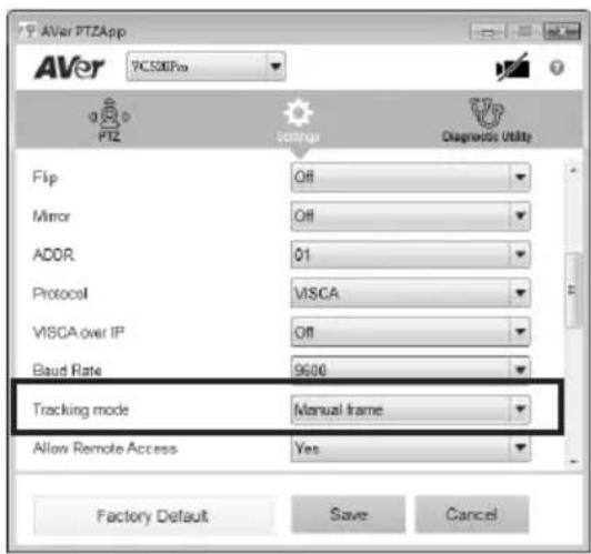

- Flip: If the camera is installed in the upside down position, please enable the "Flip" function in the AVer PTZApp, and the screen will display normally.
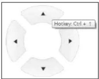
- Hotkey Control: Enable hotkey control to use keyboard control camera's movement and backlight. The default is off.
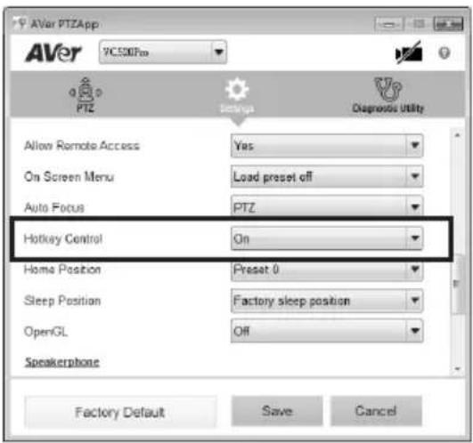
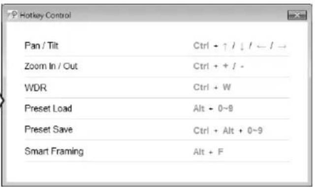
A hotkey tip will display when mouse is moved to the PTZ control button in PTZ mode.
If the hotkey function is enabled after installing the PTZApp, PTZApp auto launch next time the PC reboots. Therefore, the customer can use all the hotkey commands when PTZApp is auto running in system tray.
-
Speakerphone: setup speakerphone function parameters.
-
Nosie suppression: Reduce ambient noise.
- Automatically gain control: Enable/disable the auto gain control.
- Echo cancellation: Enable/disable echo situation.
- Keyboard noise suppression: Enable/disable keyboard noise reduction.
- Phone in jack
➢ Phone in: When the mobile phone is connecting to Phone in port, please select "Phone in" option.
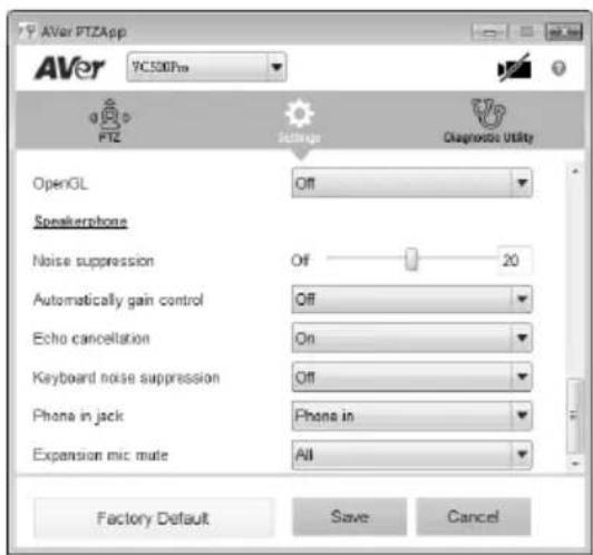
3.5 mm microphone only: The speakerphone will transfer the sound that it receives from the external microphone (connected on phone in port) to far site.
3.5 mm microphone mix in: The speakerphone will transfer the sound that it receives from the external microphone (connected on phone in port) and speakerphone to far site.
- Expansion mic mute
All: To mute all connected speakerphones.
Individual: To individually mute a speakerphone and not the extended speakerphones.
Contact Information
Global
AVer Information Inc.
www.aver.com
8F, No.157, Da-An Rd., Tucheng Dist.,
New Taipei City, Taiwan
European Headquarters
AVer Information Europe B.V.
Westblaak 140, 3012KM, Rotterdam, Netherland
Tel: +31(0)10 7600 550
Technical support: EU.RMA@aver.com
Federal Communication Commission Interference Statement
NOTE: This equipment has been tested and found to comply with the limits for a Class A digital device, pursuant to part 15 of the FCC Rules. These limits are designed to pro-vide reasonable protection against harmful interference when the equipment is operate din a commercial environment. This equipment generates, uses, and can radiate radiofrequency energy and, if not installed and used in accordance with the instruction manual, may cause harmful interference to radio communications. Operation of this equipment in a residential area is likely to cause harmful interference in which case the user will be required to correct the interference at his own expense.
FCC Caution: Any changes or modifications not expressly approved by the party responsible for compliance could void the user's authority to operate this equipment.
This device complies with part 15 of the FCC Rules.
Operation is subject to the following two conditions:
(1) This device may not cause harmful interference, and
(2) this device must accept any interference received, including interference that may cause undesired operation.
Warning:
This is a class A product. In a domestic environment this product may cause radio interference in which case the user may be required to take adequate measures.
CAUTION
- Risk of explosion if battery is replaced by an incorrect type.
- Dispose of used batteries in a safe and proper manner.
©2020 AVer Information Inc. All rights reserved.
빠른 설치 가이드
포장 내용물
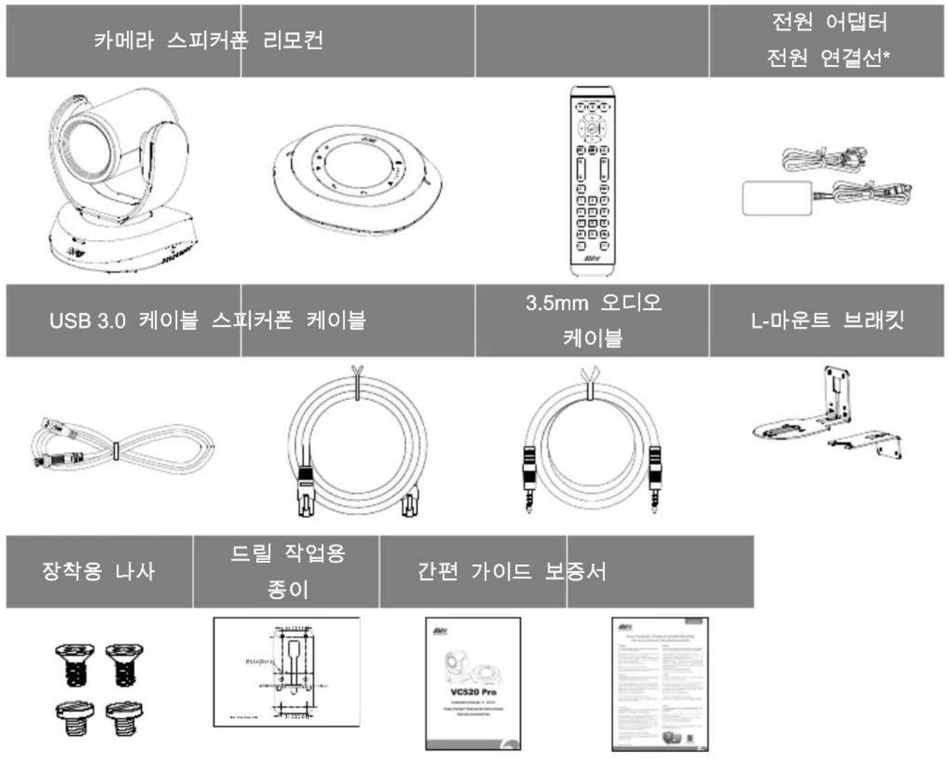
natural_image
Line drawing of an AVSP radio equipment with a base unit and ports (no text or symbols)리모컨
4
natural_image
Diagram showing a mechanical assembly before and after transformation, with no visible text or symbols5
natural_image
Line drawing of a device with attached cable and connector, no text or symbols present6
natural_image
Technical line drawing of a mechanical device with exploded view and assembly, showing internal components and alignment (no text or symbols)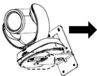
natural_image
Technical line drawing of a mechanical device with an arrow indicating direction (no text or symbols present)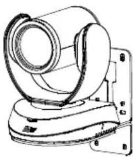
natural_image
Technical line drawing of a mechanical device with no visible text or symbols화상 전화하기
©2020 AVer Information Inc. All rights reserved.
natural_image
Line drawing of an AV4F airship with attached fan and base (no text or symbols)Télécommande
Installation du support mural
8F, No.157, Da-An Rd., Tucheng Dist.,
New Taipei City
Taiwan
Siège européen
AVer Information Europe B.V.
Westblaak 140, 3012KM, Rotterdam, Pays-Bas
Tel: +31(0)10 7600 550
Assistance technique : EU.RMA@aver.com
natural_image
Technical line drawing of a mechanical device with a central bracket and base (no text or symbols)natural_image
Diagram showing a mechanical assembly with concentric circular components and a base structure, no text or symbols present.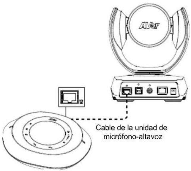
natural_image
Line drawing of an AV-OF airship device with attached ports and fan (no text or symbols)Mando a distancia
8F, No.157, Da-An Rd., Tucheng Dist.,
New Taipei City
Taiwan
Sede europea
AVer Information Europe B.V.
Westblaak 140, 3012KM, Rotterdam,
Netherland
Tel.: +31(0)10 7600 550
natural_image
Technical line drawing of a mechanical device with a curved top and base (no text or symbols)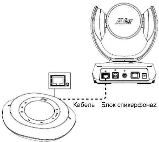
natural_image
Line drawing of an AV6F airship with attached fan and ports (no text or symbols)Пульт ДУ
8F, No.157, Da-An Rd., Tucheng Dist.,
New Taipei City, Taiwan
- VC520 Pro
- More Help
- Installation
- [Note]
- Connect the camera to the computer.
- Auto Framing
- Manual Framing
- Wall Mount Installation
- Making a Video Call
- Setup the Camera through the Web Browser
- Using AVer IP Finder to find the Camera
- Install AVer PTZApp
- Use AVer PTZApp
- Contact Information
- Global
- European Headquarters
- Federal Communication Commission Interference Statement
- Warning:
- CAUTION
- 빠른 설치 가이드
- 포장 내용물
- 리모컨
- 화상 전화하기
- Télécommande
- Installation du support mural
- Siège européen
- Mando a distancia
- Sede europea
- Пульт ДУ
Brand : AVer
Model : VC520 Pro
Category : Video conferencing system