SCCB1310P - Soundbar SAMSUNG - Free user manual and instructions
Find the device manual for free SCCB1310P SAMSUNG in PDF.

User questions about SCCB1310P SAMSUNG
0 question about this device. Answer the ones you know or ask your own.
Ask a new question about this device
Download the instructions for your Soundbar in PDF format for free! Find your manual SCCB1310P - SAMSUNG and take your electronic device back in hand. On this page are published all the documents necessary for the use of your device. SCCB1310P by SAMSUNG.
USER MANUAL SCCB1310P SAMSUNG
Thank you for purchasing this Samsung product. To receive a more complete service, please visit our website
www.samsungsecurity.com

safety precautions
CAUTION
RISK OF ELECTRIC SHOCK. DO NOT OPEN

CAUTION: TO REDUCE THE RISK OF ELECTRIC SHOCK, DO NOT REMOVE COVER (OR BACK) NO USER-SERVICEABLE PARTS INSIDE REFER SERVICING TO QUALIFIED SERVICE PERSONNEL


This symbol indicates that dangerous voltage constituting a risk of electric shock is present within this unit.
This symbol indicates that there are important operating and maintenance instructions in the literature accompanying this unit.
WARNING
- To reduce the risk of fire or electric shock, do not expose this appliance to rain or moisture.
- To prevent injury, this apparatus must be securely attached to the floor/wall in accordance with the installation instructions.
WARNING
- Be sure to use only the adapter that is certified as "Class 2" according to NFPA 70. Using any other adapter could cause fire, electrical shock, or damage to the product.
-
Incorrectly connecting the power supply or replacing battery may cause explosion, fire, electric shock, or damage to the product.
-
Do not connect multiple cameras to a single adapter. Exceeding the capacity may cause abnormal heat generation or fire.
- Securely plug the power cord into the power receptacle. Insecure connection may cause fire.
- When installing the camera, fasten it securely and firmly. The fall of camera may cause personal injury.
- Do not place conductive objects (e.g. screwdrivers, coins, metal parts, etc.) or containers filled with water on top of the camera. Doing so may cause personal injury due to fire, electric shock, or falling objects.
- Do not install the unit in humid, dusty, or sooty locations. Doing so may cause fire or electric shock.
- If any unusual smells or smoke come from the unit, stop using the product. In such case, immediately disconnect the power source and contact the service center. Continued use in such a condition may cause fire or electric shock.
- If this product fails to operate normally, contact the nearest service center. Never disassemble or modify this product in any way. (SAMSUNG is not liable for problems caused by unauthorized modifications or attempted repair.)
- When cleaning, do not spray water directly onto parts of the product. Doing so may cause fire or electric shock.
- This installation should be made by a qualified service person and should conform to all local codes.
CAUTION
- Do not drop objects on the product or apply strong blows to it.
Keep away from a location subject to excessive vibration or magnetic interference. - Do not install in a location subject to high temperature (over 122^ F), low temperature (below 14^ F), or high humidity. Doing so may cause fire or electric shock.
- If you want to relocate the already installed product, be sure to turn off the power and then move or reinstall it.
- Remove the power plug from the outlet when there is a lighting storm.
Neglecting to do so may cause fire or damage to the product. - Keep out of direct sunlight and heat radiation sources. It may cause fire.
- Install it in a place with good ventilation.
- Avoid aiming the camera directly towards extremely bright objects such as sun, as this may damage the CCD image sensor.
- Apparatus shall not be exposed to dripping or splashing and no objects filled with liquids, such as vases, shall be placed on the apparatus.
- The Mains plug is used as a disconnect device and shall stay readily operable at any time.
important safety instructions
- Read these instructions.
- Keep these instructions.
- Heed all warnings.
- Follow all instructions.
- Do not use this apparatus near water.
- Clean only with dry cloth.
- Do not block any ventilation openings. Install in accordance with the manufacturer's instructions.
- Do not install near any heat sources such as radiators, heat registers, or other apparatus (including amplifiers) that produce heat.
- Do not defeat the safety purpose of the polarized or grounding-type plug.
A polarized plug has two blades with one wider than the other.
A grounding type plug has two blades and a third grounding prong.
The wide blade or the third prong is provided for your safety.
If the provided plug does not fit into your outlet, consult an electrician for replacement of the obsolete outlet.
- Protect the power cord from being walked on or pinched particularly at plugs, convenience receptacles, and the point where they exit from the apparatus.
- Only use attachments/accessories specified by the manufacturer.
- Use only with cart, stand, tripod, bracket, or table specified by the manufacturer, or sold with the apparatus. When a cart is used, use caution when moving the cart/apparatus combination to avoid injury from tip-over.
- Unplug this apparatus when a card is used. Use caution when moving the cart/ apparatus combination to avoid injury from tip-over.
- Refer all servicing to qualified service personnel.
Servicing is required when the apparatus has been damaged in any way, such as power-supply cord or plug is damaged, liquid has been spilled or objects have fallen into the apparatus, the apparatus has been exposed to rain or moisture, does not operate normally, or has been dropped.

Apparatus shall not be exposed to dripping or splashing and no objects filled with liquids, such as vases, shall be placed on the apparatus

contents
OVERVIEW
07
FEATURES
08
INSTALLATION
09
SPECIFICATIONS
19
7 Overview
8 Features
9 Package
9 Parts & Description
10 Things to keep in mind during Installation and Use
10 Connect the auto iris lens connector
11 Install the lens
11 Adjust the back focus
12 Connect the cables and check the operation
16 Assemble the parts
19 Specifications
overview
It is a high-resolution box camera that has implemented the horizontal resolution of 380 lines by taking advantage of the Digital Signal Processing and OLPF technologies.
- In mechanical fluorescent lighting conditions, you can experience so-called “color rolling” if you have installed the manual iris lens on the camera and positioned the function switch from ELC to ON. In this case, connect the camera to the power source (AC) and position the L/L switch on the rear panel to EXT. (PAL : 50Hz)
- What is Color Rolling?
This occurs because the mechanical fluorescent lighting blinks from power frequencies, where the color temperature input to the camera is not certain so the color on the screen changes irregularly (red, blue, yellow, etc).
- This problem can be solved by using the Line Lock function or the Auto Iris Lens.
features
| High Color Sensitivity | The camera adopts the latest 1/3" Super-HAD IT CCD to get the benefit of high color sensitivity. |
| Resolution | Introduces Full Digital Image Processing from the digital signal technology to implement a high-resolution image. |
| Excellent Back Light Compensation | This will guarantee a sharp image by compensating for the back light even if the sunlight or bright lighting reflects against the subject. |
| Digital Power Synchronization | Adopts the full digital line lock system to enable you to adjust the vertical synchronization of the camera, an enhancement of manipulation and reliability. |
| Dynamic CCD Defect Compensation | Uses advanced technology to compensate CCD defects in any mode, to give clear, sharp and noise-free images, even in low contrast scenes. |
installation
In this chapter, we will provide you with general instructions for product installation and preferred places as well as considerations before installation. Now, let's install the camera and connect necessary cables.
Package
You must check that all the components and accessories listed below are included in the product package.
Camera
Camera Holder (Mount Adaptor) screw x2
User's guide
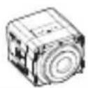
Parts & Description
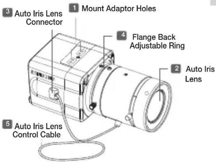
text_image
3 Auto Iris Lens Connector 1 Mount Adaptor Holes 4 Flange Back Adjustable Ring 2 Auto Iris Lens 5 Auto Iris Lens Control Cable1 Mount Adaptor Holes
Used to fix the mount adaptor with a screw if you want to mount the camera on the bracket.
2 Auto Iris Lens (Optional)
A lens to be installed on the camera - If the camera gets dirty on the surface of the lens, apply ethanol to the provided tissue or a dry cloth and wipe it out.
3 Auto Iris Lens Connector
Provides power source and control/ DC signal with iris lens that are required to control the iris of the lens
4 Flange Back Adjustable Ring
Used to adjust the back focus of the camera.
5 Auto Iris Lens Control Cable
Transfers the control signal from the camera to the iris lens.
Things to keep in mind during installation and Use
• Do not disassemble the camera on your own.
- Always be careful when handling the camera. Do not strike the camera by your fists or shake it. Please be careful not to be careless when storing and operating it.
- Do not place or operate the camera in any wet environment such as rain or wet surfaces.
- Do not clean the camera with rough sandpaper. Please always use a dry cloth when cleaning it.
- Put the camera in a cool area free from direct sunlight. Otherwise, the camera may be damaged.
Connect the auto iris lens connector
Remove the sheath round the iris control cable and connect it to each of the auto iris lens connector as described below.
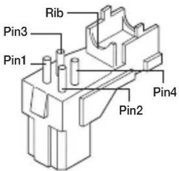
text_image
Rib Pin3 Pin1 Pin4 Pin2| Pin Number | DC Control Type |
| 1 Damp(-) | |
| 2 Damp(+) | |
| 3 Drive(+) | |
| 4 Drive(-) | |
• This connector is not provided.
Install the lens
Loosen the single screw on the adjustable ring of the flange back by turning it anti-clockwise and turn the ring in the "C" direction (anti-clockwise) to the end. Otherwise, it can cause damage to the internal image sensor or the lens when you install the lens on the camera.
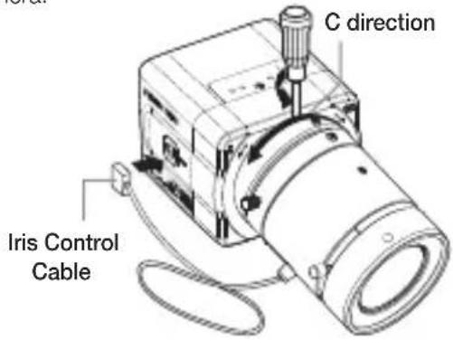
text_image
C direction Iris Control CableAdjust the back focus
The back focus of a camera is predefined by the factory default. However, some models are out of focus depending on the lens type. If your camera is out of focus, follow the instructions below to adjust the back focus. The following is the procedure used to set the proper back focus point in fixed focus lenses.
Lens without zooming feature
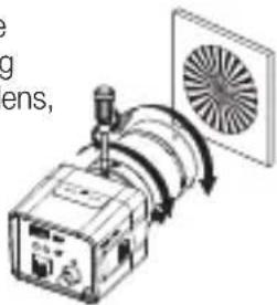
- Capture a sharp subject (with a grid pattern) more than 10m apart and adjust the focus ring to the infinity ( ).
- Adjust the adjustable ring of the flange back so that you can capture the sharpest image.
- Fasten the screw of the adjustable ring of the flange back.
Lens with zooming feature
- Capture a sharp subject (with a grid pattern) 3-5m apart and adjust the zoom in the TELE (zooming) direction as possible and also adjust the focus ring so that you can capture the sharpest image.
- Adjust the zoom in the WIDE direction as possible and turn the adjustable ring of the flange back so that you can capture the sharpest image.
- Repeat 1 and 2 above 2-3 times to match the focus from the ZOOM TELE side with that from the ZOOM WIDE side.
- Fasten the screw of the adjustable ring of the flange back.
- If you darken the image before adjusting the focus by attaching the ND filter to the front of the lens, you can get a sharper focus.
text_image
Diagram showing a device emitting a fan with labeled components and directional arrows indicating signal flow.Connect the cables and check the operation

text_image
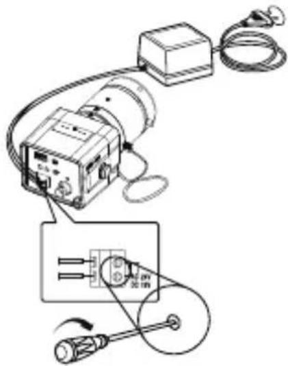
VIDEO LINE AUDIO LINE VIDEO IN Terminal on the rear of monitor BNC Cable VIDEO OUT Terminal- Connect one end of the BNC cable to the VIDEO OUT port of the monitor.
- Connect the other end of the BNC cable to the VIDEO IN port.
- Connect the camera to the power adaptor. Use a slotted flat (-) screwdriver to connect one end of the two-line power adaptor to the DC/AC IN port of the camera. (GND: marked with a white line on the cable)
- You can plug in to a power outlet regardless of the polarity for both AC 24V and DC 12V adaptor.
AC24V/DC12V models
natural_image
Pure electrical circuit lines without any symbolsUse only the adapter that is certified as "Class 2" according to NFPA 70.
AC24V/DC12V
text_image
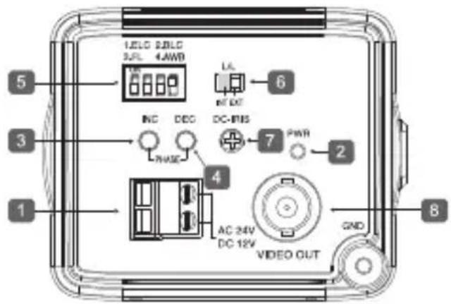
1 2 3 4 5 6 7 8 9 10 LEDG 2.0VDC 3.0L 4AWB NC DEG DC-RIS PWM AC 24V DC 12V GND VIDEO OUT1 Power Port
Port that is connected to the power (adaptor) cable. Connects to AC 24V or DC 12V.
2 Power Indication LED
If properly supplied with power, the LED turns on.
3 Vertical Synchronization Phasing Switch (Left)
Used to adjust the vertical synchronization phasing. If pressed, the vertical synchronization moves to the left.
4 Vertical Synchronization Phasing Switch (Right)
Used to adjust the vertical synchronization phasing. If pressed, the vertical synchronization moves to the right.
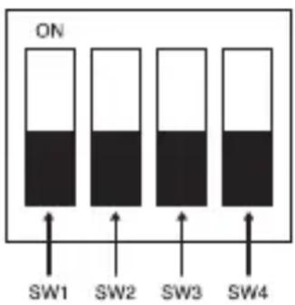
5 FUNCTION SWITCH-1
text_image
ON SW1 SW2 SW3 SW4- ELC
- BLC
- FL(Flickerless)
- AWB
SW1(ELC)
Use this for the manual iris lens. If set to ON, the electronic shutter speed varies between 1/50 and 1/120,000 second to keep the screen brightness proper. However, you must position this switch to OFF if you are using the auto iris lens (DC control type). Because, in this mode, the camera can show the color rolling effect when operating under the mechanical fluorescent lightning. If this happens, apply the AC power and set the L/L to "EXT".
SW2(BLC)
Use to compensate for a display that is too bright or too dark when indoor lighting or windows reflects against the subject. Set to ON for these conditions.
SW3(FL)
It is an anti-flicker system that prevents the flickering of the image due to mismatch between the vertical sync frequency and the on-off frequency of lighting.
It is used when the camera and broadcasting system within its own region do not match each other. If set to ON, the electronic shutter speed stays at either 1/120sec(PAL).

If SW1 (ELC) is set to ON, the anti-flicker system does not work even if SW3 is positioned to ON.
SW4(AWB)
ON(ATW): It automatically adjusts the image color according to the temperature change of the lightning color. Under a very irregular lightning condition (such as car headlight), if set to ON, it captures a subject normally (white).
OFF(AWC): It remembers the normal color temp switch with the OFF to operate at a certain white balance level.

Note that AWB can cause an error in the following conditions:
- If a big subject of a uniform color with a high saturation exists in the center of the screen or if few part of the image is in white.
- If lighting is made of special material like sodium.
6 FUNCTION SWITCH-2
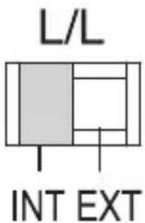
text_image
L/L INT EXTIf multiple cameras are connected to a sequential switcher in auto switch mode, the camera in the internal sync mode causes skip every time it moves to another scene. However, this can be solved by positioning the L/L switch to EXT and using the level bar to adjust the vertical sync phasing.
- INT: It operates in the internal synchronization mode.
- EXT: it operates in the power synchronization mode.
※ If your camera uses DC 12V for power source, it operates in the internal mode regardless of the position (EXT/INT) of the L/L switch.
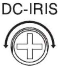
7 DC IRIS Level Bar
text_image
DC-IRISUsed to adjust the iris level of this level bar using a screwdriver.
- Anti-clockwise: Decreases the luminance level.
- Clockwise: Increases the luminance level.

- The IRIS range of the DC lens is about between 80IRE and120IRE. In other words, the DC lens adopts a variable range limitation system, rather than IRIS Full Open/Close system.
- Depending on the type of the lens used that allows setting the value below 75 IRE may cause IRIS hunting. Therefore, make sure that the range is set to an appropriate level (higher than 80 IRE).
8 Video Out Port
Connected to the Video Out port of a monitor. The video signal is output via this port.
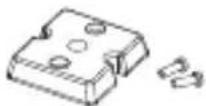
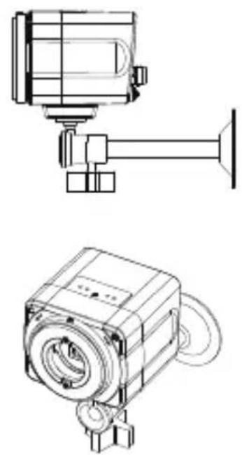
Assemble the parts

text_image
HOLDER-CAMERA SCREW-MACHINE x2 BRACKET-CAMERAUse 2 pieces of SCREW-MACHINE to fix the HOLDER-CAMERA into the lower hole of the camera as shwon, and secure the HOLDER-CAMERA to the BRACKET—CAMERA on the ceiling or wall by fixing the screw.
natural_image
Technical line drawings of a mechanical device with no visible text or symbols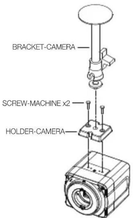
text_image
BRACKET-CAMERA SCREW-MACHINE x2 HOLDER-CAMERA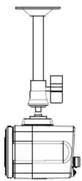
natural_image
Technical line drawing of a mechanical device with a conical top and internal components (no text or symbols)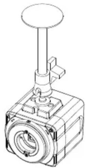
natural_image
Technical line drawing of a mechanical valve component (no text or symbols)Use 2 pieces of SCREW-MACHINE to fix the HOLDER-CAMERA into the lower hole of the camera as shwon, and secure the HOLDER-CAMERA to the BRACKET—CAMERA on the ceiling or wall by fixing the screw.
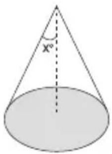
1. Installing a lightening conductor
text_image
X°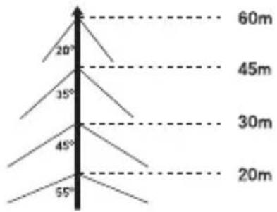
text_image
20° 35° 45° 55° 60m 45m 30m 20ma) Protection area b) Protected angle
(Depending on the height of the lightning conductor)
2. Camera grounding
| No Distinguished by Standard Note | ||
| 1 Grounding method Class 3 CCTV product | ||
| 2 Thickness of the Grounding wire 1.6mm | ^2 | |
| 3 Ground resistance | 100Ω ↓ |
The purpose of the camera grounding
Installing the lightning conductor and grounding the camera chassis prevent the CCTV camera from lightning strikes. When installing the CCTV camera outside, avoid the damages from the lightning strikes by using the lightening conductor and camera grounding.
specifications
SCC-B1310P
| Item Description | |
| Product Type | Surveillance Camera |
| Broadcasting System | PAL STANDARD SYSTEM |
| Imaging Device | 1/3”IT, S-HAD-CCD |
| Number of Effective Pixels | 500(H) X 582(V) |
| Scanning 625 Lines, 2:1 interlace | |
| Line Frequency | INTERNAL : 15.625Hz(H)50Hz(V)LINELOCK : 15.625Hz(H)50Hz(V) |
| Synchronous Mode | INTERNALLINE LOCK (AC 24V) |
| Horizontal Resolution | 380TV Lines |
| S/N Ratio | Approx. 50dB |
| Minimum Subject Illumination | 0.25Lux (F1.2, 50IRE)0.15Lux (F1.2, 30IRE)0.08Lux (F1.2, 15IRE) |
| ALC/ELC | ALC: DC IRIS LENS OnlyELC: Electronic Shutter Iris(max. 1/120Ksec) |
| Item Description | |
| FL(FLICKERLESS) OFF/ON | |
| Lens Manual/Auto Iris DC Lens | |
| Lens Mount | C, CS Lens Adaptable |
| AWB (Auto White Balance) | ON : ATWOFF : AWC |
| BLC (Back Light Compensation) | ON/OFF |
| AGC AUTO | |
| Signal Out | COMPOSITE VIDEO OUT1V p_p 75 Ω / BNC |
| Power | AC24V ±10%(50Hz±0.3Hz),DC12V+10%~5% |
| Power Consumption | Approx. 3 Watts |
| Operation Temperature | -10°C ~ +50°C |
| Operation Humidity | ~90% |
| Dimensions (mm) | 68(W) x 55(H) x 77.1(D) |
| Weight 220 g | |
natural_image
Simple line drawing of a trash bin with crossed lines indicating no waste or discharge (no text or symbols)Correct Disposal of This Product
(Waste Electrical & Electronic Equipment)
(Applicable in the European Union and other European countries with separate collection systems)
This marking on the product, accessories or literature indicates that the product and its electronic accessories (e.g. charger, headset, USB cable) should not be disposed of with other household waste at the end of their working life. To prevent possible harm to the environment or human health from uncontrolled waste disposal, please separate these items from other types of waste and recycle them responsibly to promote the sustainable reuse of material resources.
Household users should contact either the retailer where they purchased this product, or their local government office, for details of where and how they can take these items for environmentally safe recycling.
Business users should contact their supplier and check the terms and conditions of the purchase contract. This product and its electronic accessories should not be mixed with other commercial wastes for disposal.
SCC-B1310P
CAMERA COULEUR NUMERIQUE
natural_image
Diagram of a device emitting a fan with directional arrows indicating airflow (no text or symbols)natural_image
Diagram of an electrical testing setup with a device, cable, and sensor components (no text or labels)text_image
L/L INT EXTnatural_image
Simple circular diagram with a plus sign inside and curved arrows indicating rotation or feedback (no text or symbols)natural_image
Technical line drawing of a mechanical device with no visible text or symbols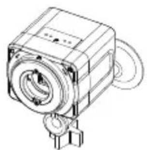
natural_image
Technical line drawing of a mechanical component with no visible text or symbols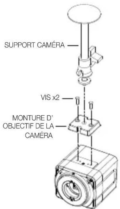
text_image
SUPPORT CAMÉRA VIS x2 MONTURE D' OBJECTIF DE LA CAMÉRA
natural_image
Technical line drawing of a mechanical device with a conical top and internal components (no text or symbols)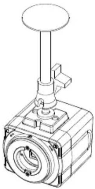
natural_image
Technical line drawing of a mechanical valve assembly (no text or symbols)natural_image
Simple line drawing of a trash bin with crossed lines indicating no waste or discharge (no text or symbols)natural_image
Diagram of a device emitting a fan with directional arrows (no text or symbols)natural_image
Diagram of an electrical testing setup with a device connected to a cable and a sensor, showing wiring connections (no text or labels)text_image
L/L INT EXTnatural_image
Technical line drawing of a mechanical device with no visible text or symbols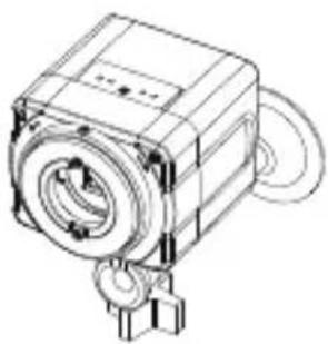
natural_image
Technical line drawing of a mechanical component with no visible text or symbols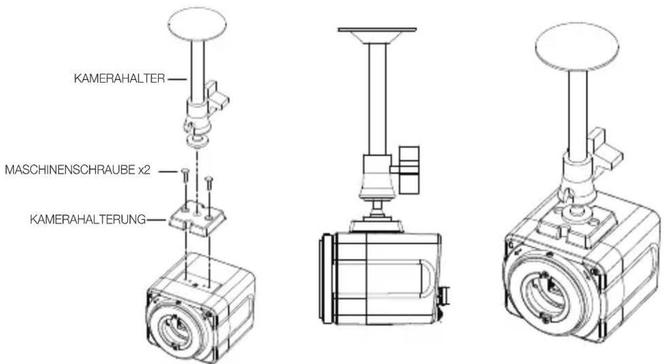
natural_image
Simple line drawing of a trash bin with no text or symbolsCÁMARA COLOR DIGITAL
Manual de usuario
natural_image
Diagram of a device emitting a fan with directional arrows, no text or symbols presentnatural_image
Diagram of an electrical testing setup with a device connected to a cable and a connector (no text or labels)text_image
L/L INT EXTnatural_image
Simple circular diagram with a plus sign and curved arrows, no text or symbols present.natural_image
Technical line drawing of a mechanical device with no visible text or symbols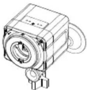
natural_image
Technical line drawing of a mechanical device with no visible text or symbols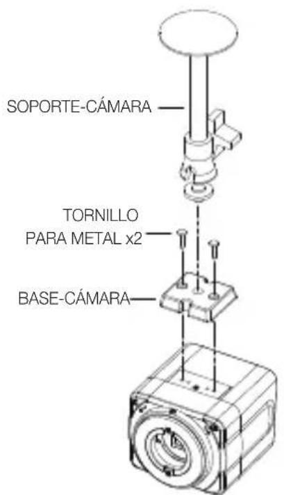
text_image
SOPORTE-CÁMARA TORNILLO PARA METAL x2 BASE-CÁMARA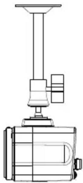
natural_image
Technical line drawing of a mechanical device with a conical top and base (no text or symbols)
natural_image
Technical line drawing of a mechanical valve assembly (no text or symbols)natural_image
Simple line drawing of a trash bin with crossed lines indicating no waste or discharge (no text or symbols)natural_image
Diagram of a device emitting a fan or fan-shaped device with directional arrows (no text or symbols)natural_image
Diagram of an electrical testing setup with a device connected to a cable and a sensor, showing wiring connections (no text or labels)text_image
L/L INT EXTnatural_image
Simple circular diagram with a plus sign inside and curved arrows pointing inward (no text or symbols)natural_image
Technical line drawing of a mechanical device with no visible text or symbols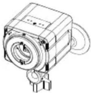
natural_image
Technical line drawing of a mechanical device with no visible text or symbols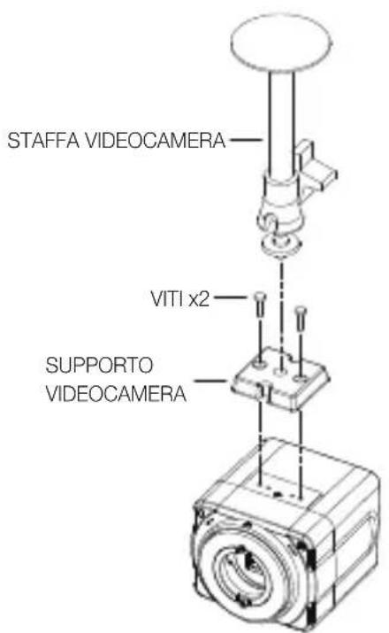
text_image
STAFFA VIDEOCAMERA VITI x2 SUPPORTO VIDEOCAMERA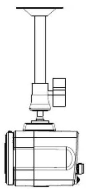
natural_image
Technical line drawing of a mechanical device with no visible text or symbols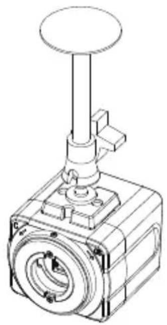
natural_image
Technical line drawing of a mechanical valve assembly (no text or symbols)natural_image
Simple line drawing of a trash bin with crossed lines indicating no waste or discharge (no text or symbols)natural_image
Diagram of a mechanical device with a fan and rotating component (no text or symbols)natural_image
Technical line drawing of a mechanical or electrical component with wires and a sensor, no visible text or symbolstext_image
L/L INT EXTnatural_image
Technical line drawings of two mechanical components: a top view and a side-view view (no text or symbols)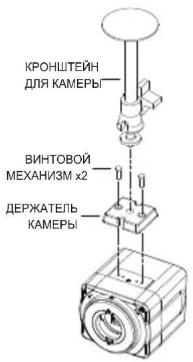
natural_image
Technical line drawing of a mechanical device with a conical top and base (no text or symbols)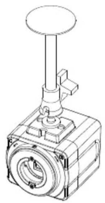
natural_image
Technical line drawing of a mechanical valve or actuator component (no text or symbols)natural_image
Simple line drawing of a trash bin with no text or symbols
natural_image
Diagram of a device emitting a fan with directional arrows indicating motion (no text or symbols)natural_image
Diagram of an electrical testing setup with a device, cable, and connector (no text or labels)text_image
L/L INT EXTnatural_image
Technical line drawing of a mechanical device with no visible text or symbols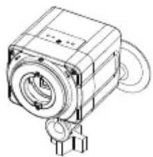
natural_image
Technical line drawing of a mechanical device with no visible text or symbols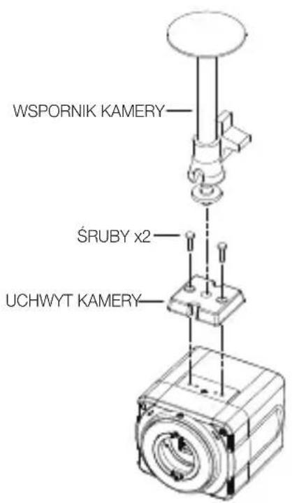
text_image
WSPORNIK KAMERY ŚRUBY x2 UCHWYT KAMERY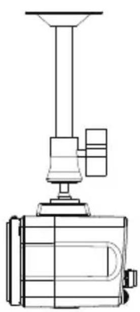
natural_image
Technical line drawing of a mechanical device with a conical top and base (no text or symbols)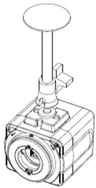
natural_image
Technical line drawing of a mechanical valve or actuator component (no text or symbols)natural_image
Simple line drawing of a trash bin with no text or symbols
natural_image
Technical line drawing of a mechanical or electrical device with wires and components, no visible text or symbolstext_image
L/L INT EXTnatural_image
Technical line drawing of a mechanical device with no visible text or symbols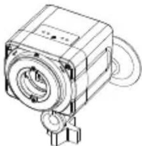
natural_image
Technical line drawing of a mechanical device with no visible text or symbolsnatural_image
Simple line drawing of a trash bin with crossed lines indicating no waste or discharge (no text or symbols)natural_image
Diagram of a device emitting a fan with motion arrows, no text or symbols presentnatural_image
Diagram of an electrical testing setup with a device, cable, and connector (no text or labels)text_image
L/L INT EXTnatural_image
Simple circular diagram with a plus sign inside and curved arrows pointing inward (no text or symbols)natural_image
Technical line drawing of a mechanical device with no visible text or symbols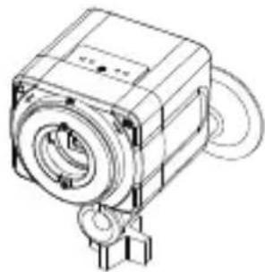
natural_image
Technical line drawing of a mechanical component with no visible text or symbols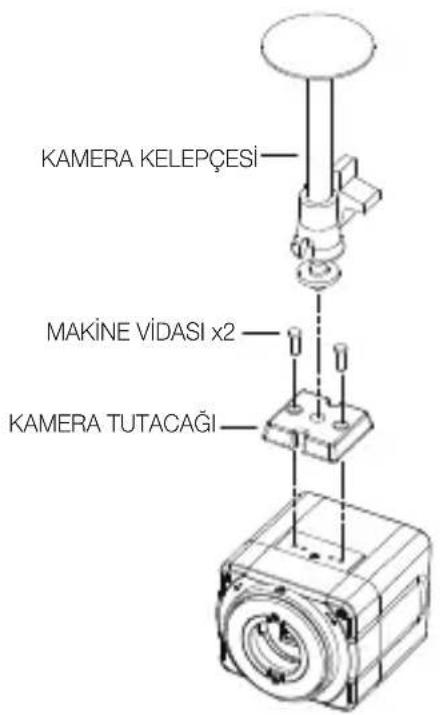
text_image
KAMERA KELEPÇESİ MAKİNE VIDASI x2 KAMERA TUTACAĞI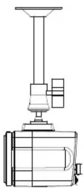
natural_image
Technical line drawing of a mechanical device with a conical top and base (no text or symbols)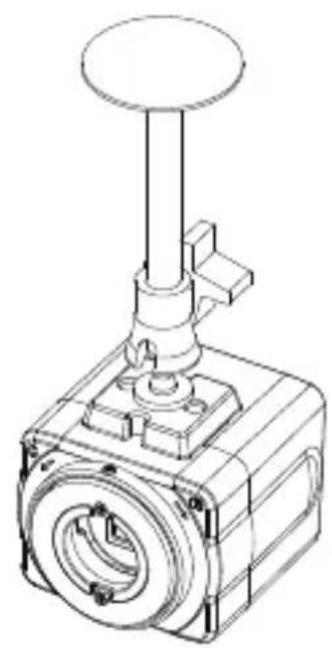
natural_image
Technical line drawing of a mechanical valve assembly (no text or symbols)natural_image
Symbol of a trash bin crossed with a diagonal line, representing no waste or discharge (no text or labels)
This EEE is compliant with RoHS

AB82-02540A-00