MPKDVF6 - Other camera accessories SONY - Free user manual and instructions
Find the device manual for free MPKDVF6 SONY in PDF.
| Product Type | Waterproof Housing for Camcorder |
| Brand and Model | Sony MPK-DVF6 |
| Maximum Operating Depth | 75 meters |
| Dimensions (W x H x D) | Approx. 312 x 212 x 318 mm |
| Weight (Housing Only) | Approx. 4.4 kg |
| Materials | Aluminum alloy, glass, plastic (ABS, PC) |
| Housing Power | CR2 lithium battery for handle |
| LCD Monitor Power | 4 AA alkaline or Ni-MH batteries (optional) |
| Sealing Gasket | Replaceable O-ring (grease supplied) |
| Functions Accessible Underwater | Power on/off, recording start/stop, zoom, photo capture, autofocus on/off |
| Camcorder Compatibility | Sony Handycam Vision DCR-HC, PC, TRV models (detailed list in manual) |
| Supplied Accessories | Mounting brackets (B, D, E, F, G), spacer C, pads, screw plate, screwdriver, A/V conversion cable, wide-angle lens, color filter, lens hood, anti-reflection rings, straps, bag, shoulder strap, CR2 battery, O-ring, grease |
| Recommended Maintenance | Rinse with fresh water after each use, check and grease O-ring, replace O-ring once a year |
| Available Spare Parts | O-ring (ref. 3-977-362-01), grease (ref. 3-071-370-01) |
| Safety Precautions | Do not open underwater; check watertightness before diving; use only supplied grease; do not expose to excessive heat |
Frequently Asked Questions - MPKDVF6 SONY
User questions about MPKDVF6 SONY
0 question about this device. Answer the ones you know or ask your own.
Ask a new question about this device
Download the instructions for your Other camera accessories in PDF format for free! Find your manual MPKDVF6 - SONY and take your electronic device back in hand. On this page are published all the documents necessary for the use of your device. MPKDVF6 by SONY.
USER MANUAL MPKDVF6 SONY
Operating Instructions ____ GB
Mode d'emploi FR
For the customers in U.S.A.
CAUTION
You are cautioned that any changes or modifications not expressly approved in this manual could void your authority to operate this equipment.
NOTE:
This equipment has been tested and found to comply with the limits for a Class B digital device, pursuant to Part 15 of the FCC Rules. These limits are designed to provide reasonable protection against harmful interference in a residential installation. This equipment generates, uses, and can radiate radio frequency energy and, if not installed and used in accordance with the instructions, may cause harmful interference to radio communications. However, there is no guarantee that interference will not occur in a particular installation. If this equipment does cause harmful interference to radio or television reception, which can be determined by turning the equipment off and on, the user is encouraged to try to correct the interference by one or more of the following measures:
– Reorient or relocate the receiving antenna.
– Increase the separation between the equipment and receiver.
- Connect the equipment into an outlet on a circuit different from that to which the receiver is connected.
– Consult the dealer or an experienced radio/TV technician for help.
Table of contents
Features and Precautions ...... 3
Supplied Accessories.... 4
Preparations 5
Preparing your camcorder...... 5
Preparing the marine pack (installing the battery) 12
Installing the camcorder to the marine pack 14
Underwater recording 20
Recording 22
Attaching the supplied accessories 23
Using the underwater video light (optional) 24
Removing the camcorder 25
Note on the O-ring 29
What is an O-ring? 29
How the O-ring waterproofs...... 29
Handling the O-ring 30
Maintenance.... 32
Caution on handling 33
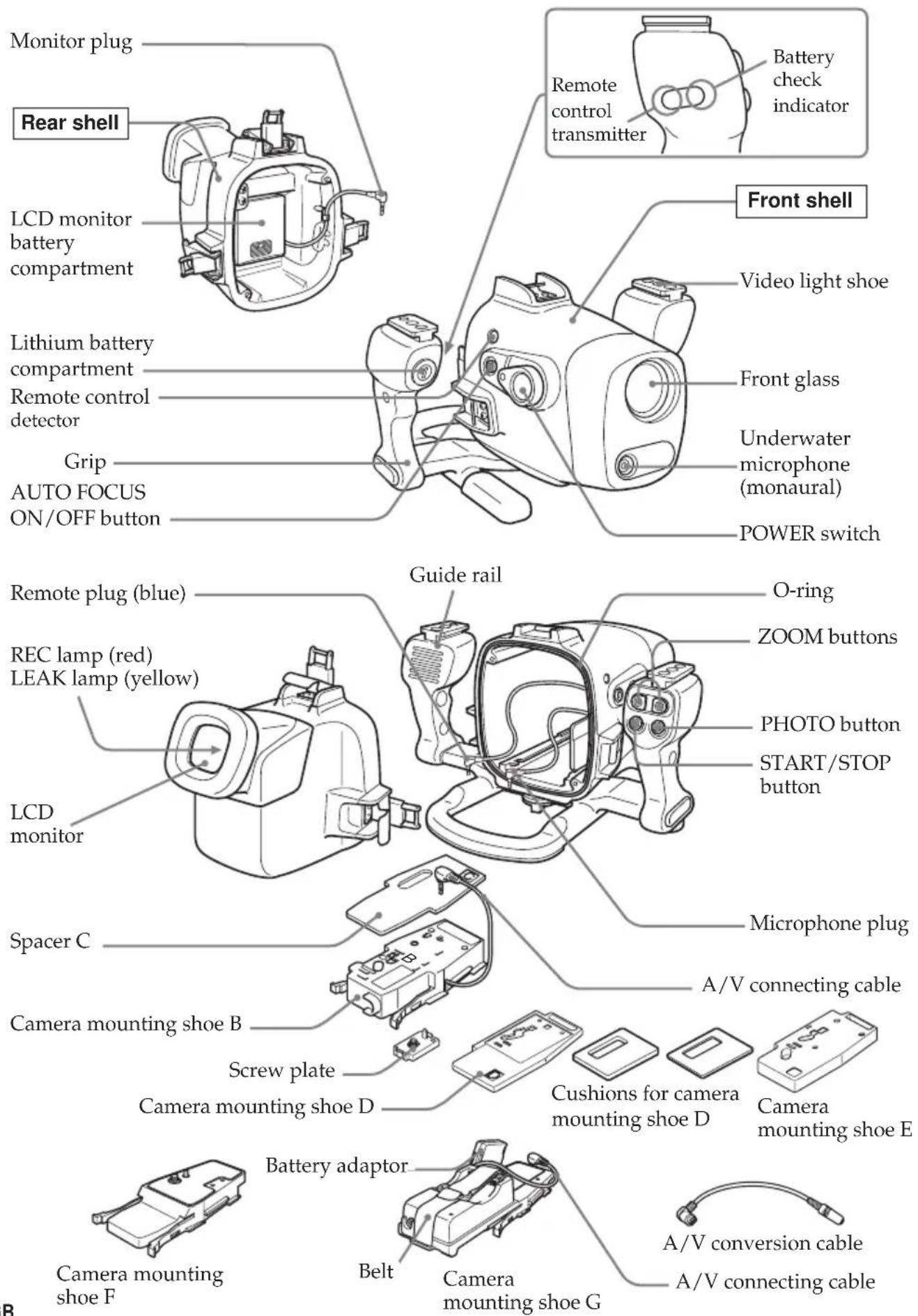
Identifying parts and controls ...... 34
Specifications 35
Features and Precautions
GB
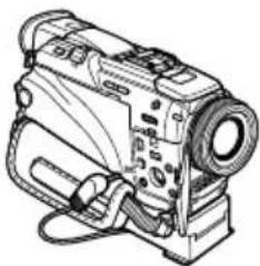
- The MPK-DVF6 can be used with the Sony Handycam Vision™ camcorder DCR-HC40/HC40E/HC30/HC30E/HC20/HC20E/HC18E/HC16E/PC109/PC109E/PC108/PC108E/PC107E/PC106E/TRV900/TRV900E/TRV890E/TRV118E/TRV116E/TRV50/TRV50E/TRV40/TRV40E/TRV30/TRV30E/TRV27/TRV27E/TRV25/TRV25E/TRV24E/TRV20/TRV20E/TRV18/TRV18E/TRV17/TRV17E/TRV16/TRV16E/TRV15/TRV15E/TRV11/TRV11E/TRV10/TRV10E/TRV9/TRV9E/TRV8/TRV8E/TRV6/TRV6E.
- Recording at depths of up to 75 meters (246 feet) is possible.
-
The following operations can be performed underwater.
-
Power on/off
- Recording start/stop
- Auto focusing on/off
– Tape photo recording - Electric zoom function
– LCD screen monitoring
Sony does not accept liability for damage to the video camera recorder, battery, etc. in the marine pack, or for the loss of prerecorded material if a water leakage caused by incorrect operation occurs.
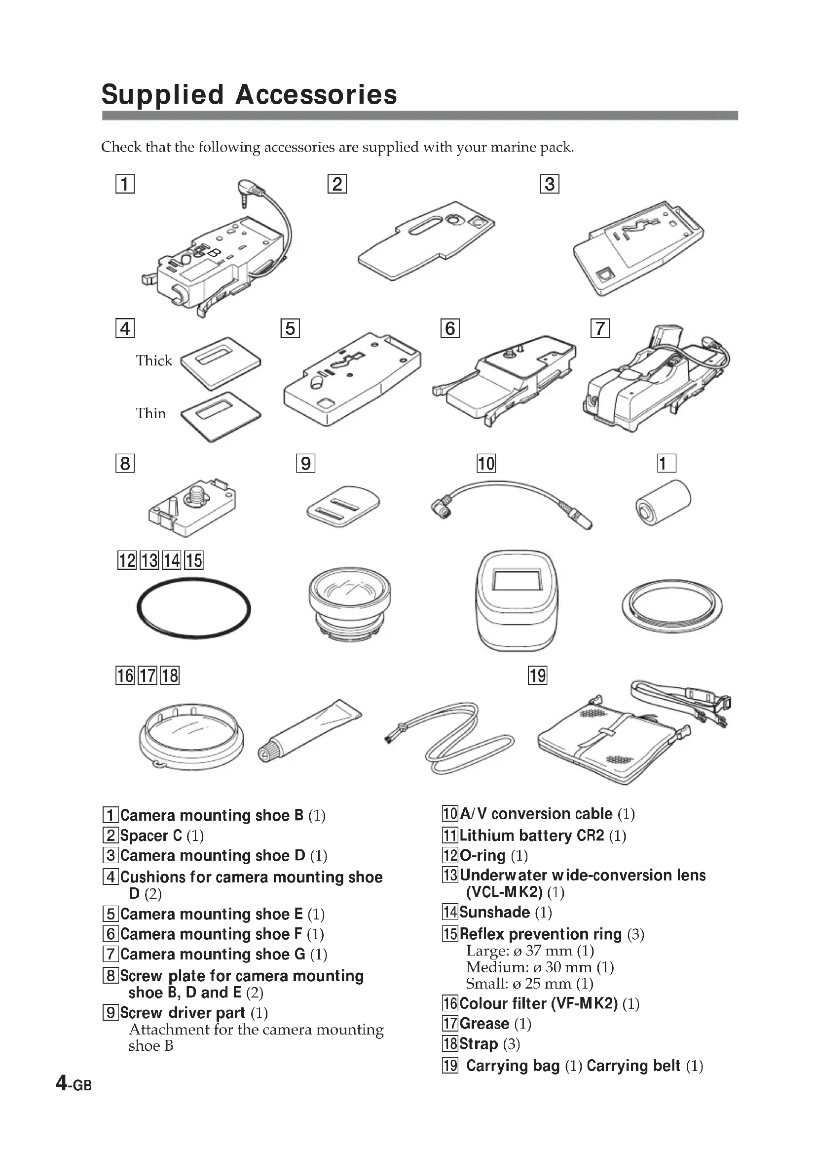
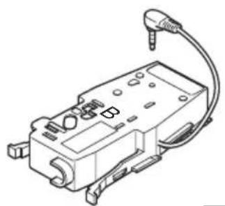
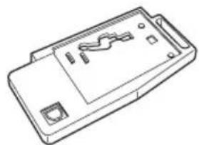
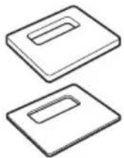
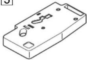
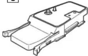
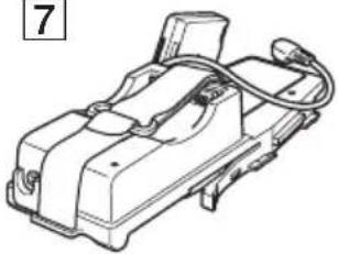
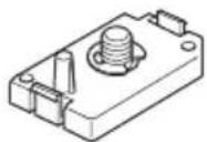
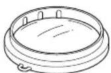
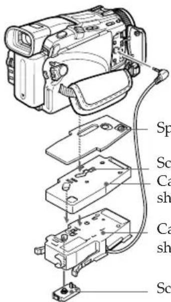
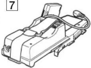
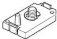
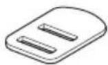
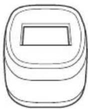
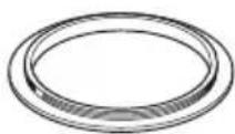
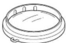
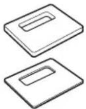
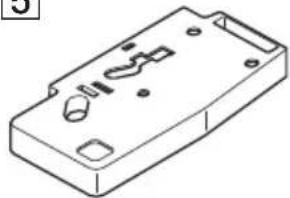
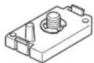
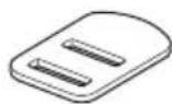
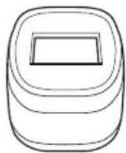
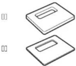
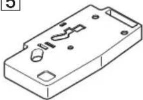
Check that the following accessories are supplied with your marine pack.
1
natural_image
Technical line drawing of a mechanical component with attached cable (no text or symbols)2

natural_image
Isometric line drawing of a mechanical part with a handle and circular cutout (no text or symbols)3
natural_image
Line drawing of a rectangular electronic device casing with internal components (no text or symbols)4
Thick
Thin
5
natural_image
Isometric line drawing of a mechanical housing component with mounting holes and internal slots (no text or symbols)6
natural_image
Technical line drawing of a mechanical component or housing (no text or symbols)7
natural_image
Technical line drawing of a mechanical device with no visible text or symbols8
9

10
1
12 13 14 15


16 17 18
natural_image
Simple line drawing of a coiled cable or wire with a connector (no text or symbols)19
natural_image
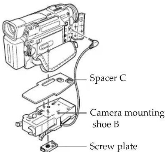
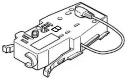
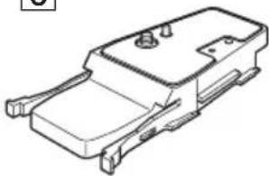
Line drawing of a portable electronic device with attached cable and connectors (no text or symbols)① Camera mounting shoe B (1)
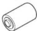
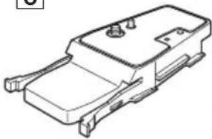
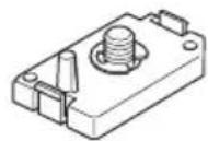
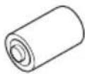
2 Spacer C (1)
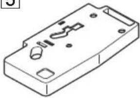
3Camera mounting shoe D (1)
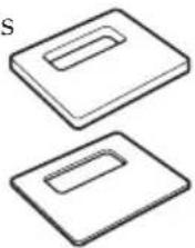
4 Cushions for camera mounting shoe D (2)
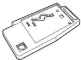
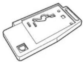
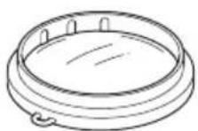
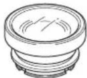
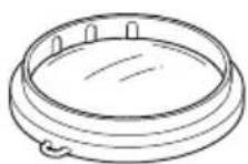
5 Camera mounting shoe E (1)
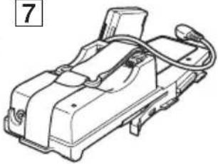
6 Camera mounting shoe F (1)
7Camera mounting shoe G (1)
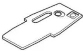
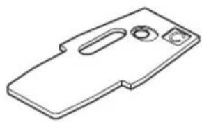
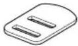
8 Screw plate for camera mounting shoe B, D and E (2)
⑨ Screw driver part (1)
Attachment for the camera mounting shoe B
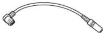
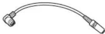
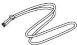
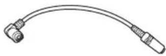
10A/V conversion cable (1)
11 Lithium battery CR2 (1)
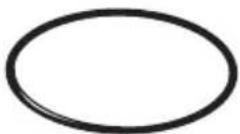
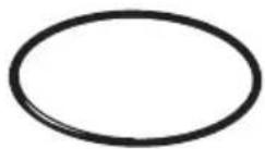
12O-ring (1)
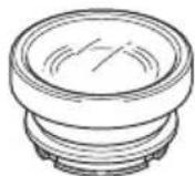
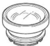
13 Underwater wide-conversion lens (VCL-MK2) (1)
14 Sunshade (1)
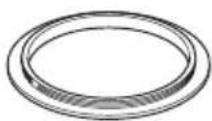
15 Reflex prevention ring (3)
Large: ø 37 mm (1)
Medium: ø 30 mm (1)
Small: ø 25 mm (1)
16Colour filter (VF-MK2) (1)
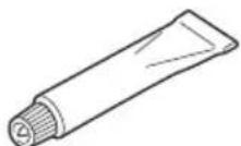
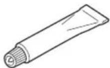
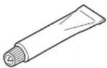
17 Grease (1)
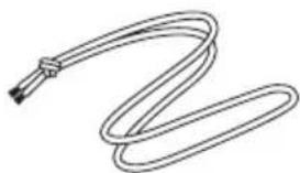
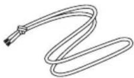
18Strap (3)
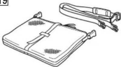
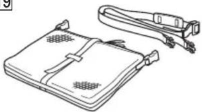
19 Carrying bag (1) Carrying belt (1)
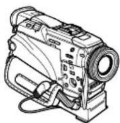
Preparing your camcorder
Before installing your camcorder in the marine pack, prepare the camcorder according to this chapter.
The procedure may be different depending on your camcorder type.
For details, please refer to the operating instructions supplied with your camcorder.
You can also install camcorder models different to the one shown in the illustration.
1 Remove the lens cap, shoulder strap, conversion lens, filter or lenshood from the camcorder.
2 Attach a fully charged battery pack.
Some models can be fitted to a mounting shoe.
3 Insert a cassette tape or "Memory Stick". Select the media you want to record onto.
4 Attach the reflex prevention ring to the lens.
for DCR-TRV50/TRV50E/TRV40/TRV40E/TRV30/TRV30E/TRV20/TRV20E/TRV9/TRV9E : 37 mm (large)
for DCR-TRV118E/TRV116E/TRV27/TRV27E/TRV25/TRV25E/TRV24E/TRV18/TRV18E/TRV17/TRV17E/TRV16/TRV16E/TRV15/TRV15E/TRV11/TRV11E/TRV10/TRV10E/TRV8/TRV8E/TRV6/TRV6E : 30 mm (medium)
for DCR-TRV900/TRV900E/TRV890E : not necessary
for DCR-HC40/HC40E/HC30/HC30E/HC20/HC20E/HC18E/HC16E/PC109/PC109E/PC108/PC108E/PC107E/PC106E : 25 mm (small)
Be sure not too tighten prevention ring.
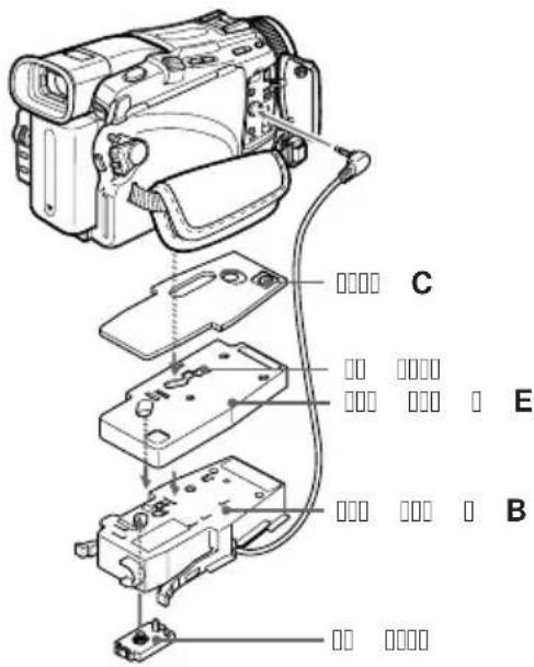
5 Attach the camera mounting shoe.
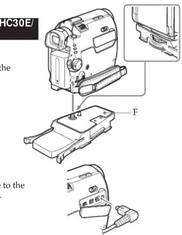
For DCR-HC40/HC40E/HC30/HC30E/HC20/HC20E/HC18E/HC16E
Use mounting shoe F and the A/V conversion cable.
① Attach mounting shoe F firmly to the camcorder.
② Connect the A/V conversion cable to the camcorder's AUDIO/VIDEO jack.
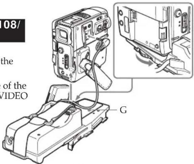
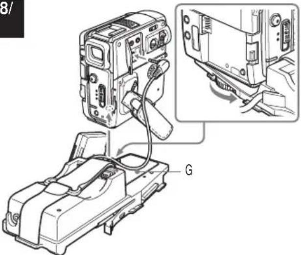
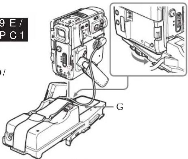
For DCR-PC109/PC109E/PC108/PC108E/PC107E/PC106E
Use mounting shoe G only.
① Attach mounting shoe G firmly to the camcorder.
② Connect the A/V connecting cable of the shoe to the camcorder's AUDIO/VIDEO jack.
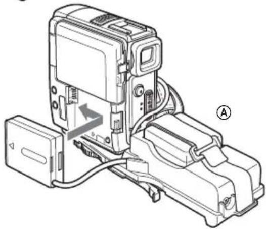
3 Attach the battery adaptor that comes with mounting shoe G to battery terminal of the camcorder.
If there is a battery installed in the camcorder, remove it.
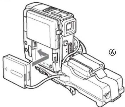
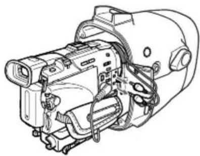
4 Attach the battery to the rear of mounting shoe G Ⓐ.
Fasten the battery firmly with the belt, as shown in the illustration.
natural_image
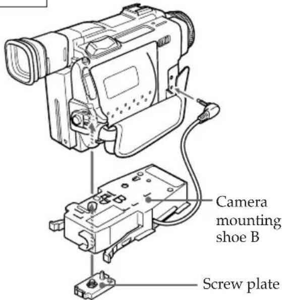
Technical line drawing of a mechanical device with labeled component (A), showing internal components and wiring (no text or symbols beyond label)For DCR-TRV900/TRV900E/TRV890E/TRV9/TRV9E
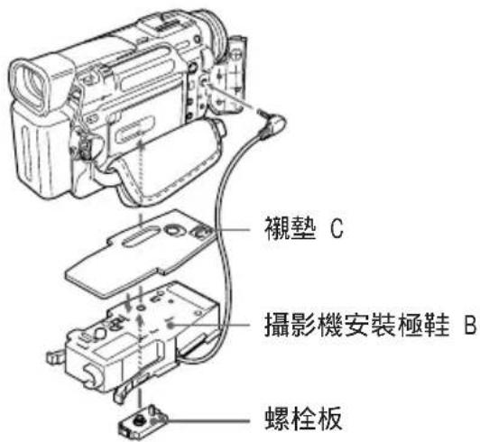
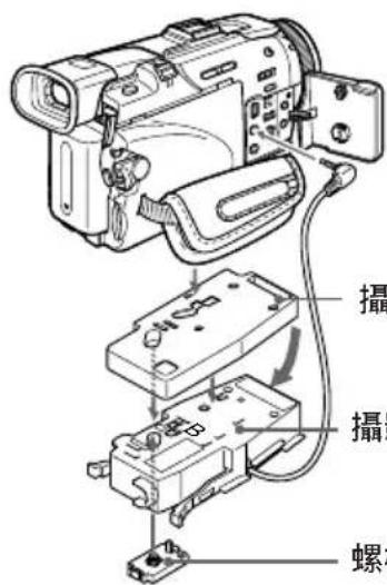
Use camera mounting shoe B and the screw plate.
Check the installing position of the screw plate for your camcorder against the table below.
| DCR- Camera mounting Shoe B | |
| TRV900/TRV900E 2 | |
| TRV890E 2 | |
| TRV9/TRV9E 1 | |

Installation position of the screw plate on the camera mounting shoe B
1 Attach the screw plate to position 1 on shoe B so that the catch on the reverse side of the shoe clicks into place.
②Fasten the screw of the screw plate to the tripod screw hole of the camcorder and tighten firmly.
3Connect the A/V connecting cable of the shoe to the camcorder's AUDIO/VIDEO jack.
For DCR-TRV10/TRV10E/TRV8/TRV8E
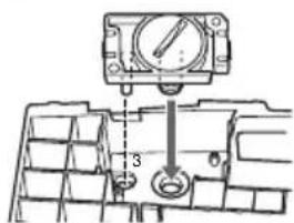
Use camera mounting shoe B, spacer C, and the screw plate.
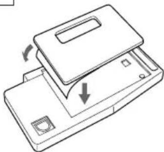
① Attach the spacer C to shoe B.
② Attach the screw plate to position 3 on shoe B so that the catch on the reverse side of the shoe clicks into place.
③ Fasten the screw of the screw plate to the tripod screw hole of the camcorder and tighten firmly.
4 Connect the A/V connecting cable of the shoe to the camcorder's AUDIO/VIDEO jack.
Installation position of the screw plate on the camera mounting shoe B
continued
For DCR-TRV30/TRV30E/TRV20/TRV20E/TRV17/TRV17E/TRV15/TRV15E/TRV11/TRV11E/TRV6/TRV6E
Use camera mounting shoe B and D, cushions for camera mounting shoe D and the screw plate.
Before attaching the camcorder
Check the cushions for camera mounting shoe D and the installing position of the screw plate for your camcorder against the table below.
| DCR- mounting | Camera Mounting | Cushion shoe B | D |
| TRV30/TRV30E 2 | 1 Thick | ||
| TRV20/TRV20E 2 | 1 Thin | ||
| TRV17/TRV17E/TRV15/TRV15E | 2 | 3 | T |
| TRV11/TRV11E/TRV6/TRV6E | 2 | 2 | T |
h i n h i n
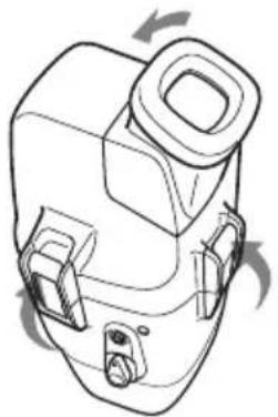
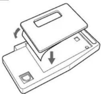
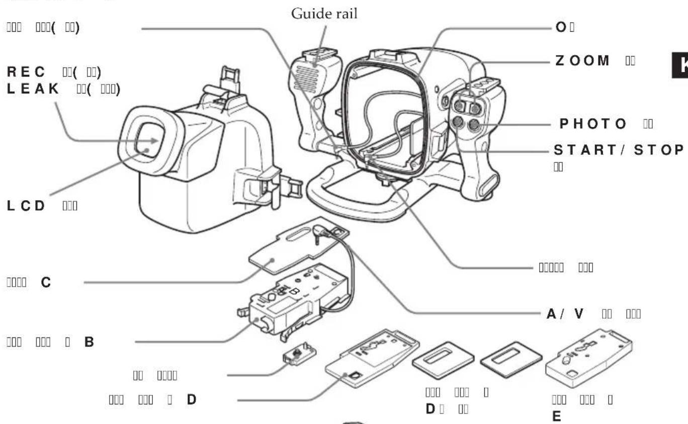
Remove the stick tape from the cushion for camera mounting shoe D. Then stick the cushion for camera mounting shoe D onto camera mounting shoe D as shown in the illustration.
natural_image
Line drawing of a device with a lid and internal components, showing directional arrows indicating movement (no text or symbols)1 Attach the screw plate to the position on shoe D so that the catch on the reverse side of the shoe D clicks into place. The installing position of the screw plate differs on your camcorder. For details, refer to the table above.
② Fasten the screw of the screw plate on shoe D to the tripod screw hole of the camcorder and tighten firmly.
③ Attach the screw plate to the position 2 on shoe B.
④ Fasten the screw of the screw plate on the shoe B to the screw hole on the shoe D of the camcorder tightly.
5 Connect the A/V connecting cable of the shoe to the camcorder's AUDIO/VIDEO jack.
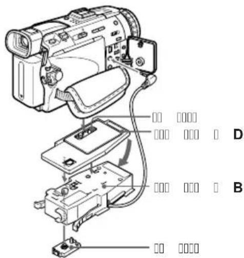
Installation position of the screw plate of the camera mounting shoe D
natural_image
Technical line drawing of a digital camera assembly with no visible text or symbolsScrew plate Camera mounting shoe D
Camera mounting shoe B
Screw plate
For DCR-TRV50/TRV50E/TRV40/TRV40E
Use camera mounting shoe B, E and the screw plate.
1 Attach the screw plate to position 1 on shoe E so that the catch on the reverse side of the shoe clicks into place.
② Fasten the screw of the screw plate on shoe E to the tripod screw hole of the camcorder and tighten firmly.
③ Attach the screw plate to position 2 on shoe B.
④ Fasten the screw of the screw plate on the shoe B to the screw hole on the shoe E of the camcorder tightly.
5Connect the A/V connecting cable of the shoe to the camcorder's AUDIO/VIDEO jack.
natural_image
Mechanical assembly diagram showing internal components with no visible text or symbolsInstallation position of the screw plate on the camera mounting shoe E
Camera mounting shoe E
Camera mounting shoe B
Screw plate
For DCR-TRV118E/TRV116E/TRV27/TRV27E/TRV25/TRV25E/TRV24E/TRV18/TRV18E/TRV16/TRV16E
Use camera mounting shoe B and E, spacer C, and the screw plate.
1 Attach the spacer C to shoe E. Attach the screw plate to position 2 on shoe E so that the catch on the reverse side of the shoe clicks into place.
② Fasten the screw of the screw plate on shoe E to the tripod screw hole of the camcorder and tighten firmly.
③ Attach the screw plate to position 2 on shoe B.
④ Fasten the screw of the screw plate on the shoe B to the screw hole on the shoe E of the camcorder tightly.
5Connect the A/V connecting cable of the shoe to the camcorder's AUDIO/VIDEO jack.
Installation position of the screw plate on the camera mounting shoe B
Spacer C
Screw plate Camera mounting shoe E
Camera mounting shoe B
Screw plate
Now you are ready to install the camcorder to the marine pack. Be sure to check that the camera mounting shoe is attached to the camcorder tightly before you install the camcorder to the marine pack.
6 Prepare to record.
① Set the POWER switch to CAMERA.
② Set COMMANDER to ON in the menu settings.
③ Cancel the following functions: BACK LIGHT, NIGHTSHOT, PROGRAM AE, flash and Picture effect.
④ Set the FOCUS switch to AUTO.
⑤ Set DISPLAY to V-OUT/LCD in the menu settings and press the DISPLAY button on your camcorder before installing the marine pack.
* If your camcorder has REC LAMP in the menu settings, set it to OFF. By using this function, the light of the lamp is not reflected in the lens. For details, please refer to the operating instructions supplied with your camcorder.
Preparing the marine pack (installing the battery)
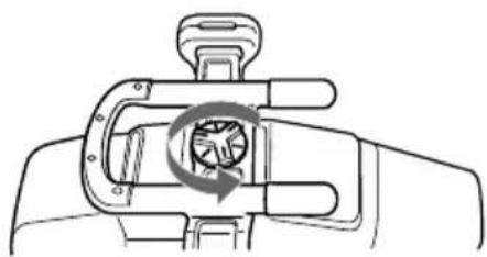
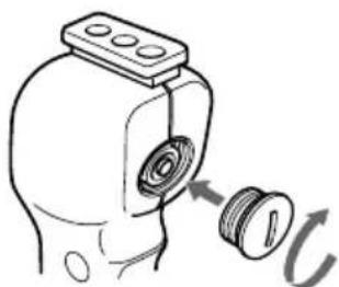
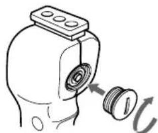
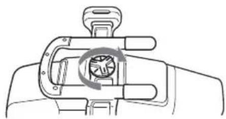
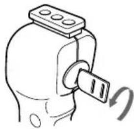
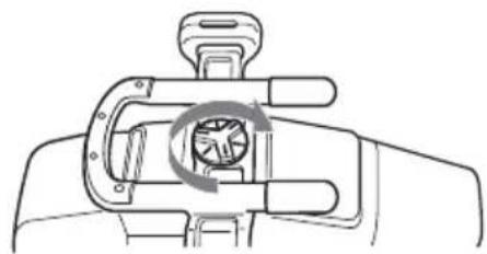
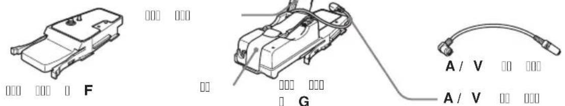
1 Remove the grip.
Undo the screw on the bottom side of the marine pack.
natural_image
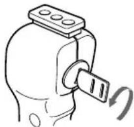
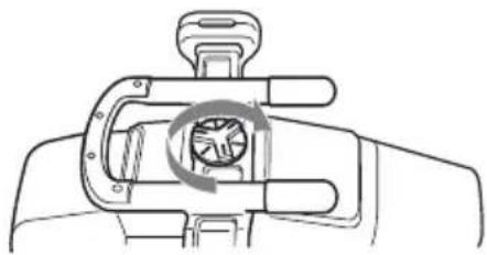
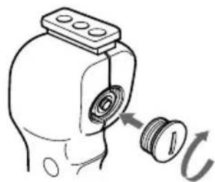
Diagram of a hand holding a mechanical component with a circular arrow indicating rotation (no text or symbols)2 Insert the lithium battery into the grip.
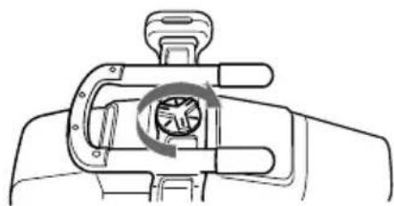
① Remove the screw with the supplied screw driver.
natural_image
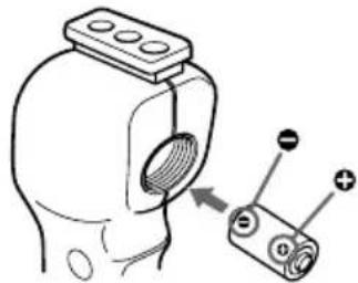
Simple line drawing of a mechanical component with a knob and rotating arrow (no text or symbols)②Insert the supplied lithium battery (CR2, · 1) with the polarity positioned correctly as indicated on the grip.
natural_image
Diagram of a mechanical component with a threaded part and a separate cylindrical component with labeled terminals (no text or symbols present)③Fasten the screw tightly.
natural_image
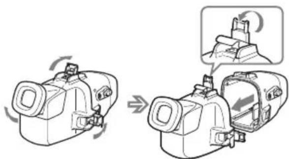
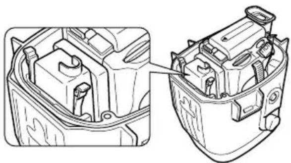
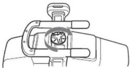
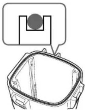
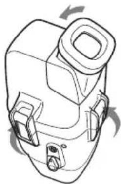
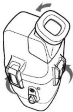
Technical line drawing of a mechanical component with a threaded fitting and a circular arrow indicating rotation (no text or symbols)3 Unfasten the 3 latches and open the marine pack.
If you lift the metal part in the direction of the finder when the latches are open, the latches will stop.
natural_image
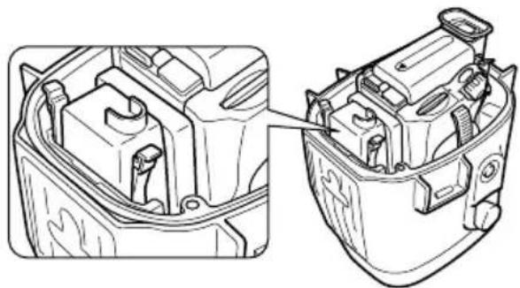
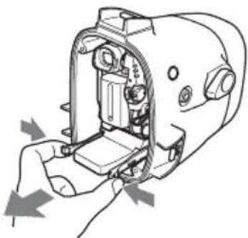
Diagram showing a device being processed with a magnified view of the internal components (no text or symbols present)4 Insert the batteries (optional) into the LCD monitor battery compartment. Use four AA alkali dry batteries or four Ni-MH batteries.
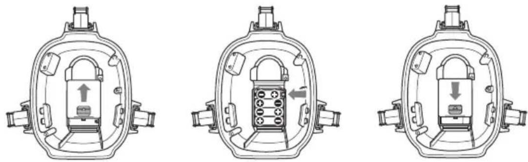
Use new dry batteries.
If you use rechargeable dry batteries, fully charge it before use.
Notes
- Be sure to use four batteries of the same type.
- Be sure to confirm the poles of the batteries. Inserting the batteries with the poles in the wrong direction may cause leakage or ruptures.
About the LCD monitor
• Install the camcorder to the marine pack and set the POWER switch to ON to make images appear on the LCD screen.
- The remaining battery time indicator displayed on the LCD monitor refers to remaining time of the camcorder battery time, not the remaining time of the LCD monitor battery.
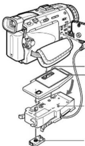
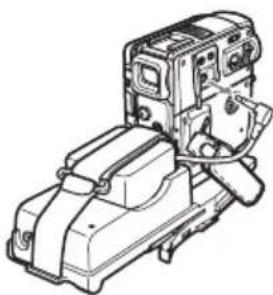
Installing the camcorder to the marine pack
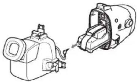
For DCR-HC40/HC40E/HC30/HC30E/HC20/HC20E/HC18E/HC16E
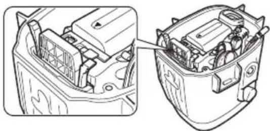
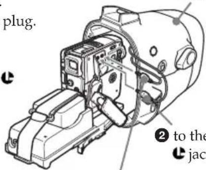
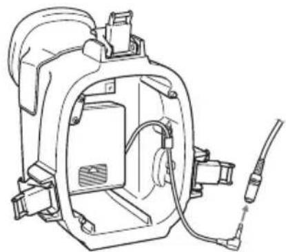
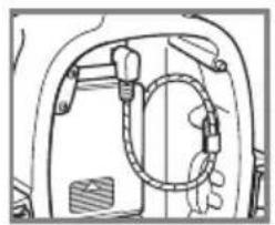
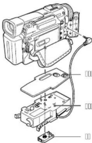
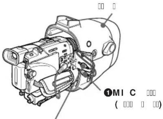
1 Install the camcorder to the marine pack. Connect the remote plug and the microphone plug.
①Connect the microphone plug to the MIC jack (plug in power).
②Connect the remote plug to the LANC jack.
front shell
natural_image
Technical line drawing of a mechanical device with internal components and wiring (no text or symbols)① to the MIC jack (plug in power)
② to the LANC Jack
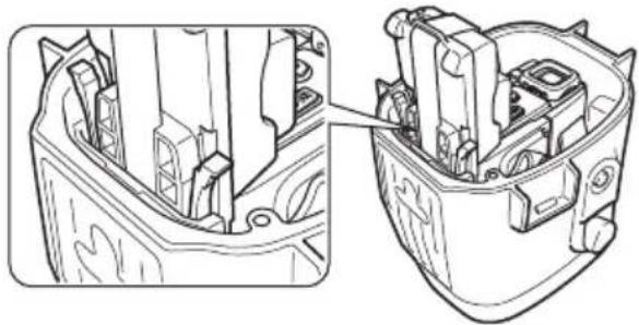
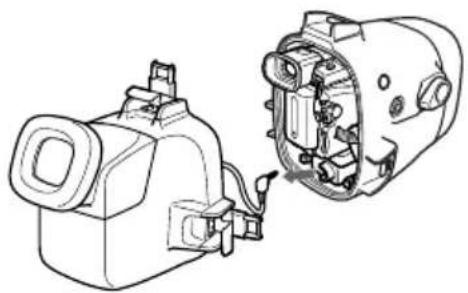
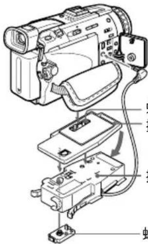
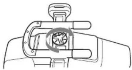
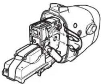
2 Insert the camcorder until the mounting shoe clicks into place.
natural_image
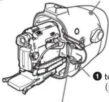
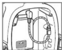
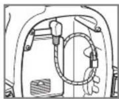
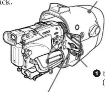
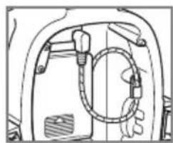
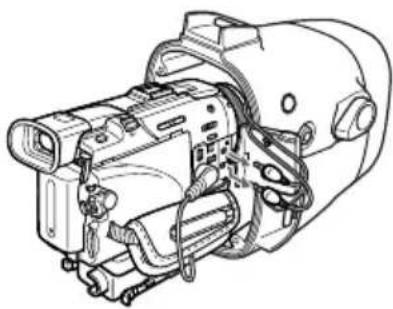
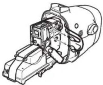
Technical line drawing of a car engine compartment showing internal components and wiring (no text or symbols)3 Connect the monitor cord to the A/V conversion cable attached to the camcorder.
natural_image
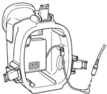
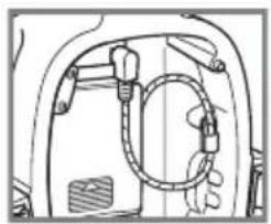
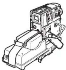
Technical line drawing of a vehicle rear panel with hoses and a handle (no text or symbols)The cords are placed in the plug holders of the marine pack at the factory. Pull the plugs out of the holders when in use.
natural_image
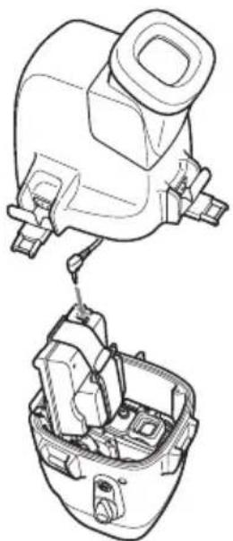
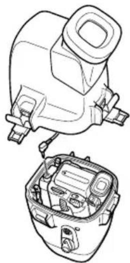
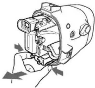
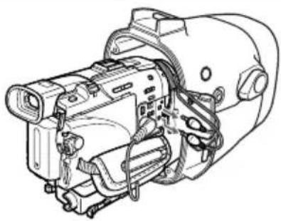
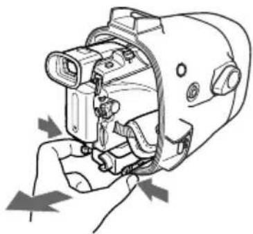
Technical line drawing of a mechanical device with no visible text or symbols4 Attach the front shell to the rear shell. Hold both shells firmly and fasten the 3 latches securely.
Take care not to pinch the remote, microphone, and monitor cords. If this happens water may leak in. For details on handling the O-ring, see page 29.
Take care not to pinch the cords.

natural_image
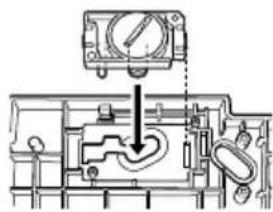
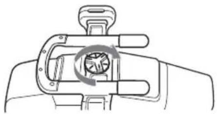
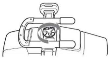
Line drawing of a mechanical device with ports and a handle (no text or symbols)5 Attach the grip. Fasten the screw tightly.
natural_image
Diagram of a hand holding a mechanical device with a circular arrow indicating rotation (no text or symbols)Now you have finished the preparations.
Be sure to check that the equipment operates correctly and that there is no water leakage before you dive (see page 20).
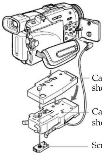
For DCR-PC109/PC109E/PC108/PC108E/PC107E/PC106E
1 Install the camcorder to the marine pack.
Connect the remote plug and microphone plug.
①Connect the microphone plug to the MIC jack (plug in power).
②Connect the remote plug to the LANC jack.
front shell
to the LANC
jack
① to the MIC jack (plug in power)
2 Insert the camcorder until the mounting shoe clicks into place.
natural_image
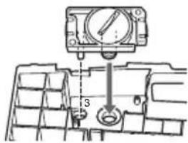
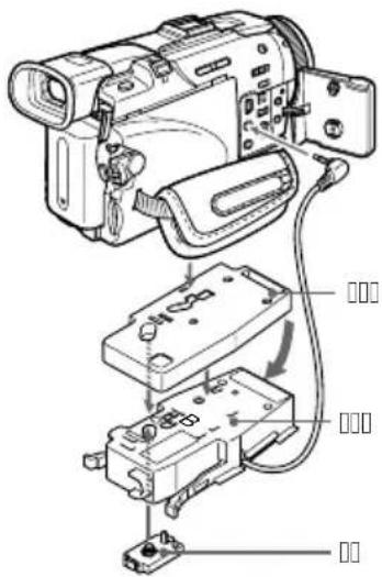
Technical line drawing of a mechanical component with internal parts and mounting holes (no text or symbols)3 Connect the monitor cord to the jack of camera mounting shoe G.
natural_image
Technical line drawing of a car interior showing hoses and a handle (no text or symbols)The cords are placed in the plug holders of the marine pack at the factory. Pull the plugs out of the holders when in use.
natural_image
Technical line drawing of a mechanical assembly with no visible text or symbols4 Attach the front shell to the rear shell. Hold both shells firmly and fasten the 3 latches securely. Take care not to pinch the remote, microphone, and monitor cords. If this happens water may leak in. For details on handling the O-ring, see page 29. Take care not to pinch the cords.
natural_image
Line drawing of a mechanical device with no visible text or symbols5 Attach the grip. Fasten the screw tightly.
natural_image
Line drawing of a mechanical device with a circular arrow indicating rotation or motion (no text or symbols)Now you have finished the preparations. Be sure to check that the equipment operates correctly and that there is no water leakage before you dive (see page 20).
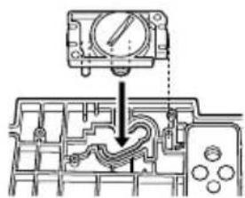
For DCR-TRV900/TRV900E/TRV890E/TRV118E/TRV116E/TRV50/TRV50E/TRV40/TRV40E/TRV30/TRV30E/TRV27/TRV27E/TRV25/TRV25E/TRV24E/TRV20/TRV20E/TRV18/TRV18E/TRV17/TRV17E/TRV16/TRV16E/TRV15/TRV15E/TRV11/TRV11E/TRV10/TRV10E/TRV9/TRV9E/TRV8/TRV8E/TRV6/TRV6E
1 Install the camcorder to the marine pack.
Connect the remote plug and the microphone plug.
①Connect the microphone plug to the MIC jack (plug in power).
②Connect the remote plug to the LANC jack.
front shell
natural_image
Technical line drawing of a mechanical assembly with no visible text or symbols① to the MIC jack (plug in power)
② to the LANC Jack
2 Insert the camcorder until the mounting shoe clicks into place.
natural_image
Technical line drawing of a mechanical component with internal parts, showing two views (top and side), no text or symbols present.3 Connect the monitor cord to the jack of camera mounting shoe B.
natural_image
Technical line drawing of a mechanical component with hoses and connectors (no text or symbols)The cords are placed in the plug holders of the marine pack at the factory. Pull the plugs out of the holders when in use.
natural_image
Technical line drawing of a mechanical device with internal components (no text or symbols)4 Attach the front shell to the rear shell. Hold both shells firmly and fasten the 3 latches securely. Take care not to pinch the remote, microphone, and monitor cords. If this happens water may leak in. For details on handling the O-ring, see page 29.

natural_image
Line drawing of a mechanical device with no visible text or symbols5 Attach the grip. Fasten the screw tightly.

natural_image
Diagram of a hand holding a mechanical device with a circular arrow indicating rotation (no text or symbols)Now you have finished the preparations. Be sure to check that the equipment operates correctly and that there is no water leakage before you dive (see page 20).
Before diving
Check for water leakage.
Check that the equipment operates correctly and that there is no water leakage at a depth of about one meter (3 feet) before you dive deeper.
Take care not to expose the equipment to salty air. Do not drop water on the equipment.
Do not open the marine pack underwater or on the beach. Preparations such as installing and checking the equipment should be done in a place with low humidity and no salty air.
Check the following points again before you dive.
□Be sure to fully charge the battery pack for the camcorder.
Be sure that the dry battery for the monitor is not old.
- We recommend you use battery packs with a large capacity and prepare a spare battery and dry batteries.
□Be sure that a video tape and "Memory Stick" have enough left.
☐Check that there are no scratches or cracks on the O-ring.
□Make sure there is no dust, sand, or hair between the front shell and the rear shell.
□Be sure that the lithium battery has enough power.
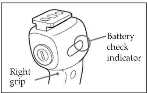
- If the remaining battery capacity is enough, when you press the ZOOM, PHOTO, or START/STOP button, the Flash lamp lights up. Check this indicator as a criterion. If the flash lamp does not light, exchange for a new one. We suggest that you prepare spare ones.
Conditions of underwater recording
Recording underwater is different from recording on land because it is affected by the clarity, depth of the water, and the light conditions. The following are hints for good recording underwater.
Best time for recording
The best recording time is from 10:00 a.m. to 2:00 p.m. When the sun is at its highest, optimum results can be obtained.
To record is in dark places as the sun does not reach or at night, use a powerful underwater video light.
Subject size underwater
Since the refractive index underwater is higher than that in air, objects appear 1/4 closer, and therefore larger. This phenomenon affects the lens on the camcorder as well as human the eye. Using the supplied wide-conversion lens is recommended.
Operate the camera with slow and stable motions
When recording, keep your body stable.
An unstable shot will be magnified on the TV screen.
Move the camcorder as slowly as possible. Since most of the objects underwater move, you can record a good shot without moving the camcorder too much.
Note on recording underwater
Be sure to follow the safety rules for diving, such as diving period and depth.
Now you are ready for underwater recording.
When you dive with the camcorder, dive slowly, paying attention to the surrounding environment. Be careful not to strike the marine pack against Rocks or Reef, etc.
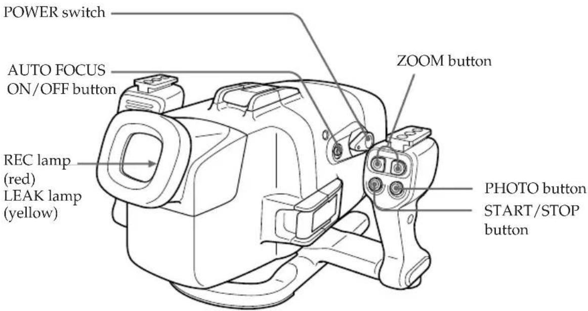
1 Set the POWER switch to ON.
The camcorder turns on and a picture appears on the LCD monitor.
2 Press START/STOP button to start recording.
The REC lamp (red) lights up during recording.
To stop recording, press START/STOP button again.
To zoom
Press ZOOM button.
Press T for telephoto (subject appears closer) and W for wide-angle (subject appears further away). You cannot change the zooming speed of the camcorder.
Recording a still image
You can record a still image on a tape or "Memory Stick" by pressing PHOTO button. (Some models, however, can only record onto a tape, even if a "Memory Stick" can be inserted.)
Note that pressing PHOTO button lightly does not allow you to check the recorded image. For more details, refer to the operating instructions supplied with your camcorder.
To keep a subject in focus
Press AUTO FOCUS ON/OFF button to set it to OFF. You can still keep the subject in focus even if fish swim between the camcorder and the subject. Press AUTO FOCUS ON/OFF button again to set the camcorder to auto focus mode.
Note
Do not cover the control emitter or detector with your finger as the remote control signal for operations is transmitted from the grip to the marine pack.
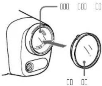
Attaching the supplied accessories
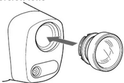
Attaching the supplied wide-conversion lens
As objects appear 1/4 closer and therefore larger, the wide-conversion lens is recommended when you want to take pictures of wide areas. Note however, that objects will appear smaller.
Note
This supplied wide-conversion lens is to be used only underwater.
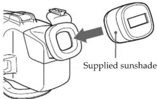
Using the supplied sunshade
The supplied sunshade reduces glare from the LCD monitor.
natural_image
Diagram of a device with a circular component and a separate cylindrical component, no text or symbols presentAttach the wide-conversion lens until it fits firmly.
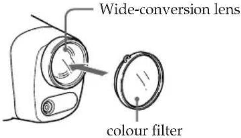
Attaching the supplied colour filter
When using the supplied colour filter, attach it on top of the wide-conversion lens.
Water absorbs light, especially red light, so that objects in deep water are seen bluish. The colour of objects is affected by the clarity of the water. To record in natural colour, use the supplied colour filter.
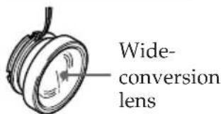
You can attach and remove the wide-conversion lens, sunshade, and colour filter underwater.
If the image on the LCD screen is not clear because of air between these accessories and the marine pack, reattach them underwater.
Attaching the supplied strap
Attach the strap as the shown. Attach the supplied straps to prevent loss of these accessories when removing them both on land and underwater. Attach the straps to the grip of the marine pack.


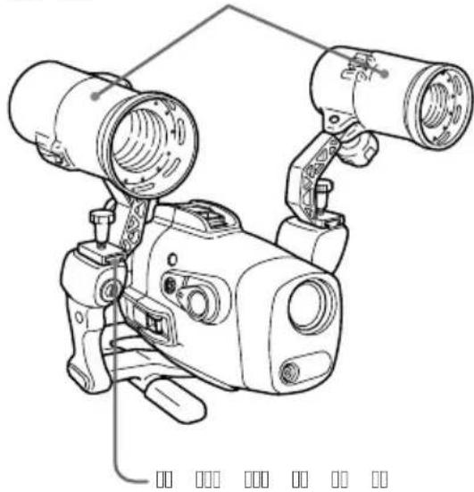
Using the underwater video light (optional)
In deep water or under rocks where direct sunlight does not reach, recording with underwater video lights is recommended.
You can attach these video lights to the video light shoes on the upper part of both grips.
Underwater video lights such as the Sony HVL-ML20M (optional)
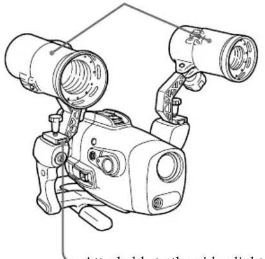
natural_image
Line drawing of a vintage camera with two lenses and a mounted device (no text or symbols)Attachable to the video light shoes on both sides
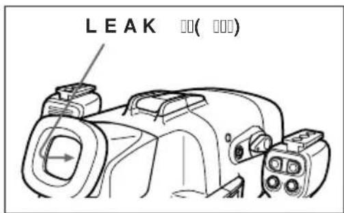
Water leakage
The marine pack is designed to be waterproof, however if water happens to leak in, the LEAK lamp (yellow) flashes.
In such a case, remove the marine pack from the water as soon as possible, keeping it horizontal. Be sure to surface following the safety rules for diving.
Dry the marine pack with a soft cloth and then open it.
To switch off the lamp, disconnect the remote control cable.
Check the cause of the leak.
LEAK lamp (yellow)
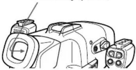
natural_image
Line drawing of a DSLR camera with attached display unit (no text or symbols)If the camcorder is wet, take it to the nearest Sony dealer immediately.
We recommend you purchase property damage insurance for underwater materials in case of emergency.
After using
• After recording in the sea, submerge the marine pack in tap water or fresh water for about 30-60 minutes before undoing the latches to completely remove any salt from the marine pack unit, filter, and wide-conversion lens.
- When your camcorder is to be used near the sea for a long time, we recommend that it be checked periodically by the nearest Sony dealer.
Before opening the marine pack, rinse it with fresh water and dry with a soft cloth. When you open the marine pack, make sure you are dry. And take care that no water drips from your wet suit.
For DCR-HC40/HC40E/HC30/HC30E/HC20/HC20E/HC18E/HC16E
1 Remove the grip.
2 Unfasten 3 latches and open the marine pack.
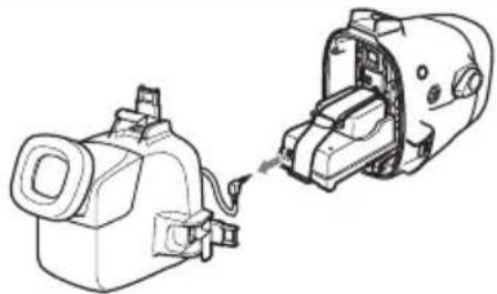
3 Disconnect the monitor cord from the A/V conversion cable.
natural_image
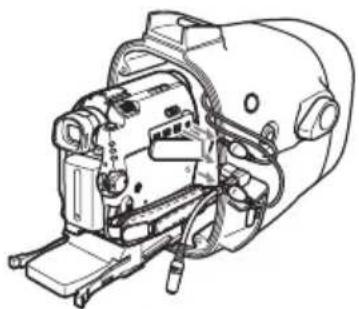
Technical line drawing of a mechanical device with attached wires and components (no text or symbols)4 Take the camcorder out of the front shell. Hold the camera mounting shoe by the knobs and extract the camcorder. When you open the marine pack, do not pull the monitor plug cord by force.
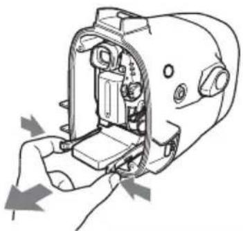
natural_image
Diagram of a hand inserting a device into a device housing (no text or symbols visible)5 Disconnect the remote plug, the microphone plug and the A/V conversion cable.
natural_image
Technical line drawing of a mechanical device with no visible text or symbols6 Remove the mounting shoe from the camcorder.
7 Remove the batteries from the LCD monitor battery compartment.
For DCR-PC109/PC109E/PC108/PC108E/PC107E/PC106E
1 Remove the grip.
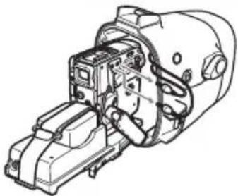
2 Unfasten 3 latches and open the marine pack. Disconnect the monitor cord from the camera mounting shoe G.
natural_image
Technical line drawing of a sewing machine with side and top views (no text or symbols)3 Take the camcorder out of the front shell. Hold the camera mounting shoe by the knobs and extract the camcorder. When you open the marine pack, do not pull the monitor plug cord by force.
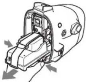
natural_image
Technical line drawing of a mechanical device with internal components and directional arrows indicating movement (no text or symbols)4 Disconnect the remote plug and the microphone plug.
natural_image
Technical line drawing of a mechanical assembly with no visible text or symbols5 Disconnect the A/V connecting cable of camera mounting shoe G from the AUDIO/VIDEO jack.
natural_image
Technical line drawing of a mechanical device with no visible text or symbols6 Remove the battery adaptor from the camcorder before removing the mounting shoe. Also remove the battery attached to the rear of mounting shoe G.
7 Remove the batteries from the LCD monitor battery compartment.
For DCR-TRV900/TRV900E/TRV890E/TRV118E/TRV116E/TRV50/TRV50E/TRV40/TRV40E/TRV30/TRV30E/TRV27/TRV27E/TRV25/TRV25E/TRV24E/TRV20/TRV20E/TRV18/TRV18E/TRV17/TRV17E/TRV16/TRV16E/TRV15/TRV15E/TRV11/TRV11E/TRV10/TRV10E/TRV9/TRV9E/TRV8/TRV8E/TRV6/TRV6E
1 Remove the grip.
2 Unfasten 3 latches and open the marine pack. Disconnect the monitor cord from the camera mounting shoe B.
natural_image
Technical line drawing of a mechanical device with two views: top shows internal components, bottom shows external housing (no text or symbols)3 Take the camcorder out of the front shell. Hold the camera mounting shoe by the knobs and extract the camcorder. When you open the marine pack, do not pull the monitor plug cord by force.
natural_image
Diagram of a hand operating a mechanical device with arrows indicating motion (no text or symbols present)4 Disconnect the remote plug and the microphone plug.
natural_image
Technical line drawing of a mechanical assembly (no text or symbols visible)5 Disconnect the A/V connecting cable of camera mounting shoe B from the AUDIO/VIDEO jack.
natural_image
Line drawing of a vintage camera with attached mechanical components (no text or symbols)6 Remove the camera mounting shoe with the screw driver.
Undo the screw of the screw plate and remove the camera mounting shoe from the camcorder.
7 Remove the batteries from the LCD monitor battery compartment.
After using the marine pack
Insert the A/V connecting cable plug to the plug holder of the camera mounting shoe B.
natural_image
Technical line drawing of a mechanical component with no visible text or symbolsWhat is an O-ring?
- An O-ring is part of the water-proof packing that is used on underwater cameras, watches, and other diving equipments.
- The O-ring acts to preserve the waterproof qualities of the marine pack and other equipments.
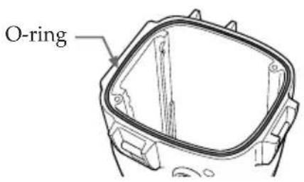
How the O-ring waterproofs
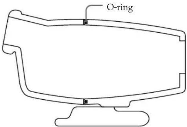
The surface of the O-ring contacts the rubber to prevent water from entering the gap.
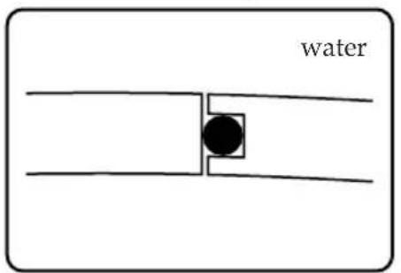
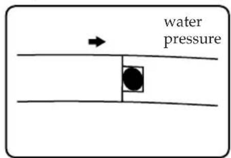
When water pressure acts on the O-ring, the contact surface area of the O-ring expands to increase the force acting on the groove on the marine pack.
O-ring maintenance is very important. If O-ring maintenance is not followed according to instructions, this might cause a water leak, and cause the marine pack to sink. The surface of the O-ring contacts the entire rubber evenly to prevent water from entering the gap.
Handling the O-ring
Set the O-ring in place
Avoid setting the O-ring in dusty or sandy locations.
1 Remove the O-ring.
Do not use pointed or metal objects to remove the O-ring. These objects might scratch or damage the marine pack groove or O-ring.
2 Inspect the O-ring.
- Fully check the following, and wipe off with a soft cloth or tissue paper. - Check for any dirt, grains of sand, hair, dust, salt, thread scraps, etc. - Check for any old grease.
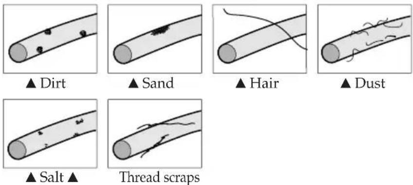
- Lightly run your fingertip around the O-ring to check for any unapparent dirt.
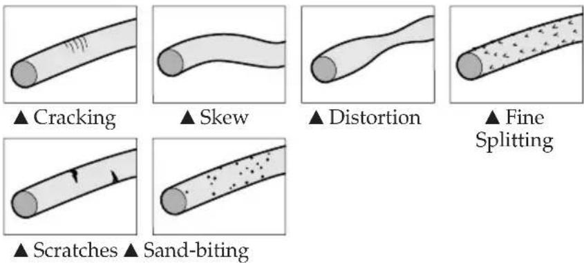
• After wiping the O-ring, take care to prevent any cloth or tissue paper fibres from remaining on the O-ring. - Check the O-ring for cracking, skew, distortion, fine splitting, scratches, sand-biting, etc. Replace cracked or scratched O-rings.
3 Inspect the O-ring groove.
Grains of sand or hardened salt sometimes get into the groove. Carefully remove them by blowing with an air spray or by wiping them with a cotton wool bud. Prevent fibre scraps from the cotton wool bud from entering inside.
4 Also, inspect the contacting surface on the other side of the O-ring in the same way.
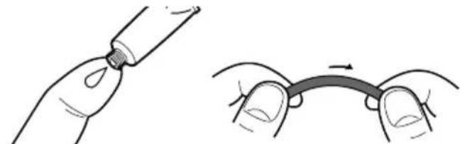
5 Apply a coating of grease to the O-ring.
natural_image
Illustration showing a hand holding a tube and a close-up of a curved object with arrows indicating motion (no text or symbols)- Apply a small drop of grease onto the O-ring and evenly coat the entire surface of the O-ring with the end of your finger.
- Do not use paper or cloth as fibre may stick to the O-ring.
- Make sure that a thin coating of grease is applied to the surface of the O-ring at all times. Grease protects the O-ring, and prevents wear.
• After you have applied a small drop of grease onto the O-ring, set the O-ring immediately. Do not leave the greased O-ring on a desk or other surfaces.
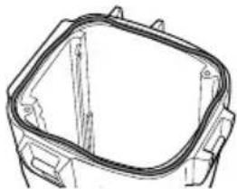
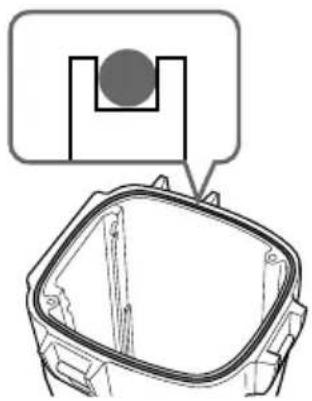
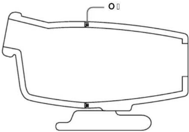
6 Place the O-ring in the groove on the marine pack.
Place the O-ring evenly in its groove paying attention to the following points:
- Is there any dirt on the O-ring?
- Is the O-ring twisted?
- Do not pull the O-ring.
- Is the O-ring protruding?
natural_image
Technical line drawing of a mechanical component with no visible text or symbols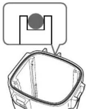
natural_image
Technical line drawing of a mechanical component with a circular feature and a magnified inset (no text or symbols)Bad example Good example
Final check
After you have fitted in the O-ring, check it again for the following:
- Is the O-ring twisted?
- Is there any dirt on the O-ring?
- Is the O-ring protruding?
- Are there any cracking or distortion on the O-ring?
How to check for water leaks
After you have replaced the O-ring, close the marine pack before you insert the equipment you are using. Immerse the marine pack for about three minutes in water to a depth of about 15 cm, and check for water leaks.
CAUTION
When you have taken photos on a sandy sea bottom or have placed the camera on the sand, remove the O-ring and check for water leaks.
Be sure to take a spare O-ring with you. This facilitates replacement even if O-ring trouble occurs where you are taking photos.
Maintenance
After you have finished using an O-ring
• After you have used the marine pack, be sure to perform the following:
- Wash the marine pack with fresh water with the buckle closed to remove salt or sand.
- Insert the marine pack in fresh water for about 30 minutes with the buckle closed. If salt is left on the marine pack, metal parts and the O-ring might be damaged, and cause water leaks.
- When sun oil is stuck to the marine pack, wash off with lukewarm water. If sun oil is left on the marine pack, the surface of the marine pack might become discoloured or become damaged.
- Wipe the inside of the marine pack with a soft, dry cloth. Do not wash with water.
- Remove the O-ring each time that you have finished using it, and check it. If the marine pack is dried with sea water still in the O-ring groove, salt crystals form, and might impair the O-ring's functions.
- Do not use thinner, benzene, alcohol or other solvents as they will damage the surface finish.
Storing O-rings
- Prevent dust from sticking to O-rings.
- Apply a thin coating of grease to the O-ring, set it in the groove, and store in a well-ventilated location. Do not close the buckle.
- Avoid storing O-rings in hot, cold or humid locations, and placing in naphthalene or camphor. These locations and solutions will damage the materials.
How to store O-rings
- To maintain the O-ring's functions, avoid storing them in hot locations or in the direct sunlight.
- Do not place the spare O-ring under heavy objects. Doing so might deform the O-ring.
O-ring life
Replace the O-ring with a new one after one year of use.
Even if the O-ring is not cracked or scratched, deformation or wear reduces the waterproof qualities of the O-ring. Replace the O-ring with a new one if cracking, skew, distortion, fine splitting, scratches, sand-biting, etc. is found.
Grease
Use the supplied grease. Using other manufacturer's grease will damage the O-ring, and cause water leaks.
O-ring and grease
You can obtain O-rings and grease at your nearest Sony dealer.
O-ring (model No. 3-977-362-01)
Grease (model No. 3-071-370-01)
After using
The metal parts will rust and the movement of the operation switches will be impaired if you leave salt water on the marine pack. If sea water enters through scratches in the coating, the salt can corrode the metal parts of the marine pack unit and cause the coating to peel off. After recording in the sea, submerge the marine pack in tap water or fresh water for about 30 minutes before undoing the buckles to completely remove any salt from the marine pack unit, filter, and wide-conversion lens.
After washing, wipe any water from the inside of the marine pack and the loaded video camcorder with a soft dry cloth.
* Always follow the above precautions when you use the marine pack.
When you open the marine pack or exchange the battery pack of the grip, take care that no water drips from your wet suit or hair.
Do not leave the marine pack under direct sunlight for a long period of time, otherwise the temperature in the marine pack may rise and the equipment inside may be damaged. If you cannot avoid leaving the marine pack under direct sunlight, be sure to cover the marine pack with a towel or other protection.
When you store the marine pack
Coat the O-ring slightly with the supplied grease, and put it in the groove correctly. Join the front and rear shells then put it in a cool and dry place without fastening the buckles.
Avoid storing the marine pack in a very hot, cold, or humid place, or together with naphthalene or camphor, as these conditions might damage the unit.
On transportation
When transporting the marine pack, be sure to remove your camcorder from it. Otherwise this might damage the unit.
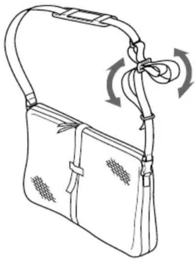
Note
When you use the supplied carrying bag, attach the supplied carrying belt and adjust the length of the belt.
Avoid rough handling or a shock. We recommend covering the marine pack with a towel or other protection.
natural_image
Line drawing of a handbag with straps and a belt, showing rotational motion (no text or symbols)Identifying parts and controls
Material
Aluminum alloy, glass, plastic (ABS, PC)
Waterproofing
O-ring, 3 latches
Usable depth
Up to 75 m (246 feet)
Underwater microphone
Condenser microphone (monaural)
Controllable function
Power on/off, recording start/stop, auto focus on/off, power zooming, tape photo recording
Dimensions
Approx. 312 · 212 · 318 mm (w/h/d) (12 3/8 · 8 3/8 · 12 5/8 in.)
Mass
Approx. 4.4 kg (9 lb 11 oz) (the unit only)
Supplied accessories
Camera mounting shoe B, D, E, F, G (1 each)
Spacer C (1)
Cushions for camera mounting shoe D (2)
Screw plate (2)
Screw driver part (1)
A/V conversion cable (1)
Wide-conversion lens (1)
Colour filter (1)
Lithium battery CR2 (1)
Grease (1)
O-ring (1)
Sunshade (1)
Reflex prevention ring (3)
Strap (3)
Carrying bag (1)
Carrying belt (1)
Operating instructions (1)
Warranty (1)
Recommended accessory
Underwater video light HVL-ML20M
Design and specifications are subject to change without notice.
Table des matières
natural_image
Technical line drawing of a mechanical component with attached cable (no text or symbols)2

natural_image
Isometric line drawing of a 3D mechanical part with two circular holes and a rectangular body (no text or symbols)3

natural_image
Line drawing of a device casing with internal components and mounting holes (no text or symbols)4
Epais
5
natural_image
Isometric line drawing of a mechanical housing component with mounting holes and internal slots (no text or symbols)6
natural_image
Technical line drawing of a mechanical component or housing (no text or symbols)7
natural_image
Technical line drawing of a mechanical device with no visible text or symbols8

9

10

1
12 13 14 15


16 17 18

19

natural_image
Simple line drawing of a coiled cable or wire with a connector (no text or symbols)
natural_image
Line drawing of a portable electronic device with attached cable and ventilation slots (no text or symbols)natural_image
Cross-sectional diagram of a mechanical assembly with no visible text or symbolsnatural_image
Technical line drawing of a digital camera assembly with no visible text or symbolsnatural_image
Line drawing of a device with arrows indicating process flow (no text or symbols)natural_image
Technical diagram of a mechanical assembly with no visible text or symbolsSupport de montage E
natural_image
Diagram of a mechanical component with a circular arrow indicating rotation or cycle (no text or symbols)natural_image
Simple line drawing of a mechanical component with a knob and rotating arrow (no text or symbols)natural_image
Diagram of a mechanical component with a cylindrical part inserted into a housing, showing internal structure and polarity indicators (no text or labels)③Vissez fermement.
natural_image
Technical line drawing of a mechanical component with a threaded fastener (no text or symbols)natural_image
Technical line drawing of a mechanical device with internal components and an upward arrow indicating motion (no text or symbols)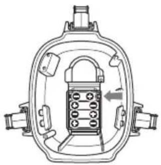
natural_image
Cross-sectional diagram of a mechanical device with internal components and no visible text or symbols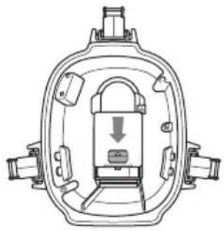
natural_image
Technical line drawing of a mechanical component with internal structure and mounting points (no text or symbols)② à la prise LANC
natural_image
Technical line drawing of a car engine compartment showing internal components (no text or symbols)natural_image
Technical line drawing of a mechanical component with no visible text or symbolsnatural_image
Technical line drawing of a mechanical device with attached wires and components (no text or symbols)natural_image
Line drawing of a mechanical device with no visible text or symbols5 Fixez la poignée.
Vissez fermement la vis.
natural_image
Diagram of a mechanical device with a rotating knob and handle (no text or symbols)natural_image
Technical line drawing of a mechanical component with internal parts, showing cross-sectional and exploded views (no text or symbols)natural_image
Technical line drawing of a mechanical component with hoses and connectors (no text or symbols)natural_image
Technical line drawing of a mechanical device with a suspended component (no text or symbols)natural_image
Technical line drawing of a mechanical device with no visible text or symbols5 Fixez la poignée.
Vissez fermement la vis.
natural_image
Diagram of a hand holding a mechanical device with a circular component and rotational arrow (no text or symbols)natural_image
Technical line drawing of a mechanical component with two views (top and side), no visible text or symbolsnatural_image
Technical line drawing of a mechanical component with no visible text or symbolsnatural_image
Technical line drawing of a mechanical device with internal components (no text or symbols)natural_image
Line drawing of a mechanical device with no visible text or symbolsnatural_image
Diagram of a mechanical device with a rotating wheel and handle mechanism (no text or symbols)natural_image
Line drawing of a device with a circular component and a separate cylindrical component, no text or symbols present.natural_image
Technical line drawing of a mechanical device with attached wires and components (no text or symbols)natural_image
Diagram of a device interior showing internal components and directional arrows (no text or symbols)natural_image
Technical line drawing of a mechanical device with no visible text or symbolsnatural_image
Technical line drawing of a mechanical device with two views: one showing internal components and the other showing external housing (no text or symbols)natural_image
Technical line drawing of a mechanical device with internal components and directional arrows indicating movement (no text or symbols)natural_image
Technical line drawing of a mechanical assembly with no visible text or symbols5 Débranchez de la prise AUDIO/VIDEO
natural_image
Technical line drawing of a mechanical assembly (no text or symbols visible)natural_image
Technical line drawing of a mechanical device with two views: top shows internal components, bottom shows external housing (no text or symbols)natural_image
Diagram of a hand inserting a device into a mechanical component, showing internal components and directional arrows (no text or symbols)natural_image
Technical line drawing of an internal mechanical assembly (no text or symbols)natural_image
Line drawing of a video camera with attached cables (no text or symbols)natural_image
Technical line drawing of a mechanical component with no visible text or symbolsFR
natural_image
Illustration showing two hands performing a medical procedure: one pinning a tube and the other holding a curved tube (no text or symbols present)natural_image
Technical line drawing of a rectangular mechanical component with mounting holes (no text or symbols)Mauvais
natural_image
Diagram of a mechanical component with a circular feature and a magnified inset (no text or symbols)Bon
Contrôle final
natural_image
Line drawing of a bag with a handle and belt, showing a scroll wheel and hanging cable (no text or symbols)natural_image
Technical line drawing of a mechanical component with attached cable (no text or symbols)2
natural_image
Isometric line drawing of a 3D mechanical part with two circular holes and a rectangular body (no text or symbols)3
natural_image
Line drawing of a device casing with internal components and mounting holes (no text or symbols)4
Gruesa
Fina

5

natural_image
Isometric line drawing of a mechanical housing component with mounting holes and internal slots (no text or symbols)6

natural_image
Technical line drawing of a mechanical component or housing (no text or symbols)7

natural_image
Technical line drawing of a mechanical device with no visible text or symbols8
9
10
1

12 13 14 15


16 17 18

natural_image
Line drawing of a coiled cable or wire with a connector (no text or symbols)19

natural_image
Line drawing of a portable electronic device with attached straps and ventilation slots (no text or symbols)Para DCR-PC109/PC109E/PC108/PC108E/PC107E/PC106E
natural_image
Technical line drawing of a device with internal components and labeled section A (no text or symbols present)Para DCR-TRV900/TRV900E/TRV890E/TRV9/TRV9E
natural_image
Technical line drawing of a video camera with attached electronic device (no text or symbols)natural_image
Technical line drawing of a video camera assembly with visible wiring and components (no text or labels)natural_image
Line drawing of a device with arrows indicating motion or assembly (no text or symbols)
natural_image
Line drawing of a hand holding a mechanical component with a circular arrow indicating rotation (no text or symbols)natural_image
Simple line drawing of a mechanical component with a knob and rotating arrow (no text or symbols)natural_image
Diagram of a mechanical component with a threaded rod and a cylindrical base, showing electrical connections (no text or symbols)natural_image
Diagram of a mechanical component with a threaded fastener and a curved arrow indicating rotation (no text or symbols)natural_image
Diagram showing a device being adjusted for a hand press, with no text or symbols present.natural_image
Technical line drawing of a mechanical device with internal components and an upward arrow indicating motion (no text or symbols)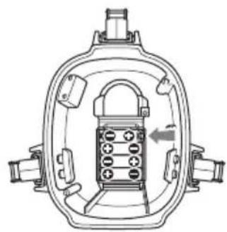
natural_image
Technical line drawing of a mechanical component with internal components and directional arrow (no text or symbols)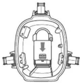
natural_image
Cross-sectional diagram of a mechanical device with internal components and a downward arrow indicating motion (no text or symbols)② a la toma LANC
natural_image
Technical line drawing of a car engine compartment showing internal components and wiring (no text or symbols)natural_image
Technical line drawing of a mechanical assembly with hoses and components (no text or symbols)natural_image
Technical line drawing of a mechanical device with attached wires and components (no text or symbols)natural_image
Technical line drawing of a mechanical device with no visible text or symbols5 Fije el asa.
natural_image
Diagram of a mechanical device with a rotating knob and handle (no text or symbols)natural_image
Technical line drawing of a mechanical component with internal parts and mounting holes (no text or symbols)natural_image
Technical line drawing of a mechanical component with no visible text or symbolsnatural_image
Technical line drawing of a mechanical assembly with no visible text or symbolsnatural_image
Line drawing of a mechanical device with no visible text or symbolsnatural_image
Diagram of a hand holding a mechanical component with a circular arrow indicating rotation (no text or symbols)natural_image
Technical line drawing of a mechanical component with internal parts, showing a close-up view of the internal structure (no text or symbols)natural_image
Technical line drawing of a mechanical component with no visible text or symbolsnatural_image
Technical line drawing of a mechanical device with internal components (no text or symbols)natural_image
Line drawing of a mechanical device with ports and a handle (no text or symbols)5 Fije el asa.
natural_image
Line drawing of a mechanical device with a circular arrow indicating rotation or motion (no text or symbols)natural_image
Line drawing of a device with a circular button and a separate cylindrical component, no text or symbols presentnatural_image
Technical line drawing of a mechanical device with attached wires and components (no text or symbols)natural_image
Technical line drawing of a mechanical device with internal components and directional arrows indicating movement (no text or symbols)natural_image
Technical line drawing of a mechanical device with no visible text or symbolsnatural_image
Technical line drawing of a mechanical device with two views: one showing internal components and the other showing external housing (no text or symbols)natural_image
Technical line drawing of a mechanical device with internal components and directional arrows indicating movement (no text or symbols)natural_image
Technical line drawing of a mechanical assembly with no visible text or symbolsnatural_image
Technical line drawing of a mechanical device with no visible text or symbolsnatural_image
Technical line drawing of a mechanical device with two views: front view and side view (no text or symbols)natural_image
Diagram of a hand holding a device with arrows indicating motion or force direction (no text or symbols present)natural_image
Technical line drawing of an internal mechanical assembly (no text or symbols)natural_image
Line drawing of a vintage video camera with attached cables (no text or symbols)natural_image
Technical line drawing of a mechanical component with no visible text or symbolsES
natural_image
Illustration showing a hand holding a small tube and another hand holding a curved tube, both without any text or symbols.natural_image
Technical line drawing of a mechanical component with no visible text or symbols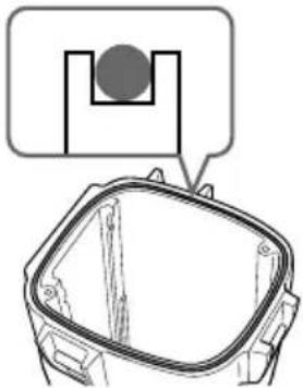
natural_image
Technical line drawing of a mechanical component with a highlighted inset showing a circular feature (no text or symbols)natural_image
Line drawing of a handbag with a ribbon and belt, showing a scroll wheel (no text or symbols)natural_image
Technical line drawing of a mechanical component with connectors and housing (no text or symbols)2
natural_image
Isometric line drawing of a 3D mechanical part with two circular holes and a rectangular body (no text or symbols)3
natural_image
Line drawing of a rectangular electronic device casing with internal components (no text or symbols)4
厚
薄
natural_image
Two identical 3D rectangular shapes with internal cutouts, no text or symbols present5
natural_image
Isometric line drawing of a mechanical housing or enclosure with internal components (no text or symbols)6

natural_image
Technical line drawing of a mechanical component (no text or symbols)7

natural_image
Technical line drawing of a mechanical device with no visible text or symbols8
9
10
1
12 13 14 15
natural_image
Simple line drawing of a rounded rectangular container with a rectangular lid (no text or symbols)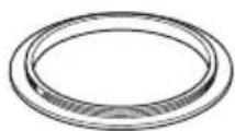
16 17 18
natural_image
Line drawing of a coiled cable or wire with a terminal connector (no text or symbols)19
natural_image
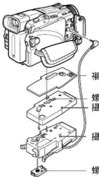
Line drawing of a portable electronic device with attached cable and connectors (no text or symbols)1攝影機安裝極鞋 B (1)
2 襯墊 C (1)
3攝影機安裝極鞋 D (1)
4攝影機安裝極鞋 D 用墊子 (2)
5攝影機安裝極鞋 E (1)
6攝影機安裝極鞋 F (1)
7攝影機安裝極鞋 G (1)
natural_image
Technical line drawing of a device with internal components and cable routing (no text or symbols)用於 DCR-TRV900/TRV900E/TRV890E/TRV9/TRV9E
攝影機安裝極鞋 B 的螺栓板的安裝位置
natural_image
Line drawing of a device with arrows indicating process flow (no text or symbols)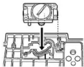
攝影機安裝極鞋 D 的螺栓板的安裝位置
螺栓板 攝影機安裝極鞋 D
攝影機安裝極鞋 B
螺栓板
natural_image
Mechanical assembly diagram showing a valve mechanism with no visible text or symbols攝影機安裝極鞋 E 的螺栓板的安裝位置
攝影機安裝極鞋 E
攝影機安裝極鞋 B
螺栓板
用於 DCR-TRV118E/ TRV116E/ TRV27/ TRV27E/ TRV25/ TRV25E/ TRV24E/ TRV18/ TRV18E/ TRV16/ TRV16E
攝影機安裝極鞋 B 的螺栓板的安裝位置
襯墊 C
螺栓板
攝影機安裝極鞋 E
攝影機安裝極鞋 B
螺栓板
natural_image
Diagram of a hand holding a mechanical component with a circular arrow indicating rotation (no text or symbols)2 把鋰電池插入握柄。
①用附帶的螺絲起子卸下螺絲。
natural_image
Simple line drawing of a mechanical component with a knob and rotating arrow (no text or symbols)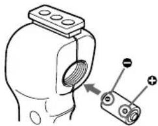
natural_image
Diagram of a mechanical component with a threaded part and a separate cylindrical component with positive charges (no text or symbols)
natural_image
Technical line drawing of a mechanical component with a threaded fitting and a curved arrow indicating rotation (no text or symbols)natural_image
Diagram showing a device being adjusted to form a device with a magnified view of the component (no text or symbols present)natural_image
Technical line drawing of a mechanical device with no visible text or symbols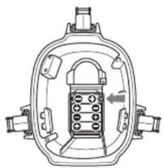
natural_image
Technical line drawing of a mechanical component with internal components and a directional arrow (no text or symbols)
natural_image
Technical line drawing of a mechanical component with internal structure and directional arrow (no text or symbols)請使用新的乾電池。
natural_image
Technical line drawing of a car engine compartment showing internal components and wiring (no text or symbols)3 把監視器導線連接到與攝影機連接的
A/V 轉換電纜上。
natural_image
Technical line drawing of a vehicle interior showing hoses and brackets (no text or symbols)natural_image
Technical line drawing of a mechanical device with attached wires and components (no text or symbols)natural_image
Technical line drawing of a mechanical device with no visible text or symbols5 安装握柄。
旋緊螺絲。
natural_image
Technical line drawing of a mechanical component with a circular arrow indicating rotation (no text or symbols)到這裡已完成使用準備。
natural_image
Technical line drawing of a mechanical component with internal parts, showing two views (top and side), no text or symbols present.natural_image
Technical line drawing of a mechanical component with no visible text or symbolsnatural_image
Technical line drawing of a mechanical device with a suspended component (no text or symbols)natural_image
Technical line drawing of a mechanical device with no visible text or symbols5 安装握柄。
旋緊螺絲。

natural_image
Diagram of a mechanical device with a circular arrow indicating rotation or cycle (no text or symbols)到這裡已完成使用準備。
natural_image
Technical line drawing of a mechanical component with two views (top and side), no visible text or symbolsnatural_image
Technical line drawing of a vehicle rear panel with hoses and components (no text or symbols)natural_image
Technical line drawing of a mechanical device with internal components (no text or symbols)natural_image
Line drawing of a mechanical device with no visible text or symbols5 安装握柄。
旋緊螺絲。

natural_image
Diagram of a mechanical device with a rotating knob and handle, no text or symbols present到這裡已完成使用準備。
natural_image
Line drawing of a device with a circular component and a separate cylindrical component, no text or symbols present.裝上廣角轉換鏡頭至牢固地裝緊。
使用附帶的物鏡遮光罩
natural_image
Technical line drawing of a mechanical device with attached wires and components (no text or symbols)4 自前殼中取出攝影機。
拿著攝影機安裝極鞋的捏手,取出攝影機。
natural_image
Technical line drawing of a mechanical device with internal components and directional arrows indicating movement (no text or symbols)natural_image
Technical line drawing of a mechanical device with internal components (no text or symbols)6 從攝影機上拆下安裝極鞋。
7 從液晶顯示監視器電池座內取出電池。
用於 DCR-PC109/PC109E/PC108/PC108E/PC107E/PC106E
1 卸下握柄。
natural_image
Technical line drawing of a mechanical device with two views: one showing internal components and the other showing external housing (no text or symbols)natural_image
Technical line drawing of a mechanical device with internal components and directional arrows indicating movement (no text or symbols)4 拆開遙控插頭和麥克風插頭。
natural_image
Technical line drawing of a mechanical assembly (no text or symbols visible)natural_image
Technical line drawing of a mechanical device with no visible text or symbolsnatural_image
Technical line drawing of a mechanical device with two views: top shows internal components, bottom shows external housing (no text or symbols)3 自前殼中取出攝影機。
natural_image
Technical line drawing of a mechanical device with arrows indicating motion or assembly (no text or symbols)4 拆開遙控插頭和麥克風插頭。
natural_image
Technical line drawing of a mechanical assembly (no text or symbols visible)natural_image
Line drawing of a vintage camera with attached cables (no text or symbols)6 用螺絲起子卸下攝影機安裝極鞋。
natural_image
Technical line drawing of a mechanical component with no visible text or symbols0 形環須知
0 形環是什麼?
natural_image
Simple diagram showing a black circle inside a square with an arrow pointing upward, no text or symbols present.natural_image
Illustration showing a hand holding a tube and a close-up of hands holding a curved cable or wire (no text or symbols present)natural_image
Technical line drawing of a mechanical housing or bracket (no text or symbols)不良例 優良例
natural_image
Diagram of a mechanical component with a circular inset showing a U-shaped feature, no text or symbols present.最後的檢查
natural_image
Line drawing of a handbag with straps and a bow, showing motion arrows (no text or symbols)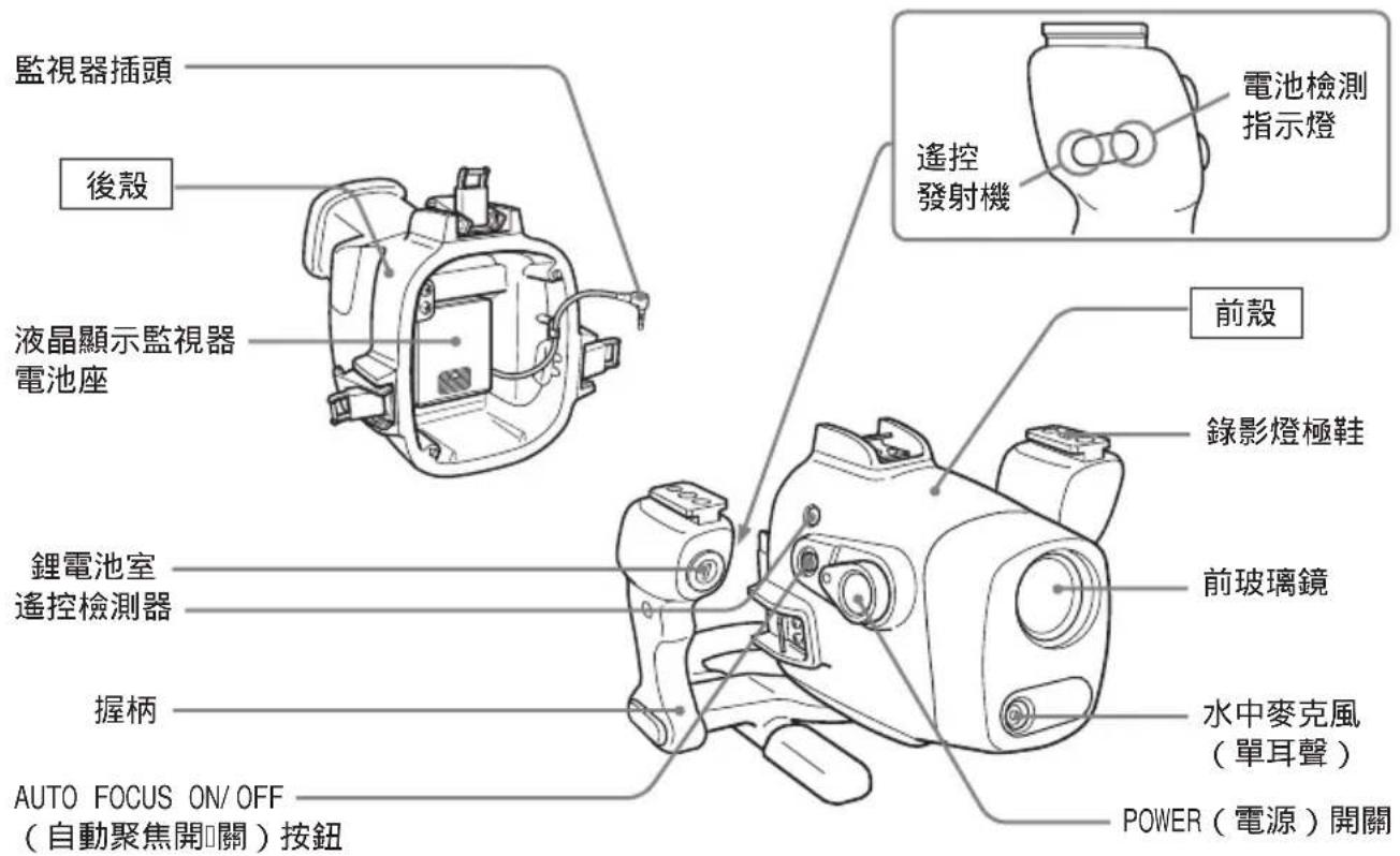
natural_image
Technical line drawing of a mechanical component with no visible text or symbols皮帶 攝影機安裝極鞋 G
natural_image
Technical line drawing of a mechanical component with attached cable (no text or symbols)2

natural_image
Isometric line drawing of a mechanical part with two circular holes and a rectangular body (no text or symbols)3

natural_image
Line drawing of a rectangular electronic device casing with internal components (no text or symbols)4
natural_image
Two simple 3D rectangular shapes with recessed cutouts, no text or symbols present5
natural_image
Isometric line drawing of a mechanical housing or enclosure with internal components (no text or symbols)6
natural_image
Technical line drawing of a mechanical component with no visible text or symbols7
natural_image
Technical line drawing of a mechanical device with no visible text or symbols8
9
10

1
12 13 14 15


16 17 18


natural_image
Line drawing of a coiled cable or wire with a terminal connector (no text or symbols)19

natural_image
Line drawing of a portable electronic device with attached cable (no text or symbols)1 B(1)
2 C(1)
3 D(1)
4 D D(2)
5 E(1)
6 F(1)
7 G(1)
8 B, D, E (2)
9□□□□(1)
□□□ □□□ □ B □ □□□□
10A / V □□ □□□( 1 )
11 CR2(1)
12O(1)
13 VCL - MK2 ( 1 )
14(1)
15 00 00 0(3)
☐: ∅ 37 mm(1)
☐: ∅ 30 mm(1)
☐: ∅ 25 mm(1)
16□□ □□( V F - MK2 ) ( 1 )
17(1)
18(3)
19 1000 10(1) 1000 10(1)
□□□□ □□□□
natural_image
Line drawing of a device with cable and plug, no text or symbols presentDCR-PC109/PC109E/PC108E/PC107E/PC1
G
① G □ □□□ □□ □□□□.
② A/V AUDIO/VIDEO
③ G □ □□ □□□ □□□ □
□□ □□□ □□□ □□□□□.
natural_image
Technical line drawing of a mechanical device with labeled component A (no text or symbols present)□□ □□□□ □□
DCR-TRV900/TRV900E/TRV9/TRV9E
natural_image
Cross-sectional diagram of a mechanical assembly with no visible text or symbols□□□ □□□ □ B □
□□ □□□□□ □□
□□ □□
1
DCR-TRV10/TRV10E/TRV8/
□□□ □□□ □ B, □□□□ C, □□
□□□□□ □□□□ □□□□.
① B C
②0 000 0000 000 000
□□□ □□□ □ B □
□□ □□□□□ □□
□□ □□
□□□□ C
□□□ □□□ □ B
□□ □□□□
DCR-TRV30/TRV30E/TRV20/TRV20E/TRV TRV15E/TRV11/TRV11E/TRV6/TRV6E□□□
□□□ □□□ □ B □ D, □□□ □□□ □ D □ □□ □ □□□ □□□□.
□□□□ □□□□ □□
D
□□□ □□□□.
| DCR- | □□□ □□□□□ □□□ □□□ □ B □ D | ||
| TRV30/TRV | 30E 2 | 1 □□ | |
| TRV20/TRV | 20E 2 | 1 □□ | |
| TRV17/TRV1 | 7E/25E | 3 | □□ |
| TRV15/TRV1 | |||
| TRV11/TRV1 | 1E/25E | 2 | □□ |
D D D D D D D D D
natural_image
Line drawing of a device with arrows indicating process flow (no text or symbols)D
□□ □□□□ □□
DCR-TRV50/TRV50E/TRV40/
B,E□□□□□□□□。
① 1 1 1 1 1 1 1 1 1 1 1 1 1 1 1 1 1 1 1 1 1 1 1 1 1 1 1 1 1
natural_image
Technical diagram of a mechanical assembly with no visible text or symbols□□□ □□□ □ E □ □□ □□□□□ □□ □□ □□
□□□ □□□ □ B
□ □ □ □□□□
□□□□ □□
□□□□ □□□□ □□ □□ □□□ □ □□□. □□ □□ □□ □□□ □□ □□ □□ □□ □□ □□ □□ □□ □□ □□ □□ □□ □□□.
6
natural_image
Diagram of a hand holding a mechanical component with a circular arrow indicating rotation (no text or symbols)2
①
natural_image
Simple line drawing of a mechanical component with a knob and curved arrow indicating rotation (no text or symbols)② 000 00 000( CR2, · 1) 0
□□ □□□ □□□ □□ □□□□
0000.

natural_image
Diagram of a mechanical component with a threaded part and a separate cylindrical component with labeled terminals (no text or symbols present)3
natural_image
Diagram of a mechanical component with a threaded fastener and a curved arrow indicating rotation (no text or symbols)3 3 □□ □□□ □□ □□ □□ □□□.
□□□ □□ □□ □□ □□ □□□□
natural_image
Diagram showing two views of a device with rotating buttons and a close-up view of the internal components (no text or symbols)□□ □□□□ □□
natural_image
Cross-sectional diagram of a mechanical device with internal components and an upward arrow (no text or symbols)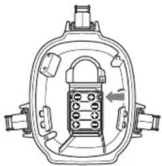
natural_image
Technical line drawing of a mechanical device with internal components and directional arrow (no text or symbols)
natural_image
Cross-sectional diagram of a mechanical device with internal components and a downward arrow indicating motion (no text or symbols)□ □□□□ □□□□□.
natural_image
Technical line drawing of a car engine compartment showing internal components (no text or symbols)natural_image
Technical line drawing of a vehicle rear view showing internal components like hoses and brackets (no text or labels)natural_image
Technical line drawing of a mechanical device with no visible text or symbols4
3
natural_image
Line drawing of a mechanical device with no visible text or symbols5
000 000 0000.
natural_image
Diagram of a hand holding a mechanical device with a circular arrow indicating rotation (no text or symbols)□□□□ □□□ □□□□□□□.
natural_image
Technical line drawing of a mechanical component with internal parts, showing cross-sectional and side views (no text or symbols)3 G.
natural_image
Technical line drawing of a mechanical component with no visible text or symbolsnatural_image
Technical line drawing of a mechanical assembly with no visible text or symbols
natural_image
Technical line drawing of a mechanical device with no visible text or symbols
natural_image
Diagram of a mechanical device with a rotating wheel and handle mechanism (no text or symbols)

1
□□□ □□□□ □□□□□ □□□□
□□□□□.
① MICRO MICRO MICRO MICRO MICRO MICRO MICRO MICRO MICRO MICRO MICRO MICRO MICRO MICRO MICRO MICRO MICRO MICRO MICRO MICRO MICRO MICRO MICRO MICRO MICRO MICRO MICRO MICRO MICRO MICRO MICRO MICRO MICRO MICRO MICRO MICRO MICRO MICRO MICRO MICRO MICRO MICRO MICRO MICRO MICRO MICRO MICRO MICRO MICRO MICRO MICRO MICRO MICRO MICRO MICRO MICRO MICRO MICRO MICRO MICRO MICRO MICRO MICRO MICRO MICRO MICRO MICRO MICRO MICRO MICRO MICRO MICRO MICRO MICRO MICRO MICRO MICRO MICRO MICRO MICRO MICRO MICRO MICRO MICRO MICRO MICRO MICRO MICRO MICRO MICRO MICRO MICRO MICRO MICRO MICRO MICRO MICRO MICRO MICRO MICROMICROMICROMICROMICROMICROMICROMICROMICROMICROMICROMICROMICROMICROMICROMICROMICROMICROMICROMICROMICROMICROMICROMICROMICROMICROMICROMICROMICROMICROMICROMICROMICROMICROMICROMICROMICROMICROMICROMICROMICROMICROMICROMICROMICROMICROMICROMICROMICROMICROMICROMICROCROMICROMICROMICROMICROMICROMICROMICROMICROMICROMICROMICROMICROMICROMICROMICROMICROMICROMICROMICROMICROMICROMICROMICROMICROMICROMICROMICROMICROMICROMICROMICROMICROMICROMICROMICROMICROMICROMICROMICROMICROMICROMICROMICROMICROMICROMICROMICROMICROMICRO Microcro Microcro Microcro Microcro Microcro Microcro Microcro Microcro Microcro Microcro Microcro Microcro Microcro Microcro Microcro Microcro Microcro Microcro Microcro Microcro Microcro Microcro Microcro Microcro Microcro Microcro Microcro Microcro Microcro Microcro Microcro Microcro Microcro Microcro Microcuro Microcuro Microcuro Microcuro Microcuro Microcuro Microcuro Microcuro Microcuro Microcuro Microcuro Microcuro Microcuro Microcuro Microcuro Microcuro Microcuro Microcuro Microcuro Microcuro Microcuro Microcuro Microcuro Microcuro Microcuro Microcuro Microcuro Microcuro Microcuro Microcuro Microcuro Microcuro Microcuro MicrocuroMicro micromicromicromicromicromicromicromicromicromicromicromicromicromicromicromicromicromicromicromicromicromicromicromicromicromicromicromicromicromicromicromicromicromicromicromicromicromicromicromicromicromicromicromicromicromicromicromicromicromicromicromicromicromicromicromicromicromicromicromicromicromicromicromicromicromicromicromicromicromicromicromicromicromicromicromicromicromicromicromicromicromicromicromicromicromicromicromicromicromicromicromicromicromicromicromicromicromicromicromicromicroMicro micro micro micro micro micro micro micro micro micro micro micro micro micro micro micro micro micro micro micro micro micro micro micro micro micro micro micro micro micro micro micro micro micro micro micro micro micro micro micro micro micro micro micro micro micro micro micro micro micro micro micro micro micro micro micro micro micro micro micro micro micro micro micro micro micro micro micro micro micro micro micro micro micro micro micro micro micro micro micro micro micro micro micro micro micro micro micro micro micro micro micro micro micro micro micro micro micro micro micro micro micromicro microscope
□□□□( □□□ □ □□) .
② LANC
□□□□□.
②LANC
□□□
2
□□ □□□□ □□□□.
natural_image
Technical line drawing of a mechanical component with internal parts, showing two views (top and side), no text or symbols present.3 B
□□□ □□□□□.

natural_image
Technical line drawing of a mechanical component with no visible text or symbols□□□ □□□□ □□ □□ □□□
□□□ □□□□□□. □□□ □□
□ □□□□ □□□□ □□ □□□
.

natural_image
Technical line drawing of a mechanical device with internal components (no text or symbols)□□ □□□□ □□

natural_image
Line drawing of a mechanical device with no visible text or symbols
natural_image
Diagram of a mechanical device with a rotating circular component, no text or symbols present
natural_image
Technical line drawing of a mechanical component with no visible text or symbols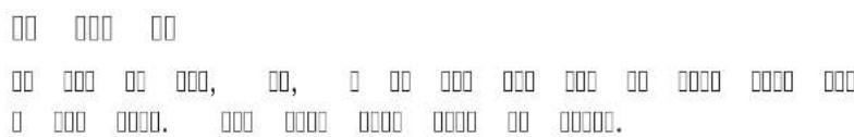
PHOTO "Memory Stick"
( "Memory Stick" )
□□□ □□□□. )
PHOTO
natural_image
Technical line drawing of a device with a circular component and a cylindrical lens, showing no text or symbols.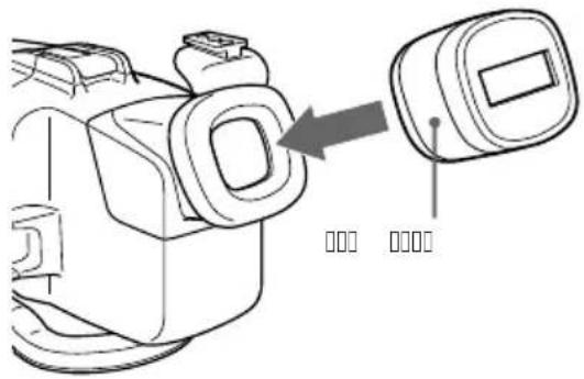
natural_image
Line drawing of a camera module with an arrow pointing to a button (no text or symbols)
natural_image
Technical line drawing of a device with a dial and a separate circular component (no text or symbols)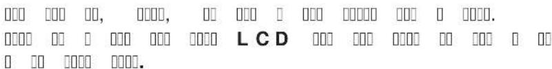
natural_image
Line drawing of a knot tied with strings, no text or symbols present
natural_image
Technical line drawing of a mechanical component with no visible text or symbols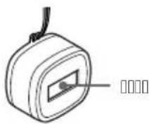
Sony HVL-ML20M(□□□) □□ □□
natural_image
Line drawing of a handheld electronic device with two lenses and a camera (no text or symbols)
Sony
□□ □□□
• 000 000 000 000 00 00 00 00 0000 00 00 30 \~ 60 0
000 00 000 00, 000 000 000 000 000 000 000.
- Sony
natural_image
Technical line drawing of a mechanical device with attached wires and connectors (no text or symbols)4
□□□ □□□ □□□ □□ □□□ □□ □□□. □□ □□ □ □□□ □□□ □□□ □□□ □ □ □□ □□□.
natural_image
Technical line drawing of a mechanical device with internal components and directional arrows indicating movement (no text or symbols)5 000 000, 0000 000, A / V 00 000 0 000.

natural_image
Technical line drawing of a mechanical device with no visible text or symbols6
7 LCD
DCR-PC109/PC109E/PC108/PC108E/PC
1 000 000.
23.
G
natural_image
Technical line drawing of a mechanical device with two views: one showing internal components and the other showing external housing (no text or symbols)3
natural_image
Technical line drawing of a mechanical device with internal components and directional arrows (no text or symbols)4.
natural_image
Technical line drawing of a mechanical assembly with no visible text or symbols5 G A/V
AUDIO/VIDEO
natural_image
Technical line drawing of a mechanical assembly (no text or symbols visible)6
□ □□□ □ G □ □□□ □□□ □□□ □□ □□□.
7 LCD

1 000 000.
natural_image
Technical line drawing of a mechanical device with two views: top shows internal components, bottom shows external housing (no text or symbols)3
natural_image
Diagram of a hand holding a mechanical device with arrows indicating motion or assembly (no text or symbols present)4 000 000 000 000 0 000.
natural_image
Technical line drawing of an internal mechanical assembly (no text or symbols)5 B A/V AUDIO/VIDEO
natural_image
Line drawing of a vintage digital camera with attached cables (no text or symbols)6
7 LCD □□□ □□□□□ □□□ □□□.
□□ □□ □□□ □□□
natural_image
Technical line drawing of a mechanical component with no visible text or symbols○ □□□ □□□□□?
natural_image
Technical line drawing of a mechanical component with no visible text or symbols○ □□ □□ □□
natural_image
Line drawing of a computer monitor with a stand and label (no text or symbols present)natural_image
Pure electrical circuit lines without any symbols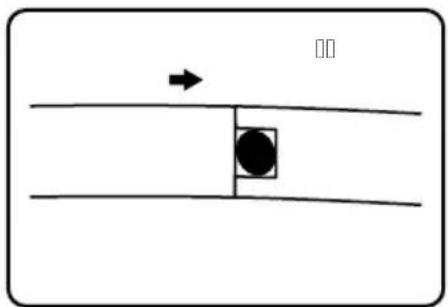
natural_image
Simple diagram with a black circle inside a square and an arrow pointing upward, no text or symbols present.O □ □□□ □□□□ O □ □□□ □□□□ □ □ □ □□□ □ □ □□□.
natural_image
Simple line drawing of a hand holding a pipette with liquid (no text or symbols)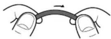
natural_image
Illustration of two hands holding a curved object with an arrow indicating rotation (no text or symbols)natural_image
Technical line drawing of a mechanical housing or bracket (no text or symbols)
natural_image
Technical line drawing of a mechanical component with a highlighted section (no text or symbols)□□□□ □□ □ □□□ □
□□□ □□
O( No. 3-977-362-01)
☐☐☐( ☐☐ No. 3 - 0 7 1 - 3 7 0 - 0 1)
natural_image
Line drawing of a handbag with ribbon and belt, showing a scroll wheel (no text or symbols)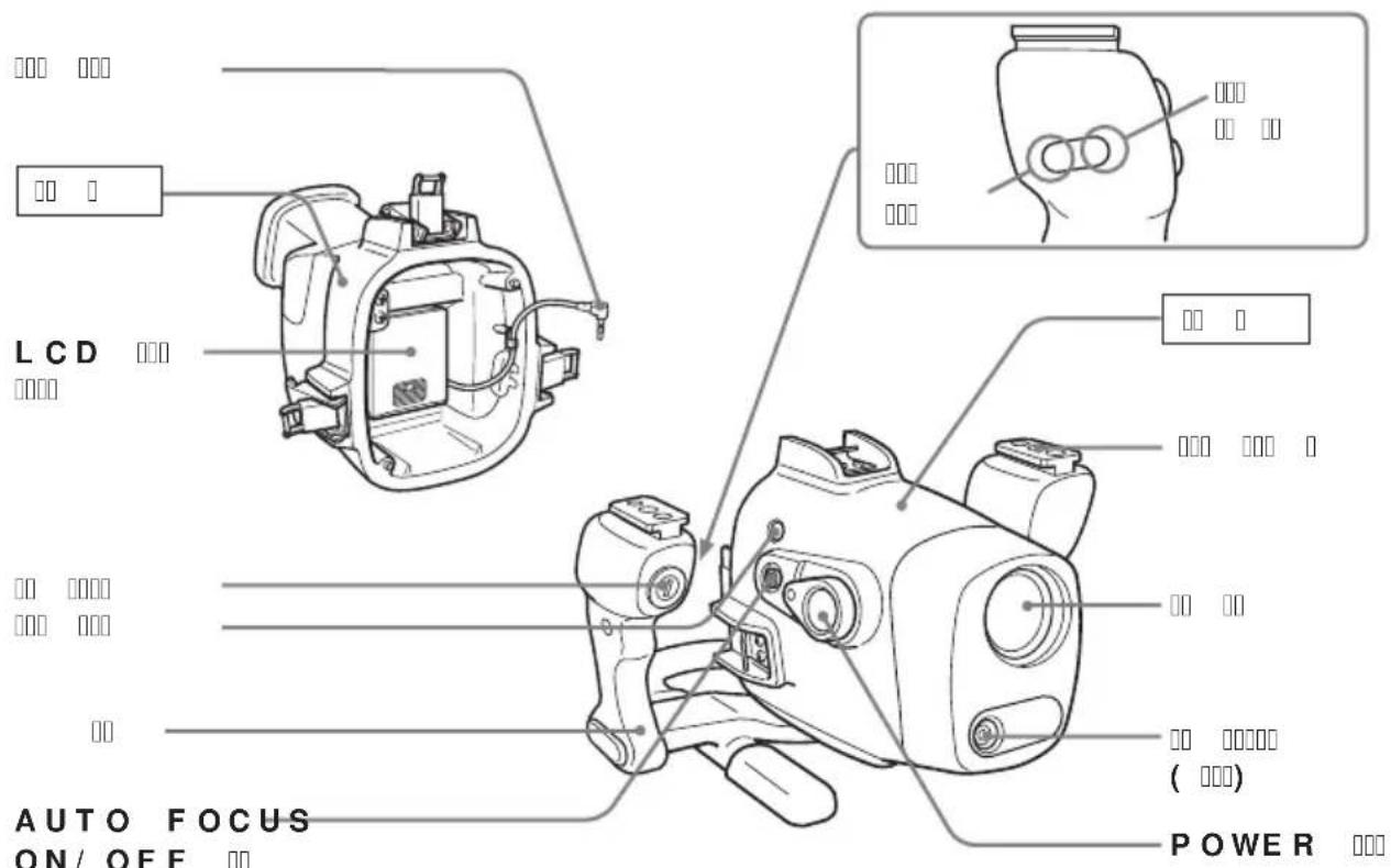
Printed on 100% recycled paper using VOC (Volatile Organic Compound)-free vegetable oil based ink.