UNAPSTN - Other camera accessories SONY - Free user manual and instructions
Find the device manual for free UNAPSTN SONY in PDF.
| Product Type | USB-PSTN modem adapter for USB-compatible camcorder |
| Brand | Sony |
| Model | UNAPSTN |
| Dimensions (L × H × D) | 86 × 17.1 × 65 mm |
| Weight | Approximately 54 g |
| Power supply | Via USB bus, 5 V DC voltage |
| Power consumption | 250 mA max |
| Connection interface | USB Mini-A and RJ-11 (telephone line) |
| Telephone line type | Analog |
| USB transmission speed | 12 Mbps max |
| Error correction protocols | MNP Class 4/10, ITU-T V.42 |
| Compression protocols | MNP Class 5, ITU-T V.42bis |
| Dialing type | Multi-frequency (Tone) or pulse (10/20 pps) |
| Transmission sensitivity | -10 to -15 dBm |
| Operating temperature | 0 °C to +40 °C |
| Storage temperature | -20 °C to +60 °C |
| Included accessories | Telephone cable (1), operating instructions |
| Main functions | Internet connection via telephone line, compatible with Sony camcorders with USB network card |
| Maintenance and cleaning | Wipe with a soft, dry cloth; use a mild detergent if necessary |
| Safety precautions | Do not expose to rain or moisture; avoid high temperatures and dusty environments |
| Certifications | CE, Industry Canada (NMB-003) |
| Destination countries | Germany, Australia, Austria, Belgium, Canada, Denmark, United States, Finland, France, Greece, Hong Kong, Ireland, Japan, Luxembourg, New Zealand, Norway, Netherlands, Portugal, Singapore, Sweden, Switzerland, United Kingdom, Italy, Spain, Taiwan |
Frequently Asked Questions - UNAPSTN SONY
User questions about UNAPSTN SONY
0 question about this device. Answer the ones you know or ask your own.
Ask a new question about this device
Download the instructions for your Other camera accessories in PDF format for free! Find your manual UNAPSTN - SONY and take your electronic device back in hand. On this page are published all the documents necessary for the use of your device. UNAPSTN by SONY.
USER MANUAL UNAPSTN SONY
USB - PSTN Modem Adaptor
Operating Instructions
Mode d'emploi
Owner's Record
The model and serial numbers are located on the bottom of the unit.
Record the serial number in the space provided below.
Refer to these numbers whenever you call upon your Sony dealer regarding this product.
Model No. UNA-PSTN Serial No.
UNA-PSTN
English
Before operating the unit, please read this instructions thoroughly, and retain it for future reference.
WARNING
To prevent fire or shock hazard, do not expose the unit to rain or moisture.
Countries and areas
This product is intended to be used in the following countries or areas. Australia, Austria, Belgium, Canada, Denmark, Finland, France, Germany, Greece, Hong Kong, Ireland, Japan, Luxembourg, Netherlands, New Zealand, Norway, Portugal, Singapore, Sweden, Switzerland, UK, USA, Italy, Spain, Taiwan
Regulatory Information
For the Customers in the USA
CAUTION
You are cautioned that any changes or modifications not expressly approved in this manual could void your authority to operate this equipment.
THIS DEVICE COMPLIES WITH PART 15 OF THE FCC RULES.
OPERATION IS SUBJECT TO THE FOLLOWING TWO CONDITIONS:
(1) THIS DEVICE MAY NOT CAUSE HARMFUL INTERFERENCE, AND
(2) THIS DEVICE MUST ACCEPT ANY INTERFERENCE RECEIVED, INCLUDING INTERFERENCE THAT MAY CAUSE UNDESIRED OPERATION.
NOTE:
This equipment has been tested and found to comply with the limits for a Class B digital device, pursuant to Part 15 of the FCC Rules. These limits are designed to provide reasonable protection against harmful interference in a residential installation.
This equipment generates, uses, and can radiate radio frequency energy and, if not installed and used in accordance with the instructions, may cause harmful interference to radio communications.
2-GB
However, there is no guarantee that interference will not occur in a particular installation. If this equipment does cause harmful interference to radio or television reception, which can be determined by turning the equipment off and on, the user is encouraged to try to correct the interference by one or more of the following measures:
— Reorient or relocate the receiving antenna.
— Increase the separation between the equipment and receiver.
— Connect the equipment into an outlet on a circuit different from that to which the receiver is connected.
— Consult the dealer or an experienced radio/TV technician for help.
FCC Part 68
This equipment complies with Part 68 of the FCC rules and the requirements adopted by the ACTA. On the bottom of this equipment is a label that contains, among other information, a product identifier in the format US : 1KRM500BUNAPSTN. If requested, this number must be provided to the telephone company.
A telephone plug and jack used to connect this equipment to the premises wiring and telephone network must comply with the applicable FCC Part 68 rules and requirements adopted by the ACTA.
This modem uses the USOC RJ-11 telephone jack.
A plug and jack used to connect this equipment to the premises wiring and telephone network must comply with the applicable FCC Part 68 rules and requirements adopted by the ACTA. A compliant telephone cord and modular plug is provided with this product. It is designed to be connected to a compatible modular jack that is also compliant. See installation instructions for details.
The REN is used to determine the quantity of devices that may be connected to a telephone line. Excessive RENs on a telephone line may result in the devices not ringing in response to an incoming call. In most, but not all areas, the sum of the RENs should not exceed five (5.0). To be certain of the number of devices that may be connected to a line, as determined by the total RENs, contact the telephone company. For products approved after July 23, 2001, the REN for this product is part of the product identifier that has the format US: 1KRM500BUNAPSTN. The digits represented by 00 are the REN without a decimal point (e.g., 03 is a REN of 0.3). For earlier products, the REN separately shown on the label.
If this equipment causes harm to the telephone network, the telephone company will notify you in advance that temporary discontinuance of service may be required. But if advance notice is not practical, the telephone company will notify the customer as soon as possible. Also, you will be advised of your right to file a complaint with the FCC if you believe it is necessary.
The telephone company may make changes in its facilities, equipment, operations or procedures that could affect the operations of the equipment. If this happens, the telephone company will provide advance notice in order for you to make the necessary modifications in order to maintain uninterrupted service.
If trouble is experienced with this equipment, please contact 1-800-222-SONY (7669), or write to the Sony Customer Information Service Center, at 12451 Gateway Blvd., Fort. Myers, Fl 33913 for repair and (or) warranty information.
If the equipment is causing harm to the telephone network, the telephone company may request you remove the equipment until the problem is resolved.
Repair of this equipment should be made only by a Sony Service Center or Sony authorized agent. For the Sony Service Center nearest you, call 1-800-222-SONY (7669).
This equipment can not be used on public coin service. Connection to Party Line Service is subject to state tariffs. (Contact the state public utility service commission, public service commission, or corporation commission for information.)
If your home has specially wired alarm equipment connected to the telephone line, ensure the installation of this equipment does not disable your alarm equipment.
If you have questions about what will disable alarm equipment, consult your telephone company or a qualified installer.
For the Customers in CANADA
This Class B digital apparatus complies with Canadian ICES-003.
INDUSTRY CANADA NOTICE
This product meets the applicable Industry Canada technical specifications.
The Ringer Equivalence Number (REN) is an indication of the maximum number of devices allowed to be connected to a telephone interface. The termination on an interface may consist of any combination of devices subject only to the requirement that the sum of the RENs of all the devices does not exceed five.
For the Customers in Europe
CE
Hereby, Sony Corporation, declares that this USB-PSTN modem adaptor is in compliance with the essential requirements and other relevant provisions of the Directive 1999/5/EC.
For details, please access the following URL:
http://www.compliance.sony.de/
This equipment is in compliance with the requirements of the directive 1999/5/EC (R&TTE), to be connected with all European analogue PSTN. However, due to differences between the individual PSTNs provided in the different countries, the compliance does not, on itself, give an unconditional assurance of successful operation on every PSTN network termination point. In the event of problems, you should contact your equipment supplier in the first instance.
If the plug of exclusive modem cable is not match with the telephone terminal jack, attach an optional plug adaptor. The plug type of the exclusive modem cable is the RJ-11 type.
Table of contents
Precautions on Use 8
Precautions on Handling 9
Maintenance 9
Parts identification .... 10
Before Use 10
Setting up the unit 11
Preparation 14
Connecting to a telephone line with a PSTN modem adaptor...... 14
Accessing the Internet 15
Disconnecting the USB-PSTN modem adaptor from your camcorder..... 16
Troubleshooting....17
Specifications 18
Introduction
- USB connection enables data transmission between an Internet and a USB network adaptor compatible camcorder via a modem.
- The USB-PSTN modem adaptor is a bus powered device and therefore requires no power supply.
Trademark
The system names and product names recorded in this instruction manual are in general registered trademarks or trademarks of their respective developing manufacturers. This instruction manual does not specify ^TM and ^ signs.
Precautions on Use
Where not to place this device
Regardless of whether the USB-PSTN modem adaptor is in use or in storage, do not place it in any of the following locations. Doing so may lead to breakdown.
- Locations of extremely high temperature
The temperature gets extremely high inside a car with the windows closed in summer or in strong sunshine, and leaving the USB-PSTN modem adaptor inside may cause it to be deformed or break down. - Locations with excessive humidity, dust, soot or steam
Using the USB-PSTN modem adaptor in such an environment may lead to fire or electric shock.
- Locations where young children can touch it
There is a risk of injury, electric shock and breakdown.
- Only use a designated connecting cable
Using a connecting cable not specified in this manual may lead to fire or breakdown.
- Avoid incorrect connection
- Do not allow any small pieces of metal inside the connector.
A short between pins may lead to fire or breakdown.
- Insert the connector completely straight. Inserting it at an angle can cause a short between pins, which may lead to fire or breakdown.
- Unplug the telephone cable before moving the USB-PSTN modem adaptor
Moving it with the telephone cable still connected may damage the cable or lead to fire, electric shock, or injury if the USB-PSTN modem adaptor drops or falls over. Also be careful not to drop the USB-PSTN modem adaptor.
• In direct sunlight or near a heater
There is a risk of deformation or breakdown.
- Locations of excessive vibration
- Locations with strong electromagnetism
- Locations with excessive sand
In locations such as the seashore and other sandy areas or where dust clouds occur, protect the USB-PSTN modem adaptor from sand and dust. There is a risk of breakdown.
Precautions on Handling
- Using the USB-PSTN modem adaptor reduces the amount of time you can use your camcorder, because they share the camcorder's battery.
- When not using the USB-PSTN modem adaptor, disconnect it from your camcorder to prevent your camcorder's battery from going flat.
- Do not lift your camcorder by the USB-PSTN modem adaptor or its cable.
- Do not pull out the connector by pulling the cable.
- Do not bend or apply excessive force to the cable.
Maintenance
Wipe the USB-PSTN modem adaptor with a soft dry cloth. If the USB-PSTN modem adaptor is very dirty, wipe it using a cloth with a little neutral solvent added, and then wipe it dry again.
Do not use thinners, benzine, alcohol, etc., as they will damage the surface of the USB-PSTN modem adaptor.
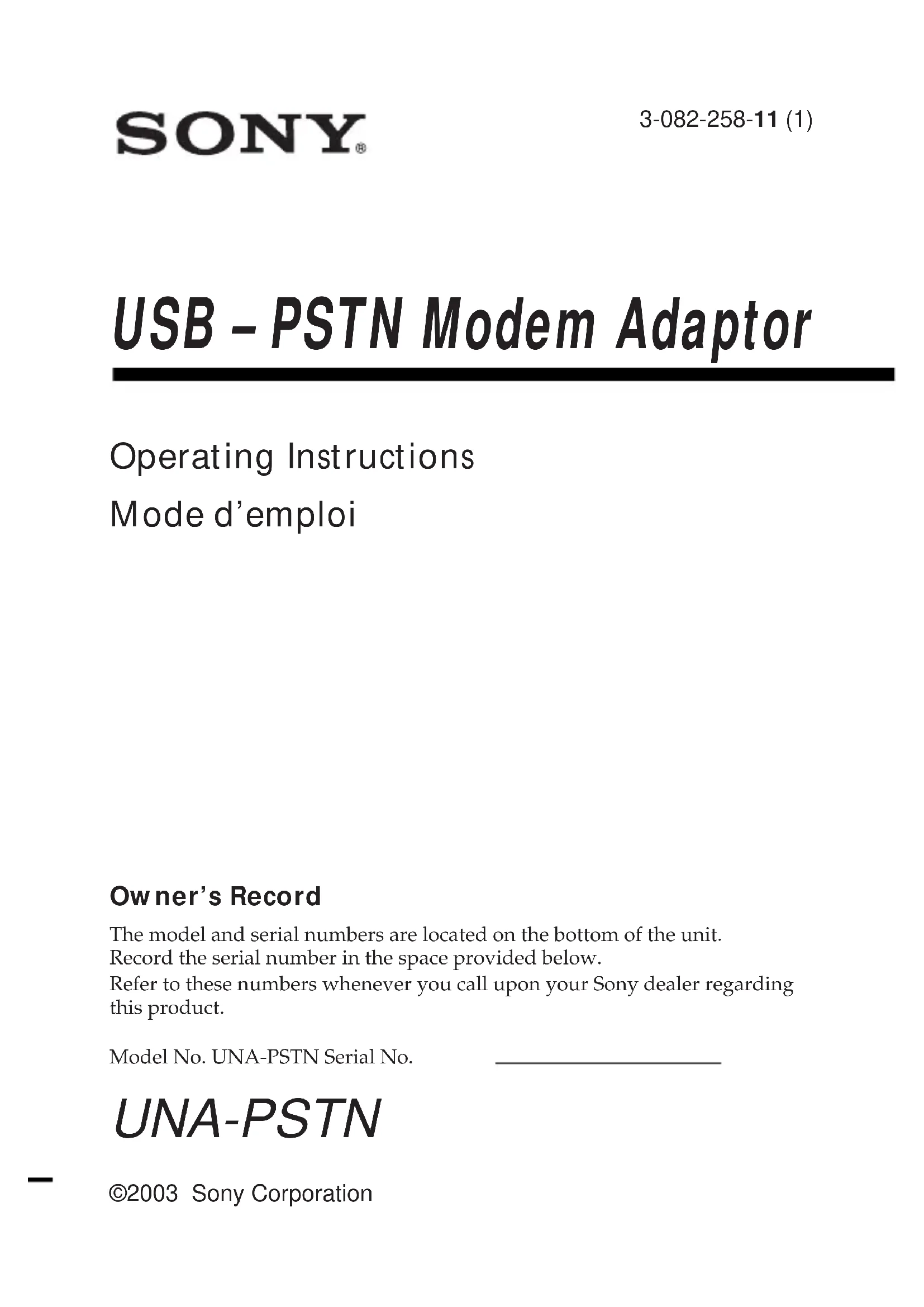
Parts identification
When connecting the USB-PSTN modem adaptor, do so correctly by checking the shape of the connectors.
1 POWER lamp (green)
2 ON LINE lamp (orange)
3 DATA lamp (orange)
4 USB connector
5 RJ-11 connector
6 Switch cover
7 AREA CODE switches
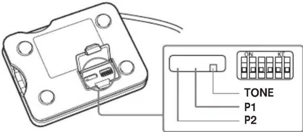
8 TONE/P1 (PULSE10)/P2 (PULSE20) selector
USB connector : For connection to USB compatible camcorders RJ-11 connector : For connection to a telephone cable
Before Use
- This USB-PSTN modem adaptor is exclusively for use with a USB network adaptor compatible camcorder. Before use, refer to your "Network Function/Application Operating Instructions".
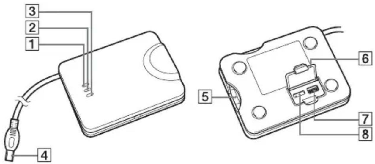
Setting up the unit
You must make certain settings before you can connect the unit to your telephone line. Choose the proper settings for your telephone signaling type. You also have to set the AREA CODE switches according to your area.
(1) Be sure that this unit is not connected to the USB-PSTN modem adaptor compatible camcorders or a RJ-11 cable (telephone cable).
(2) Open the switch cover.
(3) Select the telephone signaling type with the TONE/P1 (PULSE10)/P2 (PULSE20) selector.
TONE: When your phone line has tone signaling.
PULSE10: When your phone line has pulse signaling.
PULSE20: Normally, this is not used. For details, see "To check the dial speed of a pulse dialing phone" on page 12.
Tips
•How can I tell if my phone has tone signaling?
You can hear the touch pad sound from your phone when you press the number button.
• How can I tell if my phone has pulse signaling?
You can hear clicking sounds from your phone when you press the number button.
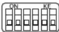
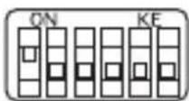
(4) Set up the AREA CODE switches according to your area. For details, see "The setup of the AREA CODE switches" on page 13.
Setting up the unit (continued)
(5) Close the cover.
The setting is completed.
Notes
- If the TONE/P1 (PULSE10)/P2 (PULSE20) selector is not set to the appropriate position, you cannot communicate with the camcorder.
- If you cannot check the dial speed of your pulse dialing phone, set the TONE/P1 (PULSE10)/P2 (PULSE20) selector to P1 (PULSE10).
- In some countries and areas, TONE/P1 (PULSE10)/P2 (PULSE20) setting is not required.
In such a country or area, the USB-PSTN modem adaptor communicates by the telecom protocol in that country or area, regardless of the TONE/P1 (PULSE10)/P2 (PULSE20) setting.
To check the dial speed of a pulse dialing phone
You can change the dialing speeds of some pulse dial phones. To check the dial speed, switch the dial speed selector on the phone and check the clicking sound. The slower one is the normal setting. When you select the fast dial speed, set the TONE/P1 (PULSE10)/P2 (PULSE20) selector to P2 (PULSE20).
The setup of the AREA CODE switches
The default AREA CODE setting is "Japan".
Set the AREA CODE switches to the appropriate positions using a sharp-pointed object following the information given in the table below. You cannot use the unit in areas other than the areas indicated on the table.
Notes
- "1" for the parameter in the table indicates that setting the switch to the ON side.
- The relationship between the 6-digit numbers in the table and the switch positions is as illustrated below.
(e. g., when you set to Japan) (e. g., when you set to the USA)
The setup list for the AREA CODE switch
| Country or area | Parameter | Country or area | Parameter | Country or area | Parameter |
| Japan 000000 Greece 110100 Sw | Sweden 010110 | ||||
| United States 100000 Ireland 101100 Switzerland 110110 | |||||
| Australia 010000 Italy 011100 Taiwan 001110 | |||||
| Austria 110000 Netherlands 010010 United Kingdom 101110 | |||||
| Belgium 001000 New Zealand 110010 Canada 100000 | |||||
| Denmark 111000 | Norway 001010 | Hong Kong 100000 | |||
| Finland 000100 Portugal | 011010 Luxembourg | 001000 | |||
| France 100100 Singapore 111010 | |||||
| Germany 010100 Spain 100110 | |||||
Preparation
To connect to the Internet, first you must connect the USB-PSTN modem adaptor to a USB network adaptor-compatible camcorder.
Connecting to a telephone line with a PSTN modem adaptor
Connect to the Internet via a telephone line using a USB-PSTN modem adaptor.
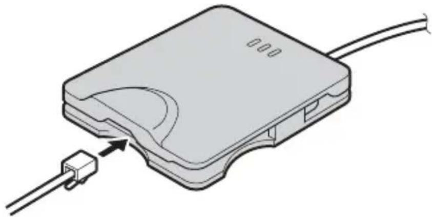
natural_image
Line drawing of a digital camera connected to a USB flash drive (no text or symbols)1 Connect the supplied telephone cable to this unit and the modular jack of the telephone.
natural_image
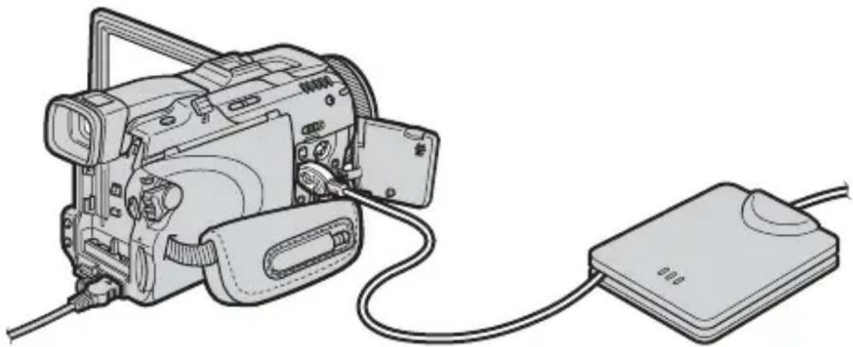
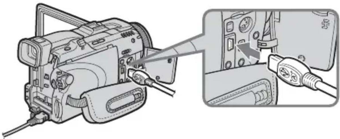
Diagram of a device with a connector and cable, showing an internal component and a terminal block (no text or symbols present)2 Attach the USB-PSTN modem adaptor's USB connector to (USB) jack of your camcorder.
natural_image
Diagram of a camera with cable inserted, showing internal components and cable connector (no text or symbols)Note
The position of (USB) jack varies from model to model.
For details, refer to your USB network adaptor compatible camcorder's instruction manual.
3 Set your USB network adaptor compatible camcorder's power switch to "MEMORY/NETWORK" to display the Network Menu.
Your camcorder is now ready for communication.
Note
Connect the USB-PSTN modem adaptor directly to your USB network adaptor compatible camcorder. The camcorder is not compatible with a USB hub.
Accessing the Internet
For details of how to log on, refer to your USB network adaptor compatible camcorder's "Network Function/Application Operating Instructions".
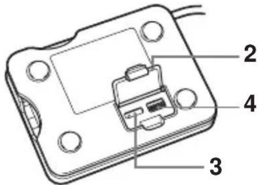
Disconnecting the USB-PSTN modem adaptor from your camcorder
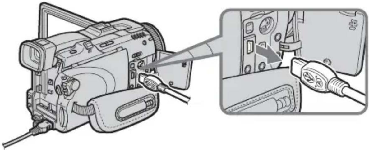
1 Remove the USB-PSTN modem adaptor's USB connector from (USB) jack of your camcorder.
natural_image
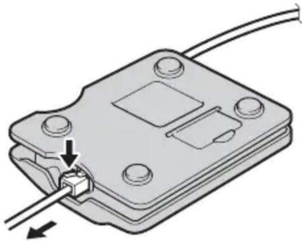
Diagram of a camera module being inserted into a device, showing cable and connector (no text or symbols present)2 Remove the telephone cable from the USB-PSTN modem adaptor.
natural_image
Diagram of a mechanical component with a cable and connector, showing a pin inserted into a housing (no text or symbols present)Troubleshooting
Before sending the USB-PSTN modem adaptor for repairs, read this manual and the support information on our website http://www.sony.net/. If the USB-PSTN modem adaptor still does not work properly, consult your Sony dealer or local authorized Sony service facility.
| Symptom Cause/Measures | |
| A USB error occursex) Connection ErrorConnect USB Device | ·Check that the USB-PSTN modem adaptor is correctly connected to the USB terminal of your USB network adaptor compatible camcorder. If it is not, reconnect it. |
| A PPP error occursex) Connection ErrorCheck phone line | ·The AREA CODE switch is incorrectly set.→Set it correctly. For details, see “Setting up the unit” (page 11).·The line is busy. (Another device is using the phone line.)→Try again when the other device has stopped communicating.·Cannot connect to the other telephone line.→Wait a while before trying again.·Cannot communicate well sometimes depending on the status of the telephone line.→Turn off the camcorder, turn it back on, then try to communicate again.·The USB-PSTN modem adaptor cannot be used with a home or business telephone line. (Never connect it to a home or business telephone line. Doing so can lead to malfunction, overheating and fire.) |
Specifications
Modem part
Applicable line Analog telephone line
Interface for the telephone circuit 2 line ceremony interface
NCU AA
Dial type Pulse dialing (10/20 pps)
Tone dialing
NCU command AT command
Communication format Dual
Sending communication rate 300/1200/2400/4800/7200/9600/
12000/14400/16800/19200/21600/
24000/26400/28800/31200/33600 bps
Receiving communication rate 300/1200/2400/4800/7200/9600/
12000/14400/16800/19200/21600/
24000/26400/28800/31200/33600/
34000/34667/36000/37333/38000/
38667/40000/41333/42000/42667/
44000/45333/46000/46667/48000/
49333/50000/50667/52000/53333/
54000/54667/56000 bps
Modulation mode standard ITU-T V.21/V.22/V.22bis/V.32/
V.32bis/V.34/V.90, BELL 212A/
103, K56flex ^TM
Sender sensitivity -10 to -15 dBm
Error correction MNP Class 4/10, ITU-T V.42
Data compression MNP Class 5, ITU-T V.42bis
USB interface part
Telecommunication standard USB compatible
Interface connector Mini-A plug
Transmission rate max. 12 Mbps
Power supply Bus-powered
Operating voltage DC 5 V (supplied by USB interface)
Power consumption max. 250 mA
General
Outer dimensions
Weight approx. 54 g (1.9 oz)
Operating temperature 0^ C \~ +40°C
Storage temperature -20^ +60^
Accessories
Telephone cable (1)
Operating Instructions
Design and specifications are subject to change without notice.
Français
natural_image
Line drawing of a digital camera connected to a computer via cable (no text or symbols)natural_image
Diagram of a device with a connector and cable, showing an internal component connected to a terminal block (no text or symbols present)Préparation (suite)
natural_image
Diagram of a camera module being inserted into a device, showing cable and connector (no text or symbols present)Remarque
natural_image
Diagram of a camera with cable and connector, showing internal components connected to a device (no text or symbols present)natural_image
Diagram of a mechanical component with a cable and connector, showing a pin inserted into a housing (no text or symbols present)Dépannage
Commande NCU Commande AT
Format de communication Double
Sending communication rate 300/1200/2400/4800/7200/9600/
12000/14400/16800/19200/21600/
24000/26400/28800/31200/33600 bps
Receiving communication rate 300/1200/2400/4800/7200/9600/
12000/14400/16800/19200/21600/
24000/26400/28800/31200/33600/
34000/34667/36000/37333/38000/
38667/40000/41333/42000/42667/
44000/45333/46000/46667/48000/
49333/50000/50667/52000/53333/
54000/54667/56000 bps
Norme de modulation ITU-T V.21/V.22/V.22bis/V.32/
V.32bis/V.34/V.90, BELL 212A/
103, K56flex ^TM
Printed on 100% recycled paper using VOC (Volatile Organic Compound)-free vegetable oil based ink.