
HWW 550050 M - Pump METABO - Free user manual and instructions
Find the device manual for free HWW 550050 M METABO in PDF.
| Product type | Surface pump with pressure tank (booster pump) |
| Brand and model | Metabo HWW 550050 M |
| Dimensions (L x W x H) | 535 x 275 x 590 mm |
| Weight (empty) | 18.8 kg |
| Weight (with water) | 40.3 kg |
| Power supply | 230 V ~ 50 Hz, 1500 W, 6.7 A |
| Protection | IP 44, class I |
| Maximum flow rate | 5500 l/h |
| Maximum delivery head | 55 m |
| Maximum delivery pressure | 5.5 bar |
| Maximum suction height | 9 m |
| Maximum water temperature | 50 °C |
| Ambient temperature | 5 to 40 °C |
| Tank volume (pressure vessel) | 24 L |
| Maximum tank pressure | 5.0 bar |
| Tank pre-charge pressure | 1.5 bar |
| Cut-in pressure | ~2.5 bar |
| Cut-out pressure | ~4.0 bar |
| Suction connection | 1" internal thread |
| Discharge connection | 1" internal thread |
| Main applications | Watering, irrigation, rainwater pumping, pool drainage, domestic supply |
| Maintenance and cleaning | Clean suction filter regularly; drain before frost; check pre-charge pressure |
| Safety | Thermal motor protection; do not use for drinking water; avoid dry running; use a 30 mA residual current device |
| Spare parts and repairability | Available accessories: connection set, filter, filter cartridge, check valve, hose. Repairs by a specialist |
Frequently Asked Questions - HWW 550050 M METABO
User questions about HWW 550050 M METABO
0 question about this device. Answer the ones you know or ask your own.
Ask a new question about this device
Download the instructions for your Pump in PDF format for free! Find your manual HWW 550050 M - METABO and take your electronic device back in hand. On this page are published all the documents necessary for the use of your device. HWW 550050 M by METABO.
USER MANUAL HWW 550050 M METABO
EG-KONFORMITÄTSERKLÄRUNGVEC-DECLARATION OF CONFORMITY
We herewith declare in our sole responsibility that this product complies with the following standards in accordance with the regulations of the undermentioned Directives issuing test office *** measured/ guaranteed noise sound power level***
NL
HWW 5500/20 M/HWW 5500/50 M
- EN 60335-1, EN 60335-2-41. EN 50081-1, EN 61000-3-2, EN 61000-3-3, EN 55014, EN ISO 3744
2006/95, 2004/108/EG, 2000/14/EG Annex VI, P<15KW
Director Innovation, Research and Development
Dokumentationsbevollmachtigter/ responsible person for documentation/ Chargé de la documentation
Metabowerke GmbH
Metabo-Allee 1
D-72622 Nurtingen
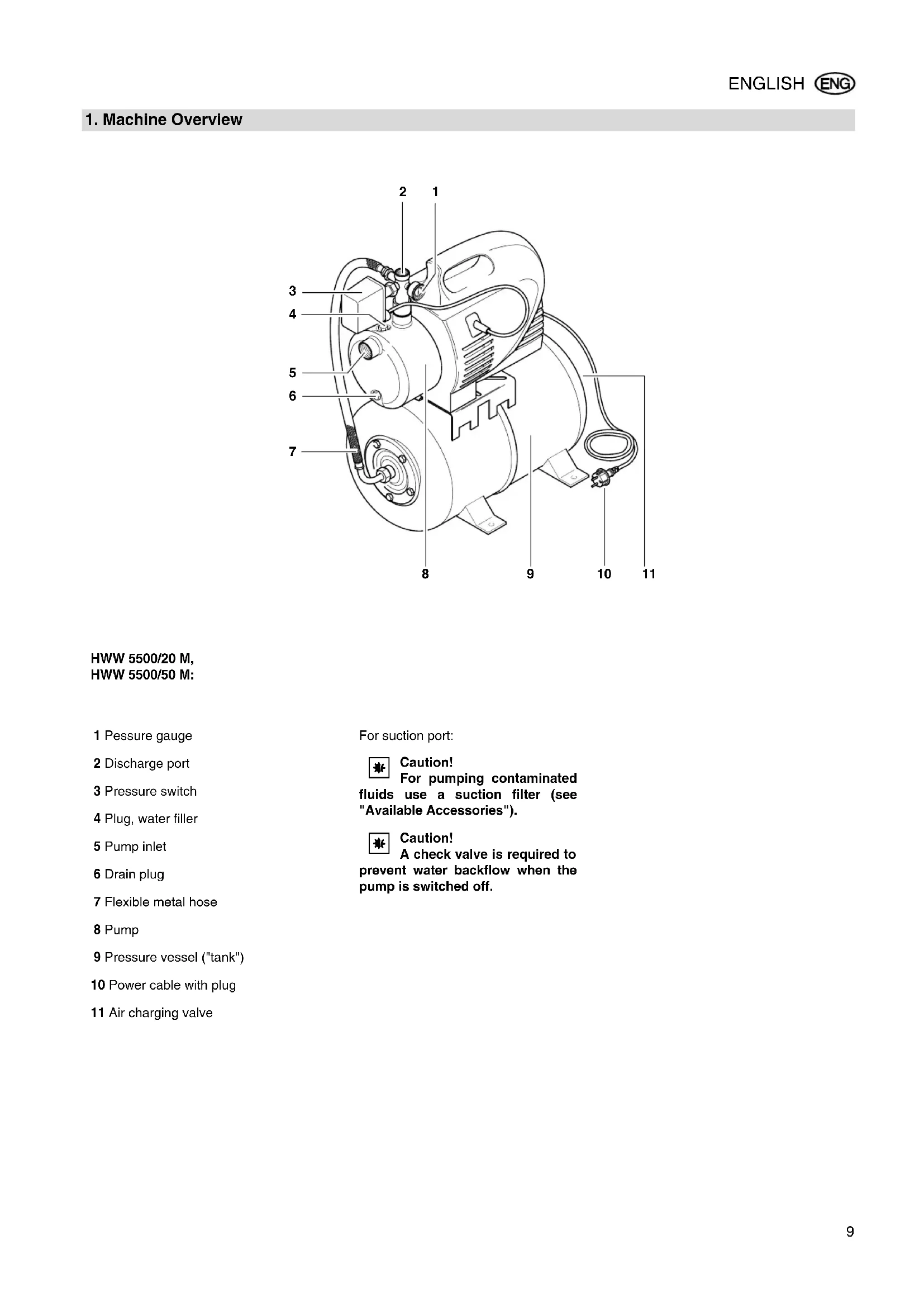
HWW 5500/20 M, HWW 5500/50 M:
1 Pessure gauge
2 Discharge port
3 Pressure switch
4 Plug, water filler
5 Pump inlet
6 Drain plug
7 Flexible metal hose
8 Pump
9 Pressure vessel ("tank")
10 Power cable with plug
11 Air charging valve
For suction port:

Caution!
For pumping contaminated
fluids use a suction filter (see "Available Accessories").

Caution!
A check valve is required to
prevent water backflow when the pump is switched off.
Table of Contents
- Machine Overview.. 9
- Please Read First! 10
-
Range of Application and Pumping Media....10
-
Safety 10
4.1 Specified conditions of use 10
4.2 General safety instructions.. 10
- Prior to Operation 11
5.1 Installation 11
5.2 Suction line connection 11
5.3 Discharge hose connection.....11
5.4 Connection to a pipe system.....11
5.5 Mains connection 11
5.6 Filling the pump and priming 11
- Operation 11
6.1 Commissioning 11
6.2 Pump characteristic curve..12
- Care and Maintenance..12
7.1 Periodic maintenance.. 12
7.2 Danger of freezing.. 12
7.3 Equipment dismounting and storing 12
- Trouble Shooting 12
8.1 Fault finding. 12
8.2 Pressure switch adjustment 12
8.3 Increasing the air charge. 13 - Repairs 13
- Environmental Protection .13
- Available Accessories 13/66
- Technical Specifications 14
2. Please Read First!
- Read these instructions before use. Pay special attention to the safety instructions.
- Disregard of the operating instructions invalidates the manufacturer's warranty; the manufacturer is not liable for any damages resulting from such disregard.
If you notice shipping damage while unpacking, notify your supplier immediately. Do not operate the machine! - Dispose of the packing in an environmentally friendly manner. Take to a proper collecting point.
- Keep these instructions for reference on any issues you may be uncertain about.
- If you lend or sell this machine be sure to have the instructions go with it.
3. Range of Application and Pumping Media
This equipment is intended for pumping clear water in domestic applications, such as
- irrigation,
well, rain and service water pumping,
draining of pools, garden ponds and water tanks.
The max. permissible temperature of the pumped medium is 35^
4. Safety
4.1 Specified conditions of use
This equipment must not be used to supply drinking water or for pumping foodstuff.
Explosive, inflammable, aggressive fluids or substances detrimental to health and salt water must not be pumped.
This equipment is not suitable for commercial or industrial use.
Alteration of the equipment or use of parts not approved by the equipment manufacturer is not permitted.
Any inexpert use the equipment is not as specified; it can cause unforeseen damage!
4.2 General safety instructions
Children, juveniles and persons not familiar with the instructions are not permitted to operate the pump.
When used in swimming pools and garden ponds and their range of protection, the regulations according to DIN VDE 0100-702, -738 are to be observed.
When used as domestic water supply any applicable local regulations pertaining to water supply and waste water disposal, plus DIN 1988 (where applicable) are to be observed.
The following residual risks do principally exist when operating pumps and pressure vessels and can not be fully eliminated - even by employing safety devices.
Hazard by ambient conditions!
Do not expose to rain. Do not operate in damp or wet environment.
Do not direct water jet directly against the equipment or other electrical parts! Risk of fatal electric shock!
Do not use the pump in hazardous locations or near inflammable liquids and gases!

Danger: Hot water!
If the shut-off pressure of the pressure switch cannot be reached due to poor pressure conditions or a defective pressure switch the water can heat up within the pump as a result of internal circulation.
Through this the pump and the connection lines can become damaged or leaky, allowing hot water to escape. Danger of scalding!
- Do not operate the pump against a closed pressure line for longer than 5 minutes.
- Unplug the pump and allow to cool. A specialist must check the system to make sure it is in perfect working order before it can be used again.

Danger! Risk of electric shock!
Always unplug before servicing.
Do not touch the plug with wet hands! To unplug always pull on the plug, not the power cable.
Do not buckle, squeeze, drag or drive over power cable and extension cables; protect from sharp edges.

Danger by pump failings!
Before each use check the equipment, especially the power cable, plug and electrical parts for possible damage. Risk of fatal electric shock!
A damaged pump must be workmanlike repaired before it can be used again.
Do not attempt to repair the equipment yourself! Only trained specialists are permitted to service or repair pumps or pressure vessels.

Caution!
To avoid water damage, e.g. flooded rooms, caused by pump malfunctions or defects:
provide for suitable safety measures such as the following:
- alarm or
collection tank with monitoring.
The manufacturer is not liable for any damage caused by:
improper use of the pump;
- overloading of the pump through continuous operation;
- failure to operate and store the pump in a frost-free environment;
- unauthorised modification of the pump (repairs to electrical equipment may only be carried out by qualified electricians!);
- use of spare parts which have not been tested and approved by the manufacturer; or
- use of unsuitable installation materials (fittings, connection lines etc.).
Suitable installation materials:
- pressure-resistant (min. 10 bar)
heat-resistant (min. 100^)
5. Prior to Operation
The equipment is easily assembled and connected.
If in doubt, contact your specialist supplier or qualified electrician.
5.1 Installation
- The equipment must be placed on a plane and level surface, suitable of bearing the weight of the equipment fully filled with water.
- To prevent vibrations, the equipment should not be fastened with screws but placed onto an elastic base.
- The installation location should be well vented and protected from atmospheric exposure.
- When operated at garden ponds and pools the equipment must be set up safe against flooding and protected from falling into the water. Any additional legal requirements are to be observed.
5.2 Suction line connection

Note:
Possibly further accessories may be required for connection (see "Available Accessories").

Caution!
The suction line needs to be installed in such manner that it does not exert mechanical force or distortion to the pump.

Caution!
When pumping contaminated fluids install a suction strainer to protect the pump from sand and dirt.

Caution!
A check valve is required to prevent water backflow when the pump is switched off.
- All screw fittings need to be sealed with thread sealing tape; leakage places cause the priming of air and reduce or prevent the priming of water.
- The suction line should have at least 1'' (25 mm) inner diameter; it must be non-buckling and vacuum-proof.
- Keep suction line as short as practical, since with increasing length the pump capacity is reduced.
-
The suction line should raise towards the pump to prevent air locks.
-
A sufficient water supply must be ensured, the foot valve at the end of the suction line must be submerged in water at all times.
5.3 Discharge hose connection

Note:
Possibly further accessories may be required for connection (see "Available Accessories").

Caution!
The discharge (or pressure) line needs to be installed in such manner that it does not exert mechanical force or distortion to the pump.
- All screw fittings should be sealed with thread sealing tape to prevent leakage.
- All parts of the pressure line must be resistant to internal pressure.
- All parts of the pressure line must be installed in a workmanlike manner.

Danger!
Improper installation and use of parts not resistant to internal pressure can cause the pressure line to break during operation. Risk of personal injury by liquid spurting from the line under high pressure!
5.4 Connection to a pipe system
A permanent installation (e.g. for indoor domestic water supply) is also possible.
- To reduce vibrations and noise, the equipment should be connected to the piping with elastic hose pipes.
5.5 Mains connection

- Danger! Risk of electric shock!
-
Do not operate the equipment at environment and only under following conditions:
-
Connect only to an earthed outlet that is properly installed, earthed and tested.
- Mains voltage and fuse protection must correspond to those stated in the "Technical Specifications".
- When operated at pools, garden ponds and similar locations, the equipment must be protected by a residual current operated device (RCD, 30 mA) (DIN VDE 0100 -702, -738 or equivalent applicable local regulations). We recommend the use of RCD's as a general precaution for personal protection.
- When operated outdoors the electrical connections must be
splash-proof; they must not be placed in water.
- Use only extension cables of sufficient lead cross section (see "Technical Specifications"). Unroll cable reels fully.
5.6 Filling the pump and priming

Caution!
After installation, loss of water or priming of air the pump needs to be filled with water. Starting the pump without water causes damage!

Note:
The suction line does not need to be filled, the pump is self-priming. However, depending on length and diameter of the suction line it may take some time until pressure has built up.
- Remove the water filler plug, complete with gasket.
- Slowly pour in clear water, until the pump is filled.
- To reduce the time needed for priming you can also fill the suction line.
- Replace the water filler plug, complete with gasket.
- Open pressure line (open tap or spray nozzle) for any air to escape during priming.
- Start equipment (see "Operation").
- Close pressure line when only water runs out.
6. Operation
Pump and suction line must be connected and filled (see "Prior to Operation").

Caution!
Pump must not run dry. Ensure there is always sufficient pumping medium (water) available.
- If the motor does not start, no pressure is built up or similar effects are evident, switch the equipment OFF and try to remove the fault (see "Trouble Shooting").
If the pump should be blocked by a foreign object or the motor overheat, the motor protection will switch the motor off.
6.1 Commissioning

Note:
The pressure switch
- starts the pump when the water pressure in the tank falls below the cut-in pressure by drawing off water;
- stops the pump when the cut-out pressure is reached.

Note:
In the tank is a factory-
pressurized rubber bag ("air charge"); this enables the drawing-off of small amounts of water without starting the pump.
- Plug power cable in.
- Open pressure line (open tap or spray nozzle).
- Check to see the water comes out!
6.2 Pump characteristic curve
The pump characteristic curve shows which pump capacity is possible in dependence on the delivery head.
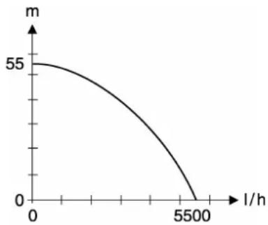
Pump characteristic curve at 0.5m suction head and 1" suction hose - for model:
HWW 5500/20 M, .../50 M
7. Care and Maintenance

Danger!
Prior to all servicing:
Unplug.
- Ensure that pressure is relieved from equipment and connected accessories.
Repair and maintenance work other than described here must only be carried out by qualified specialists.
7.1 Periodic maintenance
- Check equipment and accessories, especially electrical parts and parts under pressure for possible damage; have repaired, if necessary.
- Check suction and pressure lines for leakages.
If the pump capacity lessens clean suction strainer and filter cartridge (if installed), replace if necessary. - Check air charge of tank, increase if necessary (see "Increasing the air charge").
7.2 Danger of freezing

Caution!
Frost damages the pump and
accessories, as both always contain water!
- When there is danger of freezing, dismount equipment and accessories and store at a freeze-proof location (see below).
7.3 Equipment dismounting and storing
- Unplug.
- Open pressure line (open tap or spray nozzle) and drain water completely.
- Drain pump and tank completely. To do so,
remove the drain plug from the pump (except HWW 3300/20 K),
- loosen the union nut of the flexible metal hose at the tank.
- Disconnect suction and pressure lines from the equipment.
- Store equipment in a frost-free space (at least 5^ ).
8. Trouble Shooting

Danger!
Prior to all servicing:
Unplug.
- Ensure that pressure is relieved from equipment and connected accessories.
8.1 Fault finding
Pump does not run:
No mains voltage.
- Check cables, plug, outlet and mains fuse.
- Mains voltage too low.
-
Use only extension cables with sufficient lead cross section (see "Technical Specifications").
-
Motor overheated, motor protection relay tripped.
After cooling off the pump will switch ON again.
- Ensure sufficient ventilation, keep vent slots clear.
- Observe max. temperature of the pumped medium.
- Motor hums but does not start.
With the motor switched OFF, put screwdriver or similar through the fan cover's vent slots and turn the fan.
-
Pump blocked or out of order.
-
Disassemble pump and clean.
Clean diffusor, replace if necessary.
Clean impeller, replace if necessary.
Pump does not prime correctly or runs very noisily:
-
Lack of water.
-
Ensure there is a sufficient water supply.
-
Suction line leaky.
-
Seal suction line, tighten screw fittings.
-
Suction head too high.
-
Observe max. suction head.
Install check valve, fill suction line with water. -
Suction strainer (accessory) blocked.
Clean, replace if necessary.
- Check valve (accessory) blocked.
Clean, replace if necessary.
Water leaks between motor and pump, Ducone seal worn.
Replace Ducone seal.
- Pump blocked or out of order.
see above.
Pressure too low or pump running continuously:
- Suction line leaky or too much suction head.
see above.
- Pump blocked or out of order.
see above.
Pressure switch misadjusted.
-
Check cut-in and cut-out pressure, readjust if necessary.
-
Pump starts after only a minimal amount of water (approx. 0.5 l) has been drawn off.
Air charge in tank too low; increase.
Water drips form air charging valve.
Rubber bag in tank leaky; replace.
8.2 Pressure switch adjustment
If - during time - the factory-set cut-in and cut-out pressure changes considerably, it can be readjusted to the original setting (see "Technical Specifications").

Danger!
Risk of electric shock when touching the terminal inside the pressure switch. Only qualified service technicians are permitted to open and adjust the pressure switch.
- Remove the pressure switch cover.
- Open pressure line (open tap or spray nozzle) and drain water completely.
When the pumps starts, note cut-in pressure indicated by the pressure gauge.
- Close pressure line.
When the pumps stops, note cut-out pressure indicated by the pressure gauge.

Caution!
The factory-set cut-out pressure must not be exceeded.
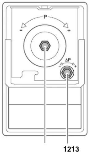
-
To change the cut-out pressure, turn nut (12)
-
clockwise to increase the cut-out pressure;
-
counter-clockwise to decrease the cut-out pressure.
-
To change the cut-in pressure, turn nut (13)
-
clockwise to increase the cut-in pressure;
counter-clockwise to decrease the cut-in pressure. -
If necessary, repeat steps 2. to 5. until the desired values are set.
- Put the pressure switch cover back on.
8.3 Increasing the air charge
If - during time - the pump starts after a minimal amount of water (approx. 0.5 l) is drawn off, the tank's air charge must be increased.

Note:
The air charge pressure can not be seen from the pressure gauge.
- Unplug.
- Open pressure line (open tap or spray nozzle) and drain water completely.
- Remove plastic cover from front of tank to have access to the air charging valve.
- Put air pump or air hose with tire chuck and pressure gauge on the air charging valve.
- Pump up to the rated air charge pressure (see "Technical Specifications").
- Reconnect equipment and check for proper functioning.
9. Repairs
A
Danger!
Repairs to electric tools must only be carried out by a qualified electrician!
Electric tools in need of repair can be sent to an authorised service center in your country. See spare parts list for address.
Please attach a description of the fault to the electric tool.
For shipping:
- Drain pump and tank completely (see "Equipment dismounting and storing").
- Uninstall pressure switch and pressure gauge (to prevent shipping damage).
- Ship equipment in original packing, if possible.
10. Environmental Protection
The packaging of the pump can be 100% recycled.
Worn out power tools and accessories contain considerable amounts of valuable raw and plastic materials, which can be recycled.
These instructions are printed on chlorine-free bleached paper.
11. Available Accessories
For this equipment the following accessories are available at specialist dealers.
Note: Illustra
Illustrations and stock numbers can be found at the end of these instructions.
A Pump Installation Package, complete with double nipple, check valve, pipe nipple 150~mm (2 pcs.), filter long, washable filter cartridge, spiral hose assembly 1m , elbow, hose bib with ball valve, thread sealing tape.
B Dry-running Stop Switch, with 10m cable, keeps the pump from running dry when pumping from tank, pool, etc.
C Spiral Hose 1"
1) 1 m assembly, with quick release screw fitting at both ends;
2) 4 m, complete with quick release screw fitting and strainer with foot valve;
3) 7 m, complete with quick release screw fitting and strainer with foot valve.
D Filter, 1" connection, long, complete with washable plastic filter cartridge.
E Disposable Filter Cartridge, long, for mechanical preliminary filtering of sand.
F Washable Filter cartridge, long, for mechanical preliminary filtering of sand, reusable.
G Activated Carbon Filter Cartridge, long, for use with chlorous water, removes odours or discolouring.
H Filter Cartridge Poly, long, filled with Polyphosphate, for calciferous water supplied to water heaters.
I Pipe Nipple 150 mm, 1^ male at both ends, galvanized, to connect pump and filter.
J Double Nipple, 1" male at boths ends.
K Check Valve 1" female, prevents water backflow and pump running dry.
L Thread Sealing Tape, 12 m roll.
12. Technical Specifications
| HWW 5500/20 M | HWW 5500/50 M | ||
| Mains voltage V 230 ~ 1 | |||
| Frequency | Hz | ||
| Rated output W 1500 | |||
| Rated current A 6.7 | |||
| Fuse protection min. (time-lag or L-type circuit breaker) A 10 | |||
| Running capacitor μF 20 | |||
| Rated speed min | -1 | 2800 | |
| Pump capacity max. l/h 5500 | |||
| Delivery head max. | m | 55 | |
| Delivery pressure max. | bar | 5.5 | |
| Max. suction head | m | 9 | |
| Temperature of the primed medium max. | °C | 50 | |
| Ambient temperature | °C | 5 ... 40 | |
| Protection class | IP 44 | ||
| Degree of protection | I | ||
| Insulation class | F | ||
| Materials | |||
| Pump casing | Stainless steel | ||
| Pump shaft | Stainless steel | ||
| Impeller | Noryl - 5x | ||
| Connections (female) | |||
| Pump inlet | 1" | ||
| Discharge port | 1" | ||
| Pressure switch | |||
| Cut-in pressure approx. | bar | 2.5 | |
| Cut-out pressure approx. | bar | 4.0 | |
| Tank | |||
| Tank capacity | I | 24 | 50 |
| Max. tank pressure | bar | 5.0 | 5.0 |
| Air charge pressure | bar | 1.5 | 1.5 |
| Dimensions (without connections) | |||
| Length | mm | 535 | 675 |
| Width | mm | 275 | 395 |
| Height | mm | 590 | 700 |
| Weights | |||
| Dry weight | kg | 18.8 | 24.9 |
| Weight filled with water | kg | 40.3 | 67 |
| Noise emission values (at max. pressure) | |||
| Sound power level LwAm | dB (A) | 75 | |
| Sound pressure level LwAd | dB (A) | 78 | |
| Max. length of extension cable | |||
| at 3 x 1.0 mm² lead cross-section | m | 30 | |
| at 3 x 1.5 mm² lead cross-section | m | 50 | |
50
HWW 5500/20 M, HWW 5500/50 M:
A HWW 5500/20 M, .../50 M
B HWW 4000/20 N,.../20 N Plus
C HWW 3300/20 K, HWW 3300/20
HWW 5500/20 M, HWW 5500/50 M:
Pomp verstopt of defect.
- Demonteer de pomp en reinig ze.
Diffusor reinigen,evt. verrangen. - Loopwiel reinigen, EVT. verwangen.
HWW 5500/20 M, HWW 5500/50 M:
HWW 5500/20 M, .../50 M
7. Mantenimiento

Peliciro!
HWW 5500/20 M, HWW 5500/50 M:
1 Manometer
2 Tilslutting at tryk
3 Trykknapafbryder
4 Vandpafyldningsskrue
5 Indsugningstilslutning
6 Vandafapningssskrue
7 Metalslange
8Pumper
9 Trykholder (Kedel")
10 Strömkabel med stik
11 Luftventil til forpafyldningstryk
HWW 5500/20 M, HWW 5500/50 M:
HWW 5500/20 M, ../50 M
Kataoyoos Pepieoxeewv
- SuovonTikn Tapouoiaaon Tns OoKEuN
- PpTeI va to 8iaaoteI.....48
- Πεδio xρησα κα μεσα μεταφοράς 48
4.AoPaaEia 48
4.1 PpOeT6eVn xpHON 48
4.2Evikεεπημαvαεις ασφαλείας 48 - Piv Tnv evapn Tns Aetoupyia
5.1 ToToeTnO
5.2 Suovdeo n oawna avappoqno...49
5.3 UvOeOToU OAnVa TnEONS.....49
5.4 SuVdEaon eE diktuo diavouns...49
5.5 SuVdoan oTo diKTuO TApoxnC peuato
5.6 PAnpwn avTiaac kai avappoqon.. 50 - Aetoupyia 50
6.1 Θεαη της σαικεύης σε
λειουργία………50
6.2 Xapakntpiotikn kaTtUa n avTAnon - Suvtnpnoan kai povtfia....50
7.1 Iepiodkn ouvtnpon.. 50
7.2 KivouoTayetou 50
7.3 Anouuapmooyntouakeun kai anoekuotey..51 - PpOβλnματα καI βλαβες 51
8.1 Avacntnna 51
8.2 Puroi on diakoknn Tieos 51
8.3 AuEnon nieons npoTAnpwoans...52 - Eπιοκεύη .52
- Pooataia tou TepiBaaovto52
- Diαεσιμα Προσετα Eαρτηματα………52//66
- TeyviKa XapaktniptiKa...53
2. PpEeV a to biaaTaTe!
HWW 5500/20 M HWW 5500/50 M:
HWW 5500/20 M, .../50 M
HWW 5500/20 M, HWW 5500/50 M:
HWW 5500/20 M, ../50 M
7. Huolto ja hoito

Vaara!
| 1.5% 2.5% 3.5% 4.5% 5% 6% 7% 8% 9% 10% 11% 12% 13% 14% 15% 16% 17% 18% 19% 20% 21% 22% 23% 24% 25% 26% 27% 28% 29% 30% 31% 32% 33% 34% 35% 36% 37% 38% 39% 40% 41% 42% 43% 44% 45% 46% 47% 48% 49% 50% 51% 52% 53% 54% 55% 56% 57% 58% 59% 60% 61% 62% 63% 64% 65% 66% 67% 68% 69% 70% 71% 72% 73% 74% 75% 76% 77% 78% 79% 80% 81% 82% 83% 84% 85% 86% 87% 88% 89% 90% 91% 92% 93% 94% 95% 96% 97% 98% 99% 100% 101% 102% 103% 104% 105% 106% 107% 108% 109% 110% 111% 112% 113% 114% 115% 116% 117% 118% 119% 120% 121% 122% 123% 124% 125% 126% 127% 128% 129% 130% 131% 132% 133% 134% 135% 136% 137% 138% 139% 140% 141% 142% 143% 144% 145% 146% 147% 148% 149% 150% 151% 152% 153% 154% 155% 156% 157% 158% 159% 160% 161% 162% 163% 164% 165% 166% 167% 168% 169% 170% 171% 172% 173% 174% 175% 176% 177% 178% 179% 180% 181% 182% 183% 184% 185% 186% 187% 188% 189% 190% 191% 192% 193% 194% 195% 196% 197% 198% 199% 200% 201% 202% 203% 204% 205% 206% 207% 208% 209% 210% 211% 212% 213% 214% 215% 216% 217% 218% 219% 220% 221% 222% 223% 224% 225% 226% 227% 228% 229% 230% 231% 232% 233% 234% 235% 236% 237% 238% 239% 240% 241% 242% 243% 244% 245% 246% 247% 248% 249% 250% 251% 252% 253% 254% 255% 256% 257% 258% 259% 260% 261% 262% 263% 264% 265% 266% 267% 268% 269% 270% 271% 272% 273% 274% 275% 276% 277% 278% 279% 280% 281% 282% 283% 284% 285% 286% 287% 288% 289% 290% 291% 292% 293% 294% 295% 296% 297% 298% 299% 300% 301% 302% 303% 304% 305% 306% 307% 308% 309% 310% 311% 312% 313% 314% 315% 316% 317% 318% 319% 320% 321% 322% 323% 324% 325% 326% 327% 328% 329% 330% 331% 332% 333% 334% 335% 336% 337% 338% 339% 340% 341% 342% 343% 344% 345% 346% 347% 348% 349% 350% 351% 352% 353% 354% 355% 356% 357% 358% 359% 360% 361% 362% 363% 364% 365% 366% 367% 368% 369% 370% 371% 372% 373% 374% 375% 376% 377% 378% 379% 380% 381% 382% 383% 384% 385% 386% 387% 388% 389% 390% 391% 392% 393% 394% 395% 396% 397% 398% 399% 400% 401% 402% 403% 404% 405% 406% 407% 408% 409% 410% 411% 412% 413% 414% 415% 416% 417% 418% 419% 420% 421% 422% 423% 424% 425% 426% 427% 428% 429% 430% 431% 432% 433% 434% 435% 436% 437% 438% 439% 440% 441% 442% 443% 444% 445% 446% 447% 448% 449% 450% 451% 452% 453% 454% 455% 456% 457% 458% 459% 460% 461% 462% 463% 464% 465% 466% 467% 468% 469% 470% 471% 472% 473% 474% 475% 476% 477% 478% 479% 480% 481% 482% 483% 484% 485% 486% 487% 488% 489% 490% 491% 492% 493% 494% 495% 496% 497% 498% 499% 500% 501% 502% 503% 504% 505% 506% 507% 508% 509% 510% 511% 512% 513% 514% 515% 516% 517% 518% 519% 520% 521% 522% 523% 524% 525% 526% 527% 528% 529% 530% 531% 532% 533% 534% 535% 536% 537% 538% 539% 540% 541% 542% 543% 544% 545% 546% 547% 548% 549% 550% 551% 552% 553% 554% 555% 556% 557% 558% 559% 560% 561% 562% 563% 564% 565% 566% 567% 568% 569% 570% 571% 572% 573% 574% 575% 576% 577% 578% 579% 580% 581% 582% 583% 584% 585% 586% 587% 588% 589% 590% 591% 592% 593% 594% 595% 596% 597% 598% 599% 600% 601% 602% 603% 604% 605% 606% 607% 608% 609% 610% 611% 612% 613% 614% 615% 616% 617% 618% 619% 620% 621% 622% 623% 624% 625% 626% 627% 628% 629% 630% 631% 632% 633% 634% 635% 636% 637% 638% 639% 640% 641% 642% 643% 644% 645% 646% 647% 648% 649% 650% 651% 652% 653% 654% 655% 656% 657% 658% 659% 660% 661% 662% 663% 664% 665% 666% 667% 668% 669% 670% 671% 672% 673% 674% 675% 676% 677% 678% 679% 680% 681% 682% 683% 684% 685% 686% 687% 688% 689% 690% 691% 692% 693% 694% 695% 696% 697% 698% 699% 700% 701% 702% 703% 704% 705% 706% 707% 708% 709% 710% 711% 712% 713% 714% 715% 716% 717% 718% 719% 720% 721% 722% 723% 724% 725% 726% 727% 728% 729% 730% 731% 732% 733% 734% 735% 736% 737% 738% 739% 740% 741% 742% 743% 744% 745% 746% 747% 748% 749% 750% 751% 752% 753% 754% 755% 756% 757% 758% 759% 760% 761% 762% 763% 764% 765% 766% 767% 768% 769% 770% 771% 772% 773% 774% 775% 776% 777% 778% 779% 780% 781% 782% 783% 784% 785% 786% 787% 788% 789% 790% 791% 792% 793% 794% 795% 796% 797% 798% 799% 800% 801% 802% 803% 804% 805% 806% 807% 808% 809% 810% 811% 812% 813% 814% 815% 816% 817% 818% 819% 820% 821% 822% 823% 824% 825% 826% 827% 828% 829% 830% 831% 832% 833% 834% 835% 836% 837% 838% 839% 840% 841% 842% 843% 844% 845% 846% 847% 848% 849% 850% 851% 852% 853% 854% 855% 856% 857% 858% 859% 860% 861% 862% 863% 864% 865% 866% 867% 868% 869% 870% 871% 872% 873% 874% 875% 876% 877% 878% 879% 880% 881% 882% 883% 884% 885% 886% 887% 888% 889% 890% 891% 892% 893% 894% 895% 896% 897% 898% 899% 900% 901% 902% 903% 904% 905% 906% 907% 908% 909% 910% 911% 912% 913% 914% 915% 916% 917% 918% 919% 920% 921% 922% 923% 924% 925% 926% 927% 928% 929% 930% 931% 932% 933% 934% 935% 936% 937% 938% 939% 940% 941% 942% 943% 944% 945% 946% 947% 948% 949% 950% 951% 952% 953% 954% 955% 956% 957% 958% 959% 960% 961% 962% 963% 964% 965% 966% 967% 968% 969% 970% 971% 972% 973% 974% 975% 976% 977% 978% 979% 980% 981% 982% 983% 984% 985% 986% 987% 988% 989% 990% 991% 992% 993% 994% 995% 996% 997% 998% 999% 100% | |||||||||||||||||||||||||||||||||||||||||||||||||||||||||||||||||||||||||||||||||||||||||||||||||||||||
metabo®
Metabowerke GmbH, 72622 Nürtingen, Germany www.metabo.com


- NL
- HWW 5500/20 M/HWW 5500/50 M
- Table of Contents
- Please Read First!
- Range of Application and Pumping Media
- Safety
- Specified conditions of use
- General safety instructions
- Hazard by ambient conditions!
- Danger: Hot water!
- Danger! Risk of electric shock!
- Danger by pump failings!
- Caution!
- To avoid water damage, e.g. flooded rooms, caused by pump malfunctions or defects:
- Prior to Operation
- Installation
- Suction line connection
- Note:
- Discharge hose connection
- Danger!
- Connection to a pipe system
- Mains connection
- Filling the pump and priming
- Operation
- Commissioning
- The pressure switch
- Pump characteristic curve
- Care and Maintenance
- Periodic maintenance
- Danger of freezing
- Equipment dismounting and storing
- Trouble Shooting
- Fault finding
- Pump does not run:
- Pump does not prime correctly or runs very noisily:
- Pressure too low or pump running continuously:
- Pressure switch adjustment
- Increasing the air charge
- Repairs
- A
- Environmental Protection
- Available Accessories
- Note: Illustra
- Technical Specifications
- Mantenimiento
- Peliciro!
- Kataoyoos Pepieoxeewv
- PpEeV a to biaaTaTe!
- Huolto ja hoito
- metabo®
Brand : METABO
Model : HWW 550050 M
Category : Pump