
GA038G - Garden shredder MAKITA - Free user manual and instructions
Find the device manual for free GA038G MAKITA in PDF.

| Product type | Vegetation shredder |
| Brand | Makita |
| Model | GA038G |
| Nominal voltage | 36 V - 40 V DC max |
| No-load speed | 6,600 min⁻¹ |
| Max. wheel diameter | 230 mm |
| Max. wheel thickness | 6.5 mm (ordinary wheel), 3.2 mm (cutting wheel) |
| Spindle thread | M14, M16 or 5/8" (depending on country) |
| Overall length | 535 mm |
| Net weight | 4.6 - 8.2 kg (depending on battery) |
| Compatible batteries | BL4025, BL4040, BL4050F, BL4080F |
| Compatible chargers | DC40RA, DC40RB, DC40RC |
| Applications | Grinding, sanding, wire brushing, hole cutting, cutting-off |
| Safety | Electric brake, active reaction detection, soft start, shaft lock |
| Wireless activation function | Yes (with optional wireless connector) |
| Sound pressure level | 90 dB(A) |
| Sound power level | 98 dB(A) |
| Vibration (grinding, normal handle) | 7.0 m/s² (uncertainty K=1.5 m/s²) |
| Maintenance | Regular cleaning of air vents and dust guard |
| Spare parts and repairability | Repairs by Makita authorized service center with genuine parts |
Frequently Asked Questions - GA038G MAKITA
User questions about GA038G MAKITA
0 question about this device. Answer the ones you know or ask your own.
Ask a new question about this device
Download the instructions for your Garden shredder in PDF format for free! Find your manual GA038G - MAKITA and take your electronic device back in hand. On this page are published all the documents necessary for the use of your device. GA038G by MAKITA.
USER MANUAL GA038G MAKITA
| EN | Cordless Angle Grinding INSTRUCTION MANUAL 9 | |
| FR | Meuleuse d'Angle sans Fil MANUEL D'INSTRUCTIONS 27 | |
| DE | Akku-Winkelschleifer BETRIEBSANLEITUNG 46 | |
| IT | Smerigliatrice angolare a Batteria | ISTRUZIONI PER L'USO 66 |
| NL | Haakse accuslijpmachine GEBRUIKSAANWIJZING 86 | |
| ES | Esmeriladora Angular Inalámbrica | MANUAL DE INSTRUCCIONES 105 |
| PT | Esmerilhadeira Angular a Bateria | MANUAL DE INSTRUÇÖES 125 |
| DA | Ledningsfri vinkelsliber BRUGSANVISNING 144 | |
| EL | Φορητός γωνιακός λειαντήρας | ΕΓXEPIΔIO OΔΗΓΙΩN 162 |
| TR | Akülü Avç Taşlama Makinesi | KULLANMA KILAVUZU 182 |
GA037G GA038G
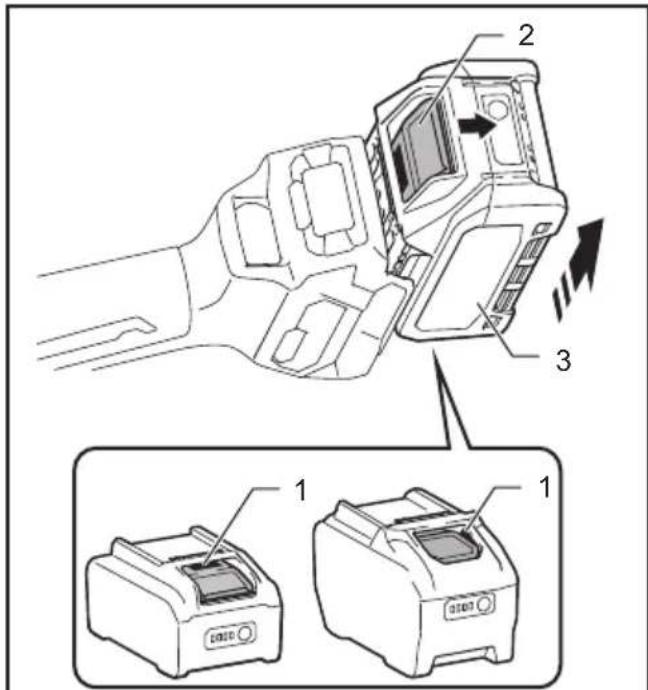
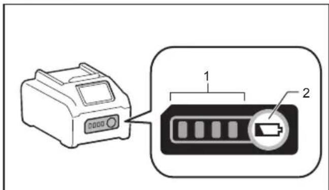
Fig.1
Fig.2
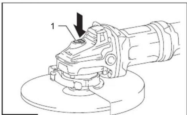
Fig.3
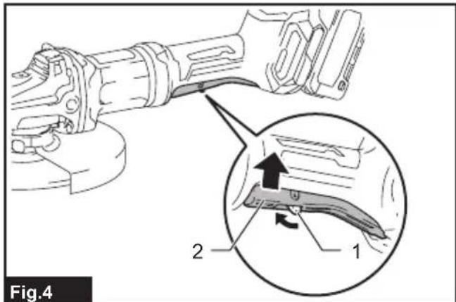
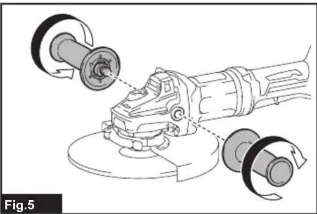
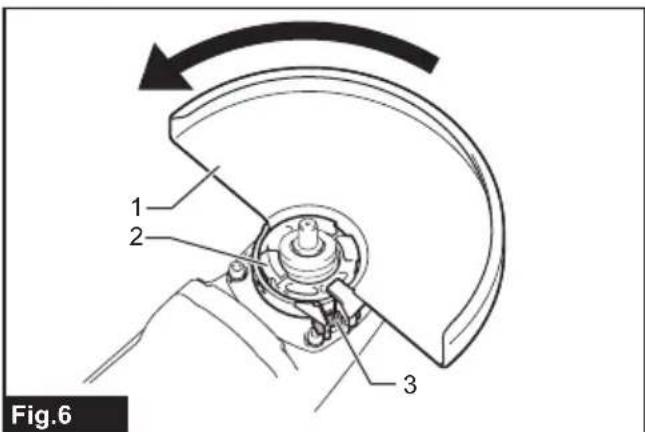
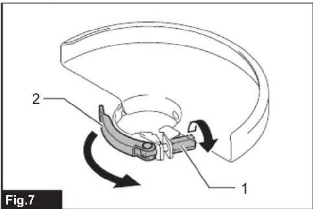
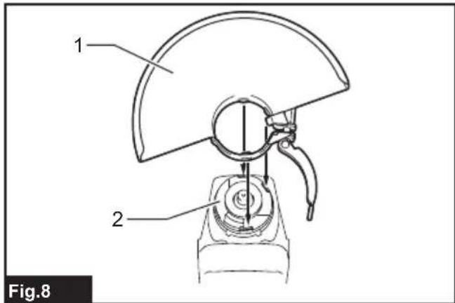
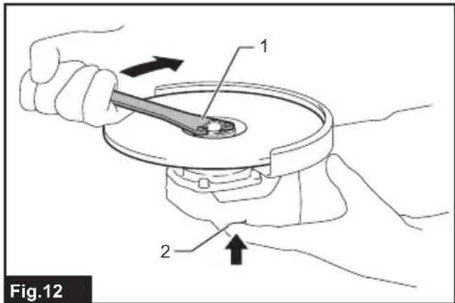
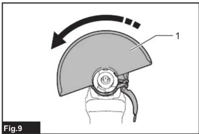
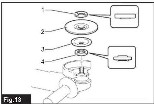
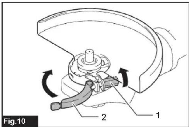
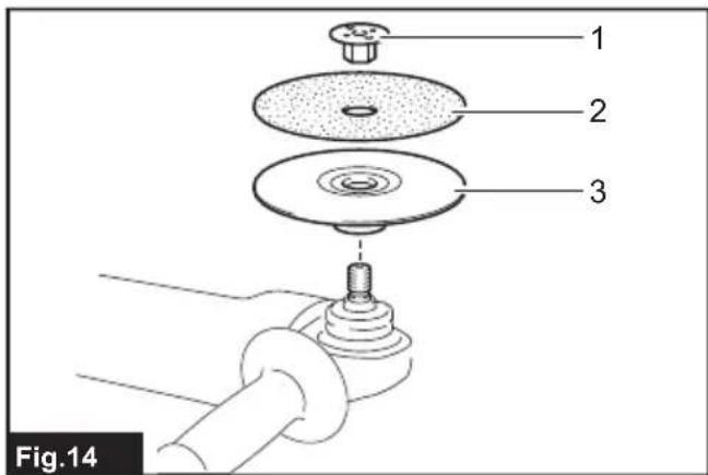

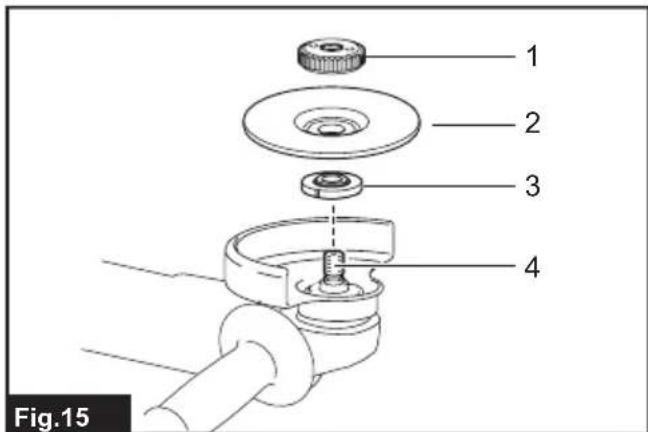
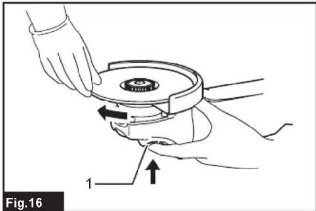
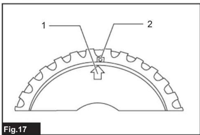
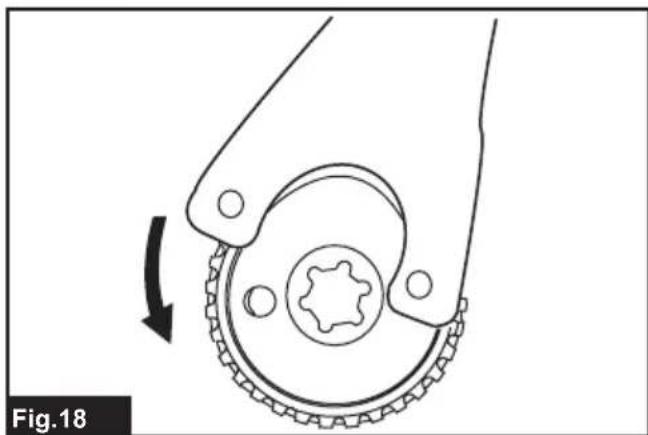
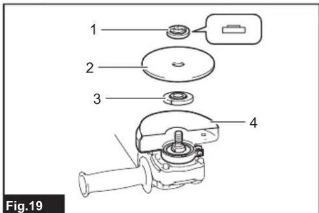
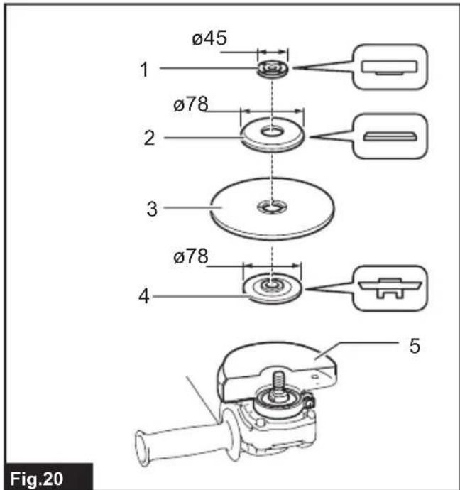
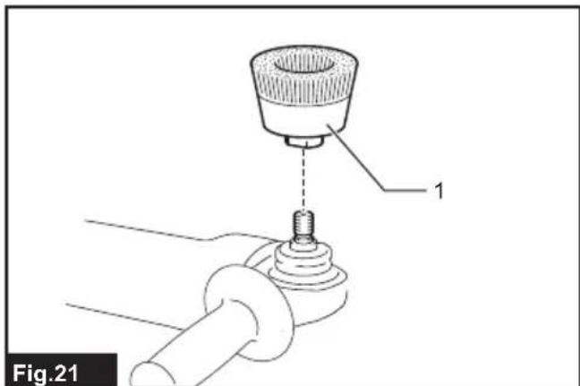
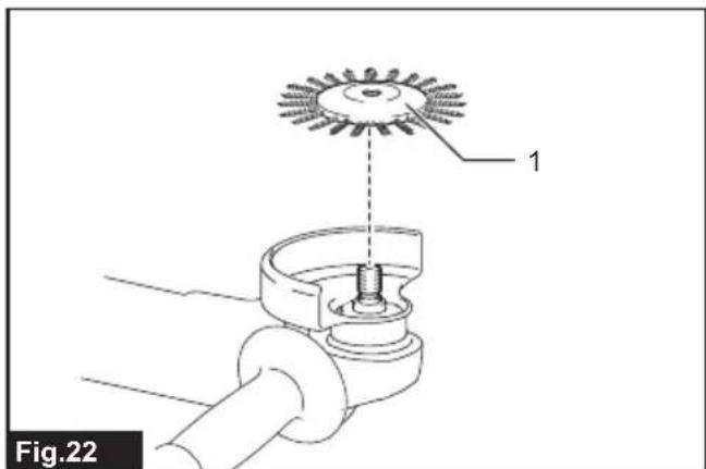
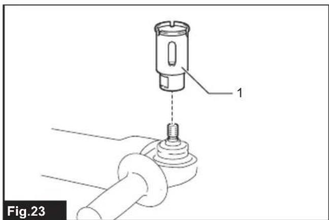
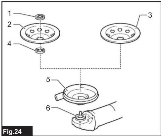
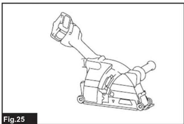

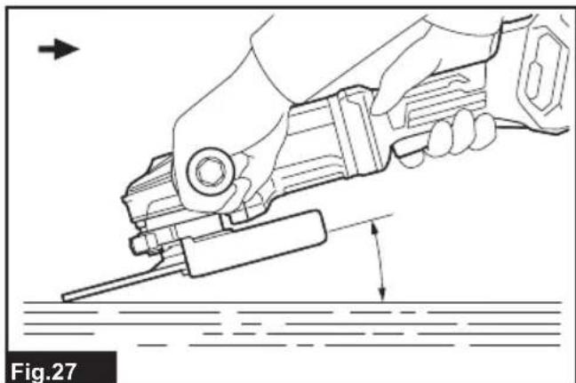
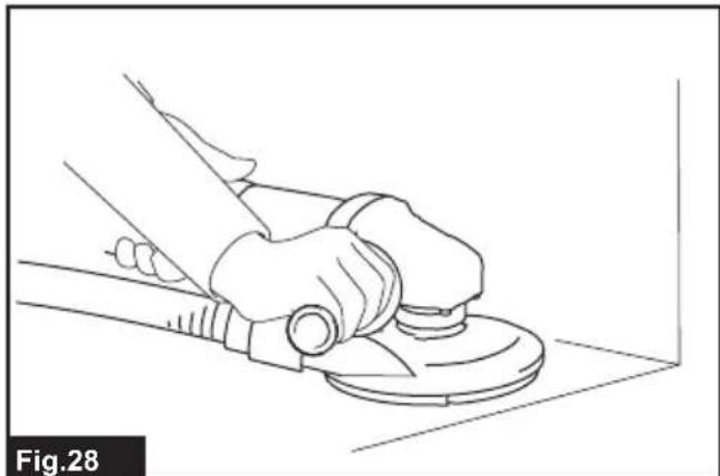
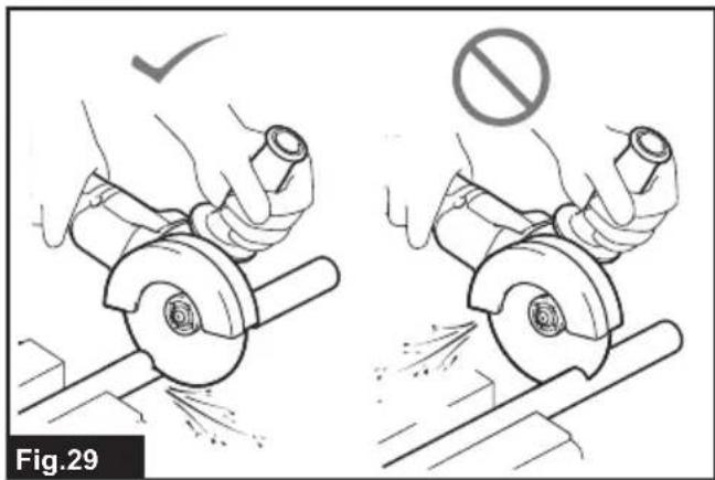
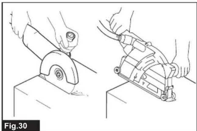
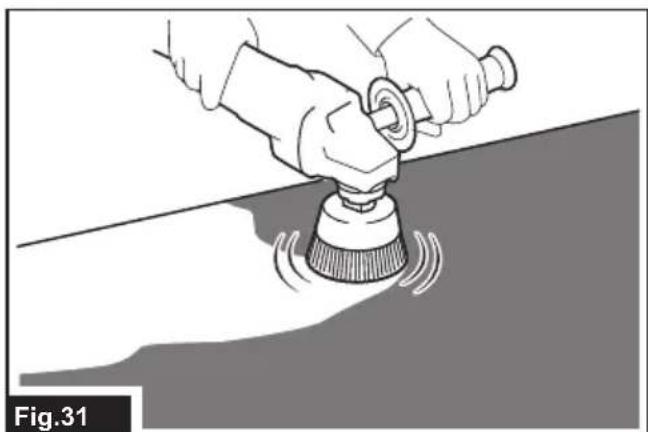
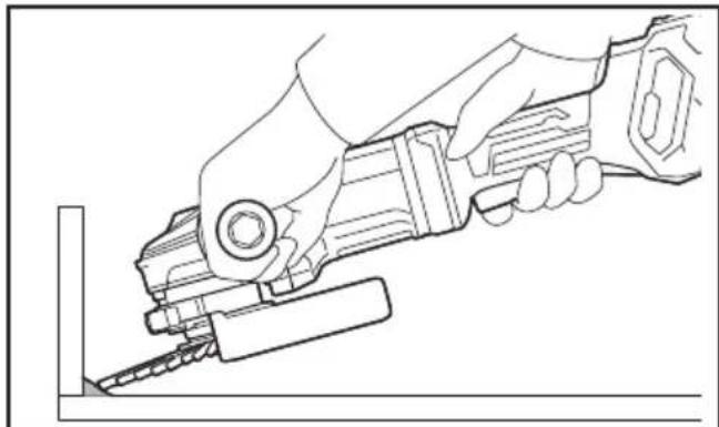
Fig.32
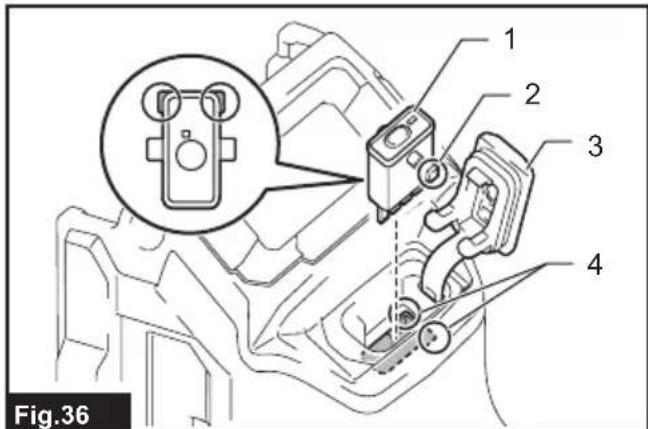
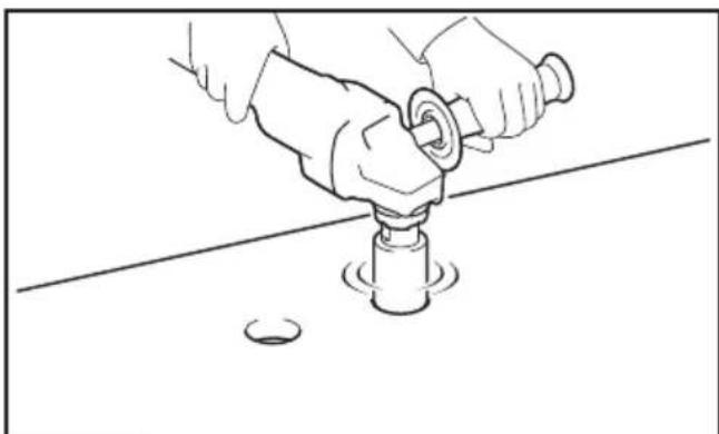
Fig.33
SPECIFICATIONS
| Model: GA037G GA038G | |||
| Applicable grinding wheel Max. w | wheel diameter 180 mm 230 mm | ||
| Max. wheel thickness 7.2 mm 6.5 mm | |||
| Applicable cut-off wheel Max. w | wheel diameter 180 mm 230 mm | ||
| Max. wheel thickness 4.0 mm 3.2 mm | |||
| Applicable wire wheel brush Max. | wheel diameter 150 mm 175 mm | ||
| Max. wheel thickness 20 mm | |||
| Spindle thread M14 or M16 or 5/8" (country specific) | |||
| Max. spindle length 26 mm | |||
| No load speed (n0) / Rated speed (n) 7,800 min | -1 | 6,600 min-1 | |
| Overall length | with BL4050F | 535 mm | |
| Net weight | 4.4 - 7.9 kg | 4.6 - 8.2 kg | |
| Rated voltage | D.C. 36 V - 40 V max | ||
Due to our continuing program of research and development, the specifications herein are subject to change without notice.
Specifications may differ from country to country.
The weight may differ depending on the attachment(s), including the battery cartridge. The lightest and heaviest combinations, according to EPTA-Procedure 01/2014, are shown in the table.
Applicable battery cartridge and charger
| Battery cartridge | BL4025 / BL4040 / BL4050F* / BL4080F* *: Recommended battery |
| Charger | DC40RA / DC40RB / DC40RC |
Some of the battery cartridges and chargers listed above may not be available depending on your region of residence.
WARNING: Only use the battery cartridges and chargers listed above. Use of any other battery cartridges and chargers may cause injury and/or fire.
Recommended cord connected power source
Portable power pack
PDC01/PDC1200
The cord connected power source(s) listed above may not be available depending on your region of residence.
Before using the cord connected power source, read instruction and cautionary markings on them.
Symbols
The followings show the symbols which may be used for the equipment. Be sure that you understand their meaning before use.


Read instruction manual.


Wear safety glasses.
Always operate with two hands.
Due to the presence of hazardous components in the equipment, waste electrical and electronic equipment, accumulators and batteries may have a negative impact on the environment and human health.
Do not dispose of electrical and electronic appliances or batteries with household waste!
In accordance with the European Directive on waste electrical and electronic equipment and on accumulators and batteries and waste accumulators and batteries, as well as their adaptation to national law, waste electrical equipment, batteries and accumulators should be stored separately and delivered to a separate collection point for municipal waste, operating in accordance with the regulations on environmental protection.
This is indicated by the symbol of the crossed-out wheeled bin placed on the equipment.
Intended use
The tool is intended for grinding, sanding, wire brushing, hole cutting and cutting of metal and stone materials without the use of water.
Noise
The typical A-weighted noise level determined according to EN62841-2-3:
| Model Sound pressure | level \( \left( {\mathrm{L}}_{\mathrm{{pA}}}\right) : \left( {\mathrm{{dB}}\left( \mathrm{A}\right) }\right) \) | Sound power level \( \left( {\mathrm{L}}_{\mathrm{{WA}}}\right) : \left( {\mathrm{{dB}}\left( \mathrm{A}\right) }\right) \) | Uncertainty (K) : (dB(A)) |
| GA037G 91 99 3 | |||
| GA038G 90 98 3 |
NOTE: The declared noise emission value(s) has been measured in accordance with a standard test method and may be used for comparing one tool with another.
NOTE: The declared noise emission value(s) may also be used in a preliminary assessment of exposure.
WARNING: Wear ear protection.
WARNING: The noise emission during actual use of the power tool can differ from the declared value(s) depending on the ways in which the tool is used especially what kind of workpiece is processed.
WARNING: Be sure to identify safety measures to protect the operator that are based on an estimation of exposure in the actual conditions of use (taking account of all parts of the operating cycle such as the times when the tool is switched off and when it is running idle in addition to the trigger time).
WARNING: Grinding thin sheets of metal or other easily vibrating structures with a large surface can result in a total noise emission much higher (up to 15 dB) than the declared noise emission values.
Set heavy flexible damping mats or such to those workpieces to prevent them from emitting sound.
Take the increased noise emission into consideration for both the risk assessment of noise exposure and selecting adequate hearing protection.
Vibration
The vibration total value (tri-axial vector sum) determined according to EN62841-2-3:
Work mode: surface grinding with normal side grip
| Model | Vibration emission \( \left( {{\mathrm{a}}_{1},{\mathrm{\;A}}_{\mathrm{G}}}\right) : \left( {\mathrm{m}/{\mathrm{s}}^{2}}\right) \) | Uncertainty (K) : \( \left( {\mathrm{m}/{\mathrm{s}}^{2}}\right) \) |
| GA037G 5.5 1.5 | ||
| GA038G 7.0 1.5 |
Work mode: surface grinding with anti vibration side grip
| Model | Vibration emission \( \left( {{\mathrm{a}}_{1,\mathrm{{AG}}}}\right) : \left( {\mathrm{m}/{\mathrm{s}}^{2}}\right) \) | Uncertainty (K) : \( \left( {\mathrm{m}/{\mathrm{s}}^{2}}\right) \) |
| GA037G 6.0 1.5 | ||
| GA038G 7.5 1.5 |
Work mode: disc sanding with normal side grip
| Model | Vibration emission \( \left( {{a}_{h},{d}_{S}}\right) : \left( {\mathrm{m}/{\mathrm{s}}^{2}}\right) \) | Uncertainty (K) : \( \left( {\mathrm{m}/{\mathrm{s}}^{2}}\right) \) |
| GA037G 3.0 1.5 | ||
| GA038G 2.5 m/s | \( {}^{2} \) or less 1.5 |
Work mode: disc sanding with anti vibration side grip
| Model | Vibration emission \( \left( {{a}_{1,{DS}}}\right) : \left( {\mathrm{m}/{\mathrm{s}}^{2}}\right) \) | Uncertainty (K) : \( \left( {\mathrm{m}/{\mathrm{s}}^{2}}\right) \) |
| GA037G 2.5 1.5 | ||
| GA038G 2.5 m/s | \( {}^{2} \) or less 1.5 |
NOTE: The declared vibration total value(s) has been measured in accordance with a standard test method and may be used for comparing one tool with another.
NOTE: The declared vibration total value(s) may also be used in a preliminary assessment of exposure.
WARNING: The vibration emission during actual use of the power tool can differ from the declared value(s) depending on the ways in which the tool is used especially what kind of workpiece is processed.
WARNING: Be sure to identify safety measures to protect the operator that are based on an estimation of exposure in the actual conditions of use (taking account of all parts of the operating cycle such as the times when the tool is switched off and when it is running idle in addition to the trigger time).
WARNING: The declared vibration emission value is used for main applications of the power tool. However if the power tool is used for other applications, the vibration emission value may be different.
EC Declaration of Conformity
For European countries only
The EC declaration of conformity is included as Annex A to this instruction manual.
SAFETYWARNINGS
General power tool safety warnings
WARNING Read all safety warnings, instructions, illustrations and specifications provided with this power tool. Failure to follow all instructions listed below may result in electric shock, fire and/or serious injury.
Save all warnings and instructions for future reference.
The term "power tool" in the warnings refers to your mains-operated (corded) power tool or battery-operated (cordless) power tool.
Cordless grinder safety warnings
Safety warnings common for grinding, sanding, wire brushing, or cutting-off operations:
- This power tool is intended to function as a grinder, sander, wire brush, hole cutter or cutoff tool. Read all safety warnings, instructions, illustrations and specifications provided with this power tool. Failure to follow all instructions listed below may result in electric shock, fire and/or serious injury.
-
Operations such as polishing are not to be performed with this power tool. Operations for which the power tool was not designed may create a hazard and cause personal injury.
-
Do not convert this power tool to operate in a way which is not specifically designed and specified by the tool manufacturer. Such a conversion may result in a loss of control and cause serious personal injury.
- Do not use accessories which are not specifically designed and specified by the tool manufacturer. Just because the accessory can be attached to your power tool, it does not assure safe operation.
- The rated speed of the accessory must be at least equal to the maximum speed marked on the power tool. Accessories running faster than their rated speed can break and fly apart.
- The outside diameter and the thickness of your accessory must be within the capacity rating of your power tool. Incorrectly sized accessories cannot be adequately guarded or controlled.
- The dimensions of the accessory mounting must fit the dimensions of the mounting hardware of the power tool. Accessories that do not match the mounting hardware of the power tool will run out of balance, vibrate excessively and may cause loss of control.
-
Do not use a damaged accessory. Before each use inspect the accessory such as abrasive wheels for chips and cracks, backing pad for cracks, tear or excess wear, wire brush for loose or cracked wires. If power tool or accessory is dropped, inspect for damage or install an undamaged accessory. After inspecting and installing an accessory, position yourself and bystanders away from the plane of the rotating accessory and run the power tool at maximum no-load speed for one minute. Damaged accessories will normally break apart during this test time.
-
Wear personal protective equipment. Depending on application, use face shield, safety goggles or safety glasses. As appropriate, wear dust mask, hearing protectors, gloves and workshop apron capable of stopping small abrasive or workpiece fragments. The eye protection must be capable of stopping flying debris generated by various applications. The dust mask or respirator must be capable of filtrating particles generated by the particular application. Prolonged exposure to high intensity noise may cause hearing loss.
- Keep bystanders a safe distance away from work area. Anyone entering the work area must wear personal protective equipment. Fragments of workpiece or of a broken accessory may fly away and cause injury beyond immediate area of operation.
- Hold the power tool by insulated gripping surfaces only, when performing an operation where the cutting tool may contact hidden wiring. Contact with a "live" wire will also make exposed metal parts of the power tool "live" and could give the operator an electric shock.
- Never lay the power tool down until the accessory has come to a complete stop. The spinning accessory may grab the surface and pull the power tool out of your control.
- Do not run the power tool while carrying it at your side. Accidental contact with the spinning accessory could snag your clothing, pulling the accessory into your body.
- Regularly clean the power tool's air vents. The motor's fan will draw the dust inside the housing and excessive accumulation of powdered metal may cause electrical hazards.
- Do not operate the power tool near flammable materials. Sparks could ignite these materials.
- Do not use accessories that require liquid coolants. Using water or other liquid coolants may result in electrocution or shock.
Kickback and related warnings:
Kickback is a sudden reaction to a pinched or snagged rotating wheel, backing pad, brush or any other accessory. Pinching or snagging causes rapid stalling of the rotating accessory which in turn causes the uncontrolled power tool to be forced in the direction opposite of the accessory's rotation at the point of the binding. For example, if an abrasive wheel is snagged or pinched by the workpiece, the edge of the wheel that is entering into the pinch point can dig into the surface of the material causing the wheel to climb out or kick out. The wheel may either jump toward or away from the operator, depending on direction of the wheel's movement at the point of pinching. Abrasive wheels may also break under these conditions. Kickback is the result of power tool misuse and/or incorrect operating procedures or conditions and can be avoided by taking proper precautions as given below.
-
Maintain a firm grip with both hands on the power tool and position your body and arms to allow you to resist kickback forces. Always use auxiliary handle, if provided, for maximum control over kickback or torque reaction during start-up. The operator can control torque reactions or kickback forces, if proper precautions are taken.
-
Never place your hand near the rotating accessory. Accessory may kickback over your hand.
- Do not position your body in the area where power tool will move if kickback occurs. Kickback will propel the tool in direction opposite to the wheel's movement at the point of snagging.
- Use special care when working corners, sharp edges, etc. Avoid bouncing and snagging the accessory. Corners, sharp edges or bouncing have a tendency to snag the rotating accessory and cause loss of control or kickback.
- Do not attach a saw chain woodcarving blade, segmented diamond wheel with a peripheral gap greater than 10mm or toothed saw blade. Such blades create frequent kickback and loss of control.
Safety warnings specific for grinding and cutting-off operations:
- Use only wheel types that are specified for your power tool and the specific guard designed for the selected wheel. Wheels for which the power tool was not designed cannot be adequately guarded and are unsafe.
- The grinding surface of centre depressed wheels must be mounted below the plane of the guard lip. An improperly mounted wheel that projects through the plane of the guard lip cannot be adequately protected.
- The guard must be securely attached to the power tool and positioned for maximum safety, so the least amount of wheel is exposed towards the operator. The guard helps to protect the operator from broken wheel fragments, accidental contact with wheel and sparks that could ignite clothing.
- Wheels must be used only for specified applications. For example: do not grind with the side of cut-off wheel. Abrasive cut-off wheels are intended for peripheral grinding, side forces applied to these wheels may cause them to shatter.
- Always use undamaged wheel flanges that are of correct size and shape for your selected wheel. Proper wheel flanges support the wheel thus reducing the possibility of wheel breakage. Flanges for cut-off wheels may be different from grinding wheel flanges.
- Do not use worn down wheels from larger power tools. A wheel intended for larger power tool is not suitable for the higher speed of a smaller tool and may burst.
- When using dual purpose wheels always use the correct guard for the application being performed. Failure to use the correct guard may not provide the desired level of guarding, which could lead to serious injury.
Additional safety warnings specific for cutting-off operations:
-
Do not "jam" the cut-off wheel or apply excessive pressure. Do not attempt to make an excessive depth of cut. Overstressing the wheel increases the loading and susceptibility to twisting or binding of the wheel in the cut and the possibility of kickback or wheel breakage.
-
Do not position your body in line with and behind the rotating wheel. When the wheel, at the point of operation, is moving away from your body, the possible kickback may propel the spinning wheel and the power tool directly at you.
- When the wheel is binding or when interrupting a cut for any reason, switch off the power tool and hold it motionless until the wheel comes to a complete stop. Never attempt to remove the cut-off wheel from the cut while the wheel is in motion otherwise kickback may occur. Investigate and take corrective action to eliminate the cause of wheel binding.
- Do not restart the cutting operation in the workpiece. Let the wheel reach full speed and carefully re-enter the cut. The wheel may bind, walk up or kickback if the power tool is restarted in the workpiece.
- Support panels or any oversized workpiece to minimize the risk of wheel pinching and kickback. Large workpieces tend to sag under their own weight. Supports must be placed under the workpiece near the line of cut and near the edge of the workpiece on both sides of the wheel.
- Use extra caution when making a "pocket cut" into existing walls or other blind areas. The protruding wheel may cut gas or water pipes, electrical wiring or objects that can cause kickback.
- Do not attempt to do curved cutting. Overstressing the wheel increases the loading and susceptibility to twisting or binding of the wheel in the cut and the possibility of kickback or wheel breakage, which can lead to serious injury.
- Before using a segmented diamond wheel, make sure that the diamond wheel has the peripheral gap between segments of 10mm or less, only with a negative rake angle.
Safety warnings specific for sanding operations:
- Use proper sized sanding disc paper. Follow manufacturers recommendations, when selecting sanding paper. Larger sanding paper extending too far beyond the sanding pad presents a laceration hazard and may cause snagging, tearing of the disc or kickback.
Safety warnings specific for wire brushing operations:
- Be aware that wire bristles are thrown by the brush even during ordinary operation. Do not overstress the wires by applying excessive load to the brush. The wire bristles can easily penetrate light clothing and/or skin.
- If the use of a guard is specified for wire brushing, do not allow any interference of the wire wheel or brush with the guard. Wire wheel or brush may expand in diameter due to work load and centrifugal forces.
Additional SafetyWarnings:
- When using depressed centre grinding wheels, be sure to use only fiberglass-reinforced wheels.
-
NEVER USE Stone Cup type wheels with this grinder. This grinder is not designed for these types of wheels and the use of such a product may result in serious personal injury.
-
Be careful not to damage the spindle, the flange (especially the installing surface) or the lock nut. Damage to these parts could result in wheel breakage.
- Make sure the wheel is not contacting the workpiece before the switch is turned on.
- Before using the tool on an actual workpiece, let it run for a while. Watch for vibration or wobbling that could indicate poor installation or a poorly balanced wheel.
- Use the specified surface of the wheel to perform the grinding.
- Do not leave the tool running. Operate the tool only when hand-held.
- Do not touch the workpiece immediately after operation; it may be extremely hot and could burn your skin.
- Do not touch accessories immediately after operation; it may be extremely hot and could burn your skin.
- Observe the instructions of the manufacturer for correct mounting and use of wheels. Handle and store wheels with care.
- Do not use separate reducing bushings or adaptors to adapt large hole abrasive wheels.
- Use only flanges specified for this tool.
- For tools intended to be fitted with threaded hole wheel, ensure that the thread in the wheel is long enough to accept the spindle length.
- Check that the workpiece is properly supported.
- Pay attention that the wheel continues to rotate after the tool is switched off.
- If working place is extremely hot and humid, or badly polluted by conductive dust, use a short-circuit breaker (30 mA) to assure operator safety.
- Do not use the tool on any materials containing asbestos.
- When use cut-off wheel, always work with the dust collecting wheel guard if required by domestic regulation.
- Cutting discs must not be subjected to any lateral pressure.
- Do not use cloth work gloves during operation. Fibers from cloth gloves may enter the tool, which causes tool breakage.
- Before operation, make sure that there is no buried object such as electric pipe, water pipe or gas pipe in the workpiece. Otherwise, it may cause an electric shock, electrical leakage or gas leak.
- If a blotter is attached to the wheel, do not remove it. The diameter of the blotter must be larger than the lock nut, outer flange, and inner flange.
- Before installing a grinding wheel, always check that the blotter part does not have any abnormalities such as chips or cracks.
- Tighten the lock nut properly. Overtightening the wheel can cause breakage and insufficient tightening can cause fluttering.
SAVE THESE INSTRUCTIONS.
WARNING: DO NOT let comfort or familiarity with product (gained from repeated use) replace strict adherence to safety rules for the subject product. MISUSE or failure to follow the safety rules stated in this instruction manual may cause serious personal injury.
Important safety instructions for battery cartridge
- Before using battery cartridge, read all instructions and cautionary markings on (1) battery charger, (2) battery, and (3) product using battery.
- Do not disassemble or tamper with the battery cartridge. It may result in a fire, excessive heat, or explosion.
- If operating time has become excessively shorter, stop operating immediately. It may result in a risk of overheating, possible burns and even an explosion.
- If electrolyte gets into your eyes, rinse them out with clear water and seek medical attention right away. It may result in loss of your eyesight.
- Do not short the battery cartridge:
(1) Do not touch the terminals with any conductive material.
(2) Avoid storing battery cartridge in a container with other metal objects such as nails, coins, etc.
(3) Do not expose battery cartridge to water or rain.
A battery short can cause a large current flow, overheating, possible burns and even a breakdown.
- Do not store and use the tool and battery cartridge in locations where the temperature may reach or exceed 50^ (122°F).
- Do not incinerate the battery cartridge even if it is severely damaged or is completely worn out. The battery cartridge can explode in a fire.
-
Do not nail, cut, crush, throw, drop the battery cartridge, or hit against a hard object to the battery cartridge. Such conduct may result in a fire, excessive heat, or explosion.
-
Do not use a damaged battery.
- The contained lithium-ion batteries are subject to the Dangerous Goods Legislation requirements.
For commercial transports e.g. by third parties, forwarding agents, special requirement on packaging and labeling must be observed.
For preparation of the item being shipped, consulting an expert for hazardous material is required.
Please also observe possibly more detailed national regulations.
Tape or mask off open contacts and pack up the battery in such a manner that it cannot move around in the packaging.
11. When disposing the battery cartridge, remove it from the tool and dispose of it in a safe place. Follow your local regulations relating to disposal of battery.
- Use the batteries only with the products specified by Makita. Installing the batteries to non-compliant products may result in a fire, excessive heat, explosion, or leak of electrolyte.
- If the tool is not used for a long period of time, the battery must be removed from the tool.
- During and after use, the battery cartridge may take on heat which can cause burns or low temperature burns. Pay attention to the handling of hot battery cartridges.
- Do not touch the terminal of the tool immediately after use as it may get hot enough to cause burns.
- Do not allow chips, dust, or soil stuck into the terminals, holes, and grooves of the battery cartridge. It may cause heating, catching fire, burst and malfunction of the tool or battery cartridge, resulting in burns or personal injury.
- Unless the tool supports the use near high-voltage electrical power lines, do not use the battery cartridge near a high-voltage electrical power lines. It may result in a malfunction or breakdown of the tool or battery cartridge.
- Keep the battery away from children.
SAVE THESE INSTRUCTIONS.
CAUTION: Only use genuine Makita batteries. Use of non-genuine Makita batteries, or batteries that have been altered, may result in the battery bursting causing fires, personal injury and damage. It will also void the Makita warranty for the Makita tool and charger.
Tips for maintaining maximum battery life
- Charge the battery cartridge before completely discharged. Always stop tool operation and charge the battery cartridge when you notice less tool power.
- Never recharge a fully charged battery cartridge. Overcharging shortens the battery service life.
- Charge the battery cartridge with room temperature at 10^ - 40^ (50°F - 104°F). Let a hot battery cartridge cool down before charging it.
- When not using the battery cartridge, remove it from the tool or the charger.
- Charge the battery cartridge if you do not use it for a long period (more than six months).
Important safety instructions for wireless unit
- Do not disassemble or tamper with the wireless unit.
- Keep the wireless unit away from young children. If accidentally swallowed, seek medical attention immediately.
- Use the wireless unit only with Makita tools.
- Do not expose the wireless unit to rain or wet conditions.
-
Do not use the wireless unit in places where the temperature exceeds 50^ (122^) .
-
Do not operate the wireless unit in places where medical instruments, such as heart pace makers are nearby.
- Do not operate the wireless unit in places where automated devices are nearby. If operated, automated devices may develop malfunction or error.
- Do not operate the wireless unit in places under high temperature or places where static electricity or electrical noise could be generated.
- The wireless unit can produce electromagnetic fields (EMF) but they are not harmful to the user.
- The wireless unit is an accurate instrument. Be careful not to drop or strike the wireless unit.
- Avoid touching the terminal of the wireless unit with bare hands or metallic materials.
- Always remove the battery on the product when installing the wireless unit into it.
- When opening the lid of the slot, avoid the place where dust and water may come into the slot. Always keep the inlet of the slot clean.
- Always insert the wireless unit in the correct direction.
- Do not press the wireless activation button on the wireless unit too hard and/or press the button with an object with a sharp edge.
- Always close the lid of the slot when operating.
- Do not remove the wireless unit from the slot while the power is being supplied to the tool. Doing so may cause a malfunction of the wireless unit.
- Do not remove the sticker on the wireless unit.
- Do not put any sticker on the wireless unit.
- Do not leave the wireless unit in a place where static electricity or electrical noise could be generated.
- Do not leave the wireless unit in a place subject to high heat, such as a car sitting in the sun.
- Do not leave the wireless unit in a dusty or powdery place or in a place corrosive gas could be generated.
- Sudden change of the temperature may bedew the wireless unit. Do not use the wireless unit until the dew is completely dried.
- When cleaning the wireless unit, gently wipe with a dry soft cloth. Do not use benzine, thinner, conductive grease or the like.
- When storing the wireless unit, keep it in the supplied case or a static-free container.
- Do not insert any devices other than Makita wireless unit into the slot on the tool.
- Do not use the tool with the lid of the slot damaged. Water, dust, and dirt come into the slot may cause malfunction.
- Do not pull and/or twist the lid of the slot more than necessary. Restore the lid if it comes off from the tool.
- Replace the lid of the slot if it is lost or damaged.
SAVE THESE INSTRUCTIONS.
FUNCTIONAL DESCRIPTION
CAUTION: Always be sure that the tool is switched off and the battery cartridge is removed before adjusting or checking function on the tool.
Installing or removing battery cartridge
CAUTION: Always switch off the tool before installing or removing of the battery cartridge.
CAUTION: Hold the tool and the battery cartridge firmly when installing or removing battery cartridge. Failure to hold the tool and the battery cartridge firmly may cause them to slip off your hands and result in damage to the tool and battery cartridge and a personal injury.
Fig.1: 1. Red indicator 2. Button 3. Battery cartridge
To remove the battery cartridge, slide it from the tool while sliding the button on the front of the cartridge.
To install the battery cartridge, align the tongue on the battery cartridge with the groove in the housing and slip it into place. Insert it all the way until it locks in place with a little click. If you can see the red indicator as shown in the figure, it is not locked completely.
CAUTION: Always install the battery cartridge fully until the red indicator cannot be seen. If not, it may accidentally fall out of the tool, causing injury to you or someone around you.
CAUTION: Do not install the battery cartridge forcibly. If the cartridge does not slide in easily, it is not being inserted correctly.
Indicating the remaining battery capacity
Press the check button on the battery cartridge to indicate the remaining battery capacity. The indicator lamps light up for a few seconds.
Fig.2: 1. Indicator lamps 2. Check button
| Indicator lamps Remaining | capacity | ||
| Lighted Off | Blinking | ||
| 75% to 100% | |||
| 50% to 75% | |||
| 25% to 50% | |||
| 0% to 25% | |||
| Charge the battery. | |||
| The battery may have malfunctioned. | |||
NOTE: Depending on the conditions of use and the ambient temperature, the indication may differ slightly from the actual capacity.
NOTE: The first (far left) indicator lamp will blink when the battery protection system works.
Tool / battery protection system
The tool is equipped with a tool/battery protection system. This system automatically cuts off power to the motor to extend tool and battery life. The tool will automatically stop during operation if the tool or battery is placed under one of the following conditions:
Overload protection
When the tool/battery is operated in a manner that causes it to draw an abnormally high current, the tool automatically stops without any indication. In this situation, turn the tool off and stop the application that caused the tool to become overloaded. Then turn the tool on to restart.
Overheat protection
When the tool/battery is overheated, the tool stops automatically. Let the tool cool down before turning the tool on again.
Overdischarge protection
When the battery capacity is not enough, the tool stops automatically. In this case, remove the battery from the tool and charge the battery.
Protections against other causes
Protection system is also designed for other causes that could damage the tool and allows the tool to stop automatically. Take all the following steps to clear the causes, when the tool has been brought to a temporary halt or stop in operation.
- Turn the tool off, and then turn it on again to restart.
- Charge the battery(ies) or replace it/them with recharged battery(ies).
- Let the tool and battery(ies) cool down.
If no improvement can be found by restoring protection system, then contact your local Makita Service Center.
Shaft lock

WARNING: Never actuate the shaft lock when the spindle is moving. It may cause serious injury on the tool damage.
Press the shaft lock to prevent spindle rotation when installing or removing accessories.
Fig.3: 1. Shaft lock
Switch action
CAUTION: Before installing the battery cartridge into the tool, always check to see that the switch lever actuates properly and returns to the "OFF" position when released.
CAUTION: For your safety, this tool is equipped with lock-off lever which prevents the tool from unintended starting. NEVER use the tool if it runs when you simply pull the switch lever without folding the lock-off lever. Return the tool to our authorized service center for proper repairs BEFORE further usage.
CAUTION: Do not pull the switch lever hard without folding the lock-off lever. This can cause switch breakage.
CAUTION: NEVER tape down or defeat purpose and function of lock-off lever.
To prevent the switch lever from being accidentally pulled, a lock-off lever is provided.
To start the tool, fold the lock-off lever and then pull the switch lever.
To stop the tool, release the switch lever.
Fig.4: 1. Lock-off lever 2. Switch lever
Accidental re-start preventive function
When installing the battery cartridge while the switch is ON, the tool does not start.
To start the tool, turn off the switch, and turn it on again.
Active Feedback sensing Technology
The tool electronically detects situations where the wheel or accessory may be at risk to be bound. In the situation, the tool is automatically shut off to prevent further rotation of the spindle (it does not prevent kickback).
To restart the tool, switch off the tool first, remove the cause of sudden drop in the rotation speed, and then turn the tool on.
Soft start feature
Soft start feature reduces starting reaction.
Electric brake
Electric brake is activated after the tool is switched off. The brake does not work when the power supply is shut down, such as the battery is removed accidentally, with the switch still on.
ASSEMBLY
CAUTION: Always be sure that the tool is switched off and the battery cartridge is removed before adjusting or checking function on the tool.
Installing side grip (handle)
CAUTION: Always be sure that the side grip is installed securely before operation.
Screw the side grip securely on the position of the tool as shown in the figure.
Fig.5
Installing or removing wheel guard (For depressed center wheel, flap disc, flex wheel, wire wheel brush / abrasive cut-off wheel, diamond wheel)
WARNING: When using a depressed center wheel, flap disc, flex wheel or wire wheel brush, the wheel guard must be fitted on the tool so that the closed side of the guard always points toward the operator.
WARNING: When using an abrasive cut-off / diamond wheel, be sure to use only the special wheel guard designed for use with cut-off wheels.
For tool with locking screw type wheel guard
Mount the wheel guard with the protrusions on the wheel guard band aligned with the notches on the bearing box. Then rotate the wheel guard to such an angle that it can protect the operator according to work. Be sure to tighten the screw securely.
To remove wheel guard, follow the installation procedure in reverse.
Fig.6: 1.Wheel guard 2.Bearing box 3.Screw
For tool with clamp lever type wheel guard
Loosen the nut, and then pull the lever in the direction of the arrow.
Fig.7: 1. Nut 2. Lever
Mount the wheel guard with the protrusions on the wheel guard band aligned with the notches on the bearing box. Then rotate the wheel guard to such an angle that it can protect the operator according to work.
Fig.8: 1.Wheel guard 2.Bearing box
Fig.9: 1.Wheel guard
Securely tighten the nut using a spanner, and then close the lever in direction of the arrow to fasten the wheel guard. If the lever is too tight or too loose to fasten the wheel guard, open the lever and then loosen or tighten the nut using the spanner to adjust the tightening of the wheel guard band.
Fig.10: 1. Nut 2. Lever
To remove wheel guard, follow the installation procedure in reverse.
Installing or removing depressed center wheel or flap disc
Optional accessory
WARNING: When using a depressed center wheel or flap disc, the wheel guard must be fitted on the tool so that the closed side of the guard always points toward the operator.
WARNING: Make sure that the mounting part of the inner flange fits into the inner diameter of the depressed center wheel / flap disc perfectly. Mounting the inner flange on the wrong side may result in the dangerous vibration.
Mount the inner flange onto the spindle.
Make sure to fit the dented part of the inner flange onto the straight part at the bottom of the spindle.
Fit the wheel/disc on the inner flange and screw the lock nut with its protrusion facing downward (facing towards the wheel).
Fig.11: 1. Lock nut 2. Depressed center wheel
3. Inner flange 4. Mounting part
To tighten the lock nut, press the shaft lock firmly so that the spindle cannot revolve, then use the lock nut wrench and securely tighten clockwise.
Fig.12: 1. Lock nut wrench 2. Shaft lock
To remove the wheel, follow the installation procedure in reverse.
Installing or removing flex wheel
Optional accessory
WARNING: Always use supplied guard when flex wheel is on the tool. Wheel can shatter during use and guard helps to reduce chances of personal injury.
Fig.13: 1.Lock nut 2.Flex wheel 3.Back up pad 4. Inner flange
Follow instructions for depressed center wheel but also use back up pad over wheel.
Installing or removing abrasive disc
Optional accessory
Fig.14: 1. Sanding lock nut 2. Abrasive disc 3. Rubber pad
- Mount the rubber pad onto the spindle.
- Fit the disc on the rubber pad and screw the sanding lock nut onto the spindle.
- Hold the spindle with the shaft lock, and securely tighten the sanding lock nut clockwise with the lock nut wrench.
To remove the disc, follow the installation procedure in reverse.
NOTE: Use sander accessories specified in this manual. These must be purchased separately.
Installing or removing Ezynut
Optional accessory
Only for tools with M14 spindle thread.
Mount inner flange, abrasive wheel and Ezynut onto the spindle so that Makita Logo on Ezynut faces outside.
Fig.15: 1. Ezynut 2. Abrasive wheel 3. Inner flange 4. Spindle
Press shaft lock firmly and tighten Ezynut by turning the abrasive wheel clockwise as far as it turns.
Fig.16: 1. Shaft lock
To loosen the Ezynut, turn the outside ring of Ezynut counterclockwise.
NOTE: Ezynut can be loosened by hand as long as the arrow points the notch. Otherwise a lock nut wrench is required to loosen it. Insert one pin of the wrench into a hole and turn Ezynut counterclockwise.
Fig.17: 1. Arrow 2. Notch
Fig.18
Installing abrasive cut-off / diamond wheel
Optional accessory
WARNING: When using an abrasive cut-off diamond wheel, be sure to use only the special wheel guard designed for use with cut-off wheels.
WARNING: NEVER use cut-off wheel for side grinding.
Mount the inner flange onto the spindle.
Fit the wheel / disc on the inner flange and screw the lock nut onto the spindle.
Fig.19: 1. Lock nut 2. Abrasive cut-off wheel / diamond wheel 3. Inner flange 4. Wheel guard for abrasive cut-off wheel / diamond wheel
For Australia and New Zealand
Fig.20: 1. Lock nut 2. Outer flange 78 3. Abrasive cut-off wheel / diamond wheel 4. Inner flange 78 5. Wheel guard for abrasive cut-off wheel / diamond wheel
Installing wire cup brush
Optional accessory
CAUTION: Do not use brush that is damaged, or which is out of balance. Use of damaged brush could increase potential for injury from contact with broken brush wires.
Place the tool upside down to allow easy access to the spindle.
Remove any accessories on spindle. Thread wire cup brush onto spindle and tighten with supplied wrench.
Fig.21: 1. Wire cup brush
Installing wire wheel brush
Optional accessory
CAUTION: Do not use wire wheel brush that is damaged, or which is out of balance. Use of damaged wire wheel brush could increase potential for injury from contact with broken wires.
CAUTION: ALWAYS use guard with wire wheel brushes, assuring diameter of wheel fits inside guard. Wheel can shatter during use and guard helps to reduce chances of personal injury.
Place the tool upside down to allow easy access to the spindle. Remove any accessories on spindle. Thread wire wheel brush onto spindle and tighten with the wrenches.
Fig.22:1.Wire wheel brush
Installing hole cutter
Optional accessory
Place the tool upside down to allow easy access to the spindle. Remove any accessories on the spindle. Thread the hole cutter onto the spindle, and tighten it with the supplied wrench.
Fig.23: 1.Hole cutter
Installing dust collecting wheel guard for grinding
Optional accessory
With optional accessories, you can use this tool for planing concrete surface.
CAUTION: Dust collecting wheel guard for grinding is only for use in planing concrete surface with a cup-type diamond wheel. Do not use this guard with any other cutting accessory or for any other purpose.
CAUTION: Before operation, make sure that a vacuum cleaner is connected to the tool and turned on.
Place the tool upside down and install the dust collecting wheel guard.
Mount the inner flange onto the spindle.
Fit the cup-type diamond wheel on the inner flange and tighten the lock nut onto the spindle.
Fig.24: 1. Lock nut 2. Cup-type diamond wheel 3. Hubbed cup-type diamond wheel 4. Inner flange 5. Dust collecting wheel guard 6. Bearing box
NOTE: For information how to install the dust collecting wheel guard, refer to the manual of the dust collecting wheel guard.
Installing dust collecting wheel guard for cutting-off
Optional accessory
With optional accessories, you can use this tool for cutting stone materials.
Fig.25
NOTE: For information how to install the dust collecting wheel guard, refer to the manual of the dust collecting wheel guard.
Connecting a vacuum cleaner
Optional accessory
WARNING: Never vacuum metal particles created by grinding/cutting/sanding operation. Metal particles created by such operation are so hot that they ignite dust and the filter inside the vacuum cleaner.
To avoid dusty environment caused by masonry cutting, use a dust collecting wheel guard and a vacuum cleaner.
Refer to the instruction manual attached to the dust collecting wheel guard for assembling and using it.
Fig.26: 1. Dust collecting wheel guard 2. Hose of the vacuum cleaner
OPERATION
WARNING: It should never be necessary to force the tool. The weight of the tool applies adequate pressure. Forcing and excessive pressure could cause dangerous wheel breakage.
WARNING: ALWAYS replace wheel if tool is dropped while grinding.
WARNING: NEVER hit the workpiece with the wheel.
WARNING: Avoid bouncing and snagging the wheel, especially when working corners, sharp edges etc. This can cause loss of control and kickback.
WARNING: NEVER use tool with wood cutting blades and other saw blades. Such blades when used on a grinder frequently kick and cause loss of control leading to personal injury.
CAUTION: Never switch on the tool when it is in contact with the workpiece, it may cause an injury to operator.
CAUTION: Always wear safety goggles or a face shield during operation.
CAUTION: After operation, always switch off the tool and wait until the wheel has come to a complete stop before putting the tool down.
CAUTION: ALWAYS hold the tool firmly with one hand on housing and the other on the side grip (handle).
NOTE: A dual purpose wheel can be used for both grinding and cutting-off operations.
Refer to the "Grinding and sanding operation" for grinding operation, and refer to the "Operation with abrasive cut-off / diamond wheel" for cutting-off operation.
Grinding and sanding operation
Fig.27
Turn the tool on and then apply the wheel or disc to the workpiece. In general, keep the edge of the wheel or disc at an angle of about 15^ to the workpiece surface. During the break-in period with a new wheel, do not work the grinder in forward direction or it may cut into the workpiece. Once the edge of the wheel has been rounded off by use, the wheel may be worked in both forward and backward direction.
Usage example: operation with cup-type diamond wheel Fig.28
Keep the tool horizontally and apply the entire cup-type diamond wheel to the workpiece surface.
Operation with abrasive cut-off / diamond wheel
Optional accessory
WARNING: Do not "jam" the wheel or apply excessive pressure. Do not attempt to make an excessive depth of cut. Overstressing the wheel increases the loading and susceptibility to twisting or binding of the wheel in the cut and the possibility of kickback, wheel breakage and overheating of the motor may occur.
WARNING: Do not start the cutting operation in the workpiece. Let the wheel reach full speed and carefully enter into the cut moving the tool forward over the workpiece surface. The wheel may bind, walk up or kickback if the power tool is started in the workpiece.
WARNING: During cutting operations, never change the angle of the wheel. Placing side pressure on the cut-off wheel (as in grinding) will cause the wheel to crack and break, causing serious personal injury.
WARNING: A diamond wheel shall be operated perpendicular to the material being cut.
Usage example: operation with abrasive cut-off wheel
Fig.29
Usage example: operation with diamond wheel
Fig.30
Operation with wire cup brush
Optional accessory
CAUTION: Check operation of brush by running tool with no load, insuring that no one is in front of or in line with brush.
NOTICE: Avoid applying too much pressure which causes over bending of wires when using the wire cup brush. It may lead to premature breakage.
Usage example: operation with wire cup brush
Fig.31
Operation with wire wheel brush
Optional accessory
CAUTION: Check operation of wire wheel brush by running tool with no load, insuring that no one is in front of or in line with the wire wheel brush.
NOTICE: Avoid applying too much pressure which causes over bending of wires when using wire wheel brush. It may lead to premature breakage.
Usage example: operation with wire wheel brush
Fig.32
Operation with hole cutter
Optional accessory
CAUTION: Check operation of the hole cutter by running the tool with no load, insuring that no one is in front of the hole cutter.
NOTICE: Do not tilt the tool during operation. It may lead to premature breakage.
Usage example: operation with hole cutter
Fig.33
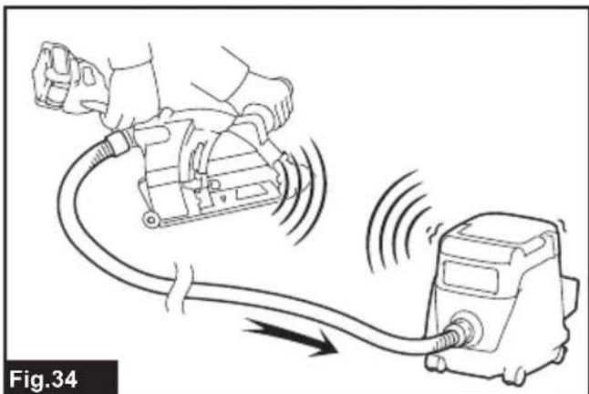
WIRELESS ACTIVATION FUNCTION
What you can do with the wireless activation function
The wireless activation function enables clean and comfortable operation. By connecting a supported vacuum cleaner to the tool, you can run the vacuum cleaner automatically along with the switch operation of the tool.
Fig.34
To use the wireless activation function, prepare following items:
- A wireless unit (optional accessory)
- A vacuum cleaner which supports the wireless activation function
The overview of the wireless activation function setting is as follows. Refer to each section for detail procedures.
- Installing the wireless unit
- Tool registration for the vacuum cleaner
- Starting the wireless activation function
Installing the wireless unit
Optional accessory
CAUTION: Place the tool on a flat and stable surface when installing the wireless unit.
NOTICE: Clean the dust and dirt on the tool before installing the wireless unit. Dust or dirt may cause malfunction if it comes into the slot of the wireless unit.
NOTICE: To prevent the malfunction caused by static, touch a static discharging material, such as a metal part of the tool, before picking up the wireless unit.
NOTICE: When installing the wireless unit, always be sure that the wireless unit is inserted in the correct direction and the lid is completely closed.
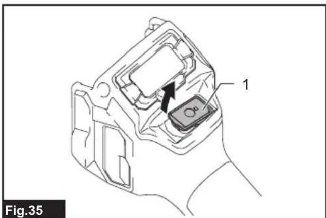
- Open the lid on the tool as shown in the figure.
Fig.35:1.Lid - Insert the wireless unit to the slot and then close the lid.
When inserting the wireless unit, align the projections with the recessed portions on the slot.
Fig.36: 1. Wireless unit 2. Projection 3. Lid
- Recessed portion
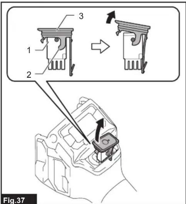
When removing the wireless unit, open the lid slowly. The hooks on the back of the lid will lift the wireless unit as you pull up the lid.
Fig.37: 1. Wireless unit 2. Hook 3. Lid
After removing the wireless unit, keep it in the supplied case or a static-free container.
NOTICE: Always use the hooks on the back of the lid when removing the wireless unit. If the hooks do not catch the wireless unit, close the lid completely and open it slowly again.
Tool registration for the vacuum cleaner
NOTE: A Makita vacuum cleaner supporting the wireless activation function is required for the tool registration.
NOTE: Finish installing the wireless unit to the tool before starting the tool registration.
NOTE: During the tool registration, do not pull the switch trigger or turn on the power switch on the vacuum cleaner.
NOTE: Refer to the instruction manual of the vacuum cleaner, too.
If you wish to activate the vacuum cleaner along with the switch operation of the tool, finish the tool registration beforehand.
- Install the batteries to the vacuum cleaner and the tool.
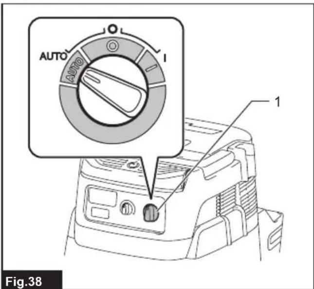
- Set the stand-by switch on the vacuum cleaner to "AUTO".
Fig.38: 1. Stand-by switch
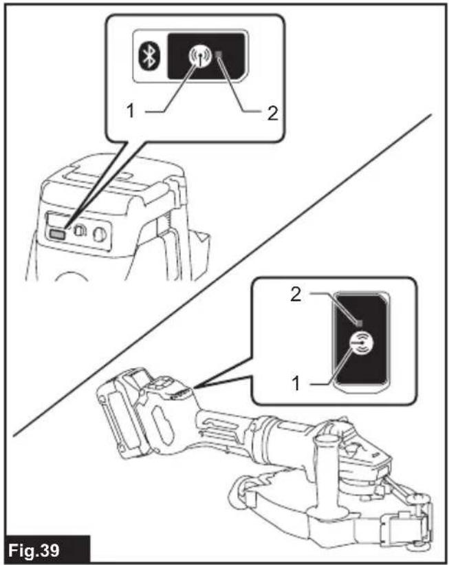
- Press the wireless activation button on the vacuum cleaner for 3 seconds until the wireless activation lamp blinks in green. And then press the wireless activation button on the tool in the same way.
Fig.39: 1. Wireless activation button 2. Wireless activation lamp
If the vacuum cleaner and the tool are linked successfully, the wireless activation lamps will light up in green for 2 seconds and start blinking in blue.
NOTE: The wireless activation lamps finish blinking in green after 20 seconds elapsed. Press the wireless activation button on the tool while the wireless activation lamp on the cleaner is blinking. If the wireless activation lamp does not blink in green, push the wireless activation button briefly and hold it down again.
NOTE: When performing two or more tool registrations for one vacuum cleaner, finish the tool registration one by one.
Starting the wireless activation function
NOTE: Finish the tool registration for the vacuum cleaner prior to the wireless activation.
NOTE: Refer to the instruction manual of the vacuum cleaner, too.
After registering a tool to the vacuum cleaner, the vacuum cleaner will automatically runs along with the switch operation of the tool.
- Install the wireless unit to the tool.
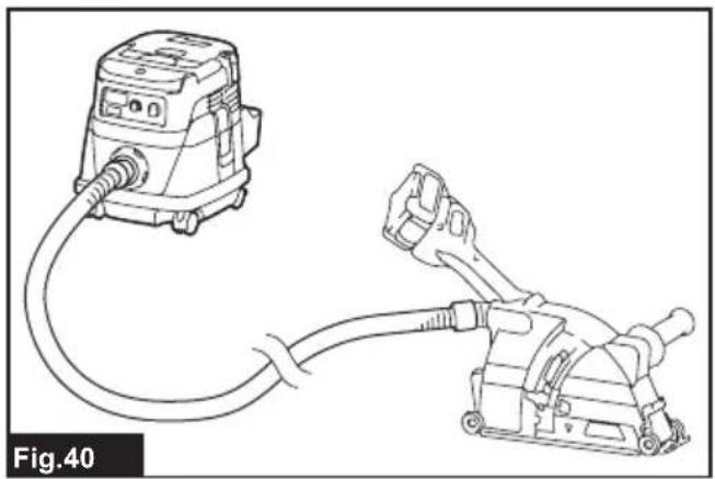
- Connect the hose of the vacuum cleaner with the tool.
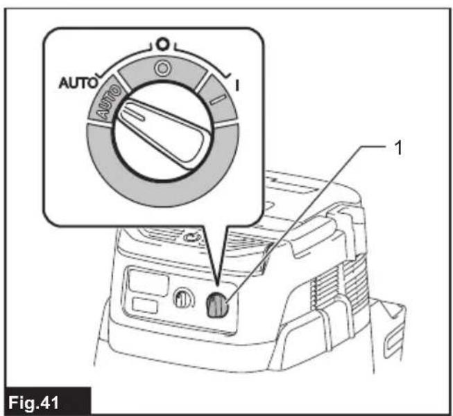
Fig.40 - Set the stand-by switch on the vacuum cleaner to "AUTO".
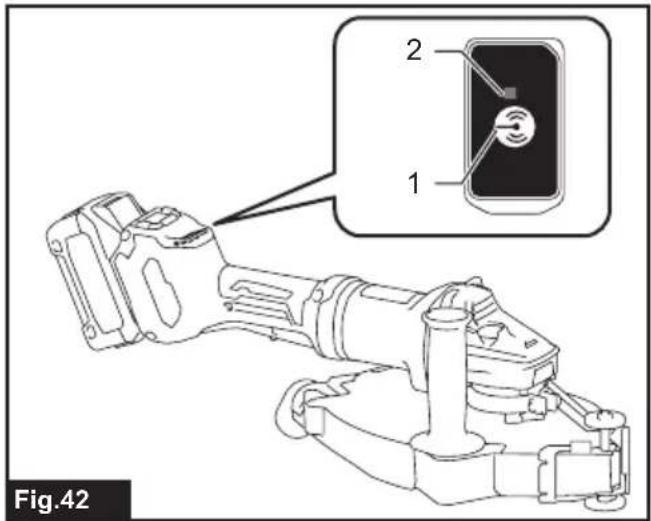
Fig.41: 1. Stand-by switch - Push the wireless activation button on the tool briefly. The wireless activation lamp will blink in blue.
Fig.42: 1. Wireless activation button 2. Wireless activation lamp - Turn on the tool. Check if the vacuum cleaner runs while the tool is operating.
To stop the wireless activation of the vacuum cleaner, push the wireless activation button on the tool.
NOTE: The wireless activation lamp on the tool will stop blinking in blue when there is no operation for 2 hours. In this case, set the stand-by switch on the vacuum cleaner to "AUTO" and push the wireless activation button on the tool again.
NOTE: The vacuum cleaner starts/stops with a delay. There is a time lag when the vacuum cleaner detects a switch operation of the tool.
NOTE: The transmission distance of the wireless unit may vary depending on the location and surrounding circumstances.
NOTE: When two or more tools are registered to one vacuum cleaner, the vacuum cleaner may start running even if you do not turn on your tool because another user is using the wireless activation function.
Description of the wireless activation lamp status
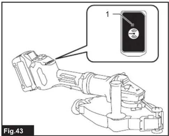
Fig.43: 1. Wireless activation lamp
The wireless activation lamp shows the status of the wireless activation function. Refer to the table below for the meaning of the lamp status.
| Status Wireless activation lamp Description | ||||
| Color | On | Blinking | Duration | |
| Standby Blue | ☐ | 2 hours The wireless activation of the vacuum cleaner is available. The lamp will automatically turn off when no operation is performed for 2 hours. | ||
| ☐ | When the tool is running. The wireless activation of the vacuum cleaner is available and the tool is running. | |||
| Tool registration | Green | ☐ | 20 seconds Ready for the tool registration. Waiting for the registration by the vacuum cleaner. | |
| ☐ | 2 seconds The tool registration has been finished. The wireless activation lamp will start blinking in blue. | |||
| Cancelling tool registration | Red | ☐ | 20 seconds Ready for the cancellation of the tool registration. Waiting for the cancellation by the vacuum cleaner. | |
| ☐ | 2 seconds The cancellation of the tool registration has been finished. The wireless activation lamp will start blinking in blue. | |||
| Others Red | ☐ | 3 seconds The power is supplied to the wireless unit and the wireless activation function is starting up. | ||
| Off | - | - The wireless activation of the vacuum cleaner is stopped. | ||
Cancelling tool registration for the vacuum cleaner
Perform the following procedure when cancelling the tool registration for the vacuum cleaner.
- Install the batteries to the vacuum cleaner and the tool.
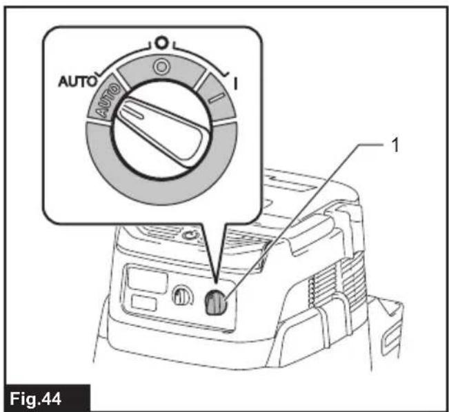
- Set the stand-by switch on the vacuum cleaner to "AUTO".
Fig.44: 1. Stand-by switch
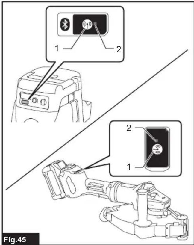
- Press the wireless activation button on the vacuum cleaner for 6 seconds. The wireless activation lamp blinks in green and then become red. After that, press the wireless activation button on the tool in the same way.
Fig.45: 1. Wireless activation button 2. Wireless activation lamp
If the cancellation is performed successfully, the wireless activation lamps will light up in red for 2 seconds and start blinking in blue.
NOTE: The wireless activation lamps finish blinking in red after 20 seconds elapsed. Press the wireless activation button on the tool while the wireless activation lamp on the cleaner is blinking. If the wireless activation lamp does not blink in red, push the wireless activation button briefly and hold it down again.
Troubleshooting for wireless activation function
Before asking for repairs, conduct your own inspection first. If you find a problem that is not explained in the manual, do not attempt to dismantle the tool. Instead, ask Makita Authorized Service Centers, always using Makita replacement parts for repairs.
| State of abnormality Probable cause | (malfunction) Remedy | |
| The wireless activation lamp does not light/blink. | The wireless unit is not installed into the tool.The wireless unit is improperly installed into the tool. | Install the wireless unit correctly. |
| The terminal of the wireless unit and/or the slot is dirty. | Gently wipe off dust and dirt on the terminal of the wireless unit and clean the slot. | |
| The wireless activation button on the tool has not been pushed. | Push the wireless activation button on the tool briefly. | |
| The stand-by switch on the vacuum cleaner is not set to "AUTO". | Set the stand-by switch on the vacuum cleaner to "AUTO". | |
| No power supply | Supply the power to the tool and the vacuum cleaner. | |
| Cannot finish tool registration / cancellation tool registration successfully. | The wireless unit is not installed into the tool.The wireless unit is improperly installed into the tool. | Install the wireless unit correctly. |
| The terminal of the wireless unit and/or the slot is dirty. | Gently wipe off dust and dirt on the terminal of the wireless unit and clean the slot. | |
| The stand-by switch on the vacuum cleaner is not set to "AUTO". | Set the stand-by switch on the vacuum cleaner to "AUTO". | |
| No power supply | Supply the power to the tool and the vacuum cleaner. | |
| Incorrect operation | Push the wireless activation button briefly and perform the tool registration/cancellation procedures again. | |
| The tool and vacuum cleaner are away from each other (out of the transmission range). | Get the tool and vacuum cleaner closer to each other. The maximum transmission distance is approximately 10 m however it may vary according to the circumstances. | |
| Before finishing the tool registration/cancellation; - the switch of the tool is turned on or; - the power button on the vacuum cleaner is turned on. | Push the wireless activation button briefly and perform the tool registration/cancellation procedures again. | |
| The tool registration procedures for the tool or vacuum cleaner have not finished. | Perform the tool registration procedures for both the tool and the vacuum cleaner at the same timing. | |
| Radio disturbance by other appliances which generate high-intensity radio waves. | Keep the tool and vacuum cleaner away from the appliances such as Wi-Fi devices and microwave ovens. | |
| The vacuum cleaner does not run along with the switch operation of the tool. | The wireless unit is not installed into the tool.The wireless unit is improperly installed into the tool. | Install the wireless unit correctly. |
| The terminal of the wireless unit and/or the slot is dirty. | Gently wipe off dust and dirt on the terminal of the wireless unit and clean the slot. | |
| The wireless activation button on the tool has not been pushed. | Push the wireless activation button briefly and make sure that the wireless activation lamp is blinking in blue. | |
| The stand-by switch on the vacuum cleaner is not set to "AUTO". | Set the stand-by switch on the vacuum cleaner to "AUTO". | |
| More than 10 tools are registered to the vacuum cleaner. | Perform the tool registration again. If more than 10 tools are registered to the vacuum cleaner, the tool registered earliest will be cancelled automatically. | |
| The vacuum cleaner erased all tool registrations. | Perform the tool registration again. | |
| No power supply | Supply the power to the tool and the vacuum cleaner. | |
| The tool and vacuum cleaner are away from each other (out of the transmission range). | Get the tool and vacuum cleaner closer each other. The maximum transmission distance is approximately 10 m however it may vary according to the circumstances. | |
| Radio disturbance by other appliances which generate high-intensity radio waves. | Keep the tool and vacuum cleaner away from the appliances such as Wi-Fi devices and microwave ovens. | |
| The vacuum cleaner runs while the tool is not operating. | Other users are using the wireless activation of the vacuum cleaner with their tools. | Turn off the wireless activation button of the other tools or cancel the tool registration of the other tools. |
MAINTENANCE
CAUTION: Always be sure that the tool is switched off and the battery cartridge is removed before attempting to perform inspection or maintenance.
NOTICE: Never use gasoline, benzine, thinner, alcohol or the like. Discoloration, deformation or cracks may result.
To maintain product SAFETY and RELIABILITY, repairs, any other maintenance or adjustment should be performed by Makita Authorized or Factory Service Centers, always using Makita replacement parts.
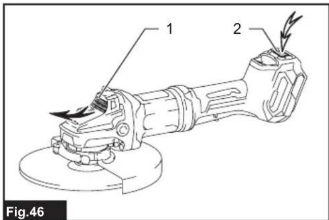
Air vent cleaning
The tool and its air vents have to be kept clean.
Regularly clean the tool's air vents or whenever the vents start to become obstructed.
Fig.46: 1.Exhaust vent 2.Inhalation vent
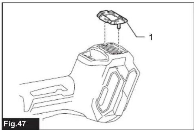
Remove the dust cover from inhalation vent and clean it for smooth air circulation.
Fig.47: 1. Dust cover
NOTICE: Clean out the dust cover when it is clogged with dust or foreign matters. Continuing operation with a clogged dust cover may damage the tool.
COMBINATION OF APPLICATIONS AND ACCESSORIES
Optional accessory
CAUTION: Using the tool with incorrect guards can cause risks as follows.
- When using a cut-off wheel guard for facial grinding, the wheel guard may interfere with the workpiece causing poor control.
- When using a grinding wheel guard for cutting-off operations with bonded abrasive wheels and diamond wheels, there is an increased risk of exposure to rotating wheels, emitted sparks and particles, as well as exposure to wheel fragments in the event of wheel burst.
- When using a cut-off wheel guard or grinding wheel guard for facial operations with cup-type diamond wheels, the wheel guard may interfere with the workpiece causing poor control.
- When using a cut-off wheel guard or grinding wheel guard with a wheel-type wire brush with a thickness greater than the maximum thickness as specified in "SPECIFICATIONS", the wires may catch on the guard leading to breaking of wires.
Use of dust collecting wheel guards for cutting-off and facial operations in concrete or masonry reduces a risk of exposure to dust. - When using dual purpose (combined grinding and cutting-off abrasive) flange mounted wheels, only use a cut-off wheel guard.
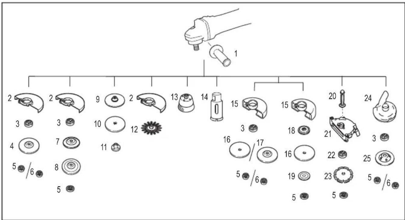
| - Application 180 mm model 230 mm model | ||
| 1 - Side grip | ||
| 2 - Wheel guard (for grinding wheel) | ||
| 3 - Inner flange | ||
| 4 Grinding / Sanding Depressed center wheel / Flap disc | ||
| 5 - Lock nut | ||
| 6 - Ezynut *1 | ||
| 7 - | Back up pad | |
| 8 | Grinding | Flex wheel |
| 9 - Rubber pad | ||
| 10 | Sanding | Abrasive disc |
| 11 | - | Sanding lock nut |
| 12 | Wire brushing | Wire wheel brush |
| 13 | Wire brushing | Wire cup brush |
| - Application 180 | mm model 230 mm model | ||
| 14 Hole cutting Hole cutter | |||
| 15 - Wheel guard (for cut-off wheel) | |||
| 16 Cutting-off Abrasive cut-off wheel / Diamond wheel | |||
| 17 | Grinding / Cutting-off | Dual purpose wheel | - |
| 18 - Inner flange 78 (Australia and New Zealand only) *2 | |||
| 19 - Outer flange 78 (Australia and New Zealand only) *2 | |||
| 20 - Side grip for dust collecting wheel guard *3 | |||
| 21 | - | Dust collecting wheel guard for cutting-off *3*4 | |
| 22 - | Special flange *5 | ||
| 23 | Cutting-off | Diamond wheel | |
| 24 | - | Dust collecting wheel guard for grinding *6 | |
| 25 | Grinding | Cup-type diamond wheel *6 | |
| - | - | Lock nut wrench | |
NOTE: 1 Only for tools with M14 spindle thread.
NOTE: 2 Use Inner flange 78 and Outer flange 78 together. (Australia and New Zealand only)
NOTE: 3 Use the Side grip for dust collecting wheel guard and the Dust collecting wheel guard for cutting-off together.
NOTE: 4 For more details, refer to each instruction manual of the guard.
NOTE: 5 The Inner flange for the grinder equipped with the brake function when using together with the dust collecting wheel guard.
NOTE: 6 For more details, refer to each instruction manual of the guard.
OPTIONAL ACCESSORIES
CAUTION: These accessories or attachments are recommended for use with your Makita tool specified in this manual. The use of any other accessories or attachments might present a risk of injury to persons. Only use accessory or attachment for its stated purpose.
If you need any assistance for more details regarding these accessories, ask your local Makita Service Center.
- Makita genuine battery and charger
- Accessories listed in "COMBINATION OF APPLICATIONS AND ACCESSORIES"
- Wireless unit (For models with wireless activation function)
NOTE: Some items in the list may be included in the tool package as standard accessories. They may differ from country to country.
SPECIFICATIONS
Fig.17: 1. Flèche 2. Encoche
Fig.18
ACCESSIONS EN OPTION
VEILIGHEIDSWAARSCHUWINGEN
OPTIONELE ACCESSOIRES
Fig.17: 1. Pil 2. Hak
Fig.18
Móvo yia xwpe ts Eupwnns


- GA037G GA038G
- Applicable battery cartridge and charger
- Recommended cord connected power source
- Symbols
- Intended use
- Noise
- Vibration
- EC Declaration of Conformity
- For European countries only
- SAFETYWARNINGS
- General power tool safety warnings
- Save all warnings and instructions for future reference.
- Cordless grinder safety warnings
- Kickback and related warnings:
- Safety warnings specific for grinding and cutting-off operations:
- Additional safety warnings specific for cutting-off operations:
- Safety warnings specific for sanding operations:
- Safety warnings specific for wire brushing operations:
- Additional SafetyWarnings:
- SAVE THESE INSTRUCTIONS.
- Important safety instructions for battery cartridge
- Tips for maintaining maximum battery life
- Important safety instructions for wireless unit
- FUNCTIONAL DESCRIPTION
- Installing or removing battery cartridge
- Indicating the remaining battery capacity
- Tool / battery protection system
- Overload protection
- Overheat protection
- Overdischarge protection
- Protections against other causes
- Shaft lock
- Switch action
- Accidental re-start preventive function
- Active Feedback sensing Technology
- Soft start feature
- Electric brake
- ASSEMBLY
- Installing side grip (handle)
- For tool with locking screw type wheel guard
- For tool with clamp lever type wheel guard
- Installing or removing depressed center wheel or flap disc
- Optional accessory
- Installing or removing flex wheel
- Installing or removing abrasive disc
- Installing or removing Ezynut
- Only for tools with M14 spindle thread.
- Installing abrasive cut-off / diamond wheel
- For Australia and New Zealand
- Installing wire cup brush
- Installing wire wheel brush
- Installing hole cutter
- Installing dust collecting wheel guard for grinding
- Installing dust collecting wheel guard for cutting-off
- Connecting a vacuum cleaner
- OPERATION
- Grinding and sanding operation
- Fig.27
- Operation with abrasive cut-off / diamond wheel
- Operation with wire cup brush
- Operation with wire wheel brush
- Operation with hole cutter
- WIRELESS ACTIVATION FUNCTION
- What you can do with the wireless activation function
- Installing the wireless unit
- Tool registration for the vacuum cleaner
- Starting the wireless activation function
- Description of the wireless activation lamp status
- Fig.43: 1. Wireless activation lamp
- Cancelling tool registration for the vacuum cleaner
- Troubleshooting for wireless activation function
- MAINTENANCE
- Air vent cleaning
- COMBINATION OF APPLICATIONS AND ACCESSORIES
- OPTIONAL ACCESSORIES
- ACCESSIONS EN OPTION
- VEILIGHEIDSWAARSCHUWINGEN
- OPTIONELE ACCESSOIRES
Brand : MAKITA
Model : GA038G
Category : Garden shredder