
Xenyx UFX1604 - Hand blender BEHRINGER - Free user manual and instructions
Find the device manual for free Xenyx UFX1604 BEHRINGER in PDF.
| Product type | 16-channel digital/analog mixing console |
| Brand | Behringer |
| Model | Xenyx UFX1604 |
| Number of channels | 16 (8 mono + 4 stereo) |
| Microphone inputs | 8 with Xenyx preamps, 48V phantom power |
| Line inputs | 16 (8 mono + 4 stereo) on 6.35mm jacks |
| Main outputs | 2 x balanced XLR, 2 x 6.35mm jacks |
| Auxiliary buses | 4 (AUX SEND 1-4) |
| Effects processors | 2 built-in multi-effects (FX A and FX B) |
| Equalization | 4-band (HIGH, HIGH MID, LOW MID, LOW) per channel |
| Digital connectivity | FireWire (IEEE 1394) and USB 2.0 |
| Recording | 16 tracks to computer (FireWire/USB) or to USB drive in standalone mode |
| Power supply | 100-240 V AC, 50/60 Hz (external power adapter) |
| Dimensions (W x D x H) | Approximately 440 x 400 x 110 mm |
| Weight | Approximately 7.2 kg |
| Maintenance and cleaning | Use a dry, soft cloth; do not use solvents or abrasive products |
| Safety | Do not open the device; unplug before cleaning; use professional cables |
| Spare parts and repairability | Repair only by qualified technician; no user-serviceable parts |
| General information | Versatile mixing console for studio and stage; limited warranty (see Behringer website) |
Frequently Asked Questions - Xenyx UFX1604 BEHRINGER
User questions about Xenyx UFX1604 BEHRINGER
0 question about this device. Answer the ones you know or ask your own.
Ask a new question about this device
Download the instructions for your Hand blender in PDF format for free! Find your manual Xenyx UFX1604 - BEHRINGER and take your electronic device back in hand. On this page are published all the documents necessary for the use of your device. Xenyx UFX1604 by BEHRINGER.
USER MANUAL Xenyx UFX1604 BEHRINGER
natural_image
Black-and-white collage of three music events: a singer with headphones, a CD studio with audience and stage lights, and a man smiling at the desk (no visible text or symbols)XENYX UFX1604
Premium 16-Input 4-Bus Mixer with 16 x 4 USB/FireWire Interface, 16-Track USB Recorder, XENYX Mic Preamps & Compressors, British EQs and Dual Multi-FX Processors
2 XLNYX U-X160V Quick Start Guide 3
EN
ES

Terminals marked with this symbol carry electrical current of sufficient magnitude to constitute risk of electric shock. The only high quality professional speaker cables with 16" TS or twist locking plugs pre installed. All other installation or modification should be performed only by qualified personnel.
This symbol, wherever it appears, alerts you to the presence of uninsulated dangerous voltage inside the enclosure—voltage that may be sufficient to constitute a risk of shock.
This symbol, wherever it appears, alerts you to important operating and maintenance instructions in the accompanying literature. Please read the manual.
Caution To reduce the risk of electric shock, do not remove the top cover (or the rear section). No user serviceable parts inside. Refer servicing to qualified personnel
Caution To reduce the risk of fire or electric shock, do not expose this appliance to rain and moisture. The apparatus shall not be exposed to dripping or splashing liquids and no objects filled with liquids, such as wares, shall be placed on the apparatus.
Caution These service instructions are for use by qualified service personnel only. To reduce the risk of electric shock do not perform any servicing other than that contained in the operation instructions. Repairs have to be performed by qualified service personnel.
- Read these instructions.
- Keep these instructions.
- Need all warnings.
- Follow all instructions.
- Do not use this apparatus near water.
- Clean-only with dry cloth.
- Do not block any ventilation openings. Install in accordance with the manufacturer's instructions.
-
Do not install near any heat sources such as radiators, heat registers, stoves, other apparatus (including amplifier) that produce heat.
-
Do not defeat the safety purpose of the polarized or grounding-type plug. A polarized plug has two blades with one wider than the other. A grounding-type plug has two blades and a third grounding proing. The wide blade or the third proing are provided for your safety. If the provided plug does not fit into your outlet, consult an electrician for replacement of the obsolete outlet.
-
Protect the power card from being walked on or pinched particularly at plugs, convenience receptacles, and the point where they exit from the apparatus.
- Use only attachments/accessories specified by the manufacturer.

- Use only with the cart, stand, tripod, bracket, or table specified by the manufacturer, or sold with the apparatus. When a cart is used, use caution when moving the cart/apparatus combination to avoid
injury from tip over
-
Unplug this apparatus during lightning storms or when unused for long periods of time.
-
Refer all servicing to qualified service personnel. Servicing is required when the apparatus has been damaged in any way, such as power supply cord or plug is damaged, liquid has been spilled or objects have fallen into the apparatus, the apparatus has been exposed to rain or moisture, does not operate normally, or has been dropped.
-
The apparatus shall be connected to a MURS socket outlet with a protective earthing connection.
-
Where the MAINS plug or an appliance coupler is used as the disconnect device, the disconnect device shall remain nearly operable.

- Correct disposal of this product: This symbol indicates that this product must not be disposed of with household waste, according to the IEEE Directive (2012/19/10) and your national law. This product should be taken
In a collection center licensed for the recycling or waste electrical and electronic equipment (EEC). The misunderstanding of the type of waste could have a possible negative impact on the environment and human health due to potentially hazardous substances that are generally associated with EEC. At the same time, your cooperation is in the correct disposal of this product will contribute to the efficient use of natural resources. For more information about where you can take your waste equipment for recycling, please contact your local city office, or your household waste collection service. 18. Do not install in a confined space, such as a stock case or similar unit.
-
Do not place naked flame sources, such as lighted candles, on the apparatus.
-
Please keep the environmental aspects of battery disposal in mind. Batteries must be disposed-of at a battery collection point.
- Use the apparatus in tropical and/or moderate climates.
LEGAL DISCLAIMER
MUSIC Group accepts no liability for any loss which may be suffered by any person who relies either wholly or in part upon any description, photograph, or statements contained herein. Technical specific claims, appearances and other information are subject to change without notice. All trademarks are the property of their respective owners. MIDAS, KLARK TERNIK, LAB GRUPPEN, LAKE, TANNKY, TURBOSOUNO, TC ELECTRONIC, TC HELICON, BENJINGER, BUGERA and DOA are trademarks or registered trademarks of MUSIC Group IP Ltd. 92 MUSIC Group IP Ltd. 2017 All rights reserved.
LIMITED WARRANTY
For the applicable warranty terms and conditions and additional information regarding MUSIC Group's Limited Warranty, please see complete details online at music-group.com/warranty.
ES
BESCHRÄNKTE GARANTIE
XENYX UFX1604 Hook-up
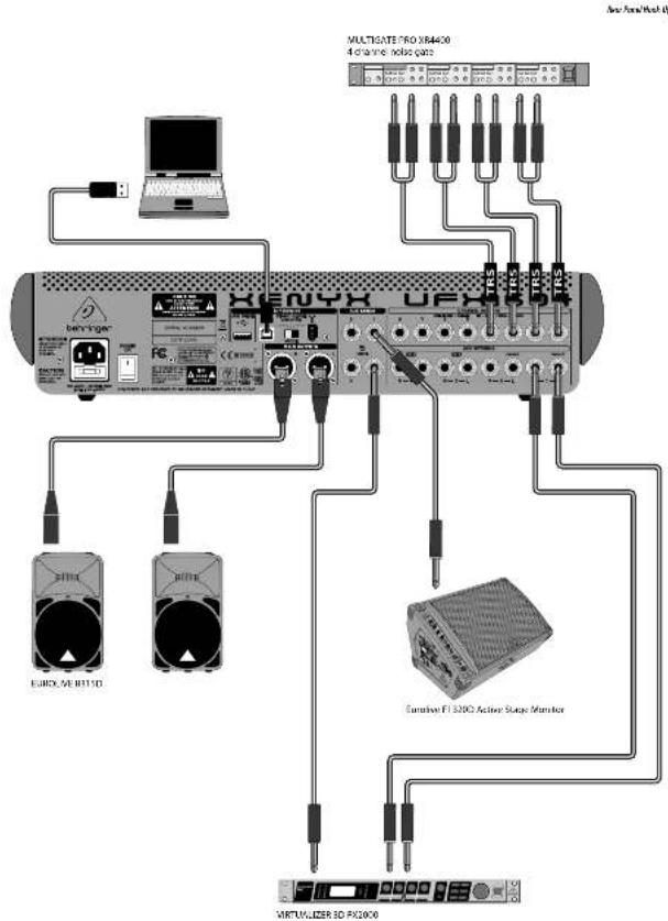
Step 1: Hook-Up
ES Paso 1: Conexión
Etape 1 : Connexions
DF Schritt 1: Verkabelung
PT Passo 1: Conexões
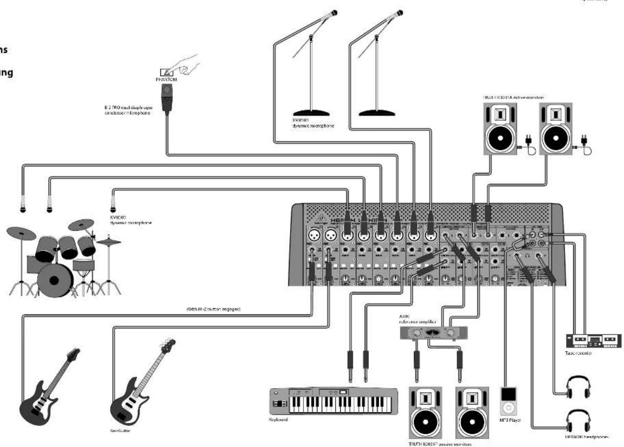
flowchart
graph TD
    A["Phantom"] --> B["8.2 THO audio microphone condenser microphone"]
    C["XV4000 dynamic microphone"] --> D["100000+ HEBM-1.1"]
    E["Handheld"] --> F["Radio buttons"]
    G["Spectris"] --> H["Radio buttons"]
    I["Handheld"] --> J["Radio buttons"]
    K["Handheld"] --> L["Radio buttons"]
    M["Handheld"] --> N["Radio buttons"]
    O["Handheld"] --> P["Radio buttons"]
    Q["Handheld"] --> R["Radio buttons"]
    S["Handheld"] --> T["Radio buttons"]
    U["Handheld"] --> V["Radio buttons"]
    W["Handheld"] --> X["Radio buttons"]
    Y["Handheld"] --> Z["Radio buttons"]
    AA["Handheld"] --> AB["Radio buttons"]
    AC["Handheld"] --> AD["Radio buttons"]
    AE["Handheld"] --> AF["Radio buttons"]
    AG["Handheld"] --> AH["Radio buttons"]
    AI["Handheld"] --> AJ["Radio buttons"]
    AK["Handheld"] --> AL["Radio buttons"]
    AM["Handheld"] --> AN["Radio buttons"]
    AO["Handheld"] --> AP["Radio buttons"]
    AQ["Handheld"] --> AR["Radio buttons"]
    AS["Handheld"] --> AT["Radio buttons"]
    AU["Handheld"] --> AV["Radio buttons"]
10 11 Quick Start Guide XLNYX.UI-X 60M
XENYX UFX1604 Hook-up
Step 1: Hook-Up
ES Paso 1: Conexión
Etape 1: Connexions
Schritt 1: Verkabelung
PT Passo 1: Conexões
12 13 Quick Start Guide LNYX U-X160
XENYX UFX1604 Controls
XENYX UFX1604 Controls
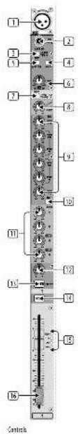
Step 2: Controls
(1) XLR balanced input.
② LINE#HI-Z input.
LINE/HI-Z button. When HI-Z mode is engaged, you can plug your guitar or bass into this input without using an external direct input (D.I.) box.
4 +48 V Phantom power is used for condenser microphones that require between 9 V DC and 48 V DC power to operate.
[5] LOW CUT button filters out frequencies below 80 Hz.
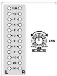
GAIN knob adjusts the sensitivity of the MIC and LIKE/HI-Z inputs.
☐ SEND lets you choose to route your input signal to FireWire?USB pre or post CO.
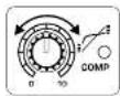
COMPRESSOR knob adjusts the amount of compression effect on the channel.
EQ knobs adjust the HIGH, HIGH MID, LOW MID, and LOW frequencies of the channel.
EQ button turns the EQ section on and off.
11 AUX / FX A and FX B knobs adjust how much of the channel's signal is sent to the AUX SEND jacks and/or the internal FX processors.
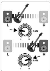
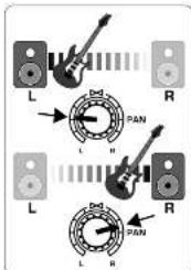
12 PAN knob positions the channel's signal in the stereo field.
12 MUTE button removes the channel from the MAIN MID and sends it to the ALT 3-4 bus.
15 SOLO button sends the channel signal to the solo bus (Solo in Place) or to the PFL bus (Pre-Fader Listen).
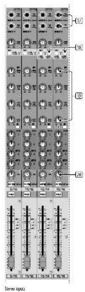
(15) LEVEL METER shows the input signal level of the channel's input signal.
(16) CHANNEL FADER adjusts the channel volume.
⑰ LINE IN left and right input jacks for mono or stereo signals.
(18) LINE/TW 1-2 (3-4) button allows the signal from a computer to be routed via FireWire/USB to these channels and controlled by the EQ and AUX and Fader functions.
NOTE: All FireWire (TW) routing switches work for USB connectivity to a computer and for the USB stand-alone mode depending on how you have the MODE selector switch (50) set.
(16) 4-band EQ for the stereo channels.
20 BAL(ANCE) knob controls the relative volume of the left and right input signals before they are routed to the stereo main mix bus.
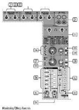
21 CONTROL ROOM OUT jacks carry the summed effects and main mix signals, as well as solced channel signals.
(22) MAIN OUT jacks for connecting line level signal to powered speakers or external amplifier.
(25) ALT 3-4 OUT lacks for connecting line level signal of an alternate stereo mix to a recording device, powered speakers or external amplifier. Can also be used for subgrouping.
(24) CDyTAPE IN and OUT for connecting a stereo source or for sending the main signal to an external recorder.
23 PHONES jacks for connecting headphones.
[26] INPUT level meters display the signal input intensity going into the FX A or FX B bus.
31 FX A effect knob selects which effect is applied to the signal (same for FX B).
23 EDIT knob adjusts the effect's main parameter.
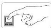
(29) FX ON button turns the effect on and off.
(36) The TAP/SELECT button performs two functions. Hit the button several times in the tempo of the music piece to adapt the delay time of presets 9 and 15 or the modulation speed of presets 10-12. The button will start flashing in the corresponding tempo. The TAP/SELECT button also changes the characteristic of the second parameter on presets 1-8, 13-14 and 16. By pressing the button you can toggle between two different values (light off/on) for the second parameter.
(31) FIN/USB LED indicates the computer is connected (based on the selection switch on back panel).
(32) VU METER displays the MAIN OUTPUT signal level.
MODE button determines whether the SOLO button operates in 'Solo In Place' (button out) or 'Pre-Fader Listen' (button in). PFL is preferred for gain setting purposes.
☐ PHONES knob controls the volume level of the PHONES jacks.
35 CONTROL RM knob controls the volume of the CONTROL ROOM OUT jacks.
(36) SOURCE monitoring select buttons route the signal to either the CONTROL RV/PHONES jacks (left column) or the MAIN MIX (right column).
(37) PRE/POST fader select buttons for all 4 AUX SEND busses.
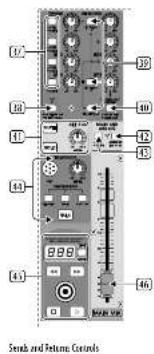
(8) AUX SEND 1-2 to PN 13-14 switch disables mixer channels 13-14 from being sent via FireWire/USB so that AUX SEND 1-2 can be routed to a computer (for recording, etc.).
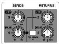
(39) Destination routing switches for AUX RETURN 3 source signal.
42 Destination routing switch for AUX RETURN 4 (to MAIN bus or CONTROL ROOM/PHONES bus).
(41) MUTE, SOLO and output LEVEL knobs for ALT 3-4 bus.
(42) Assign to FW 15-16 switch sends the MAIN MIX signal via FireWire/USB to computer or external USB drive when in the ON position. When off, mixer channels 15-16 can be sent via FireWire/USB.
41 PRE/POST switch sends the MAIN MID signal to Fire/Wire/USB pre or post main fader (requires ASSIGN TO FW 15-16 switch to be on).
51 TALKBACK MIC (built-in), LEVEL knob (adjusts TALKBACK microphone volume), DESTINATION switches and TALK button (press while talking).
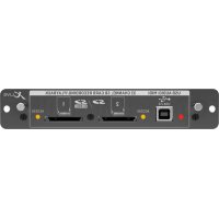
16 TRACK USB DRIVE RECORDER/MIDI TRANSPORT CONTROL for use while connected to a computer via FireWire or USB as a MIDI Machine Control. Also used In STAND ALONE MODE for controlling the internal USB recorder functions.
[46] MAIN MIX stereo fader adjusts the overall output of the mixer.
[47] POWER ON turns the mixer on.
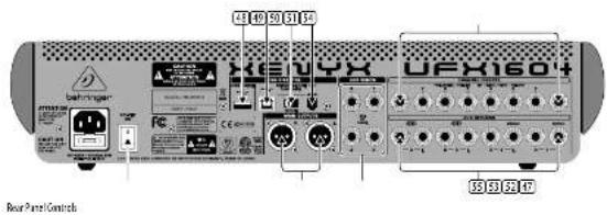
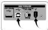
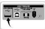
[48] USB DRIVE jack for use with external USB hard disk drives (recommended) or thumb drives in STAND ALONE mode.
49 USB jack for connecting to a computer.
MODE selector switch.
51 FireWire jack for connecting to a computer.
52 MAIN OUTPUTS for sending MAIN MIX via balanced XLR cables.
53 AUX(ILIARY) SENDS route the 4 auxiliary bus signals via balanced or unbalanced N* cables.
54 CHANNEL INSERTS allow you to connect external effects to the individual channels (1-8) PRE-FADER and PRE-EQ.
15. AUX(LIARY) RETURNS allow you to bring a store effects signal routed from an AUX SEND jack, through a processor, back into the designated auxiliary bus. These inputs can also be used to connect additional line sources such as keyboards.
XENYX UFX1604 Controles
FS Paso 2: Controles
XENYX UFX1604 Controles
PT Passo 2: Controles
XENYX UFX1604 Getting started
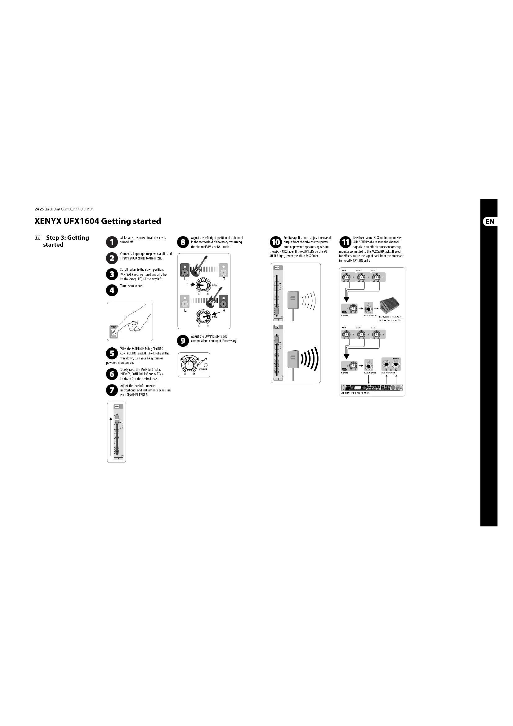
Step 3: Getting started
1 Make sure the power to all devices is turned off.
2 Connect all appropriate power, audio and Fire/Wire/USB cables to the mixer.
3 Set all faders to the down position, PAN/BAL knobs centered and all other knobs (except EO) all the way left.
4 Turn the miner on.
5 With the MAIN MIX fader, PHONES. CONTROL RX, and ALT 3-4 knobs all the way down, turn your PV system or powered monitors on.
6 Slowly raise the MAIN MIX fader, PHONES, CONTROL RM and ALT 3.4 knobs to 0 or the desired level.
7 Adjust the level of connected microphones and instruments by raising each CHANNEL FADER.
8 Adjust the left-right position of a channel in the stereo field if necessary by turning the channel's PAN or BAL knob.
9 Adjust the COMP knob to add compression to an input if necessary.
10 For live applications, adjust the overall output from the mixer to the power amp or powered speakers by raising the MAIN MIX fader. If the CLIP LEDs on the VII METER light, lower the MAIN MIX fader.
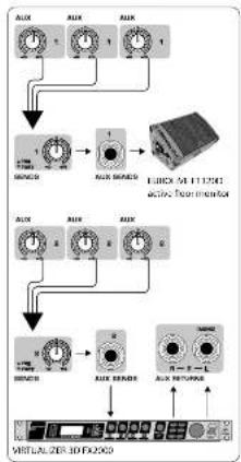
11 Use the channel AUX knobs and master AUX SEND knobs to send the channel signals to an effects processor or stage monitor connected to the AUX SEND jacks. If used for effects, route the signal back from the processor to the AUX RETURN jacks.
flowchart
graph TD
    A["Input Condition 1"] --> B{Signal Input}
    B --> C["Adder"]
    C --> D["Output"]
    D --> E["Virtualizer Interface"]
    E --> F["Output"]
    F --> G["Feedback to Input"]
    G --> H["Output"]
26 27 Quick Start QuickEx_NFX DJX1601
Gain Setting Dual Multi-FX Processors
Step 4: Gain Setting
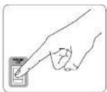
1 Press the Channel 1 SOLD button. Press the MODE button under the VU METER in the main section to allow the VETER to operate in PTL (pre-fader listen) mode.
2 Sing, Speak or play at a normal level through the microphone or instrument connected to Channel 1.

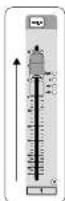
While singing or playing, turn Channel 1'S GAIN knob. The VU METER will display the signal level. Set the GAIN so the loudest peaks reach 0 on the VU METER. Press the Channel 1 SOLO button again.
4 Repeat steps 1-3 for any other channels that will be used.
Step 5: Dual Multi-FX Processors
Your mixer has two built-in effects processors. Follow these steps to add one or two effects to one or more channels.
1 Turn the FX A or FX B knob up halfway on each channel you would like to add an effect to.
2 Turn the FX SEND and FX RETURN knobs to "0". You may adjust them later.
3 Make sure the FX OK button is pushed in.
4 Scroll through the effects by turning the FX A knob (same for FX B).
5 Adjust the intensity of the effect by turning the EDIT knob.

6 If using presets 1-8, 13-14 or 16, press the TAP/SELECT button to toggle between two different values (light off/on) for the second parameter.
To adjust the delay time of presets 9 and 15, hit the TAP/SELECT button several times in the tempo of the music piece. Similarly, hit the TAP/SELECT button several times to adjust the modulation speed of presets 10-12. The button will start flashing in the corresponding tempo.
7 Readjust each channel's FX knots to make sure the right amount of FX A or FX B is added.
28 29 Quick Star GuideXLNYX LI X16CM
FireWire and USB recording Recording to USB drive in STAND-ALONE mode
Step 6: FireWire and USB recording
Your mixer is equipped with AD/DA converters, FireWire and USB connections for sending audio to and from your computer.

Make sure the drivers for the UFX1604 are loaded on your Windows computer (driver is not required for Mac OS X).

Connect the mixer to the computer via FireWire or USB. Make sure you set the 3-way switch on the back panel of the rounding.

Select the UFX7604 inputs and outputs you'd like to use in your recording software.

Set your desired sample rate and bit depth from within your DAW (digital audio workstation) software.

Connect your microphones, instruments and line level sources to the channel inputs. Each channel can be recorded pre as its own mono or stereo track in your software. It is also possible to record the on channels 13/14.
The MAIN MIX can also be recorded by pressing the MAIN MIX ASSIGN TO FIN 15-16 button. This will send the main mix to your DAW through output 15/16.

Arm the tracks in your recording software and record when ready.
Step 7: Recording to USB drive in STAND-ALONE mode

Make sure the STAND ALONE mode is selected on the back of the mixer (center position).

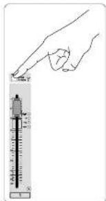
When a new USB drive is inserted for the first time, the mixer tests the writing speed of the drive to determine quality. The outcome appears on the T CONTROL screen as "Lo" [16 bit] or "Hi" he drive is too slow for recording, will show "SLO" after testing.

If your drive needs to be formatted, press □ and □ simultaneously on the TRANSPORT CONTROL until the ds, "For" (blinking). Push □ to initiate or □ to abort.

To show the sample rate setting, push and hold the TIME REMAIN button until the sample rate is displayed.

To change the sample rate to 44.1 kHz, push and hold TIME REMAIN until the sample rate appears and then
press

To change the sample rate to 48 kHz, push TIME REMAIN until the sample rate appears and then press ☐ while g TIME REMAIN.

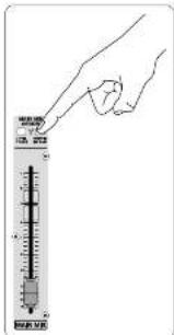
With all your microphones, instruments and source signals connected press the 📄 button on the CONTROL to create a new folder on the with the individual channels as files. Options! You are now recording.

Press ☐ when finished. The recordings are displayed on the TRANSPORT CONTROL screen as (-99).

To toggle between recording and playlist modes, press TIME REMAIN and 📄 at the same time for
two seconds.

To listen or navigate through recordings you have made, you must be in recording mode. Playlist mode is ONLY back WAV files you copied to your drive Mac.
for playing back WAV files you copied to your drive from a PC/Mac.
While in recording mode, press ▼ to hear what you just recorded. To return to the start, press the ▼ button on the TRANSPORT CONTROL once. Press ▼ twice to move to the previous recording. Press ▼ to move to the start of the next recording. Note: long push on the ▼ or ▼ will not fast forward or rewind within the track. ONLY tracks 15 and 16 will be played back on channels 15 and 16 unless you route the MAIN MIX signal to FW 15-16 (in the MAIN MIX ASSIGN section). This allows the MAIN MIX signal to be recorded and played back via channels 15 and 16.

To toggle between single playback and continuous playback mode (in playlist mode), long press PLAY.

To delete the current song in recording mode, playback or recording must be stopped. Press ▶ and ▶ together. to complete deletion or ▶ to cancel.

IMPORTANT NOTE: the USB recorder only plays songs if they are .wav files with sample rates of 44.1 or 48.0 kHz older labeled "MyNav." No subfolders
30 31 Quick Start GuideXENYX UI X '62M
Recording to USB drive in STAND-ALONE mode
Step 7: Recording to USB drive in STAND-ALONE mode
| Transport Control Feature Chart | |
| Show Remeshring Time | Press TIME REMAIN short |
| Show Sampling Rate | Push and hold TIME REMAIN button until the sample rate is displayed |
| Select Sampling Rate 44.1 kHz | Push and hold TIME REMAIN until the sample rate appears and then press != while still holding TIME REMAIN |
| Select Sampling Rate 48 kHz | Push TIME REMAIN until the sample rate appears and then press != while still holding TIME REMAIN |
| Toggle PLAY <> PAUSE | Press PLAY*to start > press PLAY*to pause> press PLAY (to continue) => etc. |
| Toggle Reverting Mode (e.g. "001") <> Playlist Mode (e.g. "PST") | Push TIME REMAIN + for two seconds |
| Toggle Since Playlock, "Pass") <> Continuous ("cox") Playlist [only in Playlist Mode] | Push PLAY*for two seconds |
| FAT-formulating the USB drive* | Press together STOP = for two seconds |
| Delete current song (in Recording Music)* | Press together PLAY = for two seconds |
*Yes (A) is common for other categories but
| Error Codes: | |
| D-P | Dropout while recording. A summary of the total number of dropouts will be displayed after recording (eg. 2015). |
| FIL | The system error, incompatible file system on the drive. Drive must be formatted by the UPL. |
| cFF | Recorder switches off if a drive has been specified as SLO (on vivo) |
| SLG | The connected USB drive has been specified as bus slow. No recording will be possible. |
• Group, 3016: on 25th-century Western Europe (Western Europe) and the European countries (Western Europe) are part of the European countries.
Using the MIDI CONTROL Features
Step 8: Using the MIDI CONTROL Features
The TRANSPORT CONTROL section on the UFX1604 can operate as a MIDI controller in one of two modes: STANDARD MIDI MODE or MACKIE CONTROL MODE.

The Mixer must be turned off.

To select MACKIE CONTROL MODE, hold ☐, turn the power on and then release ☐ when "MAC" shows up in. To select STANDARD MIDI MODE.
Hold ☐, turn the power on, then release ☐ when "STD" shows up in the display.

For STANDARD MIDI MODE, map the transport controls in your recording software to the TRANSPORT CONTROL the UX1604. In MACKIE CONTROL MODE, ordering software to follow the protocol.
For further information, see the full manual at behringer.com.
32 33 QuickStart GuideXLNYX L1X160Y
Puesta en marcha
"The following text is not possible to be extracted from the source image.
In open interest positions (By theorem 2.1) of the ^3 class of the ^3 class of the ^3 class of the ^3 class of the ^3 class of the ^3 class of the ^3 class of the ^3 class of the ^3 class of the ^3 class of the ^3 classes of the ^3 class of the ^3 class of the ^3 class of the ^3 class of the ^3 class of the ^3 class of the ^3 class of the ^3 class of the ^3 class of the ^3


On the 186-like and non-186 members, a natural factor in each case, can be seen as the number of controls. The number of controls is 22 units of the total level of the control system.
Passo 5: Processadores Dual Multi-FX
| MicroInputs | |
| Microwave inputs (N=40K mic pramp) | B |
| Type | XLR, electronically balanced, discrete input circuit |
| Mic E.L.M. (20 Hz - 20 kHz) | |
| at 0.0 source resistance | -125 dB / 112 dB A-weighted |
| @ 50 C source resistance | -128 dB / 130.5 dB A-weighted |
| at 150 C source resistance | -126 dB / 129 dB A-weighted |
| Frequency response | <10 Hz - 140 kHz / 1dB) <10 Hz - 200 kHz / 3 dB) |
| Gain range | +10 dB to +60 dB |
| Max. input level | +12 dB to +10 dB gain |
| Impedance | impedance 700 dB balanced |
| Signal-to-noise ratio | 112 dB A-weighted ≥ 10 dB in @ -32 dB gain) |
| Distortion (THD-A) | 0.004 dB/(-20 dB in @ -20 dB gain) |
| Phantom power | +45 V, switchable per mic channel |
| H. Z Input Impedance | 1 MHz |
| Line Inputs | |
| Type | 1/2 TBS connector, balanced |
| Impedance | 20 kHz balanced, 10 kHz unbalanced |
| Gain range | -10 dB to -60 dB |
| Max. input level | 30 dBu |
| Stereo Inputs | |
| Type | 1/2 TBS connector, balanced |
| Impedance | 20 kHz balanced, 10 kHz unbalanced |
| Gain range | -20 dB to -20 dB |
| Max. input level | +72 dBu |
| Co Tape In | |
| Type | RCA connector |
| Impedance 10 kHz | |
| Max. input level | +72 dBu |
| EQ Mono Channels | |
| Low | 80 kHz / ±15 dB |
| Low mid | 100 kHz to 2 kHz / -15 dB |
| High mid | 400 kHz to 8 kHz / ±15 dB |
| High | 12 kHz / ±15 dB |
| Low cut | 80 kHz / ±8 dB/act |
| EQ Stereo Channels | |
| Low | 80 kHz / ±15 dB |
| Low mid | 300 kHz / ±35 dB |
| High mid | 3 kHz / ±15 dB |
| High | 12 kHz / ±15 dB |
| Channel Inserts | |
| type | 1/2 TBS connector, unbalanced |
| Max. input level | +22 dBu |
| Crosswalk | |
| Main fader closed | 90 dB |
| Channel mixed | 80 dB |
| Channel fader closed | 80 dB |
| Aux Sends | |
| type | 1/2 TBS connector, unbalanced |
| Impedance 120°C | |
| Max. input level | +72 dBu |
| Max Returns | |
| Type | 37 TRS connector, balanced |
| Impedance | 20 kΩ balanced, 10 kΩ unbalanced |
| Max. input level | +22 dBz |
| Main Outputs | |
| Type | 31 R and % TRS balanced |
| Impedance | 240.0 balanced, 120.0 unbalanced |
| Max. output level | +28 dBz |
| Central Resion Output | |
| Type | 37 TRS connector, unbalanced |
| Impedance 120.0 | |
| Max. output level | +22 dBz |
| Dual Phone Output | |
| Type | 37 TRS connector, unbalanced |
| Max. output level | +22 dBz / 23 I~ 300 mV @ 100 Hz |
| CD/Scape Out | |
| Type | RCA connector |
| Impedance 1 kΩ | |
| Max. output level | +22 dBz |
| Dual Efforts | |
| Convertors | 2 x 24-bit Delta-Sigma, 128-cms oversampling |
| Sampling rate | 48kHz |
| FireWire/USB Interface | |
| Operation modes | FireWire 400 or USB 2.0 |
| Connectors | 6-pin FireWire 400 (IEEE 1294M), USB 2.0 type B |
| Convertors | 26 bit |
| Sample rate | 44.1 kHz, 48 MHz, 88.2 kHz, 96 kHz |
| Channel number | 16 x 16x out |
| Operating systems | Windows XP or higher, Max OS X |
| Low latency audio support | ASIC (W/m), OneAudio (Max) |
| Transport section MIO control | Standard NIOI mode (ICRTC commands) or Mackie control mode |
| USB Recorder (Stand Alone Mode) | |
| Connector | USB 2.0 (Type A) |
| Storage device | External USB 2.0 hard-class drive (expression depends on required power consumption) |
| Sample size | 44.1 kHz, 48 kHz |
| File format | VMAX (uncompressed) |
| File system | FAT 16 / FAT 12 |
| Number of recorded channels | 16 tracks (stored as mono VMAX tiles) |
| Power Supply | |
| Maine ratings | 100 ~ 240 V~, 50/50 Hz |
| Power consumption | 65 W |
| Fuse (100 ~ 250 V~, 50/80 Hz) | 1.2A 1250 V |
| Maine connector | Standard EC receptacle |
| Physical Weight | |
| Dimensions (ft x 10 x 30) | 100 x 445 x 5475 mm(1.1 x 175 x 21.6") |
| Weight | 7.3 kg (16.1 lbst) |
The workplace
| Effect no. | Effect | EUR Parameter 1 | TAP/SELECT Parameter 2 | TAP/SELECT LED |
| 1 | CATHERMAL | Reverse time | Brilliance | offson |
| 2 | CONCERIT | Reverse time | Brilliance | offson |
| 3 | CLUB | Reverse time | Brilliance | offson |
| 4 | OLIMBER | Reverse time | Brilliance | offson |
| 5 | GOLD-PLATE | Reverse time | Brilliance | offson |
| 6 | GARLICRY | Reverse time | Brilliance | offson |
| 7 | REVERSE | Reverse time | Brilliance | offson |
| 8 | AMSHEAT | Room size | Brilliance | offson |
| 9 | BILLY | No. of repetitions | Time interval DAP | flashing (BPS tempo) |
| 10 | OHORUS | Intensity | Tempo TAP | flashing (temps) |
| 11 | FLAGGER | Intensity | Tempo TAP | flashing (temps) |
| 12 | PHASER | Intensity | Tempo TAP | flashing (temps) |
| 13 | BOTARY | Intensity | Tempo | offson |
| 14 | PTCH'S LIFT | Semi time steps (-/- 12) | Condition | offson |
| 15 | BILLA' RBN | Delay vs. reverse ratio | Time interval TAP | flashing (BPS tempo) |
| 16 | OHORUS REV | Chorus vs. reverse ratio | Reverse time | offson |
THE MIRK, WICANDOS AND TINUSANIS OF AFRIC, REGISTERED WITH THE US COHEROL, 1985. THE MIRKSTAL FUND, URBUT INSTRUMENTS OF THE UNITS OF THE COLDING ITEMS MOTHER AS SPECIFIED FOR YOUR NAME OF THE TECHNIC PTE.
66 XENYX UI-X1601 Quick Star Guide 67
Other important information

Important information
- Register online. Please register your new MUSIC Group equipment right after you purchase it by visiting behringer.com. Registering your purchase using our simple online form helps us to process your repair claims more quickly and efficiently. Also, read the terms and conditions of our warranty, if applicable.
- Malfunction. Should your MUSIC Group Authorized Reveller not be located in your vicinity, you may contact the MUSIC Group Authorized Futility for your country listed under "Support" at behringer.com. Should your country not be listed, please check if your problem can be dealt with by our "Online Support" which may also be found under "Support" at behringer.com. Alternatively, please submit an online warranty claim at behringer.com BEFORE returning the product.
- Power Connections. Before plugging the unit into a power socket, please make sure you are using the correct mains voltage for your particular model. Faulty fuses must be replaced with fuses of the same type and rating without exception.

Responsible Party Name:
MUSIC Group Services NV Inc.
Address: 5270 Procyon Street
et
Las Vegas, NV 89118
USA
Phone Number:
+1 702 800 8290
XENYX UFX1604
complies with the FCC rules as mentioned in the following paragraph:
This equipment has been tested and found to comply with the limits for a Class B digital device, pursuant to part 15 of the FCC Rules. These limits are designed to provide reasonable protection against harmful interference in a residential installation. This equipment generates, uses and can radiate radio frequency energy and, if not installed and used in accordance with the Instructions, may cause harmful interference to radio communications. However, there is no guarantee that interference will not occur in a particular installation. If this equipment does cause harmful interference to radio or television reception, which can be determined by turning the equipment off and on, the user is encouraged to try to correct the interference by one or more of the following measures:
- Rorient or relocate the receiving antenna
- Intense the separation between the equipment and receiver
- Connect the equipment into an outlet on a circuit different from that to which the receiver is connected
- Consult the dealer or an experienced radio/TV technician for help This device complies with Part 15 of the FCC rules. Operation is subject to the following two conditions:
(1) this device may not cause harmful interference, and (2) this device must accept any interference received, including interference that may cause undesired operation.
Important information:
Changes or modifications to the equipment not expressly approved by MISC Group can void the user's authority to use the equipment.
Dedicate Your Life to MUSIC

- XENYX UFX1604
- LEGAL DISCLAIMER
- LIMITED WARRANTY
- BESCHRÄNKTE GARANTIE
- XENYX UFX1604 Hook-up
- XENYX UFX1604 Controls
- Step 2: Controls
- XENYX UFX1604 Controles
- FS Paso 2: Controles
- PT Passo 2: Controles
- XENYX UFX1604 Getting started
- Step 3: Getting started
- Gain Setting Dual Multi-FX Processors
- Step 4: Gain Setting
- Step 5: Dual Multi-FX Processors
- FireWire and USB recording Recording to USB drive in STAND-ALONE mode
- Step 6: FireWire and USB recording
- Step 7: Recording to USB drive in STAND-ALONE mode
- Recording to USB drive in STAND-ALONE mode
- Using the MIDI CONTROL Features
- Puesta en marcha
- Passo 5: Processadores Dual Multi-FX
- Other important information
- Important information
Brand : BEHRINGER
Model : Xenyx UFX1604
Category : Hand blender