
ELPMB60 - Video projector EPSON - Free user manual and instructions
Find the device manual for free ELPMB60 EPSON in PDF.
| Product type | Mounting bracket for projector |
| Compatible brand | Epson |
| Model | ELPMB60 |
| Installation types | Ceiling, wall, floor |
| Dimensions (without cover) | 266 x 198.3 x 165 mm (L x W x H) |
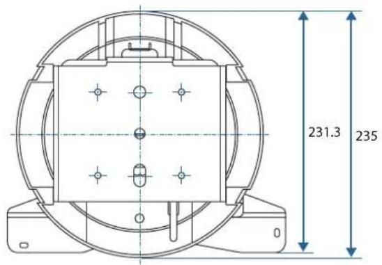
| Dimensions (with cover) | 266 x 231.3 x 235 mm (L x W x H) |
| Bracket weight | 2.7 kg |
| Maximum load capacity | 10 kg |
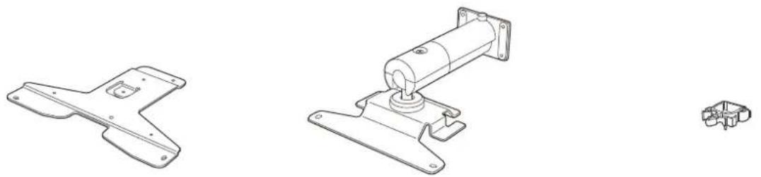
| Package contents | Projector plate, arm, cable clamp, fixing plates A and B, security cable, hex keys M4 and M6, screws |
| Material | Steel and plastic |
| Mounting holes | 2 holes for M10 anchor bolts or wood screws dia. 5.1 mm |
| Safety | Security cable included, professional installation recommended |
| Adjustments | Orientation and angle via ball joint, tightening with M6 screw |
| Maintenance | Clean with a dry cloth, no solvents |
| Warranty | Consult the user guide for terms |
Frequently Asked Questions - ELPMB60 EPSON
User questions about ELPMB60 EPSON
0 question about this device. Answer the ones you know or ask your own.
Ask a new question about this device
Download the instructions for your Video projector in PDF format for free! Find your manual ELPMB60 - EPSON and take your electronic device back in hand. On this page are published all the documents necessary for the use of your device. ELPMB60 by EPSON.
USER MANUAL ELPMB60 EPSON
natural_image
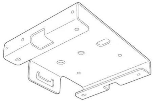
Technical line drawing of a mechanical support base with mounting flanges and internal components (no text or symbols)Installation Guide
natural_image
Technical line drawing of a mechanical support base with mounting feet and internal components (no text or symbols)
Safety Instructions
This guide explains how to install the projector on the ceiling, on a wall, or on the floor using the ELPMB60 ceiling mount/floor stand supplied.
Make sure you read this guide carefully to use the installation mounts and the projector safely. Incorrect handling that ignores instructions in this guide could damage this product or could result in personal injury or property damage. Keep this installation guide at hand for future reference.
Regarding how to handle the projector, read the User's Guide and Safety Instructions supplied with your projector and follow the instructions in these documents.
Type of Installation
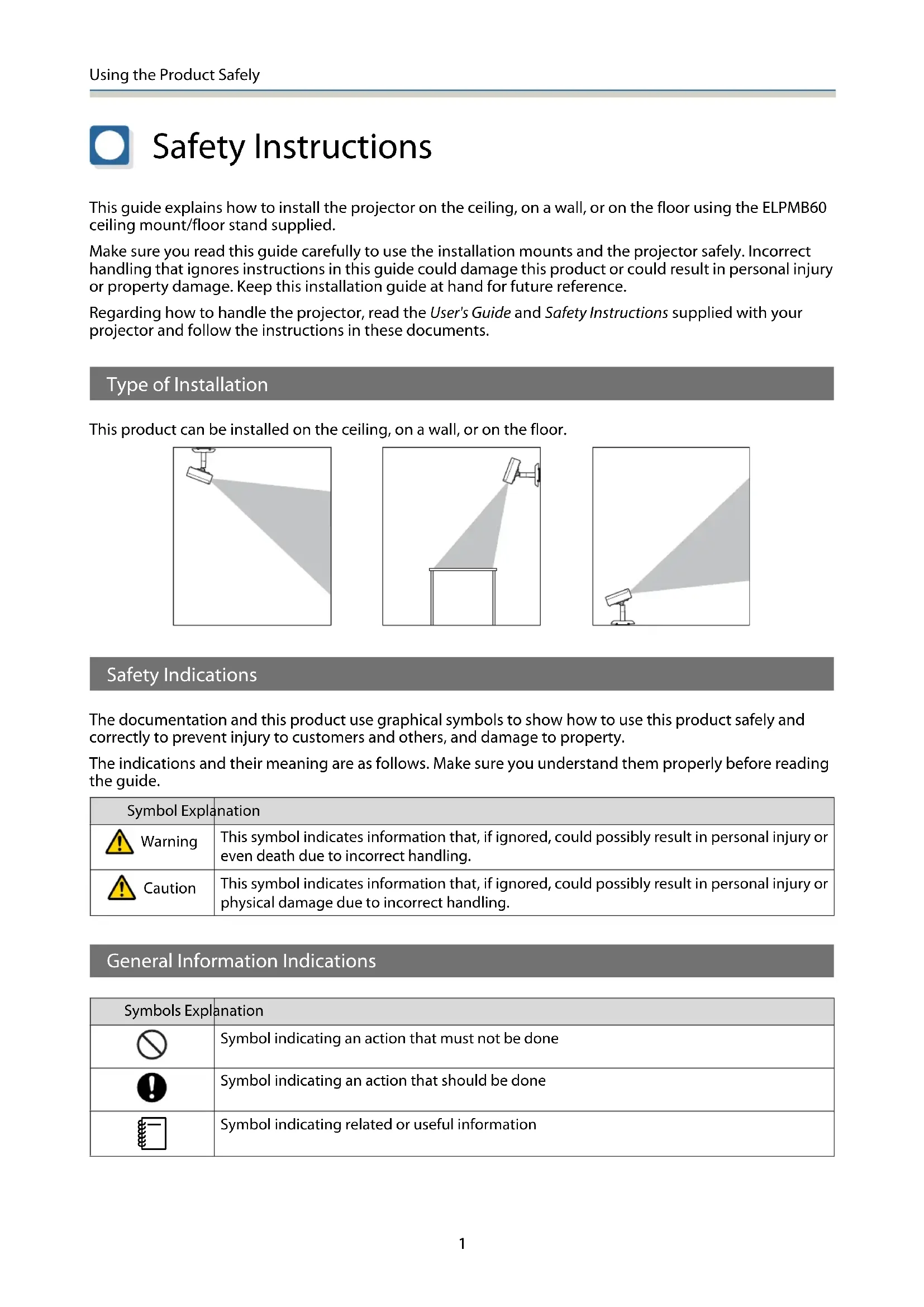
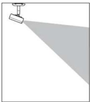
This product can be installed on the ceiling, on a wall, or on the floor.
natural_image
Simple line drawing of a projector with a spotlight and shadow (no text or symbols)
natural_image
Simple line drawing of a spotlight beam projecting onto a rectangular base (no text or symbols)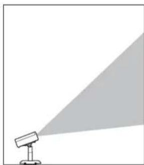
natural_image
Simple line drawing of a projector with a triangular light source, no text or symbols presentSafety Indications
The documentation and this product use graphical symbols to show how to use this product safely and correctly to prevent injury to customers and others, and damage to property.
The indications and their meaning are as follows. Make sure you understand them properly before reading the guide.
| Symbol Explanation | |
 Warning Warning | This symbol indicates information that, if ignored, could possibly result in personal injury or even death due to incorrect handling. |
 Caution Caution | This symbol indicates information that, if ignored, could possibly result in personal injury or physical damage due to incorrect handling. |
General Information Indications
| Symbols Explanation | |
 | Symbol indicating an action that must not be done |
 | Symbol indicating an action that should be done |
 | Symbol indicating related or useful information |
Precautions on Installing the Projector
 Warning Warning | |
| Installing the projector should only be performed by a professional with the necessary skills and know-how.If installation work is not carried out correctly, the mount or the projector could fall or topple over causing injury or accident to occur. |  |
| Follow the instructions in this guide when performing installation work.If the instructions are not followed, the mount or the projector could fall or topple over causing injury or accident to occur. |  |
| Check that the structure and material of the installation location are strong enough before installing, and use the optimum installation method.If work is not carried out correctly, the mount or the projector could fall or topple over causing injury or accident to occur. |  |
| Installing on the ceiling or wall should be performed by at least two people. Also, make sure you have a secure, stable footing so that you do not drop the mount or the projector. |  |
| When installing in a high location such as a ceiling, wall, or on a shelf, make sure you attach the safety wire supplied to the mount and the projector to prevent the projector from falling. |  |
| Do not attach anything to this mount except for EPSON projector's that are compatible with this product.If you attach a projector that is not compatible with this product, the mount could fall, topple over, or be damaged causing death or serious injury.Check the catalog for projectors that are compatible with this product. |  |
| When installing, make sure you install a breaker (with a rated current of 10 A or less) in a location within reach.If any problems occur during installation, turn off the internal wiring immediately. |  |
| Note the following when handling the power cable. Otherwise, it could cause a fire or electric shock.Do not handle the plug with wet handsDo not use a damaged or modified power cableDo not apply excessive force to the power cableDo not trap the cable between parts of the mount and so on during installation |  |
| Do not wind cables around the projector or the mount. | [8XA0] |
| When wiring cables and so on, route the cables so that it avoids the screws and bolts.If the cables come into contact with screws or bolts, it could cause a fire or electric shock to occur. | [303Y] |
| Make sure you tighten the screws or bolts completely when installing.If they are not tightened completely, the mount or the projector could fall or topple over causing injury or accident to occur. |  |
| Do not loosen or remove screws for no reason while installing or removing this product. |  |
| When securing the mount, do not use adhesives to prevent the screws from loosening, and do not use lubricants, oils, and so on.If you use adhesives to prevent the screws from loosening, or if you use things such as lubricants or oils, the mount or the projector case may crack and fall or topple over causing an injury or an accident. | |
| Do not hang from the mount or the projector, and do not place heavy objects on them. Otherwise, the mount or the projector may fall or topple over and could cause death or injury. | |
| Do not apply excessive force to the projector or the mount when installing.Otherwise, the mount or the projector may be damaged and could cause death or injury. | |
| Do not install in the following situations. Contact your local dealer or Epson Service Call Center.• If the product has been dropped or damaged before or during installation• If the mount is abnormal or damaged | |
Warnings and Cautions on the Installation Locations
 Warning Warning | |
| Check the structure and material of the surface to which the mount will be installed, and use the optimum installation method. |  |
| Make sure the surface to which the mount will be installed is strong enough. |  |
| Do not install the mount or projector in an unstable location where it might be subjected to vibrations or shocks.The surface to which the mount is attached may be damaged. Also, the mount or projector may fall or topple over and cause an injury or accident to occur. |  |
| Do not install in a location that is not strong enough to bear the load or that is slanted.The installation location needs to be strong enough to support the projector and this product. Check the weight of the projector and this product before installation, perform calculations of allowable weight and so on, and then install them securely. |  |
| Do not install or use the projector in locations where it could be exposed to rain or water, such as outdoors, in baths or shower rooms.Otherwise, it could cause a fire or electric shock. |  |
| Do not use the projector in a location subject to combustible or explosive gas.If the inside of the projector gets too hot, it could ignite and cause a fire. |  |
| Do not cover the projector's air intake vent or air exhaust vent.If either of the vents are covered, the projector's internal temperature could rise and cause a fire. |  |
 Caution Caution | |
| Do not install the projector in a location outside the projector's operating temperature range.Such an environment may damage the projector. | |
| Install it away from air outlets such as air conditioners.If the air from an air conditioner and so on flows directly over the projector, the temperature rises and the projector may not operate correctly. | |
| Install it away from fluorescent lights.Some kinds of fluorescent lights could interfere with the remote control of the projector. | |
| Install it in a location where strong light such as fluorescent light and direct sunlight does not shine on the remote receiver.If strong rays of light shine on the remote receiver, remote control operations may not be performed correctly. | |
| Make sure you install the projector in a location free from excessive dust and humidity to prevent the lens or internal components from becoming dirty. | |
| Do not install the projector in a location subject to high levels of dust or humidity, or in a location subject to smoke or steam.Otherwise, it could cause a fire or electric shock to occur. The projector's case could also deteriorate and be damaged causing the projector to fall from the mount.Examples of environments that could cause the projector to fall due to case deterioration• Locations subject to excessive smoke or airborne oil particles, such as factories or kitchens• Locations containing volatile solvents or chemicals, such as factories or laboratories• Locations where the projector could be subjected to detergents or chemicals, such as factories or kitchens• Locations in which aroma oils are often used, such as relaxation rooms• Near devices that produce excessive smoke, airborne oil particles, or foam at events | |
Precautions on Handling After Installing
 Warning Warning | |
| Never loosen the screws or bolts after installation.Make sure that you check for any loose screws or bolts on a regular basis, and if any are loose,tighten them completely. If they are not tightened completely, the mount or the projector couldfall or topple over causing injury or accident to occur. | |
| Do not apply excessive force to the mount or hang from the mount. | |
| Never disassemble or remodel this product except as instructed in this guide. | |
| Do not use a wet cloth or solvents such alcohol, benzine, or thinner, when cleaning theproduct.Water could get into the projector or the case could deteriorate and crack causing an electric shockto occur. | |
Using the Product Safely
Safety Instructions .... 1
Type of Installation....1
Safety Indications....1
General Information Indications....1
Precautions on Installing the Projector.....2
Warnings and Cautions on the Installation
Locations 3
Precautions on Handling After Installing ..... 4
Preparing the Projector
Package Contents 6
Installation Procedure
Attaching the Mount to the Projector
8
Attaching the Projector Plate ....8
Attaching the Arm Unit .....9
Installing the Safety Wire .... 11
Attaching the Projector to the
Installation Location 12
Determining the installation position.....12
Mounting hole positions and dimensions 12
When the mounting location is concrete....12
When the mounting location is wood.....13
Attaching the Ceiling Mount/Floor Stand Plate 13
Attaching the Arm Unit to the Ceiling Mount/Floor Stand Plate....15
Connecting Cables 16
Attaching the Mount Cover ..... 17
Adjusting the Orientation of the
Projector 20
Appendix
Specification 22
Appearance 22

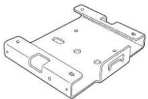
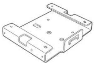
Package Contents
Check that you have all of the following accessories before you start work.
natural_image
Technical line drawings of mechanical components including a bracket, motor, and housing (no text or symbols)Projector plate Arm unit Cable clamp
natural_image
Technical line drawing of a mechanical housing or bracket (no text or symbols)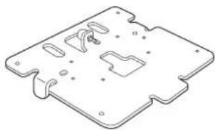
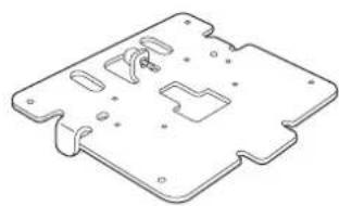
natural_image
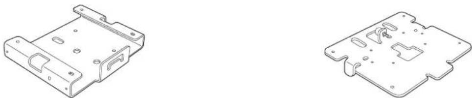
Isometric technical drawing of a mechanical component with cutouts and mounting holes (no text or symbols)Ceiling mount/Floor stand plate A Ceiling mount/Floor stand plate B
natural_image
Technical line drawing of a mechanical component (no text or symbols)
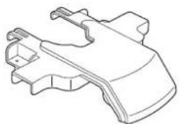
natural_image
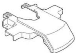
Simple line drawing of a curved, segmented object resembling a mechanical part or housing (no text or symbols)Mount cover A Mount cover B
natural_image
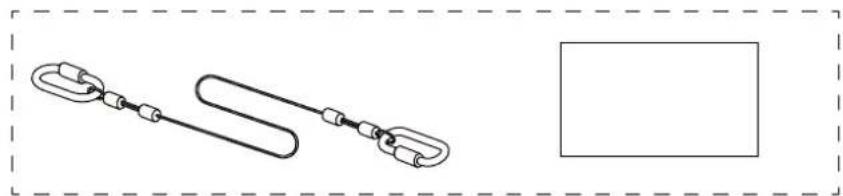
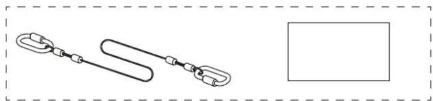
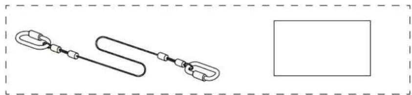
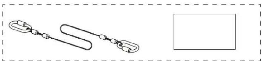
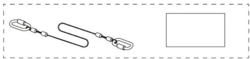
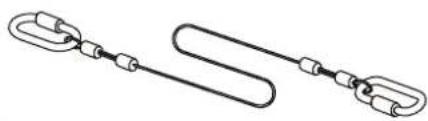
Simple line drawing of a chain link with a loop, enclosed in a dashed border (no text or symbols)Safety wire set (safety wire (500 mm) and User's Guide)
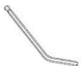
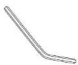
Hexagonal wrench (M4 ball point) Hexagonal wrench (M6)
| Shape Name | Quantity | Application | |
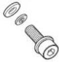 | M4 x 14 mm hexagonal recessed head screw (with washer): black | 4 Secures | ceiling mount/floor stand plate B. |
| 4 Secures | the arm unit to the ceiling mount/floor stand plate. | ||
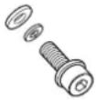 | M4 x 10 mm hexagonal recessed head screw (with washer): silver | 4 Secures | the projector plate to the projector. |
| 3 Secures | the arm unit to the projector plate. | ||
| 6 Secures | the mount cover. | ||

Attaching the Mount to the Projector
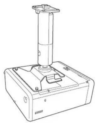
Attach the projector plate and arm unit to the base of the projector.

Caution
Make sure you use the screws supplied when attaching the mount to the projector.
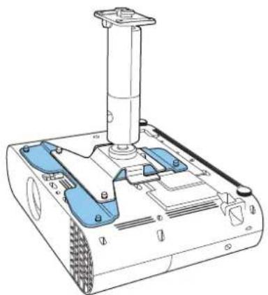
Attaching the Projector Plate
You may not need to attach the projector plate depending on the model you are using. Go to the arm unit installation procedure.
natural_image
Technical line drawing of a robotic device with blue and white components (no text or symbols)
natural_image
Technical line drawing of a mechanical device with a cylindrical component mounted on a base (no text or symbols visible)Projector plate necessary Projector plate un-necessary

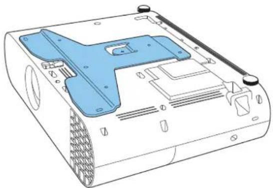
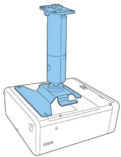
Place the projector plate on the base of the projector.
Align the screw holes on the projector's mount fixing point with the screw holes on the projector plate.
natural_image
Technical line drawing of a mechanical device with blue plastic casing and mounting holes (no text or symbols)2
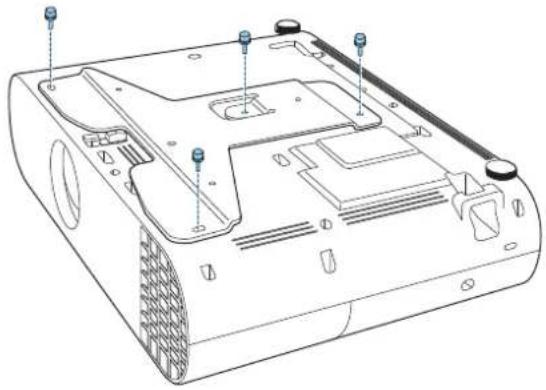
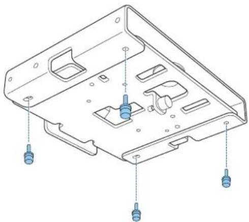
Secure the projector plate using the M4 x 10 mm screws supplied (x4).
natural_image
Technical line drawing of a computer monitor chassis with mounting holes and ventilation slots (no text or labels)Attaching the Arm Unit
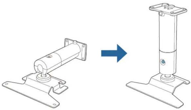
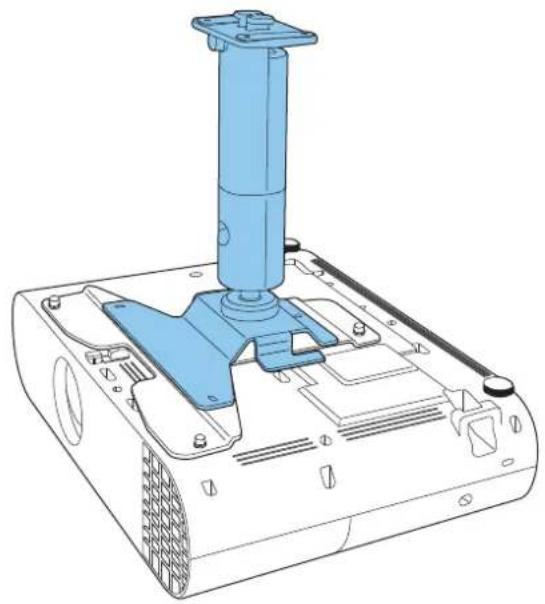
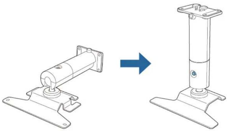
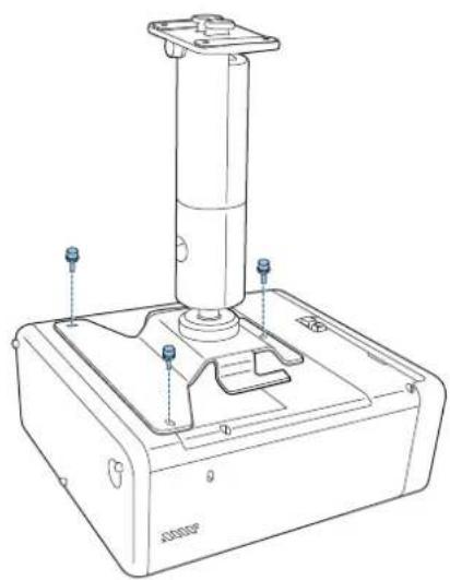
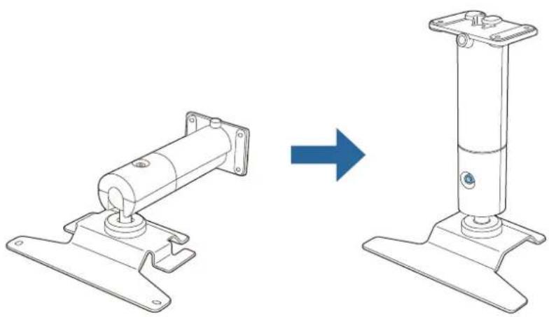
1
Straighten the arm unit and tighten the screws.
natural_image
Technical line drawing showing a mechanical assembly before and after transformation (no text or symbols)2
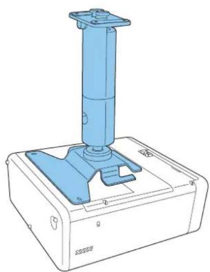
Place the arm unit on the projector.
Align the screw holes on the projector plate or the screw holes on the projector with the screw holes on the arm unit.
natural_image
Technical line drawing of a mechanical device with a blue lever and base mount (no text or symbols)
natural_image
Technical line drawing of a blue industrial device with a vertical cylindrical component mounted on a base (no text or symbols visible)With projector plate Without projector plate
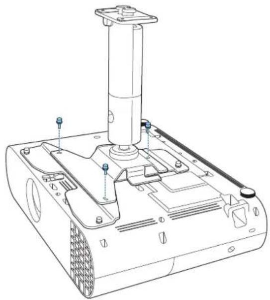
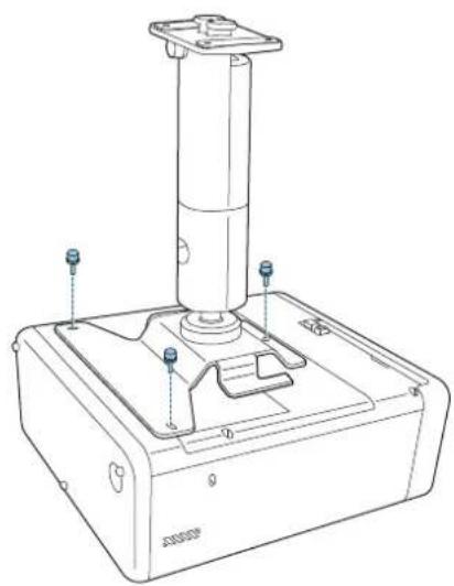
3
Secure the arm unit to the projector using the M4 x 10 mm screws supplied (x3).
natural_image
Technical line drawing of a mechanical device with mounting feet and a cylindrical component (no text or symbols)
natural_image
Technical line drawing of a mechanical device with a cylindrical component and mounting base (no text or symbols)With projector plate Without projector plate

Installing the Safety Wire
When installing in a high location such as a ceiling, wall, or on a shelf, after attaching the arm unit, install the safety wire supplied to prevent the projector from falling.
For details on the installation procedure, see the User's Guide supplied with the safety wire set.

Attaching the Projector to the Installation Location
Determining the installation position
Check the position where you want to project the image, and determine the mounting position for the Ceiling mount/Floor stand.
Make sure you take into consideration the structure (strength and so on) of the installation location on which you will install the Ceiling mount/Floor stand.

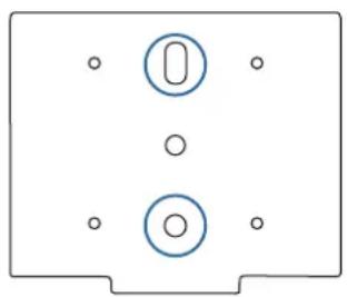
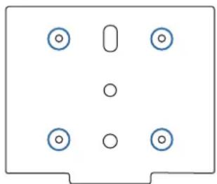
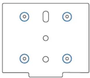
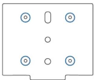
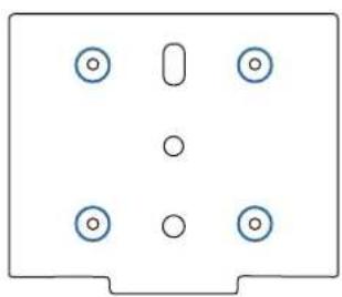
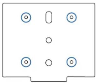
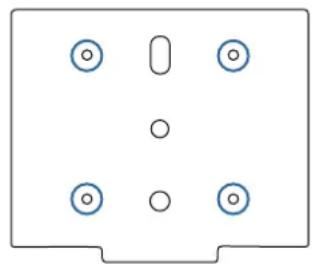
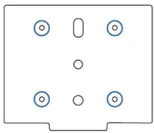
Mounting hole positions and dimensions
1
natural_image
Simple diagram of a device with two circular components and four holes, no text or symbols present.2

natural_image
Simple diagram of a rectangular panel with six circular holes and a vertical oval cutout (no text or symbols)
Anchor bolt mounting hole (M10)

Wood screw mounting hole (nominal diameter 5.1)

When the mounting location is concrete
Use two anchor bolts to attach the mount to a concrete surface. Make sure you acquire commercially available anchor bolts.

Warning
- Check in advance that the concrete for the installation area can withstand the combined mass of this product and the projector, as well as any side-to-side movements that may occur due to earthquakes and so on. If the concrete is fragile or has deteriorated over time, be sure to reinforce it securely with rebar and so on.
- Anchors must be installed in accordance with standards and methods specified by the manufacturers of the material to ensure that they do not break, loosen, or become misaligned.
- Be sure to tighten all screws securely when installing or after completing angle adjustments.
After tightening screws, tighten them further to make sure that there are definitely no loose screws. - Note that we cannot accept responsibility for any accidents that occur if this product falls due to insufficient strength and so on in the installation area.
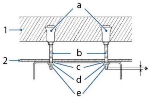
1: Concrete
2: Ceiling surface
a: Female threading type anchor
b: Eye bolt
c: Flat washer
d: Spring washer
e: Hexagonal nut
*: At least 3 ridges of the screw should be visible.
However, do not extend more than 9 mm as this will touch the mount.
When the mounting location is wood

Warning
When installing using wood screws, make sure that the base is at least 20 mm thick.
Attaching the Ceiling Mount/Floor Stand Plate
1
Drill mounting holes in the installation location.
2
Attach ceiling mount/floor stand plate A to the ceiling.
Make sure you acquire commercially available items to be used for installation.
natural_image
Technical line drawing of a metal bracket component (no text or symbols)
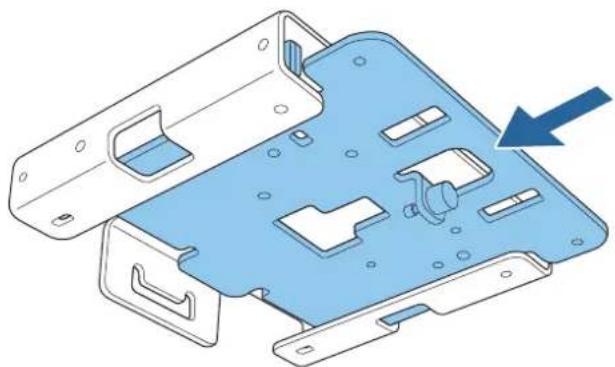
Insert ceiling mount/floor stand plate B into plate A.
natural_image
3D diagram of a blue plastic mechanical housing with internal compartments and mounting holes, showing a blue arrow pointing to a component (no text or symbols present)
Tighten the M4 x 14 mm screws supplied (x4) with the hexagonal wrench (M4 ball point), and secure ceiling mount/floor stand plate B.
natural_image
Technical line drawing of a mechanical housing component with mounting holes and internal slots (no text or symbols)Attaching the Arm Unit to the Ceiling Mount/Floor Stand Plate
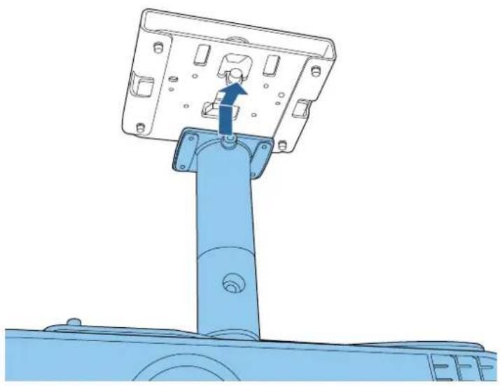
Insert the arm unit into the gap provided in ceiling mount/floor stand plate B.
Slide it to the front and align the screw holes in ceiling mount/floor stand plate B with the screw holes in the arm unit.
natural_image
Technical line drawing of a mechanical assembly with a blue component and mounting bracket (no text or symbols)2 Tighten the screws for ceiling mount/floor stand plate B to temporarily secure the arm unit.
natural_image
Technical line drawing of a mechanical assembly with a blue arrow indicating rotation or movement (no text or symbols)3 Tighten the M4 x 14 mm screws supplied (x4) with a hexagonal wrench (M4 ball point) to secure the arm unit.
natural_image
Technical line drawing of a mechanical assembly with mounting holes and a central component (no text or symbols)
Connecting Cables
Connect the necessary cables to the projector's connection ports.
Check the Projector's User's Guide for information on the connection ports.

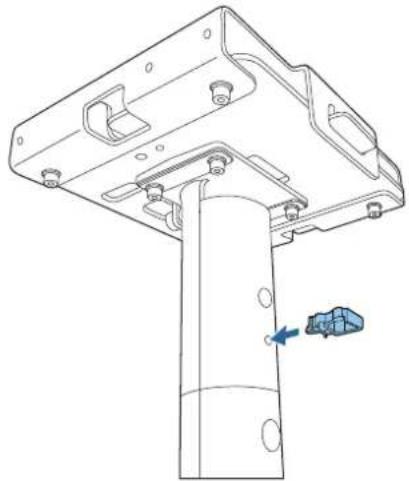
Attaching the Mount Cover

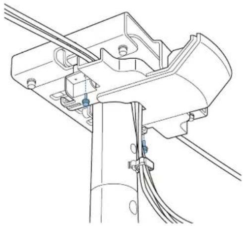
Attach the cable clamp to the arm unit.
Insert the cable clamp to fit through the holes in the arm unit.
natural_image
Technical line drawing of a mechanical assembly with a vertical component and a blue arrow indicating a force or adjustment (no text or symbols present)
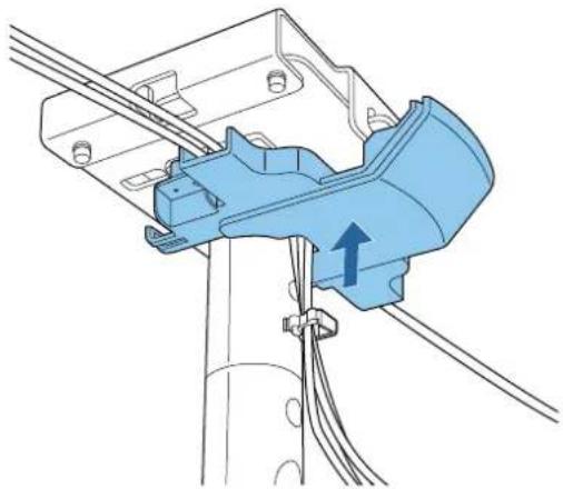
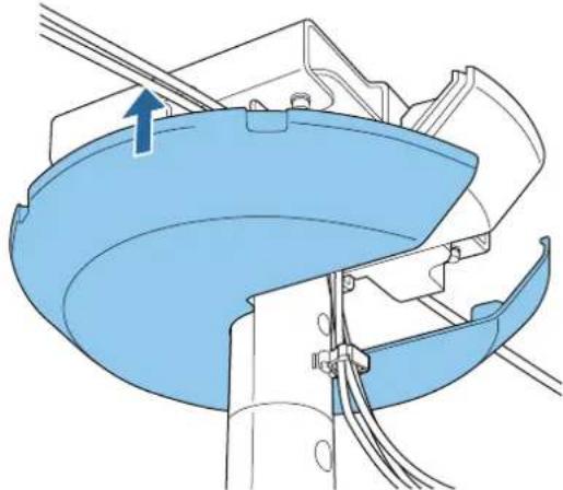
Attach mount cover A to the ceiling mount/floor stand plate.
natural_image
Technical diagram of a mechanical assembly with blue component and wiring (no text or symbols)
Route cables through the cabling paths or cable clamps if necessary. If the cables are thick or if there are a lot of cables, connect them directly without passing them through the cabling path or cable clamps.
3
Secure mount cover A using the M4 x 10 mm screws supplied (x2).
natural_image
Technical line drawing of a mechanical assembly with wires and connectors (no text or symbols)
Caution
Make sure the cables do not get trapped by the mount cover. If you tighten the screws while the cables are trapped between the cover and the mount, the cables may be disconnected.
4
Attach mount cover B.
Hook it over mount cover A and secure it temporarily.
natural_image
Technical diagram of a mechanical assembly with blue components and wires, no visible text or symbols5
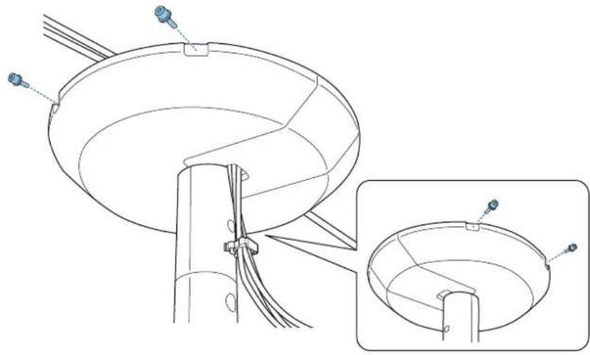
Secure mount cover B using the M4 x 10 mm screws supplied (x4).
Align the screw holes while supporting mount cover B from underneath.
natural_image
Technical line drawing of a mechanical assembly with a circular component and a magnified inset showing internal structure (no text or symbols)
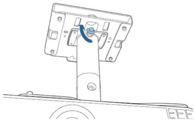
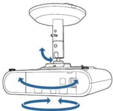
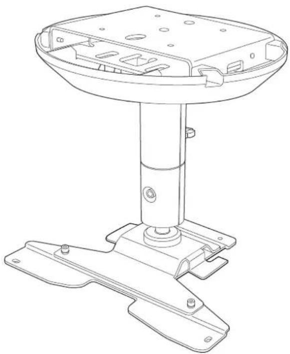
Adjusting the Orientation of the Projector
You can use the ball joint on the projector support section to adjust the orientation and the angle of the projector.
The range of angles available varies depending on the model you are using. For more details, see the User's Guide supplied with the projector.
natural_image
Diagram of a mechanical device with rotating arrows indicating rotational motion (no text or symbols)Press the power button on the projector or the remote control.
The projector turns on.

Caution
Before turning on the projector, make sure the mount is firmly secured.
Loosen the screw for the arm unit's ball joint with a hexagonal wrench (M6).
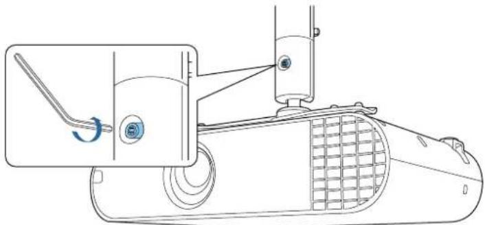
natural_image
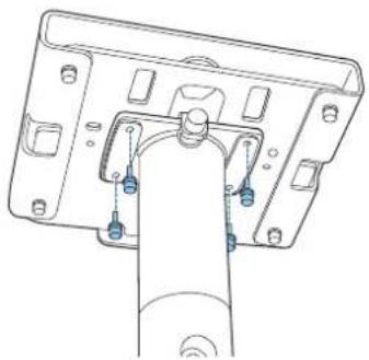
Technical line drawing of a mechanical device with a lever and meshed base (no text or symbols)Adjust the orientation of the projector.
Make sure you support the projector from underneath while adjusting the orientation.

When you have finished making adjustments, securely tighten the screw for the ball joint section with a hexagonal wrench (M6).
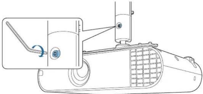
natural_image
Technical line drawing of a mechanical device with a lever and adjustment knob (no text or symbols)
• After making adjustments, make sure you tighten the screws of the ball joint completely. If they are not tightened completely, the angle of the projector will change shifting the position of the image.
- After adjusting the orientation of the projector, adjust the size and focus of the projected image. For more details, see the User's Guide supplied with the projector.

Specification
| Item Specification | |
| Mass (projector plate, arm unit, ceiling mount/floor stand plate A/B, mount cover A/B) | Approx. 2.7 kg |
| Maximum load capacity Approx. 10.0kg |
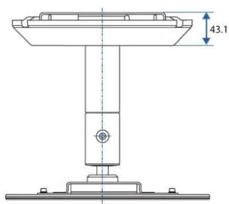
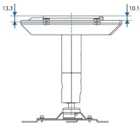
Appearance
[Unit: mm]
Without the mount cover
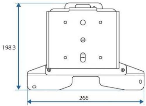
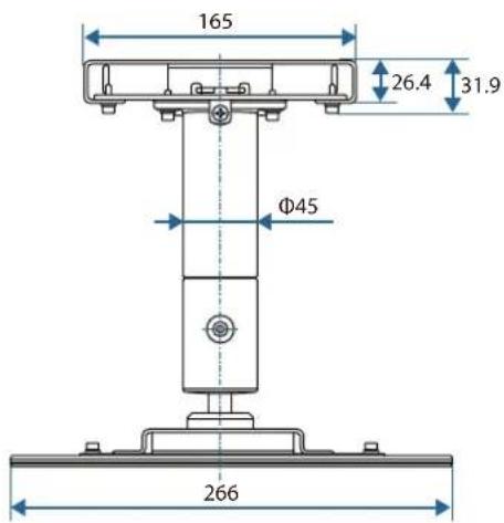
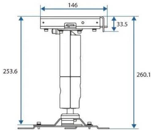
With the mount cover attached
©SEIKO EPSON CORPORATION 2019. All rights reserved.
ELPMB60
natural_image
Technical line drawing of a mechanical support base with mounting feet and internal components (no text or symbols)
natural_image
Simple line drawing of a spotlight beam projecting onto a wall (no text or symbols)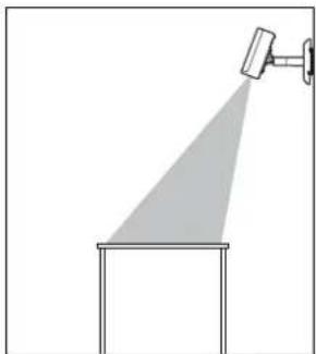
natural_image
Simple line drawing of a spotlight beam projecting onto a rectangular base (no text or symbols)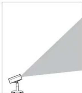
natural_image
Simple line drawing of a spotlight emitting a light beam (no text or symbols)natural_image
Technical line drawings of mechanical components including a bracket, motor, and housing (no text or symbols)natural_image
Technical line drawing of a mechanical housing or bracket (no text or symbols)
natural_image
Isometric technical drawing of a mechanical component with cutouts and mounting holes (no text or symbols)natural_image
Technical line drawing of a mechanical component (no text or symbols)
natural_image
Simple line drawing of a curved mechanical component or bracket (no text or symbols)Cache de support A Cache de support B

natural_image
Simple line drawing of a chain link with a loop, enclosed in a dashed border (no text or symbols)natural_image
Technical line drawing of a robotic device with blue and white components (no text or symbols)
natural_image
Technical line drawing of a mechanical device with a cylindrical component mounted on a base (no text or symbols visible)natural_image
Technical line drawing of a mechanical device with blue internal components and mounting holes (no text or symbols)2
natural_image
Technical line drawing of a computer monitor chassis with mounting holes and ventilation slots (no text or labels)Fixer le bras
1
natural_image
Technical line drawing showing a mechanical assembly before and after transformation (no text or symbols)
natural_image
Technical line drawing of a mechanical device with a blue lever and base mount (no text or symbols)
natural_image
Technical line drawing of a blue industrial device with a vertical cylindrical component mounted on a base (no text or symbols visible)natural_image
Technical line drawing of a mechanical device with mounting feet and a vertical cylindrical component (no text or symbols)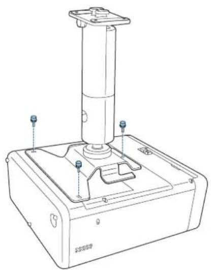
natural_image
Technical line drawing of a mechanical device with a cylindrical component and mounting base (no text or symbols)natural_image
Simple diagram of a device with two circular components and four holes, no text or symbols present.2

natural_image
Simple diagram of a rectangular panel with six circular holes and a vertical oval cutout (no text or symbols)natural_image
Technical line drawing of a metal bracket with mounting holes and cutouts (no text or symbols)
natural_image
3D diagram of a blue plastic mechanical housing with internal compartments and mounting holes, showing a blue arrow pointing to a component (no text or symbols present)
natural_image
Technical line drawing of a mechanical housing component with mounting holes and internal slots (no text or symbols)natural_image
Technical line drawing of a mechanical assembly with a blue component and directional arrow (no text or symbols)natural_image
Technical line drawing of a mechanical assembly with a blue arrow indicating direction (no text or symbols)natural_image
Technical line drawing of a mechanical assembly with mounting holes and a central component (no text or symbols)
natural_image
Technical line drawing of a mechanical assembly with a vertical support and mounting bracket (no text or symbols)
natural_image
Technical diagram of a mechanical assembly with blue component and wiring (no text or symbols)
natural_image
Technical line drawing of a mechanical assembly with no visible text or symbols
Attention
natural_image
Technical diagram of a mechanical assembly with blue components and wires, no visible text or symbols
natural_image
Technical line drawing of a satellite dish antenna with attached cable and base, showing internal structure and component details (no text or symbols)
natural_image
Diagram of a mechanical device with rotating arrows indicating rotational motion (no text or symbols)1
natural_image
Technical line drawing of a mechanical device with a lever and meshed base (no text or symbols)3
natural_image
Technical line drawing of a mechanical device with a lever and wheel assembly (no text or symbols)
©SEIKO EPSON CORPORATION 2019. All rights reserved.
ELPMB60
natural_image
Technical line drawing of a mechanical support base with mounting feet and internal components (no text or symbols)
natural_image
Simple line drawing of a projector with a spotlight and shadow (no text or symbols)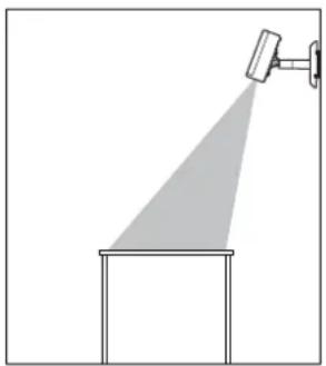
natural_image
Simple line drawing of a spotlight beam projecting onto a rectangular platform (no text or symbols)
natural_image
Simple line drawing of a projector with a triangular light source, no text or symbols presentSicherheitshinweise
natural_image
Technical line drawings of mechanical components including a bracket, motor, and housing (no text or symbols)natural_image
Technical line drawing of a mechanical housing or enclosure component (no text or symbols)
natural_image
Isometric line drawing of a mechanical component with cutouts and mounting holes (no text or symbols)natural_image
Technical line drawing of a mechanical component (no text or symbols)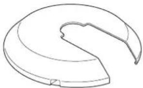
natural_image
Simple line drawing of a curved mechanical component or bracket (no text or symbols)Montageabdeckung A Montageabdeckung B
natural_image
Simple line drawing of a chain link with a loop, enclosed in a dashed border (no text or symbols)natural_image
Two identical L-shaped metal bars, side by side, drawn with thin hatching on a white background (no text or symbols)natural_image
Technical line drawing of a robotic device with blue and white components (no text or symbols)
natural_image
Technical line drawing of a mechanical device with a cylindrical component mounted on a base (no text or symbols visible)natural_image
Technical line drawing of a device casing with blue internal components and mounting holes (no text or symbols)2
natural_image
Technical line drawing of a computer monitor chassis with mounting holes and ventilation slots (no text or labels)natural_image
Technical line drawing showing a mechanical assembly before and after transformation (no text or symbols)
natural_image
Technical line drawing of a mechanical device with a blue lever and base plate (no text or symbols)
natural_image
Technical line drawing of a blue industrial device with a vertical cylindrical component mounted on a base (no text or symbols visible)natural_image
Technical line drawing of a mechanical device with a cylindrical component and mounting base (no text or symbols)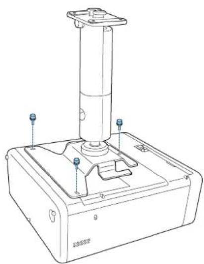
natural_image
Technical line drawing of a mechanical device with a cylindrical component and mounting base (no text or symbols)natural_image
Simple diagram of a device with two circular buttons and four dots, no text or symbols present.2
natural_image
Pure electrical circuit lines without any symbolsnatural_image
Technical line drawing of a metal bracket with mounting holes and cutouts (no text or symbols)
natural_image
3D diagram of a blue plastic mechanical housing with internal compartments and mounting holes, showing a blue arrow pointing to a component (no text or symbols present)
natural_image
Technical line drawing of a mechanical housing component with blue connectors and mounting holes (no text or symbols)natural_image
Technical line drawing of a mechanical assembly with a blue component and arrow indicating direction (no text or symbols)natural_image
Technical line drawing of a mechanical assembly with a blue arrow indicating rotation or movement (no text or symbols)natural_image
Technical line drawing of a mechanical assembly with mounting holes and a central component (no text or symbols)
Kabel anschließen
natural_image
Technical line drawing of a mechanical assembly with a vertical component and a blue arrow indicating a force or adjustment (no text or symbols present)
natural_image
Technical diagram of a mechanical assembly with blue component and wiring (no text or symbols)
natural_image
Technical line drawing of a mechanical assembly with wires and components (no text or symbols)
Achtung
natural_image
Technical diagram of a mechanical assembly with blue components and wires, no visible text or symbols
natural_image
Technical line drawing of a satellite dish antenna with attached cable and sensor components (no text or symbols)
natural_image
Diagram of a mechanical device with rotating arrows indicating rotational motion (no text or symbols)1
natural_image
Technical line drawing of a mechanical device with a lever and gear mechanism (no text or symbols)3
natural_image
Technical line drawing of a mechanical device with a lever and adjustment knob (no text or symbols)
©SEIKO EPSON CORPORATION 2019. All rights reserved.
ELPMB60
natural_image
Technical line drawing of a mechanical support base with mounting feet and internal components (no text or symbols)
natural_image
Simple line drawing of a spotlight with a triangular shadow and a circular head (no text or symbols)
natural_image
Simple line drawing of a spotlight beam projecting onto a rectangular base (no text or symbols)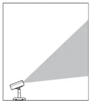
natural_image
Simple line drawing of a spotlight emitting a light beam (no text or symbols)natural_image
Technical line drawings of mechanical components including a bracket, motor, and housing (no text or symbols)natural_image
Technical line drawing of a mechanical housing or bracket (no text or symbols)
natural_image
Isometric technical drawing of a mechanical component with cutouts and mounting holes (no text or symbols)natural_image
Technical line drawing of a mechanical component (no text or symbols)
natural_image
Simple line drawing of a curved, segmented object resembling a mechanical part or housing (no text or symbols)natural_image
Simple line drawing of a chain link with a loop, enclosed in a dashed border (no text or symbols)natural_image
Two identical L-shaped metal rods with hatching, isolated on white background (no text or symbols)natural_image
Technical line drawing of a robotic device with blue and white components (no text or symbols)
natural_image
Technical line drawing of a mechanical device with a cylindrical component mounted on a base (no text or symbols visible)natural_image
Technical line drawing of a device casing with blue internal components and mounting holes (no text or symbols)2
natural_image
Technical line drawing of a computer monitor chassis with mounting holes and ventilation slots (no text or symbols)natural_image
Technical line drawing of a mechanical assembly showing a left-side component transforming into a right-side vertical component (no text or symbols)
natural_image
Technical line drawing of a mechanical device with a blue lever and base plate (no text or symbols)
natural_image
Technical line drawing of a blue industrial device with a vertical cylindrical component mounted on a base (no text or symbols visible)natural_image
Technical line drawing of a mechanical device with mounting feet and a vertical cylindrical component (no text or symbols)
natural_image
Technical line drawing of a mechanical device with a cylindrical component and base (no text or symbols)natural_image
Simple diagram of a device with two circular components and four holes, no text or symbols present.2
natural_image
Simple diagram of a rectangular panel with six circular holes and a vertical oval cutout (no text or symbols)natural_image
Technical line drawing of a metal bracket with mounting holes and cutouts (no text or symbols)
natural_image
3D diagram of a blue plastic mechanical housing with internal compartments and mounting holes, showing a blue arrow pointing to a component (no text or symbols present)
natural_image
Technical line drawing of a mechanical housing component with mounting holes and internal slots (no text or symbols)natural_image
Technical line drawing of a mechanical assembly with a blue component and directional arrow (no text or symbols)2
natural_image
Technical line drawing of a mechanical assembly with a blue arrow indicating rotation or movement (no text or symbols)3
natural_image
Technical line drawing of a mechanical assembly with mounting holes and a vertical rod (no text or symbols)
natural_image
Technical line drawing of a mechanical assembly with a cylindrical component and mounting bracket (no text or symbols)
natural_image
Technical diagram of a mechanical assembly with blue component and wiring (no text or symbols)
natural_image
Technical line drawing of a mechanical assembly with no visible text or symbols
Attenzione
natural_image
Technical diagram of a mechanical assembly with blue components and wires, no visible text or symbols
natural_image
Technical line drawing of a mechanical assembly with a central component and an inset showing a circular component (no text or symbols)
natural_image
Diagram of a mechanical device with rotating arrows indicating rotational motion (no text or symbols)1
natural_image
Technical line drawing of a mechanical device with a lever and adjustment knob (no text or symbols)3
natural_image
Technical line drawing of a mechanical device with a lever and adjustment knob (no text or symbols)
©SEIKO EPSON CORPORATION 2019. All rights reserved.
ELPMB60
Guía de instalación

natural_image
Technical line drawing of a mechanical support base with mounting feet and internal components (no text or symbols)
natural_image
Simple line drawing of a projector with a spotlight and shadow (no text or symbols)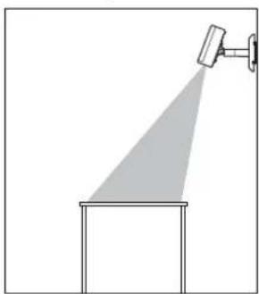
natural_image
Simple line drawing of a spray gun mounted on a platform, no text or symbols present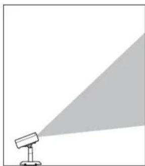
natural_image
Simple line drawing of a projector with a light beam projecting onto it (no text or symbols)natural_image
Technical line drawings of mechanical components including a bracket, motor, and housing (no text or symbols)natural_image
Technical line drawing of a mechanical housing or enclosure component (no text or symbols)
natural_image
Isometric technical drawing of a mechanical component with cutouts and mounting holes (no text or symbols)natural_image
Technical line drawing of a mechanical component (no text or symbols)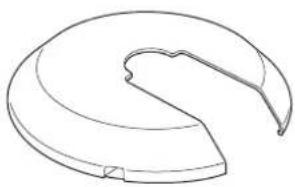
natural_image
Line drawing of a curved mechanical component or bracket (no text or symbols)natural_image
Simple line drawing of a chain link with a loop, enclosed in a dashed border (no text or symbols)natural_image
Two identical L-shaped metal bars arranged side by side (no text or symbols)natural_image
Technical line drawing of a robotic device with blue and white components (no text or symbols)
natural_image
Technical line drawing of a mechanical device with a cylindrical component mounted on a base (no text or symbols visible)natural_image
Technical line drawing of a device casing with blue internal components and mounting holes (no text or symbols)2
natural_image
Technical line drawing of a computer monitor chassis with mounting holes and ventilation slots (no text or symbols)natural_image
Technical line drawing of a mechanical assembly showing a left-side component transforming into a right-side vertical component (no text or symbols)2
natural_image
Technical line drawing of a mechanical device with a blue lever and base mount (no text or symbols)
natural_image
Technical line drawing of a blue industrial device with a vertical cylindrical component mounted on a base (no text or symbols visible)natural_image
Technical line drawing of a mechanical device with mounting holes and a cylindrical component (no text or symbols)
natural_image
Technical line drawing of a mechanical device with a cylindrical component and mounting base (no text or symbols)natural_image
Simple diagram of a device with two circular components and four holes, no text or symbols present.2

natural_image
Simple diagram of a rectangular panel with six circular holes and a vertical oval cutout (no text or symbols)natural_image
Technical line drawing of a metal bracket with mounting holes and cutouts (no text or symbols)
natural_image
3D diagram of a blue plastic mechanical housing with internal compartments and mounting holes, showing a blue arrow pointing to a component (no text or symbols present)
natural_image
Technical line drawing of a mechanical housing component with mounting holes and internal slots (no text or symbols)natural_image
Technical line drawing of a mechanical assembly with a blue component and arrow indicating direction (no text or symbols)natural_image
Technical line drawing of a mechanical assembly with a blue arrow indicating rotation or movement (no text or symbols)natural_image
Technical line drawing of a mechanical assembly with mounting holes and a central component (no text or symbols)
Conectar los cables
natural_image
Technical line drawing of a mechanical assembly with a cylindrical component and mounting bracket (no text or symbols)
natural_image
Technical diagram of a mechanical assembly with blue component and wiring (no text or symbols)
natural_image
Technical line drawing of a mechanical assembly with no visible text or symbols
Precaución
natural_image
Technical diagram of a mechanical assembly with blue components and a directional arrow (no text or symbols)
natural_image
Technical line drawing of a satellite dish antenna with attached cable and base, shown in two views (no text or symbols)
natural_image
Diagram of a mechanical device with rotating arrows indicating rotational motion (no text or symbols)1
natural_image
Technical line drawing of a mechanical device with a lever and adjustment knob (no text or symbols)3
natural_image
Technical line drawing of a mechanical device with a lever and adjustment knob (no text or symbols)
©SEIKO EPSON CORPORATION 2019. All rights reserved.
ELPMB60
natural_image
Technical line drawing of a mechanical support base with mounting feet and internal components (no text or symbols)
natural_image
Simple line drawing of a spotlight beam projecting onto a wall, with no text or symbols present.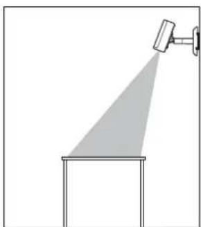
natural_image
Simple line drawing of a spotlight beam projecting onto a rectangular base (no text or symbols)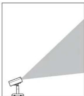
natural_image
Simple line drawing of a spotlight emitting a light beam (no text or symbols)natural_image
Technical line drawings of mechanical components including a bracket, motor, and housing (no text or symbols)natural_image
Technical line drawing of a mechanical housing or enclosure component (no text or symbols)
natural_image
Isometric technical drawing of a mechanical component with cutouts and mounting holes (no text or symbols)natural_image
Technical line drawing of a mechanical component (no text or symbols)
natural_image
Simple line drawing of a curved mechanical component or bracket (no text or symbols)Tampa do suporte A Tampa do suporte B
natural_image
Simple line drawing of a chain link with a loop, enclosed in a dashed border (no text or symbols)natural_image
Two identical L-shaped metal rods with hatching, isolated on white background (no text or symbols)Chave hexagonal (M4 ponta esférica) Chave hexagonal (M6)
natural_image
Technical line drawing of a robotic device with blue and white components (no text or symbols)
natural_image
Technical line drawing of a mechanical device with a cylindrical component mounted on a base (no text or symbols visible)natural_image
Technical line drawing of a device casing with blue internal components and mounting holes (no text or symbols)2
natural_image
Technical line drawing of a computer monitor chassis with mounting holes and ventilation slots (no text or symbols)natural_image
Technical line drawing of a mechanical assembly showing a left-side component transforming into a right-side vertical component (no text or symbols)
natural_image
Technical line drawing of a mechanical device with a blue lever and base mount (no text or symbols)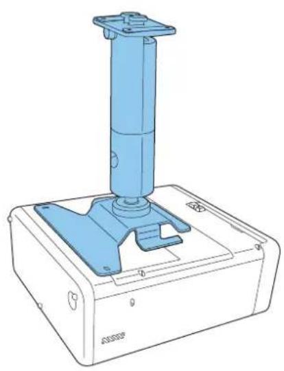
natural_image
Technical line drawing of a blue industrial device with a vertical cylindrical component mounted on a base (no text or symbols visible)natural_image
Technical line drawing of a mechanical device with a cylindrical component and mounting holes (no text or symbols)
natural_image
Technical line drawing of a mechanical device with a cylindrical component and mounting base (no text or symbols)natural_image
Simple diagram of a rectangular device with two circular buttons and four dots, no text or symbols present.2
natural_image
Simple diagram of a rectangular panel with four circular holes and an oval top, no text or symbols present.natural_image
Technical line drawing of a metal bracket with mounting holes and cutouts (no text or symbols)
natural_image
Isometric technical drawing of a blue plastic mechanical housing with mounting brackets and internal compartments, showing a blue arrow pointing to a component (no text or symbols present)
natural_image
Technical line drawing of a mechanical housing component with multiple ports and mounting holes (no text or symbols)natural_image
Technical line drawing of a mechanical assembly with a blue component and mounting bracket (no text or symbols)natural_image
Technical line drawing of a mechanical assembly with a blue arrow indicating rotation or movement (no text or symbols)natural_image
Technical line drawing of a mechanical assembly with mounting holes and a central component (no text or symbols)
Ligar os cabos
natural_image
Technical line drawing of a mechanical assembly with a vertical support and mounting bracket (no text or symbols)
natural_image
Technical diagram of a mechanical assembly with blue component and wiring (no text or symbols)
natural_image
Technical line drawing of a mechanical assembly with no visible text or symbols
Atenção
natural_image
Technical diagram of a mechanical assembly with blue components and wires, no visible text or symbols
natural_image
Technical line drawing of a mechanical assembly with a circular component and a magnified inset showing internal structure (no text or symbols)
natural_image
Diagram of a mechanical device with rotating arrows indicating rotational motion (no text or symbols)1
natural_image
Technical line drawing of a mechanical device with a lever and base plate (no text or symbols)3
natural_image
Technical line drawing of a mechanical device with a lever and adjustment knob (no text or symbols)
©SEIKO EPSON CORPORATION 2019. All rights reserved.
ELPMB60
安装手册

natural_image
Technical line drawing of a mechanical assembly with mounting base and cylindrical component (no text or symbols)
安全使用须知
natural_image
Simple line drawing of a projector with a light beam projecting onto it (no text or symbols)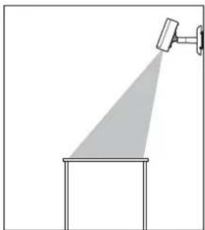
natural_image
Simple line drawing of a spotlight beam projecting onto a rectangular base (no text or symbols)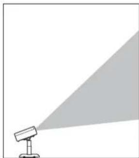
natural_image
Simple line drawing of a spotlight emitting a light beam to the right (no text or symbols)安全符号
natural_image
Technical line drawings of three mechanical components: a bracket, a cylindrical device with a knob, and a separate bracket (no text or symbols present)投影机板 支臂组件 线夹
natural_image
Technical line drawing of a mechanical housing or bracket (no text or symbols)天花板装配架/地板支架板 A
natural_image
Isometric line drawing of a mechanical component with cutouts and mounting holes (no text or symbols)天花板装配架/地板支架板 B
natural_image
Technical line drawing of a mechanical component or bracket (no text or symbols)装配架盖A装配架盖B

natural_image
Simple line drawing of a curved mechanical component or bracket (no text or symbols)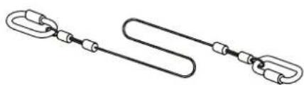
natural_image
Simple line drawing of two interlocked chain links (no text or symbols)
natural_image
Technical line drawing of a mechanical device with blue and white components (no text or symbols)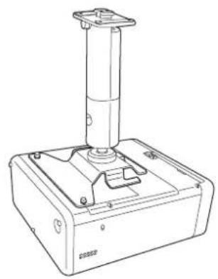
natural_image
Line drawing of a mechanical device with a vertical cylindrical component mounted on a base (no text or symbols visible)需要安装投影机板 无需安装投影机板

将投影机板放置于投影机基座上。
natural_image
Technical line drawing of a computer monitor case with blue plastic casing and ventilation slots (no text or symbols)natural_image
Technical line drawing of a computer monitor chassis with mounting holes and ventilation slots (no text or symbols)安装支臂组件
拉直支臂组件,然后拧紧螺钉。
natural_image
Technical line drawing of a mechanical assembly showing a left-side component transforming into a right-side vertical component (no text or symbols)将支臂组件放到投影机上。
natural_image
Technical line drawing of a mechanical device with a blue lever and control panel (no text or symbols)带投影机板 无投影机板
natural_image
Technical line drawing of a blue industrial control device with a vertical cylindrical component mounted on a base (no text or symbols visible)natural_image
Technical line drawing of a mechanical device with labeled components (no text or symbols)带投影机板 无投影机板
natural_image
Technical line drawing of a mechanical device with a cylindrical component and mounting base (no text or symbols)
安装投影机安全吊绳
natural_image
Simple diagram of a device with two circular buttons and four dots, no text or symbols present.②
natural_image
Pure electrical circuit lines without any symbolsnatural_image
Technical line drawing of a metal bracket with mounting holes and slots (no text or symbols)3
natural_image
3D diagram of a blue plastic mechanical housing with mounting holes and internal compartments, showing a blue arrow pointing to a component (no text or symbols present)natural_image
Technical line drawing of a mechanical housing component with mounting holes and internal slots (no text or symbols)natural_image
Technical line drawing of a mechanical assembly with a blue component and mounting bracket (no text or symbols)natural_image
Technical line drawing of a mechanical assembly with a blue arrow indicating rotation (no text or symbols)natural_image
Technical line drawing of a mechanical assembly with mounting holes and a central component (no text or symbols)
连接线缆
将必要的线缆连接至投影机的连接端口上。
natural_image
Technical line drawing of a mechanical assembly with a blue arrow indicating a component (no text or symbols present)
natural_image
Technical diagram of a mechanical assembly with blue component and wiring (no text or symbols)
natural_image
Technical line drawing of a mechanical assembly with no visible text or symbols
注意
natural_image
Technical diagram of a mechanical assembly with blue components and wires, no visible text or symbols5
natural_image
Technical line drawing of a satellite dish antenna with attached cable and base, showing internal structure and component details (no text or symbols)
调整投影机的方向
natural_image
Diagram of a mechanical device with rotating arrows indicating rotational motion (no text or symbols)按下投影机或遥控器上的电源按钮。
投影机开启。

注意
开启投影机之前,请确认装配架固定牢固。
natural_image
Technical line drawing of a mechanical device with a lever and adjustment knob (no text or symbols)调整投影机的方向。
natural_image
Technical line drawing of a mechanical device with a lever and meshed base (no text or symbols)
©SEIKO EPSON CORPORATION 2019. All rights reserved.
ELPMB60
安裝說明書
natural_image
Technical line drawing of a mechanical assembly with mounting base and cylindrical component (no text or symbols)
安全使用須知
natural_image
Simple line drawing of a spotlight with a shadow and diagonal light beam (no text or symbols)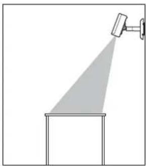
natural_image
Simple line drawing of a spotlight beam projecting onto a rectangular base (no text or symbols)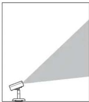
natural_image
Simple line drawing of a projector with a triangular light source, no text or symbols present安全使用須知
natural_image
Technical line drawings of three mechanical components: a bracket, a cylindrical device with mounting holes, and a separate bracket (no text or symbols present)投影機板 支臂單元 纜線夾
natural_image
Technical line drawings of two metal bracket components (no text or symbols)natural_image
Technical line drawings of two mechanical components: a bracket and a curved housing (no text or symbols)安装座外盖A安装座外盖B
natural_image
Simple line drawing of a chain link with a U-shaped loop, enclosed in a dashed border (no text or symbols)natural_image
Two identical L-shaped metal tools or connectors, shown side by side with no text or symbols.六角扳手(M4球點) 六角扳手(M6)
natural_image
Technical line drawing of a robotic device with blue and white components (no text or symbols)需要投影機板 不需要投影機板
natural_image
Line drawing of a mechanical device with a cylindrical top and base (no text or symbols)1
將投影機板放在投影機底座上。
natural_image
Technical line drawing of a computer monitor case with visible internal components and mounting points (no text or symbols)natural_image
Technical line drawing of a computer monitor chassis with mounting points (no text or symbols)安裝支臂單元
拉直支臂單元並鎖緊螺絲。
natural_image
Technical line drawing showing a mechanical assembly before and after transformation (no text or symbols)2 將支臂單元放在投影機上。
natural_image
Technical line drawing of a mechanical device with a blue lever and control panel (no text or symbols)有投影機板 無投影機板
natural_image
Technical line drawing of a blue industrial control device with a vertical cylindrical component mounted on a base (no text or symbols visible)3
natural_image
Technical line drawing of a mechanical device with labeled components (no text or symbols)有投影機板 無投影機板
natural_image
Technical line drawing of a mechanical device with a cylindrical component and mounting base (no text or symbols)
安裝安全線路
natural_image
Simple diagram of a rectangular plate with two circular holes and four evenly spaced dots (no text or symbols)2
natural_image
Pure electrical circuit lines without any symbolsnatural_image
Technical line drawing of a metal bracket component (no text or symbols)natural_image
3D diagram of a blue plastic mechanical housing with cutouts and mounting holes, showing internal components and a blue arrow indicating direction (no text or symbols)natural_image
Technical line drawing of a mechanical housing component with mounting holes and internal slots (no text or symbols)將支臂單元安裝至天花板吊架/落地架板
natural_image
Technical line drawing of a mechanical assembly with a blue component and mounting bracket (no text or symbols)natural_image
Technical line drawing of a mechanical assembly with a blue arrow indicating direction (no text or symbols)natural_image
Technical line drawing of a mechanical assembly with mounting holes and a central component (no text or symbols)
連接纜線
將必要的纜線連接至投影機的連接埠。
natural_image
Technical line drawing of a mechanical assembly with a vertical support and mounting bracket (no text or symbols)
natural_image
Technical diagram of a mechanical assembly with blue component and wiring (no text or symbols)
natural_image
Technical line drawing of a mechanical assembly with no visible text or symbols
注意
natural_image
Technical diagram of a mechanical assembly with blue components and wires, no visible text or symbols5
natural_image
Technical line drawing of a satellite dish antenna with attached cable and base, shown in two views (no text or symbols)
調整投影機的方向
natural_image
Diagram of a mechanical device with rotating arrows indicating rotational motion (no text or symbols)按投影機或遙控器上的電源按鈕。
投影機隨即開啟。

注意
開啟投影機前,請確定安裝座已牢牢固定。
natural_image
Technical line drawing of a mechanical device with a handle and gear mechanism (no text or symbols)2 調整投影機的方向。
調整方向時,請務必從下方支撐投影機。
natural_image
Technical line drawing of a mechanical device with a lever and mesh grille (no text or symbols)
©SEIKO EPSON CORPORATION 2019. All rights reserved.
ELPMB60
설치 가이드

natural_image
Technical line drawing of a mechanical assembly with mounting base and cylindrical component (no text or symbols)
안전 지침
natural_image
Technical line drawings of three mechanical components: a bracket, a cylindrical device with a knob, and a small bracket (no text or symbols present)natural_image
Technical line drawing of a mechanical housing or bracket (no text or symbols)
natural_image
Isometric line drawing of a mechanical component with cutouts and mounting holes (no text or symbols)natural_image
Technical line drawing of a mechanical component (no text or symbols)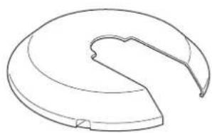
natural_image
Line drawing of a curved mechanical component or housing (no text or symbols)마운트 커버 A 마운트 커버 B
natural_image
Simple line drawing of a chain link with a loop, enclosed in a dashed border (no text or symbols)natural_image
Technical line drawing of a mechanical device with blue components and a cylindrical top (no text or symbols)
natural_image
Line drawing of a mechanical device with a vertical cylindrical component mounted on a base (no text or symbols visible)natural_image
Technical line drawing of a device casing with blue plastic cover and mounting feet (no text or symbols)natural_image
Technical line drawing of a computer chassis with mounting holes and ventilation slots (no text or symbols)암 유닛 부착하기
natural_image
Technical line drawing showing a mechanical assembly before and after transformation (no text or symbols)2
암 유닛을 프로젝터에 올려놓습니다.
natural_image
Technical line drawing of a mechanical device with a blue lever and base plate (no text or symbols)
natural_image
Technical line drawing of a blue industrial control device with a vertical cylindrical component mounted on a base (no text or symbols visible)natural_image
Technical line drawing of a mechanical device with labeled components (no text or symbols)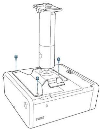
natural_image
Technical line drawing of a mechanical device with a cylindrical component and mounting base (no text or symbols)natural_image
Simple diagram of a device with two circular buttons and four dots, no text or symbols present.2
natural_image
Simple diagram of a rectangular panel with four circular holes and an oval top, no text or symbols present.natural_image
Technical line drawing of a metal bracket with mounting holes and cutouts (no text or symbols)natural_image
3D diagram of a blue plastic mechanical housing with internal compartments and mounting holes, showing a blue arrow pointing to a component (no text or symbols present)natural_image
Technical line drawing of a mechanical housing component with multiple ports and mounting holes (no text or symbols)natural_image
Technical line drawing of a mechanical assembly with a blue component and directional arrow (no text or symbols)natural_image
Technical line drawing of a mechanical assembly with a blue arrow indicating rotation (no text or symbols)natural_image
Technical line drawing of a mechanical assembly with mounting holes and a central shaft (no text or symbols)
케이블 연결하기
natural_image
Technical line drawing of a mechanical assembly with a blue arrow indicating a component (no text or symbols present)
natural_image
Technical diagram of a mechanical assembly with blue component and wiring (no text or symbols)
natural_image
Technical line drawing of a mechanical assembly with wires and components (no text or symbols)
주의
natural_image
Technical diagram of a mechanical assembly with blue components and wiring (no text or symbols)
natural_image
Technical line drawing of a satellite dish antenna with attached cable and base, shown in two views (no text or symbols)
프로젝터의 방향 조정하기
natural_image
Diagram of a mechanical device with rotating arrows indicating rotational motion (no text or symbols)natural_image
Technical line drawing of a mechanical device with a lever and adjustment knob (no text or symbols)프로젝터의 방향을 조정합니다.
natural_image
Technical line drawing of a mechanical device with a lever and adjustment knob (no text or symbols)
©SEIKO EPSON CORPORATION 2019. All rights reserved.
ELPMB60
設置工事說明書

natural_image
Technical line drawing of a mechanical assembly with mounting base and cylindrical component (no text or symbols)
安全上のご注意
natural_image
Simple line drawing of a spotlight beam projecting onto a wall (no text or symbols)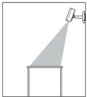
natural_image
Simple line drawing of a spray gun with a spotlight and a rectangular base (no text or symbols)
natural_image
Simple line drawing of a projector with a triangular light source, no text or symbols present安全に関する表示
natural_image
Technical line drawing of a mechanical bracket or housing (no text or symbols)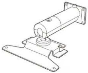
natural_image
Technical line drawing of a mechanical assembly with mounting flanges and a central shaft (no text or symbols)
natural_image
Technical line drawing of a mechanical housing or bracket (no text or symbols)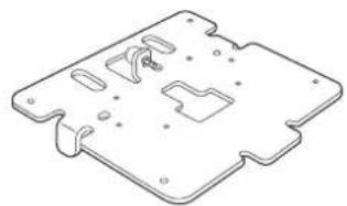
natural_image
Isometric line drawing of a mechanical component with cutouts and mounting holes (no text or symbols)natural_image
Technical line drawing of a mechanical component (no text or symbols)
natural_image
Simple line drawing of a curved mechanical component or bracket (no text or symbols)金具カバーA 金具カバーB
natural_image
Simple line drawing of two interlocked cable links with connectors (no text or symbols)
natural_image
Technical line drawing of a robotic device with blue and white components (no text or symbols)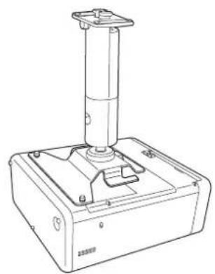
natural_image
Line drawing of a mechanical device with a vertical cylindrical component mounted on a base (no text or symbols visible)natural_image
Technical line drawing of a computer monitor case with blue plastic casing and ventilation slots (no text or symbols)natural_image
Technical line drawing of a computer chassis with mounting holes and ventilation slots (no text or symbols)アームユニットを取り付ける
natural_image
Technical line drawing of a mechanical assembly before and after transformation (no text or symbols)
natural_image
Technical line drawing of a mechanical device with a blue lever and base mount (no text or symbols)
natural_image
Technical line drawing of a blue industrial control device with a vertical cylindrical component mounted on a base (no text or symbols visible)natural_image
Technical line drawing of a mechanical device with mounting holes and a cylindrical component (no text or symbols)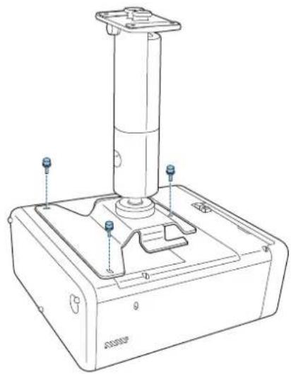
natural_image
Technical line drawing of a mechanical device with a cylindrical component and mounting base (no text or symbols)natural_image
Simple diagram of a device with two circular buttons and four dots, no text or symbols present.2
natural_image
Simple diagram of a rectangular panel with six circular holes and an oval connector (no text or symbols)natural_image
Technical line drawing of a metal bracket component (no text or symbols)natural_image
3D diagram of a blue plastic mechanical housing with mounting holes and internal compartments, showing a blue arrow pointing to a component (no text or symbols present)natural_image
Technical line drawing of a mechanical housing component with blue connectors and mounting holes (no text or symbols)natural_image
Technical illustration of a mechanical assembly with a blue component and a directional arrow (no text or symbols)natural_image
Technical line drawing of a mechanical assembly with a blue arrow indicating a component (no text or symbols present)natural_image
Technical line drawing of a mechanical component with mounting holes and a central shaft (no text or symbols)
ケーブル類を接続する
natural_image
Technical line drawing of a mechanical assembly with a blue connector and mounting bracket (no text or symbols)
natural_image
Technical diagram of a mechanical assembly with blue component and wiring (no text or symbols)
natural_image
Technical line drawing of a mechanical assembly with no visible text or symbols
注意
natural_image
Technical diagram of a mechanical assembly with blue components and wires, no visible text or symbols
natural_image
Technical line drawing of a satellite dish antenna with attached cable and base, shown in two views (no text or symbols)
プロジェクターの向きを調整する
natural_image
Diagram of a mechanical device with rotating arrows indicating rotational motion (no text or symbols)1
natural_image
Technical line drawing of a mechanical device with a lever and wheel assembly (no text or symbols)3
プロジェクターの向きを調整する。
natural_image
Technical line drawing of a mechanical device with a lever and adjustment knob (no text or symbols)
©SEIKO EPSON CORPORATION 2019. All rights reserved.