MZ372 - Mixer TASCAM - Free user manual and instructions
Find the device manual for free MZ372 TASCAM in PDF.

| Product type | Mixing console |
| Brand | Tascam |
| Model | MZ372 |
| Category | 3U rack-mountable mixing console |
| Number of input channels | 6 channels (XLR/jack) + 1 main mic input (XLR/jack) |
| Inputs | 6 mic/line inputs (balanced XLR), 6 line inputs (RCA), main mic input (XLR/jack), phono inputs (channels 2-4) |
| Outputs | 2 unbalanced main outputs (RCA), 2 balanced main outputs (XLR), sub output (RCA), monitor output (RCA), headphone output (6.35 mm jack) |
| Equalizer | 3-band (HIGH/MID/LOW) on each input channel, 2-band (HIGH/LOW) on main mic input |
| Special features | Talkover, pre-fader listen (PFL), headphone L/R split, source selection (A/B/C/MIC), output attenuator (-6 dB) |
| Power supply | External AC adapter PS-M1524, input 100-240 V~ 50/60 Hz, output 15 V DC 2.4 A |
| Power consumption | 35 W |
| Weight | 3.2 kg |
| Dimensions (rack mount) | 3U height, 19-inch standard width |
| Operating temperature range | 5 °C to 35 °C |
| Cleaning | Dry, soft cloth, avoid chemicals |
| Safety | Do not expose to water or moisture, use only the supplied adapter, have repairs done by a professional |
| Spare parts / Repairability | No user-serviceable parts, contact TASCAM support |
| Included accessories | PS-M1524 AC adapter, power cords (2 types), rack-mount screw kit, instruction manual |
| Warranty | Legal warranty according to country of purchase |
Frequently Asked Questions - MZ372 TASCAM
User questions about MZ372 TASCAM
0 question about this device. Answer the ones you know or ask your own.
Ask a new question about this device
Download the instructions for your Mixer in PDF format for free! Find your manual MZ372 - TASCAM and take your electronic device back in hand. On this page are published all the documents necessary for the use of your device. MZ372 by TASCAM.
USER MANUAL MZ372 TASCAM
OWNER'S MANUAL
ENGLISH
MODE D'EMPLOI
FRANÇAIS
MANUAL DEL USUARIO
ESPAÑOL
BEDIENUNGSANLEITUNG
DEUTSCH
• TASCAM is a trademark of TEAC CORPORATION, registered in the U.S. and other countries.
- Other company names, product names and logos in this document are the trademarks or registered trademarks of their respective owners.
ティアック株式会社
1834 Gage Road, Montebello, California 90640 USA
TEAC UK Ltd.
http://tascam.eu/
Phone: +44-8451-302511
2 Huxley Road, Surrey Research Park Guildford,
GU2 7RE, United Kingdom
TEAC EUROPE GmbH
http://tascam.eu/
Phone: +49-611-71580
Room 817, Block A, Hailrun Complex, 6021 Shennan Blvd., Futian District, Shenzhen 518040, China
IMPORTANT SAFETY PRECAUTIONS
 | CAUTIONRISK OF ELECTRIC SHOCKDO NOT OPEN | [IMAGE] | CAUTION: TO REDUCE THE RISK OF ELECTRIC SHOCK, DO NOT REMOVE COVER (OR BACK). NO USER-SERVICEABLE PARTS INSIDE. REFER SERVICING TO QUALIFIED SERVICE PERSONNEL. |
 | The lightning flash with arrowhead symbol, within equilateral triangle, is intended to alert the user to the presence of uninsulated “dangerous voltage” within the product’s enclosure that may be of sufficient magnitude to constitute a risk of electric shock to persons. | ||
 | The exclamation point within an equilateral triangle is intended to alert the user to the presence of important operating and maintenance (servicing) instructions in the literature accompanying the appliance. |
WARNING: TO PREVENT FIRE OR SHOCK HAZ-ARD, DO NOT EXPOSE THIS APPLIANCE TO RAIN OR MOISTURE.
For U.S.A.
Declaration of Conformity
Model Number: MZ-372
Trade Name: TASCAM
Responsible party: TEAC AMERICA, INC.
Address: 1834 Gage Road, Montebello, California, U.S.A.
Telephone number: 1-323-726-0303
This device complies with Part 15 of the FCC Rules. Operation is subject to the following two conditions: (1) this device may not cause harmful interference, and (2) this device must accept any interference received, including interference that may cause undesired operation.
INFORMATION TO THE USER
This equipment has been tested and found to comply with the limits for a Class B digital device, pursuant to Part 15 of the FCC Rules. These limits are designed to provide reasonable protection against harmful interference in a residential installation. This equipment generates, uses, and can radiate radio frequency energy and, if not installed and used in accordance with the instruction manual, may cause harmful interference to radio communications. However, there is no guarantee that interference will not occur in a particular installation. If this equipment does cause harmful interference to radio or television reception, which can be determined by turning the equipment off and on, the user is encouraged to try to correct the interference by one or more of the following measures.
a) Reorient or relocate the receiving antenna.
b) Increase the separation between the equipment and receiver.
c) Connect the equipment into an outlet on a circuit different from that to which the receiver is connected.
d) Consult the dealer or an experienced radio/TV technician for help.
CAUTION
Changes or modifications to this equipment not expressly approved by TEAC CORPORATION for compliance could void the user's authority to operate this equipment.
IN USA/CANADA, USE ONLY ON 120 V SUPPLY.
For Canada
THIS CLASS B DIGITAL APPARATUS COMPLIES WITH CANADIAN ICES-003.
CET APPAREIL NUMERIQUE DE LA CLASSE B EST CONFORME A LA NORME NMB-003 DU CANADA.

This product complies with the European Directives request and the other Commission Regulations.
CE Marking Information
EN55103-2
a) Applicable electromagnetic environment: E1, E2 E3, E4
IMPORTANT SAFETY INSTRUCTIONS
-
Read these instructions.
-
Keep these instructions.
-
Heed all warnings.
-
Follow all instructions.
-
Do not use this apparatus near water.
-
Clean only with dry cloth.
-
Do not block any ventilation openings. Install in accordance with the manufacturer's instructions.
-
Do not install near any heat sources such as radiators, heat registers, stoves, or other apparatus (including amplifiers) that produce heat.
-
Do not defeat the safety purpose of the polarized or grounding-type plug. A polarized plug has two blades with one wider than the other. A grounding type plug has two blades and a third grounding prong. The wide blade or the third prong are provided for your safety. If the provided plug does not fit into your outlet, consult an electrician for replacement of the obsolete outlet.
-
Protect the power cord from being walked on or pinched particularly at plugs, convenience receptacles, and the point where they exit from the apparatus.
-
Only use attachments/accessories specified by the manufacturer.
-
Use only with the cart, stand, tripod, bracket, or table specified by the manufacturer, or sold with the apparatus. When a cart is used, use caution when moving the cart/apparatus combination to avoid injury from tip-over.

natural_image
Symbolic icon of a person using a large scale inside a circle with no text or symbols-
Unplug this apparatus during lightning storms or when unused for long periods of time.
-
Refer all servicing to qualified service personnel. Servicing is required when the apparatus has been damaged in any way, such as power-supply cord or plug is damaged, liquid has been spilled or objects have fallen into the apparatus, the apparatus has been exposed to rain or moisture, does not operate normally, or has been dropped.
● The mains plug is used as the disconnect device, the disconnect device shall remain readily operable.
- Caution should be taken when using earphones or headphones with the product because excessive sound pressure (volume) from earphones or headphones can cause hearing loss.
- If you are experiencing problems with this product, contact TEAC for a service referral. Do not use the product until it has been repaired.
- Do not remove the external cases or cabinets to expose the electronics. No user serviceable parts are inside.
- If you are experiencing problems with this product, contact the store where you purchased the unit for a service referral. Do not use the product until it has been repaired.
- Use of controls or adjustments or performance of procedures other than those specified herein may result in hazardous radiation exposure.
CAUTION
- Do not expose this apparatus to drips or splashes.
- Do not place any objects filled with liquids, such as vases, on the apparatus.
- Do not install this apparatus in a confined space such as a book case or similar unit.
● The apparatus should be located close enough to the AC outlet so that you can easily grasp the power cord plug at any time.
- If the product uses batteries (including a battery pack or installed batteries), they should not be exposed to sunshine, fire or excessive heat.
- CAUTION for products that use replaceable lithium batteries: there is danger of explosion if a battery is replaced with an incorrect type of battery. Replace only with the same or equivalent type.
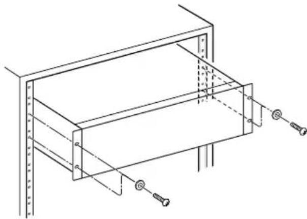
RACK-MOUNTING THE UNIT
Use the supplied rack-mounting kit to mount the unit in a standard 19-inch rack, as shown below.
natural_image
Technical line drawing of a mechanical assembly with mounting holes and structural supports (no text or symbols)CAUTION
- Leave 1U of space above the unit for ventilation.
- Allow at least 10 cm (4 in) at the rear of the unit for ventilation.
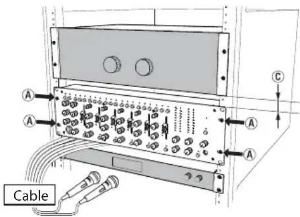
Rack-mounting using the universal holes
To use the universal holes of this unit to mount it in a rack, install it with the rackmount screw kit as shown in the illustrations below.
Universal Hole position
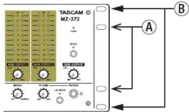
Installation in a 4U space
Use the Ⓐ holes to mount the unit in the rack.
Installing this way creates gaps above and below the MZ-372 (©).
These gaps can be used to route cables connected to the back of the unit, for example.
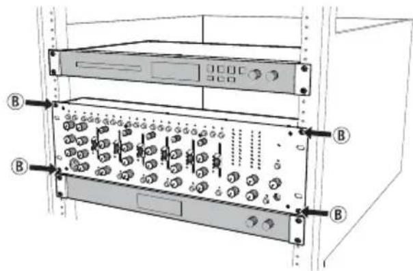
Installation in a 3U or larger space
Use the Ⓑ holes to mount the unit in the rack.
For European Customers
Disposal of electrical and electronic equipment
(a) All electrical and electronic equipment should be disposed of separately from the municipal waste stream via designated collection facilities appointed by the government or the local authorities.
(b) By disposing of the electrical and electronic equipment correctly, you will help save valuable resources and prevent any potential negative effects on human health and the environment.
(c) Improper disposal of waste equipment can have serious effects on the environment and human health as a result of the presence of hazardous substances in electrical and electronic equipment.
(d) The crossed out wheeled dust bin symbol indicates that electrical and electronic equipment must be collected and disposed of separately from household waste.
(e) The return and collection systems are available to the end users. For more detailed information about disposal of old electrical and electronic equipment, please contact your city office, waste disposal service or the shop where you purchased the equipment.

For China

IMPORTANT SAFETY INSTRUCTIONS .... 4
Features....7
Items included with this product .... 7
Conventions used in this manual 8
Precautions for placement and use......8
Beware of condensation 8
Cleaning the unit 8
Using the TEAC Global Site 8
Product registration....8
About TASCAM customer support service......8
Names and functions of parts 9
Front panel 9
Rear panel....10
Preparation 11
Connecting the power 11
Attaching the cord....11
Connecting other equipment.... 12
Turning the power on and off.... 13
Operation procedures....14
Adjusting mic input channels (1-6).... 14
Adjusting line input channels (1-6) 14
Adjusting the input of a mic connected to the MAIN MIC INPUT jack....14
Output channels....14
Using the talkover function....15
Listening to channel pre-fader signals....15
Troubleshooting 15
Specifications....16
Audio inputs....16
Audio outputs 16
Audio performance 16
General....17
Dimensional drawings.... 17
Block diagram....18
Thank you very much for purchasing the TASCAM MZ-372.
Before using this unit, read this Owner's Manual carefully so that you will be able to use it correctly and enjoy working with it for many years. After you have finished reading this manual, please keep it in a safe place for future reference.
You can also download this Owner's Manual from the TEAC Global Site (http://teac-global.com/).
Features
- Rackmount mixer with numerous input channels and two pairs of main outputs
- Six input channels are equipped with gain controls, LED level meters, three-band equalizers and faders Mic or line input can be easily selected with switches
● Independent front mic input with volume control and two-band equalizer
● Talkover function automatically lowers background music volume according to mic volume
● Two main outputs with stereo LED level meters
- Sub output with volume control and mono/stereo output format selection
● Headphone output with volume control can be used for pre-fader monitoring of selected input channels and the main output
● 3U rackmount size
Items included with this product
This product includes the following items.
Take care when opening the package to avoid damaging the items. Keep the packing materials for transportation in the future.
Please contact the store where you purchased this unit if any of these items are missing or have been damaged during transportation.
● Main unit....×1
● AC adapter (TASCAM PS-M1524)....× 1
● Cord for AC adapter (JAPAN USA/EUROPE).....×2
- Rackmount screw kit....x 1
- Owner's Manual (this document) including warranty....×1
CAUTION
Always use the included AC adapter (TASCAM PS-M1524) when using this unit. Never use the included AC adapter with any other device. Doing so could cause damage, fire or electric shock.
Conventions used in this manual
In this manual, we use the following conventions:
● The names of switches, connectors and other physical parts of this unit are written using a bold font like this: POWER switch.
● Additional information is provided as necessary as tips, notes and cautions.
TIP
These are tips about how to use the unit.
NOTE
These provide additional explanations and describe special cases.
CAUTION
Failure to follow these instructions could result in injury, damage to equipment or lost recording data, for example.
Precautions for placement and use
● The operating temperature range of this unit is 5–35 °C.
- Do not install this unit in the following types of locations. Doing so could cause malfunction.
Places with significant vibrations
Near windows or other places exposed to direct sunlight
Near heaters or other extremely hot places
Extremely cold places
Places with bad ventilation or high humidity
Very dusty locations
● To enable good heat dissipation, do not place anything on top of the unit.
- Do not place the unit on top of a power amplifier or other device that generates heat.
Beware of condensation
If the unit is moved from a cold to a warm place, or used after a sudden temperature change, there is a danger of condensation; vapor in the air could condense on the internal mechanism, making correct operation impossible.
To prevent this, or if this occurs, let the unit sit for one or two hours at the new room temperature before using it.
Cleaning the unit
To clean the unit, wipe it gently with a soft dry cloth. Do not wipe with chemical cleaning cloths, benzene, thinner, alcohol or other chemical agents. Doing so could damage the surface or cause discoloration.
Using the TEAC Global Site
You can download updates for this unit from the TEAC Global Site:
http://teac-global.com/
In the TASCAM Downloads section, select the desired language to open the Downloads website page for that language.
Product registration
Customers in the USA, please visit the following TASCAM website to register your TASCAM product online.
http://tascam.com/
About TASCAM customer support service
TASCAM products are supported and warranted only in their country/region of purchase.
To receive support after purchase, on the TASCAM Distributors list page of the TEAC Global Site (http://teac-global.com/), search for the local company or representative for the region where you purchased the product and contact that organization.
When making inquiries, the address (URL) of the shop or web shop where it was purchased and the purchase date are required.
Moreover, the warranty card and proof of purchase might also be necessary.
Front panel
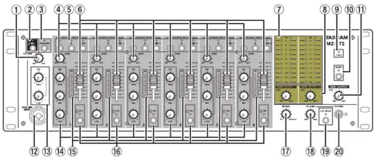
① MAIN MIC INPUT VOLUME knob
Use to adjust the mic input level from the MAIN MIC INPUT jack (12).
② MAIN MIC switch and indicator
Press to turn mic input from the MAIN MIC INPUT jack (12) on/off.
The MIC indicator lights when mic input is on.
③ TALKOVER switch/indicator
Press to turn the talkover function on/off.
When the talkover function is on, the TALKOVER indicator lights, and the levels of all input channels are lowered automatically when sound is input from a mic connected to the MAIN MIC INPUT.
④ GAIN knobs
Use these to adjust the levels of each input channel.
⑤ SOURCE SELECT switches/indicators
Use these to set the input source to the C (MONO) /MIC (26) or LINE A/B (34) input jacks on the back of the unit.
The indicator for the selected input lights.
⑥ Channel faders
Use these to adjust the send levels of channel signals.
⑦ Output level indicators
These indicators show the output levels of the MAIN OUTPUTS 1-2 (UNBALANCED) (24) jacks and MAIN OUTPUTS 1-2 (BALANCED) (33) jacks on the back of the unit.
⑧ MAIN OUTPUT VOL knobs
These adjust the output levels of the MAIN OUTPUTS 1-2 (UNBALANCED) (24) and MAIN OUTPUTS 1-2 (BALANCED) (33) jacks on the back of the unit.
⑨ POWER indicator
This shows the status of the unit.
When the POWER (21) switch on the back of the unit is on, the POWER indicator lights.
⑩ MONO switch/indicator
When the MONO switch is on (MONO indicator lit), mono signals will be output from the stereo output buses (MAIN OUTPUT 1/2, SUB OUTPUT, MONITOR OUT).
⑪ SUB OUTPUT VOL knob
Use to adjust the output level of the SUB OUTPUT jacks (32) on the back of the unit.
⑫ MAIN MIC INPUT jack
This is an XLR/TRS combo jack for mic input.
Use the MAIN MIC INPUT VOLUME knob (①) to set the input level.
⑬ MAIN MIC INPUT EQ knobs
This is a 2-band equalizer (HIGH/LOW) for the mic input sound.
⑭ INPUTS EQ knobs
Use this 3-band equalizer (HIGH/MID/LOW) to adjust the sound from the C (MONO) /MIC (26) input jack or LINE A or B (34) input jacks on the back of the unit.
⑮ Channel level meters
These indicators show the input levels of input channels.
⑯ PFL switches/indicators
- When a PFL switch is on (PFL indicator lit), the pre-fader signal (signal before fader adjustment) can be monitored through headphones.
- When a PFL switch is off, only the normal monitoring sound is output.
⑰ MIXING knob
Use this to mix the pre-fader and monitoring signals output to the headphones.
- Turn all the way to the PFL side to monitor channels that have their PFL (16) switches pressed in.
- Turn all the way to the MONITOR side to monitor the monitoring signal.
⑱ PHONES VOLUME knob
Use this to adjust the headphone output level.
⑲ L/R SPLIT switch/indicator
Press to change the headphone output mode.
- When the L/R SPLIT switch is on (indicator lit), pre-fader signals are output from the left channel and the monitoring signal is output from the right channel.
- When the L/R SPLIT switch is off (indicator un-lit), the monitoring signal is output. When PFL switches are on, the pre-fader and monitoring signals are mixed and output together.
NO
The PFL signals are mixed with the monitoring signal, so the selected PFL signals will sound louder.
⑳ PHONES jack
Use this standard stereo jack to connect stereo headphones.
Use an adapter to connect headphones with a mini plug.
The monitoring and PFL signals can be monitored, depending on the PFL (16) and L/R SPLIT (19) switch settings.
Rear panel
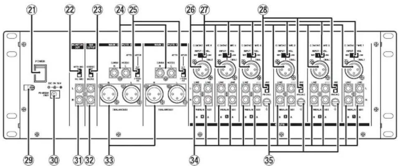
②1 POWER switch
Press to turn the unit on and off.
When on, the POWER (⑨) indicator lights on the front of the unit.
⑳ MONITOR OUT mic mix switch
This sets whether or not the input signal from a mic connected to the MAIN MIC INPUT (12) jack on the front of the unit is sent to and mixed with the monitoring output.
To mix the input signal from a mic connected to the MAIN MIC INPUT (12) jack with the monitoring output, set the MONITOR OUT mic mix switch to WITH MIC.
②3 SUB OUTPUT switch
Set whether the output from the SUB OUTPUT (32) jacks is stereo or mono.
Set it to MONO for mono output.
⑳ MAIN OUTPUTS 1-2 (UNBALANCED) jacks
These analog outputs are RCA pin jacks.
Use the ATTENUATOR (25) switch to change the output level.
⑲ ATTENUATOR switches
These switch the output levels from the MAIN OUTPUTS 1-2 (UNBALANCED) (24) and MAIN OUTPUTS 1-2 (BALANCED) (33) jacks.
Set them to OFF if the destination amplifier receives high gain, and set it to ON (-6dB) if the destination amplifier receives low gain.
②6 C (MONO) /MIC input jacks
These are analog XLR input jacks (1: GND, 2: HOT, 3: COLD).
Their input gains can be adjusted using the GAIN (④) knobs on the front of the unit.
⑳ INPUT LEVEL switches
Use these to set the input levels of the input sources (mic or line) connected to the C (MONO) /MIC (26) input jacks.
Set to MIC for mic level signals, and set to LINE for line level signals.
⑳ LINE/PHONO input selection switches
For channels 2–4, if the output of a CD player or similar device is connected to a LINE A input (34) jack, set this to LINE. If a record player output is connected, set it to PHONO.
⑲ Cord holder
Attach the power cord of the included AC adapter (TASCAM PS-M1524) here to prevent accidental disconnection. (See "Attaching the cord" on page 11.)
③0 DC IN 15V connector
Connect the included AC adapter (TASCAM PS-M1524) here.
③1 MONITOR OUT jacks
These RCA pin jacks are analog monitoring outputs.
③2 SUB OUTPUT jacks
These RCA pin jacks are analog outputs.
Mono signals will be output if the SUB OUTPUT (23) switch is set to MONO.
③3 MAIN OUTPUTS 1-2 (BALANCED) jacks
These analog outputs are XLR jacks. (1: GND, 2: HOT, 3: COLD)
Use the ATTENUATOR (25) switches to change the output levels.
③4 LINE A/B input jacks
These RCA pin jacks are analog line outputs.
Record players can be connected to the LINE A input jacks of channels 2–4. When connecting a record player to these jacks, also connect its grounding wire to the ± (GND) jack (35), and set the LINE/PHONO input selection switch (28) to PHONO.
③5 ± (GND) connectors
If a record player is connected to the LINE A input (34) jacks of channel 2–4, also connect its grounding wire to this.
NOTE
If a humming noise occurs when connecting a device other than a record player, connecting a grounding wire from the metal frame of that device (or the rack frame if rackmounted) to this could reduce the noise.
Preparation
Connecting the power
Use the included AC adapter (TASCAM PS-M1524) to connect a power supply to the unit as shown below.

CAUTION
Always use the AC adapter (TASCAM PS-M1524) that was packaged with the unit. Using a different AC adapter could cause malfunction, overheating, fire or other problems.
NOTE
The AC adapter for the unit includes two types of adapter cords. Attach the type of AC adapter cord that matches the power outlet that you are using.
Attaching the cord
In order to prevent the cord from becoming disconnected during use, attach it to the cord holder (29) when connecting it to the unit.
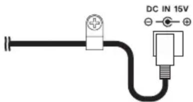
- Remove the cord holder (29) screw.
- Place the cord in the cord holder (29).
- Tighten the cord holder (29) screw.
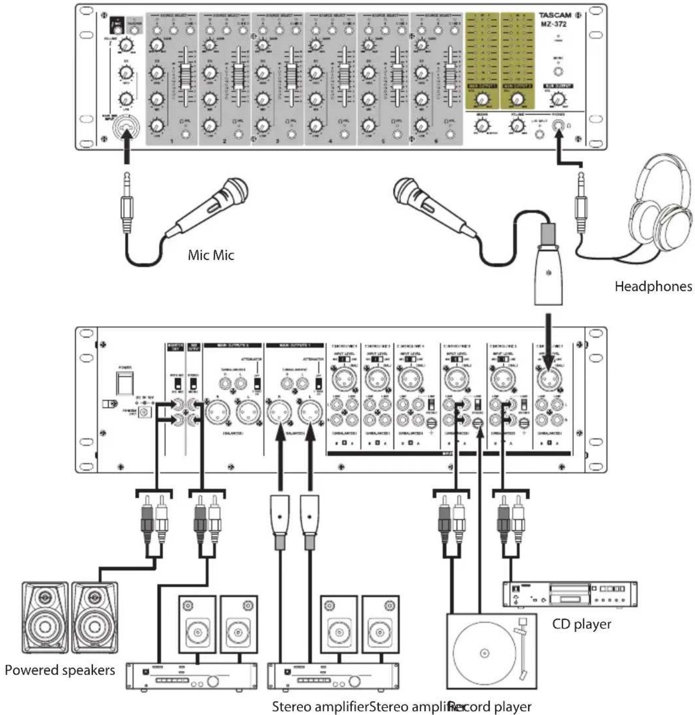
Connecting other equipment
This is an example of MZ-372 connections.
Precautions before making connections
● Carefully read the operation manuals of the devices to be connected and then connect them correctly.
● Before making connections, turn this unit and all equipment to be connected off (standby).
● Install all connected devices, including this unit, so that they are powered from the same line. When using a power strip or similar device, be sure to use one that has high current capacity (thick cable) in order to minimize fluctuations in power voltage.
- When connecting audio devices, minimize the channel 1–6 GAIN (④) knobs and faders (⑥), and the MAIN OUTPUT VOL (⑧), SUB OUTPUT VOL (⑪) and PHONES VOLUME (⑯) knobs. Failure to do so could cause sudden loud noises from monitoring equipment, and this could damage the equipment or harm hearing.
Examples of connections to an MZ-372
Connecting microphones
Mics can be connected to the MAIN MIC INPUT (12) jack on the front of the unit or to one of the channel 1-6 C (MONO) /MIC (26) input jacks on the back of the unit with the INPUT LEVEL (27) switch set to MIC.
Connecting electronic devices and other audio equipment
When connecting an electronic device or other audio equipment, connect it to channel 1–6 C (MONO) /MIC (26) input jacks, and set the INPUT LEVEL switch (27) to LINE. The device can be connected to channel 1–6 LINE A or B (34) input jacks.
When connected to channel 2-4 LINE A (34) input jacks, set the LINE/PHONO (28) input switch to LINE.
NOTE
The C (MONO) /MIC (26) jacks are mono inputs.
Connecting record players
When connecting a record player, connect it to channel 2–4 LINE A (34) input jacks, and set the LINE/PHONO (28) input switch to PHONO.
Connect the grounding wire from the record player to the ± (GND) (35) connector.
Connecting monitor speakers
Connect monitor speakers (powered speakers or an amplifier and speaker system) to the MONITOR OUT (31) jacks.
To mix in the mic input signal from the MAIN MIC INPUT (12) jack, and output it from the monitor speakers, set the MONITOR OUT (22) mic mix switch to WITH MIC.
Connecting headphones
Connect headphones to the PHONES (20) jack (standard stereo).
You can monitor input channel pre-fader signals and the signal before it is sent to the stereo output bus.
CAUTION
Before connecting headphones, minimize the volume with the PHONES VOLUME (18) knob. Failure to do so could result in a sudden loud noise that could harm hearing, for example.
NOTE
Since the headphone sound is output from the monitoring bus, the position of the MAIN OUTPUT VOL (⑧) knob has no effect on it.
Connecting stereo amplifiers
When connecting a stereo amplifier, connect it to the MAIN OUTPUTS 1-2 (UNBALANCED) (24) or MAIN OUTPUTS 1-2 (BALANCED) (33) jacks.
TIP
- When connecting 2 or more amplifier and speaker systems, including main and sub, main and monitoring, or front and rear combinations, using the MAIN OUTPUTS 1-2 (UNBALANCED) (24), MAIN OUTPUTS 1-2 (BALANCED) (33), and SUB OUTPUT (32) jacks could be convenient. Moreover, the outputs of the jacks are independent and have their own dedicated output knobs, so you can set the output levels separately with this unit.
- By connecting a recorder to MONITOR OUT (31) jacks, the signal output to amplifier/speaker systems can be recorded.
Turning the power on and off
CAUTION
- Turn down the volume of the sound system connected to the unit before starting up or shutting down the unit.
- Do not wear connected headphones when turning the unit on and off. Loud noises could damage the speakers or harm your hearing.
Before turning the power on
- Make the following settings on the front of the unit.
• EQ knobs → center values
- Other knobs → all the way left (MIN side)
- Faders → all the way down
- Switches → off (not pushed in)
- Minimize the output levels of audio sources and input levels of amplifiers connected to this unit.
Turning the power on
- Use the POWER (21) switch on the back of the unit to turn its power on.
The POWER (⑨) indicator on the front of the unit will light when on.
- Turn connected input audio source devices on.
- Finally turn amplifiers on.
Turning the power off
Follow the procedures above in reverse when turning the power off.
Failure to follow the correct order could result in clicking noises, for example, that might damage equipment.
Operation procedures
After turning the power on, adjust the levels of the input signals.
Adjusting mic input channels (1-6)
- Set the channel 1–6 GAIN (④) and EQ (⑭) knobs to their center values.
- Press the channel 1–6 SOURCE SELECT (⑤) C/MIC switches so the C/MIC indicators (②) light.
- When connecting a mic to a channel 1–6 C (MONO) /MIC (26) input jack, set the INPUT LEVEL switch (27) to MIC.
- Set the MAIN OUTPUT VOL (⑧) knob levels low.
- Try speaking into the mic. Use the channel 1–6 GAIN (④) knob to adjust the input level so that its level meter (⑮) lights around 0 dB.
- Use the channel 1–6 EQ (14) knobs to adjust the equalizer.
- Follow the above procedures for other input channels with connected mics.
Adjusting line input channels (1-6)
- Set the channel 1–6 GAIN (④) and EQ (⑭) knobs to their center values.
- When connecting an audio device to channel 1–6, press the SOURCE SELECT switch (⑤), so that the SOURCE SELECT indicator (A/B/C/MIC) lights.
- When connecting an audio device to a channel 1–6 C (MONO) /MIC (26) input jack, set the INPUT LEVEL switch (27) to LINE.
When connecting an audio device to channel 1–6 LINE A/B (v) input jacks, set the LINE/PHONE switch (28) to LINE. - Set the MAIN OUTPUT VOL (⑧) knob levels low.
- Start playback on the connected audio device. Use the channel 1–6 GAIN (④) knob to adjust the input level so that its level meter (⑮) lights around 0 dB.
- Use the channel 1–6 EQ (14) knobs to adjust the equalizer.
- Follow the above procedures to adjust other input channels with connected audio devices.
Adjusting the input of a mic connected to the MAIN MIC INPUT jack
- Connect a mic to the MAIN MIC INPUT jack (⑫), and press the MAIN MIC (②) switch so the MAIN MIC (②) indicator lights.
- Use the MAIN MIC INPUT VOLUME (①) knob to adjust the mic input level.
- Use the MAIN MIC INPUT EQ (13) knobs to adjust the 2-band (HIGH/LOW) equalizer for the mic sound.
Output channels
Output signals can be sent to the following jacks from the stereo output bus.
● MAIN OUTPUTS 1-2 (UNBALANCED) (24) and MAIN OUTPUTS 1-2 (BALANCED) (33) jacks
SUB OUTPUT (32) jacks
● MONITOR OUT (③1) jacks
NOTE
The output level from the MONITOR OUT (31) jacks cannot be adjusted.
Adjusting the levels output from the MAIN OUTPUTS 1-2 (UNBALANCED) and MAIN OUTPUTS 1-2 (BALANCED) jacks
While checking the output level indicators (⑦), use the channel faders (⑥) and MAIN OUTPUT VOL (⑧) knobs to adjust the output levels. The optimal output level adjustment is usually when the output level indicators (⑦) light around 0 dB.
When an amplifier is connected to the MAIN OUTPUTS 1-2 (UNBALANCED) (24) or MAIN OUTPUTS 1-2 (BALANCED) (33) jacks, set the ATTENUATOR (25) switch to OFF if it accepts high gain or ON (-6dB) if it accepts low gain.
Adjusting the level output from the SUB OUTPUT jacks
Use the SUB OUTPUT VOL (11) knob to adjust the output level.
If the MONO (10) switch is set to ON (MONO indicator lit) mono signals will be output from all output jacks.
To output mono signals from only the SUB OUTPUT (32) jacks, set the SUB OUTPUT (23) switch to MONO.
Using the talkover function
When the talkover function is turned on by pressing the TALKOVER (③) switch, the levels of channels 1–6 will be automatically lowered when sound is input from a mic connected to the MAIN MIC INPUT (⑫) jack, making the mic signal easier to hear.
To turn the talkover function off, press the TALKOVER (③) switch to turn it off (TALKOVER (③) indicator becomes unlit).
Listening to channel pre-fader signals
By pressing the PFL (16) switches of channels to turn them on, you can enable headphone monitoring of individual channels 1–6, even when their faders (6) are set at minimum values.
You can also monitor the signal before it is sent to the stereo output bus.
-
Press the PFL (16) switches for the channels you want to monitor so that their PFL indicators light, and turn the MIXING (17) knob to PFL.
To monitor the signal before it is sent to the stereo output bus, turn the MIXING (17) knob to MONITOR. -
After making mixing adjustments, use the PHONES VOLUME (18) knob to adjust the monitoring output level.
NOTE
- The L/R SPLIT (19) switch can be turned on/off to change the headphone output mode.
- When the L/R SPLIT switch (19) is on (indicator lit), the pre-fader signals are output from the left channel and the monitoring signal is output from the right channel.
- When the L/R SPLIT switch (19) is off (indicator unlit), the pre-fader signals and the monitoring signal are mixed and output together from both headphone channels.
- When the PFL (16) switch is off, if the L/R SPLIT (19) switch is set to on, the monitoring signal will be output from the right channel and no sound will be output from the left channel of the headphones.
Troubleshooting
If you are having trouble with the operation of this unit, please try the following before seeking repair. If these measures do not solve the problem, please contact the store where you purchased this unit or TASCAM customer support service.
The unit will not turn on.
- Confirm that the AC adapter (TASCAM PS-M1524) is securely connected to both the outlet and the DC jack.
Sound is not output from speakers connected via the MAIN OUTPUTS 1-2 jacks.
- Check the settings and volume of the connected amplifier.
- Confirm that channel faders (⑥) are raised.
- Confirm that the input sound source is connected properly.
The volume is low even when faders are raised.
- Confirm that the GAIN (④) knobs for channels 1–6 are set properly.
- If mics are being input on channels 1–6, confirm that the INPUT LEVEL (27) switches are set to LINE.
The sound is distorted.
- Confirm that the GAIN (④) knobs for channels 1–6 are set properly.
- Confirm that the EQ is not set too high.
- Confirm that the channel 1–6 (⑥) faders and MAIN OUTPUT VOL (⑧) knob are not set too high.
Sound from a record player is strange.
- Confirm that it is connected to channel 2–4 LINE A (34) input jacks and the LINE/PHONO (28) input switch is set to PHONO.
- Confirm that the grounding wire from the record player is connected to the ± (GND) (35) connector.
A connected device is making a humming noise.
- Connect a grounding wire from the metal frame of the connected device to the 12 (GND) (35) connector on this unit.
No sound is output from the monitoring system connected to the MONITOR OUT jacks.
- Check the settings of the connected monitoring system.
- Confirm that the channel 1–6 GAIN (④) knobs and channel faders (⑥) are raised.
Specifications
Audio inputs
MAIN MIC INPUT (BALANCED) jacks
Connectors:
XLR-3-31 (1: GND, 2: HOT, 3: COLD)
6.3mm (1/4") standard TRS jacks (Tip: HOT, Ring: COLD, Sleeve: GND)
Input impedance: 33 kΩ
Nominal input level: -65 dBu
(VOLUME knob at MAX)
Nominal input level: -30 dBu
(VOLUME knob at MIN)
INPUTS: MIC (BALANCED) jacks
Connectors: XLR-3-31 (1: GND, 2: HOT, 3: COLD)
Set to MIC
Maximum input level: -30 dBu
Minimum input level: -65 dBu
Input impedance: 33 kΩ
Set to LINE
Nominal input level: -1 dBu
Maximum input level: 20 dBu
Input impedance: 22 kΩ
INPUTS: LINE (UNBALANCED) jacks
Connectors: RCA pin jacks
Nominal input level: -10 dBV
Maximum input level: 10 dBV
Input impedance: 22 kΩ
● 0 dBu=0.775 Vrms, 0 dBV=1 V
Audio outputs
MAIN OUTPUTS (UNBALANCED) jacks
Connectors: RCA pin jacks
Rated output level: -10 dBV
Maximum output level: 6 dBV
Output impedance: 200 Ω
MAIN OUTPUTS (BALANCED) jacks
Connectors: XLR-3-32 (1: GND, 2: HOT, 3: COLD)
Rated output level: 4 dBu
Maximum output level: 24 dBu
Output impedance: 200 Ω
SUB OUTPUT connectors
Connectors: RCA pin jacks
Rated output level: -16 dBV
Maximum output level: 0 dBV
Output impedance: 200 Ω
MONITOR OUT jacks
Connectors: RCA pin jacks
Rated output level: -16 dBV
Maximum output level: 0 dBV
Output impedance: 200 Ω
PHONES jack
Connectors: 6.3mm (1/4") standard stereo jack
Maximum output: 50 mW + 50 mW
(into 32 Ω load)
● 0 dBu=0.775 Vrms, 0 dBV=1 V
Audio performance
Frequency response
20 Hz–20 kHz (INPUTS LINE to MAIN OUTPUTS)
Distortion
0.03% or less (INPUTS LINE to MAIN OUTPUTS)
S/N ratio
80 dB or more (INPUTS LINE to MAIN OUTPUTS)
Crosstalk
65 dB or more (INPUTS LINE to MAIN OUTPUTS)
General
Power
Dedicated AC adapter (TASCAM PS-M1524)
Input voltage: AC 100–240V \~, 50/60Hz
Output voltage: DC 15V
Output current: 2.4 A
Power consumption
35 W
Dimensions
482.0 × 132.0 × 93.2 mm (width × height × depth, including protrusions)
Weight
3.2 kg
Dimensional drawings
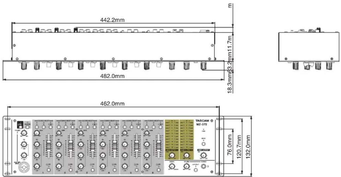
● Illustrations in this manual might differ in part from the actual product.
- Specifications and external appearance might be changed without notification to improve the product.
Block diagram
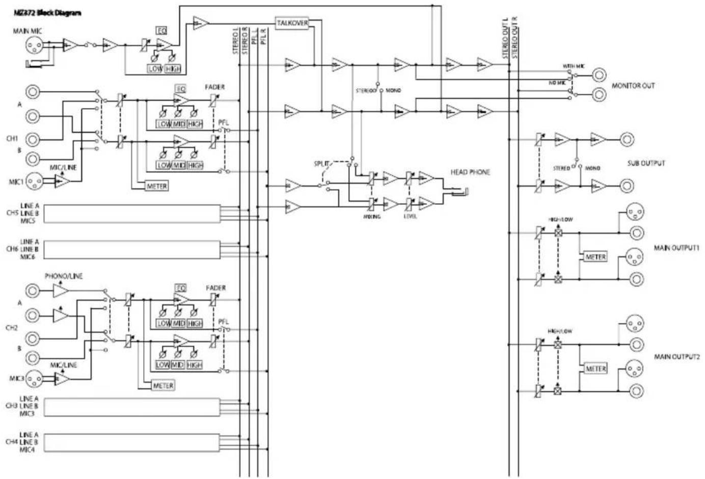
flowchart
graph TD
    subgraph "MZ372 Block Diagram"
        A["MAIN MIC"] --> B["Low High"]
        B --> C["EQ"]
        C --> D["TALKOVER"]
        D --> E["STEREO L STEREO PEL PFL R"]
        E --> F["MOND"]
        F --> G["STEREO OUT L STEREO OUT R"]
        H["A"] --> I["LOW MID HIGH"]
        J["CH1"] --> K["LOW MID HIGH"]
        L["B"] --> M["METER"]
        N["MIC1"] --> O["MINO/LINE"]
        P["LINE A CH5 LINE B MIC5"] --> Q
        R["LINE A CH6 LINE B MIC6"] --> S
        T["PHONE/LINE"] --> U["FADER"]
        V["A"] --> W["LOW MID HIGH"]
        X["CH2"] --> Y["PFL"]
        Z["B"] --> AA["LOW MID HIGH"]
        AB["MIC3"] --> AC["METER"]
        AD["LINE A CH3 LINE B MIC3"] --> AE
        AF["LINE A CH4 LINE B MIC4"] --> AG
    end

    subgraph "MOTOR Signals"
        B --> H
        I --> J
        K --> L
        M --> O
        Q --> P
        U --> V
        AA --> X
        AC --> Y
        AE --> AC
        AG --> AF
    end

    subgraph "SPLIT"
        E --> F
        F --> G
        G --> H
        H --> I
        I --> J
        J --> K
        K --> L
        L --> M
        M --> N
        N --> O
        O --> P
        P --> Q
        Q --> R
        R --> S
        S --> T
        T --> U
        U --> V
        V --> X
        X --> Y
        Y --> Z
        Z --> AA
        AA --> AB
    end

    subgraph "HEAD PHONE"
        F --> G
        G --> H
        H --> I
        I --> J
        J --> K
        K --> L
        L --> M
        M --> N
        N --> O
        O --> P
        P --> Q
        Q --> R
        R --> S
        S --> T
        T --> U
        U --> V
        V --> W
        W --> X
        X --> Y
        Y --> Z
    end

    subgraph "SUB OUTPUT"
        H --> I
        I --> J
        J --> K
        K --> L
        L --> M
        M --> N
        N --> O
        O --> P
        P --> Q
    end

    subgraph "MAIN OUTPUT1"
        H --> I
        I --> J
        J --> K
        K --> L
        L --> M
        M --> N
        N --> O
    end

    subgraph "MAIN OUTPUT2"
        H --> I
        I --> J
        J --> K
        K --> L
        L --> M
    end
PRÉCAUTIONS DE SÉCURITÉ IMPORTANTES
THIS CLASS B DIGITAL APPARATUS COMPLIES WITH CANADIAN ICES-003.
CET APPAREIL NUMÉRIQUE DE LA CLASSE B EST CONFORME À LA NORME NMB-003 DU CANADA.

natural_image
Symbolic icon of a person using a large scale inside a circle (no text or symbols)natural_image
Technical line drawing of a mechanical assembly with mounting brackets and bolts (no text or symbols)ATTENTION
① Bouton VOLUME d'entrée MAIN MIC INPUT
⑧ Boutons MAIN OUTPUT VOL
⑪ Bouton SUB OUTPUT VOL
⑯ Commutateurs/voyants PFL
⑲ Commutateur/voyant L/R SPLIT
③2 Prises SUB OUTPUT
③3 Prises MAIN OUTPUTS 1-2 (BALANCED)
● Prises MAIN OUTPUTS 1-2 (UNBALANCED) (24) et MAIN OUTPUTS 1-2 (BALANCED) (33)
● Prises SUB OUTPUT (32)
● Prises MONITOR OUT (31)
NOTE
Prises MAIN OUTPUTS (BALANCED)
482,0 × 132,0 × 93,2 mm
natural_image
Symbolic icon of a person using a ladder inside a circle with no text or symbolsnatural_image
Technical line drawing of a mechanical assembly with mounting brackets and bolts (no text or symbols)CUIDADO
① Mando MAIN MIC INPUT VOLUME
③ Interruptor/piloto TALKOVER
⑧ Mandos MAIN OUTPUT VOL
⑪ Mando SUB OUTPUT VOL
⑬ Mandos MAIN MIC INPUT EQ
②3 Interruptor SUB OUTPUT
20 Hz–20 kHz (INPUTS LINE a MAIN OUTPUTS)
Distorsión
0.03% o inferior (INPUTS LINE a MAIN OUTPUTS)
natural_image
Technical line drawing of a mechanical assembly with bolts and a rectangular frame (no text or symbols)Kondensation vermeiden
① Eingangspegelregler Hauptmikrofon (MAIN MIC INPUT VOLUME)
natural_image
Technical line drawing of a mechanical assembly with mounting holes and a rectangular frame (no text or symbols)結露について
① MAIN MIC INPUT VOLUMEつまみ
(INPUTS LINE to MAIN OUTPUTS)
歪率
80dB (INPUTS LINE to MAIN OUTPUTS)
クロストーク
< In the United States >
This warranty gives you specific legal rights and you may also have other rights which vary from state to state. This warranty is only valid within the country the unit was originally purchased.
WHAT IS AND IS NOT COVERED
Except as specified below, this warranty covers all defects in materials and workmanship in this product. The following are not covered by the warranty:
-
Damage to or deterioration of the external cabinet.
-
Damages resulting from accident, misuse, abuse or neglect.
- Damage resulting from failure to perform basic daily maintenance and/or calibration or otherwise resulting from failure to follow instructions contained in your owner's manual.
- Damage occurring during shipment of the product. (Claims must be presented to the carrier)
- Damage resulting from repair or attempted repair by anyone other than TEAC or an authorized TASCAM service station.
- Damage resulting from causes other than product defects, including lack of technical skill, competence, or experience of the user.
- Damage to any unit which has been altered or on which the serial number has been defaced, modified or is missing.
WHO MAY ENFORCE THE WARRANTY
This warranty may be enforced only by the original purchaser. This warranty is not valid if the product was purchased through an unauthorized dealer.
LENGTH OF WARRANTY
All parts except heads and disk drives are warranted for one (1) year from the date of original purchase. Heads and disk drives are warranted to ninety (90) days from date of original purchase. Labor is warranted for ninety (90) days from date of original purchase.
WHAT WE WILL PAY FOR
We will pay all labor and material expenses for items covered by the warranty. Payment of shipping charges is discussed in the next section of this warranty.
HOW YOU CAN GET WARRANTY SERVICE
Your unit must be serviced by an authorized TASCAM service station in the United States. (This warranty is not enforceable outside the U.S.) If you are unable to locate an authorized TASCAM service station in your area, please contact us. We either will refer you to an authorized service station or instruct you to return the unit to the factory. Whenever warranty service is required, you must present a copy of the original dated sales receipt from an Authorized TASCAM Dealer.
You must pay any shipping charges if it is necessary to ship the product to service. However, if the necessary repairs are covered by the warranty, we will pay return surface shipping charges to any destination within the United States.
LIMITATION OF IMPLIED WARRANTIES
Any implied warranties, INCLUDING WARRANTIES OF MERCHANTABILITY AND FITNESS FOR A PARTICULAR PURPOSE, are limited in duration to the length of this warranty.
EXCLUSION OF DAMAGES
TEAC's liability for any defective product is limited to repair or replacement of the product, at TEAC's option. TEAC shall not be liable for:
-
Damages based upon inconvenience, loss of use of the product, loss of time interrupted operation or commercial loss; or
-
Any other damages, whether incidental, consequential or otherwise.
Some states do not allow limitations on how long an implied warranty lasts and/or do not allow the exclusion or limitation of incidental or consequential damages, so the above limitations and exclusions may not apply to you.
To locate an Authorized Service Center in Your Area
CALL 1-800-447-8322
This product is subject to the legal warranty regulations of the country of purchase. In case of a defect or a problem, please contact the dealer where you bought the product.
These warranty provisions in Japanese are valid only in Japan.
< In other countries/areas >
This warranty gives you specific legal rights, and you may also have other rights that vary by country, state or province.
If you have a warranty claim or request, please contact the dealer where you bought the product.
If you require repair services for your TASCAM equipment, please contact the dealer where the product was purchased from or the TASCAM Distributor in your country. A list of TASCAM Distributors can be found on our website at: http://teac-global.com/
Model / Modèle / Modell Modello / Modelo / 型名
Owner's name / Nom du possesseur / Name des Eigentümers Nome del proprietario / Nombre del propietario / お名前
MZ-372
Serial No. / No de Série / Seriennummer Numero di serie / Número de serie / 機番
Address / Adresse / Adresse Indirizzo / Dirección / ご住所
Sample
Date of purchase / Date de l'achat / Datum des Kaufs Data dell'acquisto / Fecha de compra / お買い上げ日
Deer's name / Nom du détaillant Name des Händlers Nome del commerciante / Nombre del establecimiento / 販売店
TASCAM
http://teac-global.com/
Dealer's address / Adresse du détaillant / Adresse des Händlers Indirizzo del commerciante / Dirección del establecimiento / 住所
Memo / 修理メモ