USER MANUAL VDPC146 HQ
To all residents of the European Union
This symbol on the device or the package indicates that disposal of the device after its lifecycle could harm the environment.
Do not dispose of the unit (or batteries) as unsorted municipal waste; it should be taken to a specialised company for recycling.
This device should be returned to your distributor or to a local recycling service.
Respect the local environmental rules.
If in doubt, contact your local waste disposal authorities.
Thank you for buying the VDPC146! Please read the manual carefully before bringing this device into service. This is a 24-channel DMX light controller. The device is microprocessor-controlled and is fully DMX512 and MIDI compatible. The user can control up to 48 programmes and up to 4 pages can be programmed with a total of max. 4500 steps. Check carefully for damage caused by transportation. Consult your dealer and don't install this device if it has been damaged in transit.
2. Safety Instructions

Be very careful during the installation: touching live wires can cause life-threatening electroshocks.
Keep this device away from rain and moisture.
Unplug the mains lead before opening the housing.
- A qualified technician should install and service this device.
- Damage caused by disregarding certain guidelines in this manual is not covered by the warranty and the dealer will not accept responsibility for the ensuing defects or problems.
- Do not switch the device on immediately if it has been exposed to changes in temperature. Protect the device against damage by leaving it switched off until it has reached room temperature.
- Make sure that the available voltage does not exceed the voltage stated in the specifications of this manual.
- Do not crimp the power cord and protect it against damage from sharp edges. Ask an authorised dealer to replace the cord if necessary.
- Always disconnect the device from the mains when it is not in use or when you wish to clean it. Only handle the power cord by the plug. Never pull out the plug bytu gging the power cord.
Note that damage caused by user modifications to the device are not covered by the warranty. Keep the device away from children and unauthorised users.
3. General Guidelines
This device is a lighting controller for professional use on stage, in discos, theatres, etc. The VDPC146 should only be used indoors with the included adapter working on a n alternating current of max. 230Vac/50Hz.
- Do not shake the device. Avoid brute force when installing or operating the device.
- Select a location where the device will be protected against extreme heat, moisture and dust.
- Do not use or transport the device under temperatures < 5^ C or > 35^ C .
- Familiarise yourself with the functions of the device before actually using it. Do not permit operation by unqualified people. Any damage that may occur will probably be due to unprofessional use of the device.
- Use the original packaging if the device is to be transported.
Note that all modifications of the device are forbidden for safety reasons.
- Do not remove the serial number sticker from the device as doing so will void the warranty. Only use the device for its intended purpose. All other uses may cause short circuits, burns, electroshocks, lamp explosions, crashes, etc. Using the device in an unauthorised way will void the warranty.
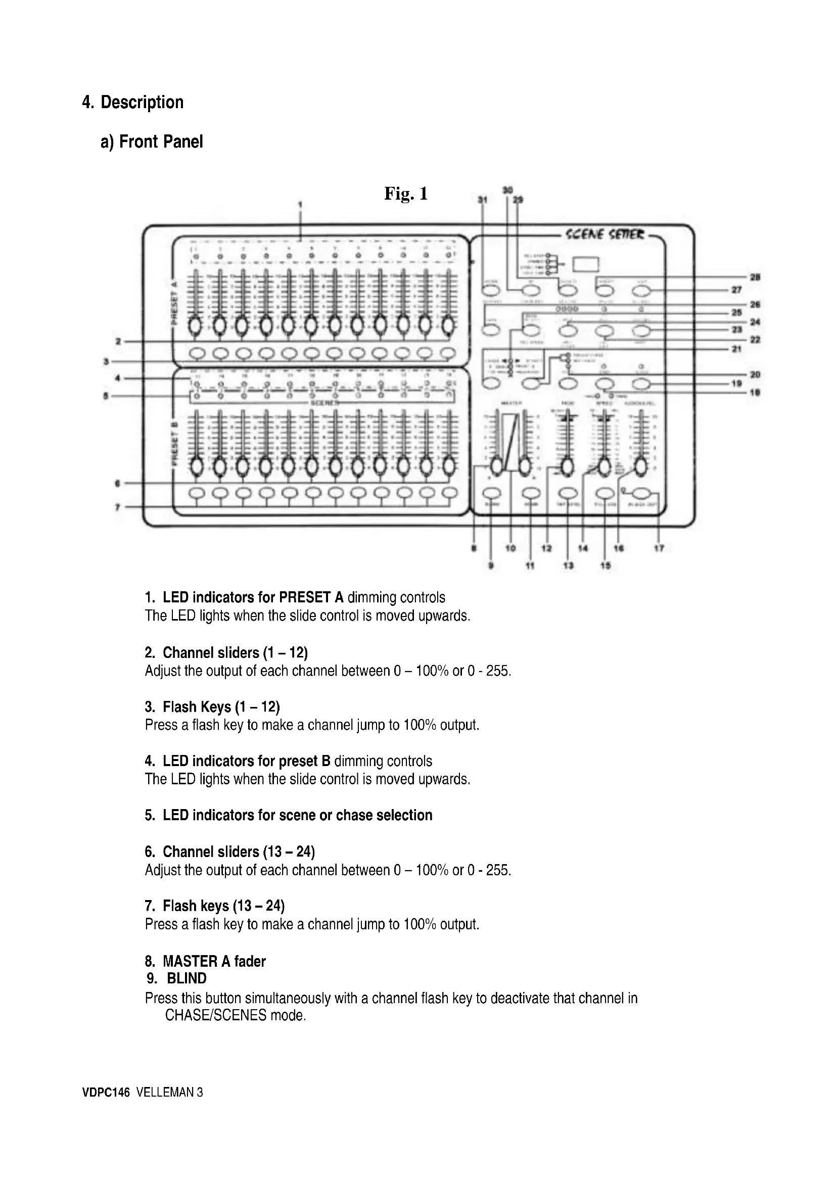
4.Description
a) Front Panel
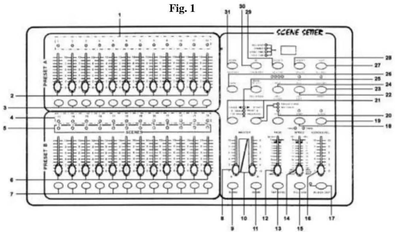
1. LED indicators for PRESET A dimming controls The LED lights when the slide control is moved upwards.
- Channel sliders (1-12) Adjust the output of each channel between 0 - 100% or 0 - 255.
- Flash Keys (1-12) Press a flash key to make a channel jump to 100% output.
- LED indicators for preset B dimming controls The LED lights when the slide control is moved upwards.
- LED indicators for scene or chase selection
- Channel sliders (13 - 24) Adjust the output of each channel between 0 - 100% or 0 - 255.
- Flash keys (13 - 24) Press a flash key to make a channel jump to 100% output.
- MASTER A fader 9.BLIND
Press this button simultaneously with a channel flash key to deactivate that channel in CHASE/SCENES mode.
10. Master B fader
11. HOME
Press this button simultaneously with a channel flash key to reactivate that channel in CHASE/SCENES mode.
12. Fade Time Slider
Adjust the fade time with this slider.
13. TAP SYNC
Press this button twice to the rhythm of the music to define the chase speed during the AUTO CHASE mode.
14. SPEED slider
To adjust the chaser speed manually.
15. FULL ON
Press this button to make all channels jump to 100% output.
16. AUDIO LEVEL slider
Adjusts the music sensitivity of the audio input.
17. BLACK OUT
Press this button to reduce the output of all channels to zero.
18. STEP
Press this button to advance step by step in a programme. (speed slider should be in the lowest position : SHOW MODE)
19. AUDIO
Press this button to access the audio control mode.
20. HOLD
Hold this button to stop the chase.
21. PARK
In DOUBLE PRESET, pressing PARK B activates the maximum value for MASTER B. In SINGLE PRESET, pressing PARK A activates the maximum value for MASTER A.
22. RECENT
Press this button to add or kill a channel. The LED indicator is lit when the device is in kill mode. Press an arbitrary flash button to reduce all channel output levels to zero, with the exception of the selected channel. This button also deactivates the recording mode.
23. RECORD
Press this button to record a step in a programme.
24. PAGE
Select the desired scene or chase on the selected page (1 - 4).
25. MODE SELECT
In the CHASE/SCENES mode, you can press this button to choose between the DOUBLE PRESET or SINGLE PRESET mode.
26. DARK
For a blackout of all channels, including the ones that are currently in FULL ON and FLASH mode.
27. ALL REV
Reverses the direction of a chase.
28. 0% or 0-255
Switches the display from 0-100% to 0-255 and vice versa.
29. REV ONE
Hold this button and press any button of PRESET B. The selected scene will now chase in reverse.
30. CHASE REV
This button enables you to reverse the chase controlled by the SPEED slider.
31. BEAT REV
This button enables you to reverse the chase to the beat of the music.
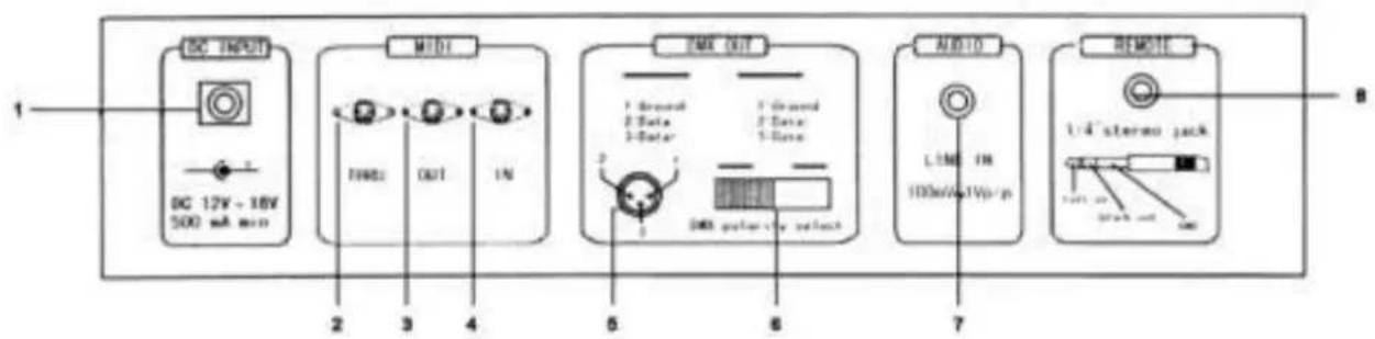
b) Back Panel
Fig. 2
- Power input : 12-20Vdc / 500mA
- MIDI THRU : used to transmit MIDI data received on the MIDI IN connector
- MIDI OUT
- MIDI IN
- DMX OUT : 3-pin female XLR
- DMX POLARITY : select the polarity of the DMX OUT
- AUDIO INPUT : RCA (cinch) line in : 100mV, 1Vp-p
- REMOTE : FULL ON and BLACKOUT can be controlled from a distance using a 1/4 stereo jack (6.35mm)
c) Connections
The manufacturer is not responsible for damage caused by improper connections.
Connect the supplied adapter with the DC jack and connect the other end with a mains outlet.
Plug the XLR cable into the VDPDMXC146 and connect the other end with the first device you wish to control. Plug the MIDI cables into the appropriate MIDI sockets.
5. Operating Instructions
A) Programming
1) Leaving the Recording Mode
- Hold the RECORD button.
- Press the REC EXIT button.
- Release the RECORD button.
The red LED indicator above the RECORD key is now dimmed, meaning that the programming mode has been deactivated and cannot be accessed.
2) Activating the Recording M
- Hold the RECORD button.
- Press the following flash keys in PRESET A:1-5-6-8
- Release the RECORD button.
The red LED indicator above the RECORD key is now lit, meaning that the programming mode has been activated and can be accessed.
3) Erasing all Programmes
- Hold the RECORD button.
- Press the following flash keys in PRESET A:1-3-2-3.
- Release the RECORD button.
4) Clearing the Memory
- Hold the RECORD button.
- Press the REC CLEAR button.
- Release both buttons.
5) Recording a Scene
- Press MODE SELECT to select the 1-24 SINGLE / PRESET PARK function. The green LED indicator lights up.
- Select the desired page with the PAGE button
- Slide both master faders to the top position (MASTER A = 10 & MASTER B = 0)
- Place the 24 channel sliders in the desired position.
- Press the RECORD button to store the scene in the memory.
- Slide both master faders to the lowest position (MASTER A = 0 & MASTER B = 10).
Hold the record button
- Press the flash button of your choice (13-24)
- Release the RECORD button.
The scene is now stored under one of the keys of n^7 in fig. 1 on page 2
6) Deleting a Scene
- Select the desired page with the PAGE button
- Hold the RECORD button.
- Press the flash button (13 - 24) where the scene was stored twice
- Release the RECORD button
7) Recording a Chase
- Press MODE SELECT to select 1-24 SINGLE / PRESET PARK. The green LED indicator lights up.
- Select the desired page with the PAGE button.
- Slide both master faders (MASTER A = 10 and MASTER B = 0) to the highest position
- Place the 24 channel sliders in the desired position.
- Press RECORD to store the scene in the memory
- Place the 24 channel sliders in the desired position again.
- Press RECORD to store this second scene in the memory
- Repeat the last two steps until a max. of 999 scenes have been programmed
- When you're done programming, slide both master faders (MASTER A = 0 and MASTER B = 10) to the bottom
- Press the desired flash button (13 - 24)
- Release the RECORD button
The chase is now stored under one of the keys of n^7 in fig. 1 on page 2.
8) Deleting a Step from a Programme
- Hold the EDIT button
- Press the desired flash button (13 - 24).
- Release the EDIT button. The yellow LED indicator of the selected scene is lit.
- Bring the speed fader down (to SHOW MODE) and use the STEP button to find the scene to be deleted
- Press the DELETE button to remove the step.
9) Inserting or Adding a Step to a Programme
- Press MODE SELECT to select 1-24 SINGLE / PRESET PARK. The green LED indicator lights.
- Use the PAGE button to select the page (1 - 4) where the scene is to be added or inserted.
- Slide both master faders (MASTER A = 0 and MASTER B = 10) to the lowest position, place the FADE slider in the highest position and the SPEED slider in the lowest position (SHOW MODE).
- The channel fader of the step to be inserted should be slid upwards.
- Press RECORD
- Select CHASE/SCENES (red LED indicator is lit) with the MODE SELECT button
- Hold the EDIT button
- Press the flash button of the scene that has to be inserted in that step.
- Release the EDIT button (the yellow LED indicator of the selected scene is lit)
- Press the STEP button until you reach the scene that will immediately follow the scene to be inserted
- Press INSERT to add the scene to that programme step.
- Hold the RECORD button
- Press the REC EXIT button
- Release both buttons to leave the programming mode
10) Selecting and Running a Programme
- Press MODE SELECT until the green LED indicator marked '1-24 SINGLE / PRESET PARK' is lit.
- Select the desired page (1 - 4) with the PAGE button
- Slide the MASTER faders to the highest position
- Move the channel slider for the scene in question to the lowest and then the highest position to select and run the programme stored under that fader.
11) Running a Programme with TAP SYNC rhythm control
- Make sure the music control function is not active (press the AUDIO button to extinguish the AUDIO LED indicator if necessary).
- Press the PARK button to select MIX CHASE. The yellow LED indicator is lit
- Select the programme you want to run
- Adjust the speed slider and press TAP SYNC twice to define the beat time
- Hold REC SPEED.
- Press the appropriate flash button under PRESET B to store the new settings
12) Running a Programme with the Speed Slider
- Make sure the music control function is not active (press the AUDIO to extinguish the AUDIO LED indicator if necessary).
- Press the PARK button to select MIX CHASE. The yellow LED indicator is lit
- Select the programme you want to run
- Move the speed slider all the way down to SHOW MODE
- Hold REC SPEED.
- Press the appropriate flash button under PRESET B to store the new settings
The programme is now controlled through the real-time movement of the SPEED control.
13) Programming Example
- Put the device in the programming mode (see "2") Record Enable (enter recording mode) on page 5)
- Press MODE SELECT until the green LED indicator marked '1-24 SINGLE / PRESET PARK' is lit
- Slide both MASTER faders and the FADE slider to the highest position and the SPEED slider to the bottom.
- Select page 1 with the PAGE button
- Slide channel faders 1-3-5-7-9-11-13-15-17-19-21-23 to the top
- Press RECORD (the LED display shows 001)
- Slide channel faders 2-4-6-8-10-12-14-16-18-20-22-24 to the top
- Press RECORD (the LED display shows 002)
- Select CHASE / SCENES by pressing the MODE SELECT button
- Hold the RECORD button
- Press the first flash button in the lower channel faders portion (the flash button of channel 13)
- Release both buttons. All LED channel indicators flash momentarily. The running light is now programmed on page 1 under scene 1.
Now we want to see the light in action :
- Slide both master faders to the bottom
- Slide the SPEEDD fader to the top
- Slide SCENE 1 fader to the top
Move the SPEED fader up or down to adjust the speed of the running light. When the SPEED fader is all the way down and is on SHOW MODE, then you can press the STEP button to view the scene step by step.
Press the AUDIO button (the green LED indicator will light) if you want the running light to react to music. Adjust the music sensitivity with the AUDIOLEVEL fader. Press the AUDIO button again to leave the music control mode.
You can also synchronize the running light with the music manually : Tap the TAP SYNC button twice. The interval between the two taps will determine the rhythm of the running light. In other words : tap the button twice to the beat of the music. The SPEED fader will resume control when it is moved.
B) Speed Settings
1) Speed adjustment (max. 5 min):
Hold the RECORD button
- Press flash key 5 in PRESET A three times
- Release the RECORD button
The yellow LED indicator next to 5MIN (left) is now lit, indicating that the left scale is currently being used for the SPEED fader.
2) Speed adjustment (max. 10 min):
Hold the RECORD button
- Press flash key 10 in PRESET A three times
- Release the RECORD button
The yellow LED indicator next to 10MIN (right) is now lit, indicating that the left scale is now being used for the SPEED fader.
C) Other Functions
- Hold the BLIND button.
- Press the flash button to any channel to deactivate this channel.
- Hold the HOME button.
- Press the flash button for any channel to reactivate this channel.
- Press this button twice to define the rhythm of the music manually (this only works in STEP mode and not in the AUDIO mode). The interval between the two taps determines the speed)
- All channel outputs go to 100% as long as the user holds this button.
- The programme continues to run but the connected devices do not receive the signal as long as the yellow BLACK OUT indication LED is lit.
- Press the BLACK OUT button again to deactivate this function.
D) Midi Settings
1. MIDI-IN mode
Hold the RECORD button
- Press flash button 1 three times in PRESET A
- Release the RECORD button
- The display now shows CH1, indicating that the device is in the MIDI-IN mode
- Press the desired flash button (1 - 16) to assign this MIDI channel to this DMX channel
- Hold the RECORD button
- Press the REC EXIT button to leave this mode
VDPC146 VELLEMAN 9
2. MIDI-OUT mode
- Hold the RECORD button
- Press flash button 2 three times in PRESET A
- Release the RECORD button
- The display now shows CHO, indicating that the device is in the MIDI-OUT mode
- Press the desired flash button (1 - 16) to assign this MIDI channel to this DMX channel
- Hold the RECORD button
- Press the REC EXIT button to leave this mode
3. Receiving a File
- Hold the RECORD button
- Press flash button 3 three times in PRESET A
- Release the RECORD button
- The display now shows IN, indicating that the device is ready to receive a file
- All other operations will be disabled during the reception of the file. The reception will stop automatically at the end of the file or when mistakes occur.
4. Sending a File
- Hold the RECORD button
- Press flash button 4 three times in PRESET A
- Release the RECORD button
- The display now shows OUT, indicating that the device is ready to send a file
- All other operations will be disabled during the reception of the file. The transmission will stop automatically at the end of the file or if an error occurs.
E) Special Functions
1. Fade Time
The amount of time required to dim the output from 100 to 0% or vice versa.
2. Single Chase
The scenes are executed one by one and NO is showing on the display. Adjust the speed with the SPEED fader.
3. Mix Mode
All selected programmes are executed synchronously, with each programme having its own chase speed.
4. Fade Time & Chase Speed Indications
When the time is more than 1 min, the indication includes 2 dots e.g. 1 minute and 15 seconds is displayed as 1.15.
When the time is less than one minute, the indication only has one dot e.g.11.5 seconds is displayed as 11.5
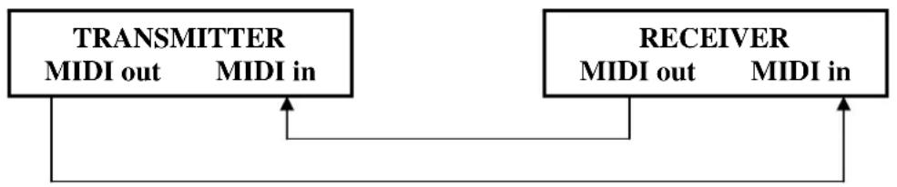
5. Transmit and Receive MIDI files
Open-loop mode

Closed-loop mode
6. Low Power
When the power voltage is low, the display will show LOP. Please check your power supply. LOP may appear briefly just after you have turned the device on. Pay no attention to this, it's normal.
7. MIDI Run
- If no MIDl data are received for ten minutes, the VDPDMXC146 goes to standby mode.
- You need to enter the device ID (= 55H) in order to send or receive a file. You can add scenes to the memory or call them up and you can exchange information with a device that is connected to your VDPDMXC146.
This unit sends or receives NOTE information as follows:
| NOTE NUMBER VELOCITY FUNCTION | |
| 22 - 69 Programme Master Turn on/off programme 1 - 48 | |
| 70 - 93 Channel Dimmer Turn on/off channel 1 - 24 | |
| 94 | chase | FULL-ON |
| 95 | DARK |
| 96 | HOLD |
| 97 Turn on/off audio | |
| 98 CHASE / SCENES mode | |
| 99 DOUBLE PRESET mode | |
| 100 SINGLE PRESET mode | |
| 101 | | Step |
| 102 | | BLACK OUT |
8. Switch the display between 0 - 100% and 0-255
- Hold the RECORD button
- Press the % OR 0-255 key
- Release the RECORD button
6. Cleaning and Maintenance
- All screws for installing the devices or parts of the device have to be screwed down tight and must not be corroded.
- The housing, mounting supports and connections should not be modified or tampered with e.g. do not drill extra holes in mounting supports, do not change the location of the connections, etc.
- The electric power supply cables must be undamaged. Have the device installed by a qualified technician.
- Disconnect the device from the main prior to maintenance activities.
- Wipe the device regularly with a moist cloth. Do not use alcohol or solvents.
- Entrust a qualified technician with the maintenance of this device. Contact your dealer for spare parts if necessary.
7. Technical Specifications
| Power Supply | AC/DC adapter 12-20Vdc/500mA |
| Number of DMX Channels | 24 |
| Max. Cable Length | 100m |
| DMX Output | 3-pin female XLR |
| Audio Line Input | RCA (cinch) 100mV, 1Vp-p |
| MIDI Input, Output, Throughput | 5-pin Din standard interface |
| Foot Control Input | 6.35mm stereo socket |
| Fuse | F0.5A (5 x 20mm) 250V (order the F=0.5N with us) |
| Dimensions | 482 x 264 x 85mm |
| Weight | 4.8kg |
The information in this manual is subject to change without prior notice.
VDPC146 - 24-KANAALS DMX LICHTSTURING
5-pin Din standard interface
6.35mm stereo
F0.5A (5 x 20mm) 250V (order code FF0.5N)
482 x 264 x 85mm
4.8kg
7. Specifications techniques
Vellem an® Service and Quality Warranty
Velleman® has over 35 years of experience in the electronics world and distributes its products in more than 85 countries.
All our products fulfil strict quality requirements and legal stipulations in the EU. In order to ensure the quality, our products regularly go through an extra quality check, both by an internal quality department and by specialized external organisations. If, all precautionary measures notwithstanding, problems should occur, please make appeal to our warranty (see guarantee conditions).
General Warranty Conditions Concerning Consumer Products (for EU):
All consumer products are subject to a 24-month warranty on production flaws and defective material as from the original date of purchase.
- Vellem an can deo replace an article with an equivalent artie, or to refund the retail value totally or partially when the complaint is valid and a free repair or replacement of the article is impossible, or if the expenses are out of proportion.
You will be delivered a replacing article or a refund at the value of 100% of the purchase price in case of a flaw occurred in the first year after the date of purchase and delivery, or a replacing article at 50% of the purchase price or a refund at the value of 50% of the retail value in case of a flaw occurred in the second year after the date of purchase and delivery.
Not covered by warranty:
- all direct or indirect damage caused after delivery to the article (e.g. by oxidation, shocks, falls, dust, dirt, humidity...), and by the article, as well as its contents (e.g. data loss), compensation for loss of profits;
- frequently replaced consumable goods, parts or accessories such as batteries, lamps, rubber parts, drive belts... (unlimited list);
flaws resulting from fire, water damage, lightning, accident, natural disaster, etc. ...
- flaws caused deliberately, negligently or resulting from improper handling, negligent maintenance, abusive use or use contrary to the manufacturer's instructions;
- damage caused by a commercial, professional or collective use of the article (the warranty validity will be reduced to six (6) months when the article is used professionally);
- damage resulting from an inappropriate packing and shipping of the article;
- all damage caused by modification, repair or alteration performed by a third party without written permission by Velleman®
- Articles to be repaired must be delivered to your Velleman® dealer, solidly packed (preferably in the original packaging), and be completed with the original receipt of purchase and a clear flaw description.
Hint: In order to save on cost and time, please reread the manual and check if the flaw is caused by obvious causes prior to presenting the article for repair. Note
that returning a non-defective article can also involve handling costs
- Repairs occurring after warranty expiration are subject to shipping costs.
The above conditions are without prejudice to all comm ercial warranties.
The above enumeration is subject to modification according to the article (see article's manual).