SWP 475 - Sweeper STIGA - Free user manual and instructions
Find the device manual for free SWP 475 STIGA in PDF.

User questions about SWP 475 STIGA
0 question about this device. Answer the ones you know or ask your own.
Ask a new question about this device
Download the instructions for your Sweeper in PDF format for free! Find your manual SWP 475 - STIGA and take your electronic device back in hand. On this page are published all the documents necessary for the use of your device. SWP 475 by STIGA.
USER MANUAL SWP 475 STIGA
natural_image
Line drawing of a mobile phone with a flat-screen screen and wheels (no text or symbols)IT SPAZZATRICE MANUALE DI ISTRUZIONI
CS ZAMETAČ NÁVOD K POUŽITÍ
DA FEJEMASKINE BRUGSANVISNING
natural_image
Technical line drawing of a mechanical device with no visible text or symbolsFig. 12: Prelievo del fi Itro antipolvere
natural_image
Technical line drawing of a mechanical device with no visible text or symbolsFig. 1: Komponentoversigt 1
Fig. 2: Komponentoversigt 2
Fig. 3: Komponentoversigt 3
natural_image
Technical line drawing of a mechanical device with no visible text or symbolsFig. 5: Opbevaringsposition
Fig. 6: Bær enheden
Fig. 10: Nedholder indstilling
Fig. 11: Aff aldsbeholderen tømme
natural_image
Technical line drawing of a mechanical device with no visible text or symbolsAbb. 7: Griff beschlagmontage (haaga 375)
1.1 Conventions....60
1.2 Symbols and labels 60
1.3 Limitation of Liability....60
1.4 Warranty 60
1.5 Copyright....61
1.6 Target group....61
- Safety 61
2.1 Intended use....61
2.2 Improper use....61
2.3 Responsibility of the user....61
2.4 General safety instructions 62
2.5 Hazard notices on the device 62
2.6 Personal Safety Equipment 62
-
Technical data 62
-
Construction and Function 63
-
Transport/transporting 64
5.1 Delivery....64
5.2 Scope of supply 64
5.3 Handling Packaging Materials....64
5.4 Storage 64
5.5 Carrying the device 65
5.6 Transporting the device in a vehicle....65
- Commissioning 66
6.1 Assemble handle fittings (SWP 475)....66
6.2 Install sliding bracket....66
- Operation 67
7.1 Before starting work....67
7.2 Height adjustment of the plate brooms....67
7.3 Set hold-down device (SWP 577) 68
7.4 Operation....68
7.5 Empty sweeping container 68
- Troubleshooting....69
8.1 Fault table....69
- Maintenance and cleaning 70
9.1 Maintenance plan....70
9.2 Clean dust filter (SWP 577)....71
9.3 Remove blockage 71
9.4 Align bristles....71
9.5 Clean the device 71
- Decommissioning 72
10.1 Disassemble sliding bracket 72
10.2 Disposal....72
1. General
This operating manual is a part of the device Sweeping Machine SWP 475 and SWP 577 and is valid only for the named devices.
This operating manual provides important information for the safe and efficient use of the machine.
A requirement for safe operation of the machine is the adherence to all of the safety and operation instructions provided.
- Read the operating manual carefully before using the device.
- Read the safety instructions!
- Keep the operating manual safe and accessible during the lifespan of the device.
• Pass the operating manual onto any subsequent owner or user of the device.
1.1 Conventions
To be able to work optimally with the operating manual, please note the following explanations of the typographical conventions.
Numbering
- The texts shown are first level numbering points.
Work sequence
- Step 1 of the work sequence
- Step 2 of the work sequence
- Step 3 of the work sequence
The sequence of the work steps must be observed.
Tip
» Tips and notes (not machine damage) are shown like this.
1.2 Symbols and labels
All warnings and safety instructions must be complied with! When working, always act with caution to prevent accidents, personal injury and damage to property!
Safety instructions

SIGNAL WORD
Type and source of hazard
Possible consequences
• Measures for avoiding danger
Risk level
Risk level Probability
of occurrence Consequences in the event of noncompliance

DANGER
Direct Death, serious injury

WARNING
Possible Death, serious injury

CAUTION
Possible
Slight injury
NOTE Possible material damage
1.3 Limitation of Liability
The manufacturer does not accept any liability for damage and consequential damage caused by the following points:
- Failure to observe the operating instructions
- Use of nonapproved replacement parts / wrong spare parts / spare parts that do not correspond to the manufacturer's specification
- Unauthorized changes, additions to and modifications to the device
1.4 Warranty
The provisions that are described in the general terms and conditions of the manufacturer apply.
1.5 Copyright
The operating manual is copyright protected for the manufacturer.
The operating manual includes instructions and diagrams or diagram sections of a technical nature, which may not be reproduced in the entirety or in part, distributed or used for competition purposes or otherwise communicated.
The manufacturer reserves all rights for the provision of permission for use for publication or distribution of copies or information from this operating manual to third parties.
In case of infringement the manufacture is entitled to make a claim for damages. Further claims are reserved.
1.6 Target group
This operating manual is intended for the use of this sweeping machine.
2. Safety
To avoid incorrect functioning, damage and health impairments, please observe the following instructions!
2.1 Intended use
The SWP 475 / 577 sweeping machines are only for removal of road pollution such as foliage, grass, split, sand and similar impurities on flat and hard surfaces.
2.2 Improper use
Any use other than that described in the section "Intended use" is not in compliance with the intended purpose. The operator of the device alone is liable for any resulting damage.
The sweeping machine may not be used for sweeping hazardous, flammable or glowing substances (cigarettes and matches) liquids, explosive or hazardous dusts (ex), acids or solvents.
The sweeping machine may also not be used for sweeping water.
The sweeping machine may not be used in areas where there is a risk of explosion or as a means of transport.
2.3 Responsibility of the user
A user is any individual or legal entity, who uses the machine or has it used by third parties and is responsible during its use for the safety of the user or third parties.
- Supervise children who are in the working environment, to ensure that they do not play with it.
- Minors may not work with the device. Young people over the age of 16 years who are being trained under supervision are excluded.
- Persons, whose reaction times are influenced by, e.g. drugs, alcohol or medications, may not carry out any work with the device.
- Persons who are not allowed to do strenuous work due to their health status may not work with the sweeping machine.
- Replace any signs that have become illegible on the sweeping machine.
Safety
Technical data
SWP 475 / 577
2.4 General safety instructions
- Keep the packaging material out of reach of children. There is a risk of suffocation!
- Do not wear long hair, ties, loose clothing or jewellery including rings.
- When handling the sweeping machine please note that there is a risk of injury from hanging or being pulled in.
2.5 Hazard notices on the device
The following pictograms are affi xed to the sweeping machine:

CAUTION
When working on the machine, the safety instructions described in the operating manual must be observed.

Operating instructions
Read the operating manual carefully before using the device.
2.6 Personal Safety Equipment
Personal safety equipment must be worn when working to minimise health hazards. For that reason:
- Before starting all work put on each item of specified safety equipment properly and wear it during work.

Sturdy footwear
Wear sturdy footwear with well-gripping, non-slip soles.

Protective gloves
Wear protective gloves.

Dust protection mask
Wear a dust protection mask.
3. Technical data
Basic information for the SWP475 Sweeping Machine
| Technical data Value | |
| Height in millimetres [mm] 1200 | |
| Width in millimetres [mm] 770 | |
| Length in millimetres [mm] 800 | |
| Sweeping width in millimetres [mm] 750 | |
| Sweeping capacity in square metres per hour [ m^2/h ] | 2900 |
| Capacity of the sweeping container in litres [l] | 50 |
| Weight kilogrammes [kg] 11 |
Basic information for the SWP 577 Sweeping Machine
| Technical data Value | |
| Height in millimetres [mm] 1200 | |
| Width in millimetres [mm] 770 | |
| Length in millimetres [mm] 800 | |
| Sweeping width in millimetres [mm] 770 | |
| Sweeping capacity in square metres per hour [ m^2/h ] | 3000 |
| Capacity of the sweeping container in litres [l] | 50 |
| Weight kilogrammes [kg] 15 |
- Construction and Function
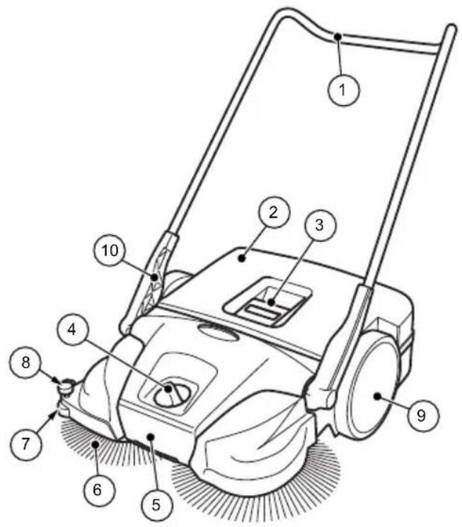
Fig. 1: Component overview 1
| Item no. | Component |
| 1 | Sliding bracket |
| 2 | Sweeping container |
| 3 | Container handle |
| 4 | Plate brooms – height adjustment |
| 5 | Carrying handle |
| 6 | Plate brooms |
| 7 | Lateral guide roller |
| 8 | Hold-down device (SWP 577) |
| 9 | Impeller |
| 10 | Handle fitting |
The device is moved forward by pushing, via the sliding bracket (1). At the same time the 2 plate brooms (6) convey the sweepings in the direction of the sweeping container (2) with the aid of the sweeper lip (13). The fine dirt sweeping roll (11) conveys the rest of the sweepings into the sweeping container (2).
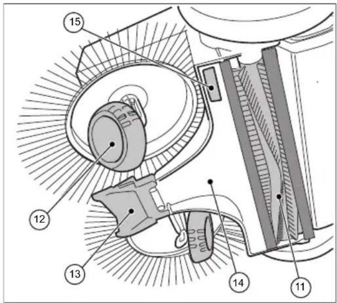
Fig. 2: Component overview 2
| Item no. | Component |
| 11 | Fine sweeping roll |
| 12 | Helical gear |
| 13 | Sweeper lip |
| 14 | Sweeping plate |
| 15 | Name plate (SWP 475) |
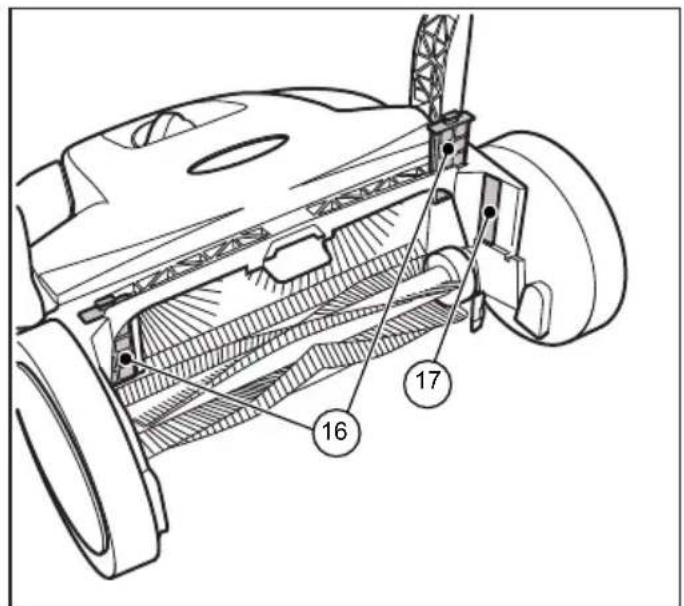
Fig. 3: Component overview 3
| Item no. Component |
| 16 Dust filter (SWP 577) |
| 17 Name plate (SWP 577) |
Construction and Function Transport/transporting
SWP 475 / 577
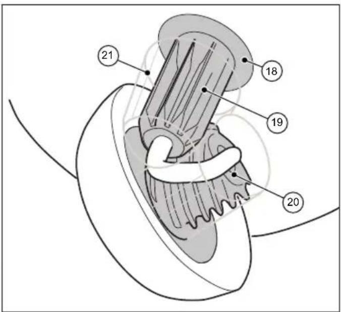
Fig. 4: Component view 4
| Item no. Component | |
| 18 Clutch housing | |
| 19 Toothed sleeve | |
| 20 Helical gear toothing | |
| 21 Gearbox protection (SWP 577) |
5. Transport/transporting
5.1 Delivery
NOTE
Visible damage on the outer packing must be immediately confirmed on delivery by the parcel service driver. If transport damage is only noticed during unpacking, the parcel service must be notified in writing within 24 hours after delivery so that it can be liable for the damage.
5.2 Scope of supply
- Device
- Sliding bracket
- Two handle fi ttings (SWP 475)
- Operating instructions
5.3 Handling Packaging Materials
• Always dispose of packing in an environmentally responsible manner.
- Observe the local and regional legal provisions in force.
5.4 Storage
NOTE
Improper storage, e.g. storage of the device in a humid environment, can lead to damage to the sweeper.
- Store the sweeping machine only in cleaned condition and with an emptied sweeping container.
» Information on emptying the sweeping container can be found in Section 7.5 and information on cleaning can be found in Section 9.5 of this operating manual.
natural_image
Technical line drawing of a mechanical device with no visible text or symbolsFig. 5: Storage position
- Place the device in such a way that the bristles cannot be kinked or bent.
- Secure the device including sliding brackets against tipping over, slipping and thus against damage.
- Do not store the device outdoors or in damp environments.
5.5 Carrying the device

CAUTION
Risk of injury through tipping over of the sliding bracket!
Tipping over of the sliding bracket may lead to slight injuries, such as jamming of the finger o haematomas in users or other persons.
- When carrying the device, hold it so that the sliding bracket cannot tip over
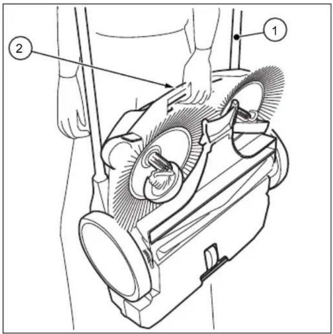
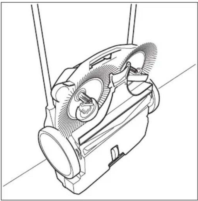
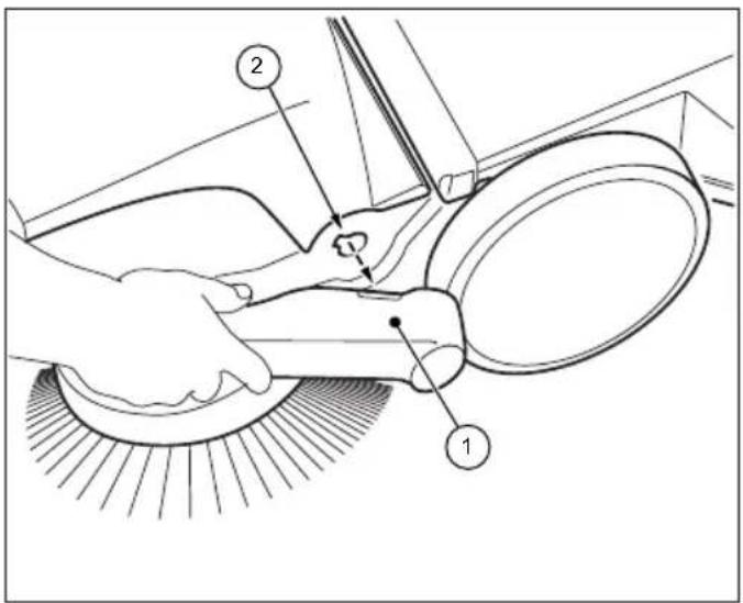
Fig. 6: Carrying the device
- Swing the sliding bracket (1) fl at towards the front.
- Grasp the device on the carrying handle (2).
- Carry the device in such a manner that the plate brooms face away from the body.
5.6 Transporting the device in a vehicle

CAUTION
Risk of injury through improper transport of the sweeping machine!
Wandering, skidding or tipping of the device can result in injury to the driver or other persons
- Secure the device with a strap to prevent it from slipping and moving around.
- Place the device in a suitable location in the vehicle.
- Secure the device with a strap.
NOTE
Improper transport can result in damage to the sweeping machine.
6. Commissioning
6.1 Assemble handle fi ttings (SWP 475)
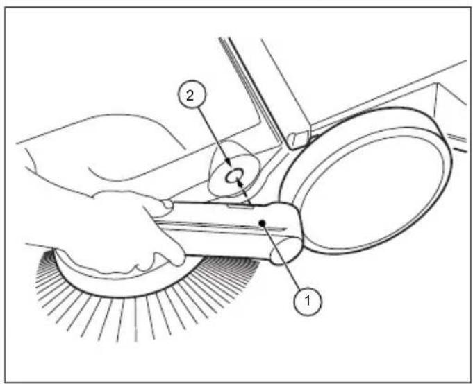
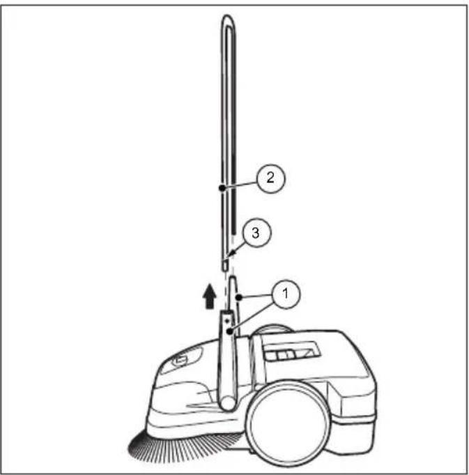
Fig. 7: Handle fi tting assembly (SWP 475)
Two handle fittings (1) and the sliding bracket are included as individual parts in the delivery.
- Position the handle fittings (1) as shown in Figure 7.
- Insert the handle fi ttings in this position into the intended receptacle (2) of the sweeper. It may be necessary to slightly hit the handle fi ttings in this step.
» Make sure that the handle fittings audibly click into the device.
6.2 Install sliding bracket

CAUTION
Risk of injury through tipping over of the sliding bracket!
Tipping over of the sliding bracket may lead to slight injuries, such as jamming of the finger o haematomas in users or other persons.
- When carrying the device, hold it so that the sliding bracket cannot tip over
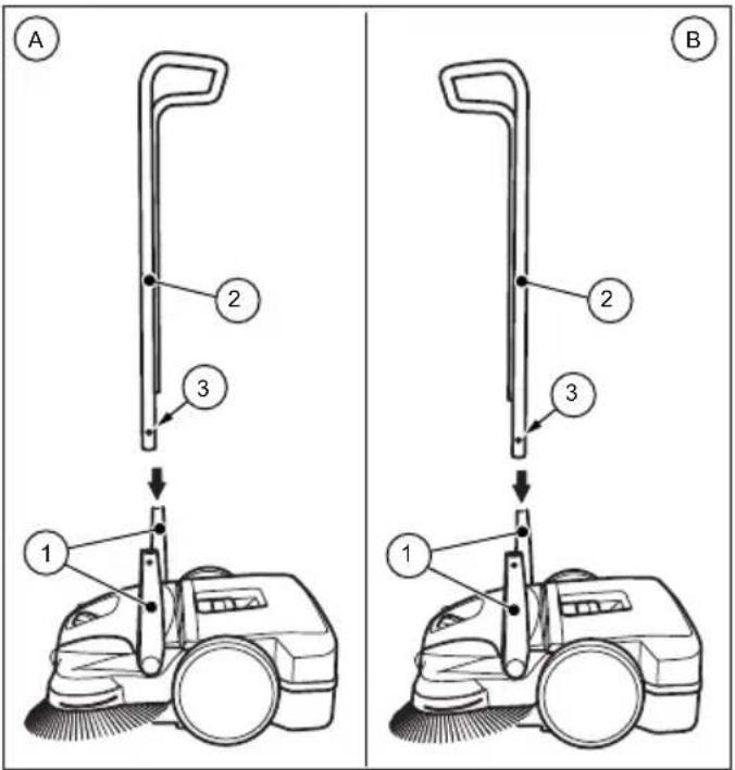
Sliding bracket for SWP 577
The sliding bracket can be adjusted to the height of the user in two levels (A) and (B).
» (A): Lower level
» (B): Upper level
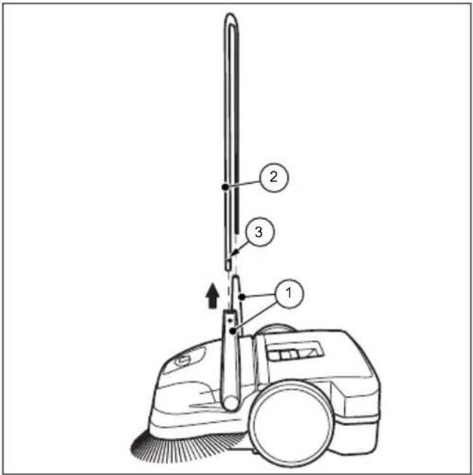
Fig. 8: Sliding bracket assembly
- Turn the handles (1) into the vertical position.
- Press the locking springs (3) inwards on both sides of the sliding bracket.
- Push the sliding bracket (2) into both handle fi ttings simultaneously.
» To do so, the SWP 577 sliding bracket must bent apart by about 10 cm before insertion in the handle fi ttings. - Push the sliding bracket (2) into the handle fittings until the locking springs lock in.
7. Operation

WARNING
Risk of cutting due to broken glass, metal or other sharp edged materials!
When emptying the sweeping container, cutting injuries may occur due to broken glass, metal or other sharp edged materials.
- Wear the prescribed personal protective equipment!

CAUTION
Health impairments caused by dust resulting from sweeping!
The inhalation of dusts can endanger the health
- Wear the prescribed personal protective equipment!
7.1 Before starting work
- Check the device to make sure that it is functioning before starting work.
- Check the sliding bracket to make sure that it is firmly fixed in the handle fittings.
- Check the sweeping container to make sure it is firmly fixed and in good condition.
- Check the plate brooms and the fine dust sweeping roller for rolled up threads and cords. Remove these if necessary.
- Check the plate brooms and the fine dust sweeping roller for jammed items or contamination.
- Check the handle for contamination and clean its if necessary.
7.2 Height adjustment of the plate brooms
The height of the brooms is adjusted with a dial in the middle of the front part. The height adjustment sets the plate brooms to the surface to be swept. The levels are based on empirical values and must therefore be considered as the levels are based on empirical values and must therefore be regarded as reference values. As a result, during sweeping, adaptations of the levels may need to be made depending on the surface.
• Level 1-2: for all level, hard surfaces
(e.g. asphalt, concrete, slabs...)
• Level 3-4: for damp leaves, sand, and uneven surfaces (e.g. washed concrete slabs)
• Level 5-7: for heavy soiling and severely uneven surfaces
- Level 8: for service settings, not suitable for sweeping
NOTE
Do not press the plate brooms too firmly or the ground. A too high pressure does not achieve a better cleaning result, but rather leads to an increase in the pushing resistance and the wear of the device.
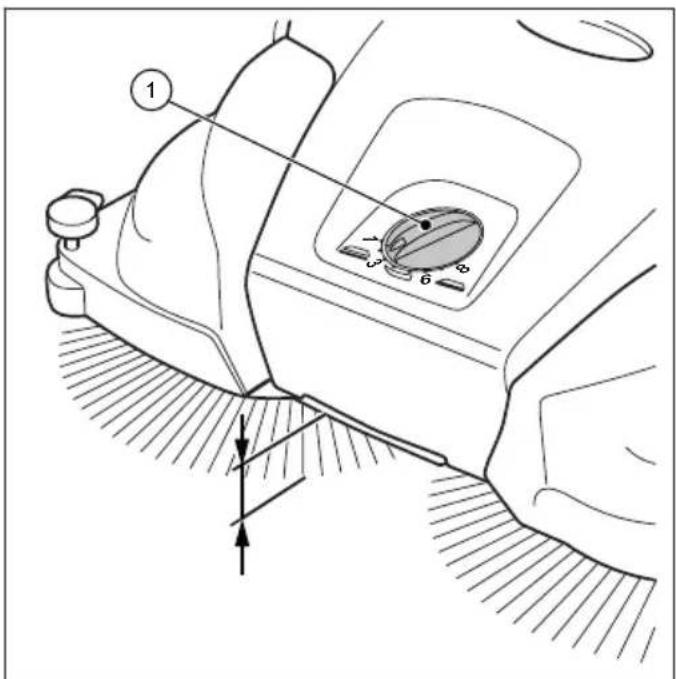
Fig. 9: Height adjustment of the plate brooms
- Set the required level:
- Turn the dial (1) to the left to lower the level.
- Turn the dial (1) to the right to increase the level.
» Lift the machine slightly by the handle. This will make it easier to adjust the height.
7.3 Set hold-down device (SWP 577)
With the hold-down device, the right plate broom is adjusted to the edge regions to be swept, for example on walls or curbs.
NOTE
An unsuitable setting of the hold-down device at lower edges can lead to excessive wear. The hold-down device must not scratch on the ground.
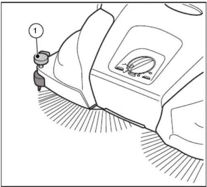
Fig. 10: Hold-down device setting
Sweeping out edges and corners
- Press down the handle of the hold-down device.
Operation on surfaces
- Pull up the handle of the hold-down device.
7.4 Operation
- Operate the device via the sliding bracket with both hands.
- Push the device forward at normal walking speed.
- Remove the sweeping container as needed, see section "Empty sweeping container" in Section 7.5 of this operating manual.
7.5 Empty sweeping container
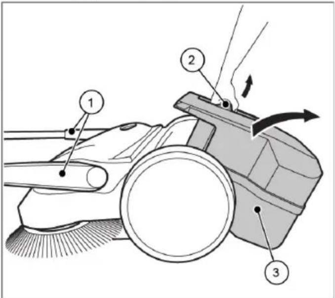
Fig. 11: Empty the sweeping container
-
Empty the sweeping container after each use.
• Empty the sweeping container at regular intervals to achieve a proper sweeping result. -
Bring the sliding bracket (1) into the horizontal position.
- Pull the sweeping container (3) upwards by the container handle (2).
- Empty the sweeping container (3) completely.
» Make sure that the enclosure sides are free of dirt.
4. Insert the empty sweeping container (3) on the device.
5. Press the container handle (2) back into the starting position.
» The sweeping container (3) must audibly lock into position.
6. Bring the sliding bracket (1) back into the operating position.
8. Troubleshooting

WARNING
Risk of cutting due to broken glass, metal or other sharp edged materials!
When emptying the sweeping container, cutting injuries may occur due to broken glass, metal or other sharp edged materials.
- Wear the prescribed personal protective equipment!

CAUTION
Health impairments caused by dust resulting from sweeping!
The inhalation of dusts can endanger the health
- Wear the prescribed personal protective equipment!

CAUTION
Risk of injury through tipping over of the sliding bracket!
Tipping over of the sliding bracket may lead to slight injuries, such as jamming of the finger o haematomas in users or other persons.
- When carrying the device, hold it so that the sliding bracket cannot tip over
Faults may occur even if the prescribed maintenance work and checks of the device before use are complied with. Possible faults are listed in the table below, with specification of the cause and remedy.
8.1 Fault table
| Fault Cause Remedy | ||
| Device is running with diffi culty or roughly | Device is contaminated | Clean device, see Section 9.5 |
| Broom blocked Remove blockage see Section 9.3 “Remove blockage” | ||
| Contaminated broom drives | Clean broom drives, see Section 9.5 “Clean device” | |
| Height adjustment is set too low, contact pressure of the plate brooms too high | Set height adjustment, see Section 7.2 in the section “Adjust height of plate brooms” | |
| Plate brooms do not rotate | Contact Service | |
| Bristles are bent | Improper storage | Align the bristles, see Chapter 9.4 in the section “Align bristles” |
| Sweeping result is insufficient | Sweeping lip is missing, loose or worn | Replace sweeping lip |
9. Maintenance and cleaning

WARNING
Risk of cutting due to broken glass, metal or other sharp edged materials!
When emptying the sweeping container, cutting injuries may occur due to broken glass, metal or other sharp edged materials.
- Wear the prescribed personal protective equipment!

CAUTION
Health impairments caused by dust resulting from sweeping!
The inhalation of dusts can endanger the health
- Wear the prescribed personal protective equipment!

CAUTION
Risk of injury through tipping over of the sliding bracket!
Tipping over of the sliding bracket may lead to slight injuries, such as jamming of the finger o haematomas in users or other persons.
- When carrying the device, hold it so that the sliding bracket cannot tip over

CAUTION
Hazard due to cleaning materials!
The agents can contain harmful ingredients and can thereby cause irritation of the respiratory tract and the skin
- Observe the manufacturer's safety data sheet.
- Avoid spillage and the formation of fog.
• Do not eat, drink or smoke while working. - Avoid contact with skin and eyes.
In the following sections the maintenance and cleaning work required for optimal and fault-free operation is described.
The conduct of the specified work depends in some cases on time and/or load. For the maintenance interval information shown both in deadlines and service hours, the one that occurs first applies.
In case of questions on the maintenance work and intervals contact the manufacturer.
9.1 Maintenance plan
| Maintenance interval | Maintenance work |
| Before starting work | Check the device to make sure that it is functioning before starting work. If necessary, contact the Service. |
| Check the sliding bracket to make sure that it is fi rmly fi xed in the handle fi ttings. | |
| Check the sweeping container to make sure it is fi rmly fi xed and in good condition. | |
| Check the plate brooms and the fi ne dust sweeping roller for rolled up threads and cords. Remove these if necessary. | |
| Check the plate brooms and the fi ne dust sweeping roller for jammed items or contamination. | |
| Check the handles for contamination and clean if necessary. | |
| Check that the height adjustment is at the correct height. | |
| Check the sweeping pressure setting. Adapt the sweeping pressure to the surface to be swept, if necessary. | |
| After fi nishing work | Empty the sweeping container. |
| Clean the device. | |
| 8 Bh Clean broom drives. | |
9.2 Clean dust fi Iter (SWP 577)
- Remove the sweeping container from the sweeping machine, see section "Empty sweeping container" in Section 7.5 of this operating manual.
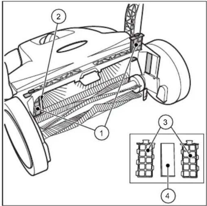
Fig. 12: Dust fi Iter removal
- Pull the dust filter (1) up from the guides (2).
- Open the plastic housing (3) of the dust fi lter and remove the foam insert (4).
- Pound out the foam insert (4) and clean it with water.
- Place the dry foam insert back into the plastic housing.
- Slide the dust fi Iter back into the guides.
- Insert the sweeping container into the sweeping machine.
9.3 Remove blockage
- Remove wound-up material (e.g. cords, threads, etc.) from the brooms and axes.
- Remove jammed material (e.g. stones, twigs, leaves etc.).
9.4 Align bristles

WARNING
Fire hazard due to improper handling of a fan or the use of an unsuitable fan!
When aligning the bristles, there is a risk of fire if they are heated to too high temperatures
- Do not use open flames or furnace to heat the bristles!
- Do not use a hot air blower. If the air is too hot, the bristles may melt.
Bent bristles can be straightened out again with heating by means of a warm air fan (e.g. hairdryer).
- Point the switched-on warm air fan towards the bent bristles.
» If the heating is sufficient, the bristles will straighten out again by themselves.
9.5 Clean the device
- Do not use a degreasing agent.
- Do not use any aggressive cleaning agents.
- Do not clean the device with a high-pressure cleaner or under running water. The device may not be immersed in water or cleaned with water.
- Protect the bearings against moisture.
- Do not clean the plate brooms and the fine dirt sweeping roll with compressed air.
» The strong air jet can damage the bristles. - Clean the plate brooms, the fi ne dirt sweeping roll and the drives with a wet cloth.
- Clean all plastic parts with a damp cloth.
10. Decommissioning
10.1 Disassemble sliding bracket

CAUTION
Risk of injury through tipping over of the sliding bracket!
Lipping over of the sliding bracket may lead to slight injuries, such as jamming of the finger o haematomas in users or other persons.
- When carrying the device, hold it so that the sliding bracket cannot tip over
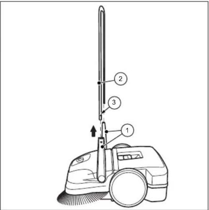
Fig. 13: Sliding bracket disassembly (SWP 475)
- Bring the sliding bracket (2) into the vertical position.
- Press the lock springs (3) inwards on both sides, so that the sliding bracket (2) is released for removal.
- Pull the sliding bracket (2) out of both handle fittings (1) simultaneously.

Fig. 14: Sliding bracket disassembly (SWP 577)
- Bring the respective arrows on the housing to the bar of the handle fittings (1).
- Position yourself between the sliding bracket in front of the device.
- Grip both handle fittings (1) with your hands and carefully push them out.
- At the same time pull out the handle fi ttings from both receptacles of the device.
10.2 Disposal
- Dispose of the device in an environmentally friendly manner in accordance with the applicable regional regulations.
SWP 475 / 577
Índice de contenido
- Generalidades 74
1.1 Convenciones 74
Fig. 1: Resumen de componentes 1
Fig. 2: Resumen de componentes 2
Fig. 3: Resumen de componentes 3
natural_image
Technical line drawing of a mechanical device with no visible text or symbols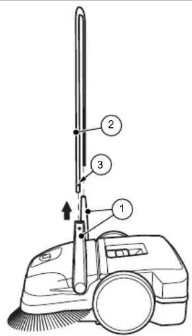
natural_image
Technical line drawing of a mechanical device with no visible text or symbolsJoon. 5: Hoidmisasend
Joon. 6: Seadme kandmine
Joon. 9: Külgmiste harjade körguse reguleerimine
Joon. 13: Juhtraua mahamonteerimine (SWP 475)
Joon. 14: Juhtraja mahamonteerimine (SWP 577)
natural_image
Technical line drawing of a mechanical device with no visible text or symbols
Consequences possibles
5.4 Stockage / conservation
NOTA
natural_image
Technical line drawing of a mechanical device with no visible text or symbols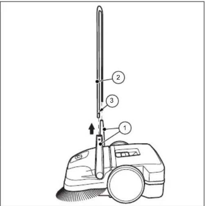
natural_image
Technical line drawing of a mechanical device with no visible text or symbolsAfb. 7: Handvatmontage (SWP 475)
Fig. 1: Komponentoversikt 1
Fig. 2: Komponentoversikt 2
| Pos.-nr. Komponent |
| 11 Feievalser til fint smuss |
| 12 Skråhjul |
| 13 Feieleppe |
| 14 Feieplate |
| 15 Typeskilt (SWP 475) |
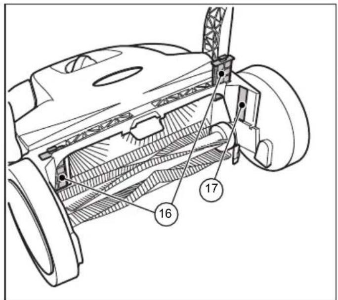
Fig. 3: Komponentoversikt 3
| Pos.-nr. Komponent |
| 16 Støvfilter (SWP 577) |
| 17 Typeskilt (SWP 577) |
natural_image
Technical line drawing of a mechanical device with no visible text or symbols8.1 Tabell over feil
Feil Årsak Botemiddel
Fig. 12: Å ta ut støvfi ltre
natural_image
Technical line drawing of a mechanical device with no visible text or symbols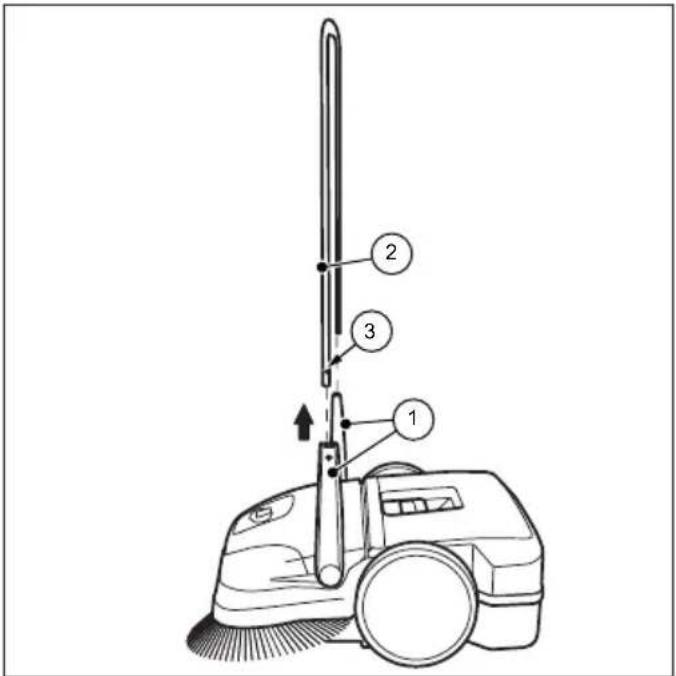
9.4 Alinhar as cerdas....182
natural_image
Technical line drawing of a mechanical device with no visible text or symbolsFig. 10: Ajuste do fi xador
Varredura de bordas e esquinas
Fig. 11: Evvaziar o recipiente de material varrido
9.4 Alinhar as cerdas

AVISO
natural_image
Technical line drawing of a mechanical device with no visible text or symbols10.2 Källsortering....212
1. Allmänt
natural_image
Technical line drawing of a mechanical device with no visible text or symbolsBild 12: Ta bort dammfi ltret
natural_image
Technical line drawing of a mechanical device with no visible text or symbols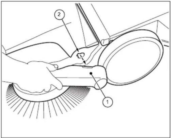
EN • The content and images in this User Manual were produced expressly for STIGA SpA and are protected by copyright – any unauthorised reproduction or modification to the document, either partially or in full, is prohibited.
Type: ....
Sweeper Hand Push
-s/n -Art.N