EWLS240JSS - Computer cooling system DAIKIN - Free user manual and instructions
Find the device manual for free EWLS240JSS DAIKIN in PDF.
| Product Type | Water chiller for computer hardware cooling |
| Brand | Daikin |
| Model | EWLS240JSS |
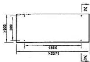
| Dimensions (H x W x D) | 1020 x 913 x 2726 mm |
| Unit weight | 1372 kg |
| Operating weight | 1409 kg |
| Power supply | Three-phase 400 V, 50 Hz, ±10% |
| Possible refrigerants | R134a (GWP 1430), R513A (GWP 572), R1234ze(E) (GWP 7) |
| Water temperature range | Operation with glycol possible down to -10°C at the evaporator |
| Chilled water inlet/outlet connection | 3 inches |
| Liquid line connection (remote condenser) | 1 3/8 inch |
| Gas discharge line connection (remote condenser) | 2 1/2 inches |
| Evaporator water flow rate | Minimum 357 l/min, maximum 1428 l/min (depending on model) |
| Max. service pressure water circuit | 10 bar |
| Main functions | Cooling and heating (heat pump) |
| Available options | BMS (Modbus, BACnet, LON), silent operation, high temperature kit, glycol |
| Included accessories | Filter kit (1 mm holes), Victaulic connections, refrigerant charge label |
| Safety | Relief valves (15.5 and 23.5 bar), flow switch, emergency stop, optional leak detector |
| Installation | Indoor only, on concrete base, with anti-vibration mounts |
| Maintenance | Periodic leak check, draining, filter replacement, refrigeration circuit maintenance by qualified personnel |
| Repairability | Spare parts available from Daikin dealer |
| Disposal | In compliance with local regulations: recycling of metals, plastics, electronics, oil and batteries |
Frequently Asked Questions - EWLS240JSS DAIKIN
User questions about EWLS240JSS DAIKIN
0 question about this device. Answer the ones you know or ask your own.
Ask a new question about this device
Download the instructions for your Computer cooling system in PDF format for free! Find your manual EWLS240JSS - DAIKIN and take your electronic device back in hand. On this page are published all the documents necessary for the use of your device. EWLS240JSS by DAIKIN.
USER MANUAL EWLS240JSS DAIKIN
| REV | 02 |
| Date | January 2021 |
| Supersedes | D-EIMWC01008-16EU |
Installation, Operation and Maintenance Manual
D-EIMWC01008-16 02EU
English language: Original instructions
All other language: Translation of the Original instructions
Water-cooled screw chillers
EWWD120J-SS ~ EWWD280J-SS
EWWH090J-SS ~ EWWH200J-SS
EWWS120J-SS ~ EWWS270J-SS
Condenserless water-cooled screw chillers
EWLD110J-SS EWLD265J-SS
EWLH80J-SS EWLH190J-SS
EWLS110J-SS EWLS270J-SS
Refrigerant: R-134a, R1234ze, R513A

| English 2 |
| Deutsch 20 |
| Français 38 |
| Nederlands 57 |
| Espanol 75 |
| Italiano 93 |
| Éλληνικά 111 |
| Português 129 |
| Yücckni 147 |
| Polski 165 |
This manual is an important supporting document for qualified personnel, but it is not intended to replace such personnel.
EWWD120J-SS 280J-SS
EWWH090J-SS 200J-SS
EWWS120J-SS 270J-SS
EWLD110J-SS ~ 265J-SS
EWLH80J-SS ~ 190J-SS
EWLS110J-SS ~ 270J-SS
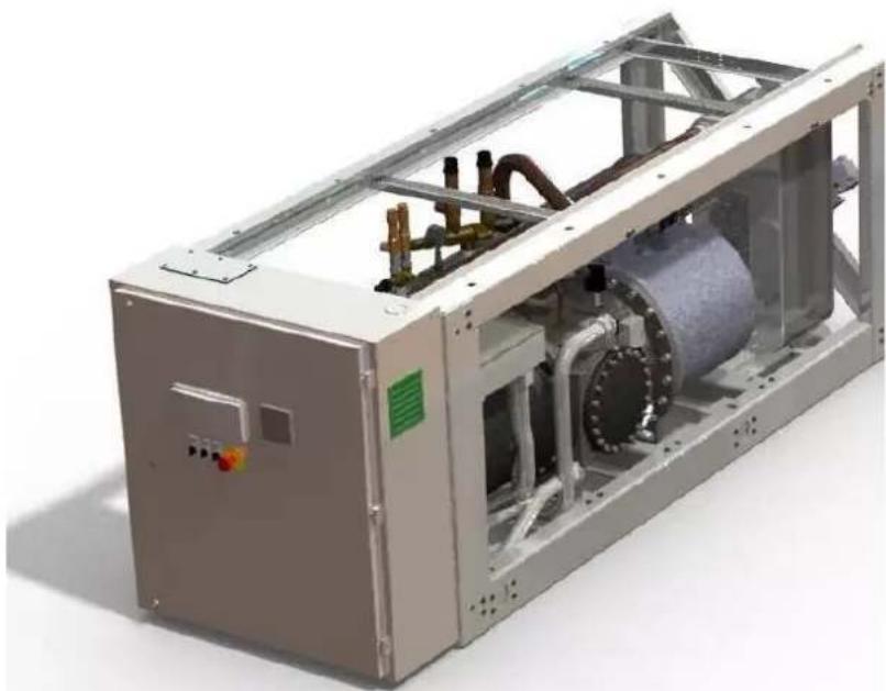
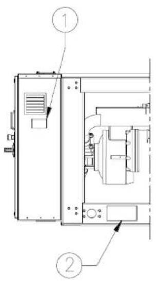
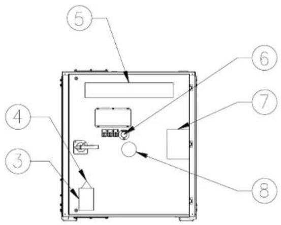
Label Identification
| 1 – Unit nameplate data | 5 – Manufacturer's logo |
| 2 – Lifting instructions | 6 – Emergency stop |
| 3 – Hazardous Voltage warning | 7 – Non-flammable gas symbol |
| 4 – Electrical hazard symbol | 8 – Gas type |
CONTENTS
- INTRODUCTION 5
1.1. Technical specifications.. 5
1.2. Electrical specifications 5
1.3. Options and features 6
1.4. Standard supplied accessories 6
- OPERATION RANGE 6
- MAIN COMPONENTS & CIRCUIT DIAGRAM 7
- SELECTION OF LOCATION 8
- INSPECTING AND HANDLING THE UNIT 8
- UNPACKING AND PLACING THE UNIT 8
- IMPORTANT INFORMATION REGARDING THE REFRIGERANTS USED 9
7.1. Pressure/temperature table 9
- INSTALLATION 10
8.1. Information about installation of systems with R134a and R513A 10
8.2. Additional guidelines for safe use of R134a and R513A 10
8.3. Physical characteristics of refrigerant R1234ze (E). 10
8.4. Information about installation of systems with R1234ze 10
8.5. Additional guidelines for safe use of R1234ze(E) for equipment located in the open air. 10
8.6. Additional guidelines for safe use of R1234ze(E) for equipment located in a machinery room 10
- MAINTENANCE 11
9.1. Routine maintenance for R1234ze 11
10.1. Precautions when handling piping 12
10.2. Leak test and vacuum drying 12
10.3. Charging the unit 12
-
PREPARING, CHECKING AND CONNECTING THE WATER CIRCUIT 13
-
WATER CHARGE, FLOW AND QUALITY 14
- PIPING INSULATION 14
- DISCHARGE FROM PRESSURE RELIEF DEVICES... 15
- FIELD WIRING 15
15.1. Parts table 15
15.2. Power circuit and cable requirements 15
15.3. Connection of the water-cooled water chiller power supply 15
15.4. Interconnection cables.. 15
15.5. Periodic obligatory checks and starting up of appliances under pressure 15
15.6. Disposal 15
- BEFORE STARTING 16
- WIRING DIAGRAMS 17
- FACTORY AND FIELD CHARGED UNITS INSTRUCTIONS 18
Thank you for purchasing this Daikin air conditioner.

READ THIS MANUAL ATTENTIVELY BEFORE STARTING UP THE UNIT. DO NOT THROW IT AWAY. KEEP IT IN YOUR FILES FOR FUTURE REFERENCE.
IMPROPER INSTALLATION OR ATTACHEMENT OF EQUIPMENT OR ACCESSORIES COULD RESULT IN ELECTRIC SHOCK, SHORT CIRCUIT, LEAKS, FIRE, OR OTHER DAMAGE TO THE EQUIPMENT. BE SURE TO USE ONLY ACCESSORIES MADE BY DAIKIN WHICH ARE SPECIFICALLY DESIGNED FOR USE WITH THE EQUIPMENT AND HAVE THEM INSTALLED BY A PROFESSIONAL.
IF UNSURE OF INSTALLATION PROCEDURES OR USE, ALWAYS CONTACT YOUR DAIKIN DEALER FOR ADVICE AND INFORMATION.
1. INTRODUCTION
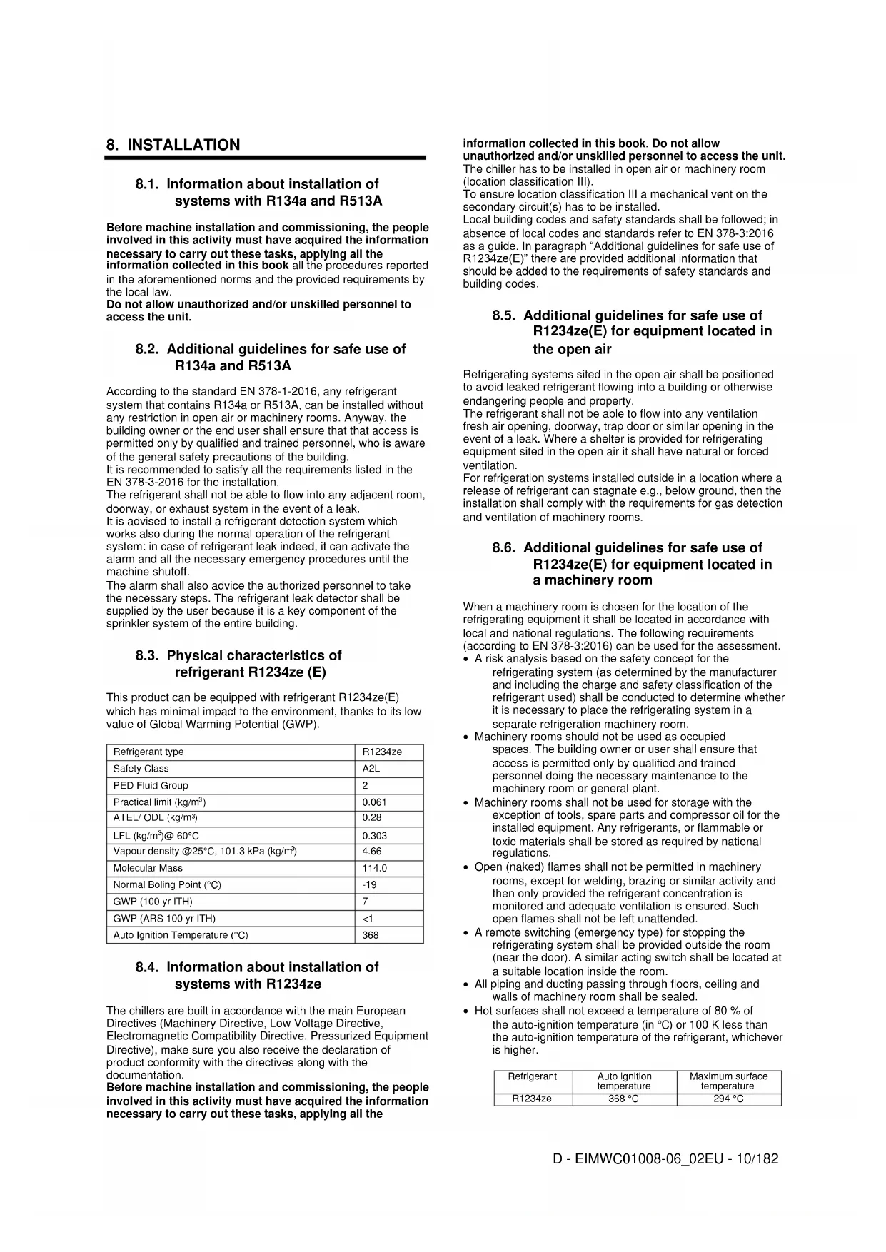
The Daikin EWWD J-EWLDJ-EWWH J-EWLH J-EWWS J- EWLS J J packaged water-cooled water chillers are designed for indoor installation and used for cooling and heating applications. The EWWD J-EWLD J units are available in 16 standard sizes and for their nominal cooling capacities see tables. The EWWH J - EWLH J - EWWS J - EWLS J units are available in 7 standard sizes and for their nominal cooling capacities see tables.
The present installation manual describes the procedures for unpacking, installing, and connecting the EWWD J-EWLD J units.
1.1. Technical specifications (1)
| Model EWWD J | 120 | 140 | 150 | 180 | 210 |
| Dimensions HxWxL (mm) | 1020x913x2681 | ||||
| Weight | |||||
| Unit weight (Kg) | 1177 | 1233 | 1334 | 1366 | 1416 |
| Operation weight (Kg) | 1211 | 1276 | 1378 | 1415 | 1473 |
| Connections | |||||
| Chilled water inlet/outlet' (inch) | 3" | ||||
| Condenser water inlet/outlet' (inch) | 2 1/2" | 4" | |||
| Model EWWD J | 250 | 280 |
| Dimensions HxWxL (mm) | 1020x913x2681 | |
| Weight | ||
| Unit weight (Kg) | 1600 | 1607 |
| Operation weight (Kg) | 1663 | 1675 |
| Connections | ||
| Chilled water inlet/outlet® (inch) | 3" | |
| Condenser water inlet/outlet® (inch) | 4" | |
| Model EWWH J | 090 | 110 | 120 | 130 | 150 |
| Dimensions HxWxL (mm) | 1020x913x2681 | ||||
| Weight | |||||
| Unit weight (Kg) | 1177 | 1233 | 1334 | 1366 | 1416 |
| Operation weight (Kg) | 1211 | 1276 | 1378 | 1415 | 1473 |
| Connections | |||||
| Chilled water inlet/outlet" (inch) | 3" | ||||
| Condenser water inlet/outlet" (inch) | 2 1⁄2" | 4" | |||
| Model EWWH J | 180 | 200 |
| Dimensions HxWxL (mm) | 1020x913x2681 | |
| Weight | ||
| Unit weight (Kg) | 1600 | 1607 |
| Operation weight (Kg) | 1663 | 1675 |
| Connections | ||
| Chilled water inlet/outlet(inch) | 3" | |
| Condenser water inlet/outlet(inch) | 4" | |
| Model EWWS J | 120 | 140 | 150 | 180 | 210 |
| Dimensions HxWxL (mm) | 1020x913x2681 | ||||
| Weight | |||||
| Unit weight (Kg) | 1177 | 1233 | 1334 | 1366 | 1416 |
| Operation weight (Kg) | 1211 | 1276 | 1378 | 1415 | 1473 |
| Connections | |||||
| Chilled water inlet/outlet (inch) | 3" | ||||
| Condenser water inlet/outlet (inch) | 2 1/2" | 4" | |||
| Model EWWS J | 240 | 270 | |
| Dimensions HxWxL (mm) | 1020x913x2681 | ||
| Weight | |||
| Unit weight (Kg) | 1600 | 1607 | |
| Operation weight (Kg) | 1663 | 1675 | |
| Connections | |||
| Chilled water inlet/outlet (inch) | 3" | ||
| Condenser water inlet/outlet (inch) | 4" | ||
| Model EWLD J | 110 | 130 | 145 | 165 | 195 |
| Dimensions HxWxL (mm) | 1020x913x2726 | ||||
| Weight | |||||
| Unit weight (Kg) | 1086 | 1101 | 1169 | 1164 | 1236 |
| Operation weight (Kg) | 1090 | 1114 | 1183 | 1183 | 1263 |
| Connections | |||||
| Chilled water inlet/outlet2 (inch) | 3" | ||||
| Liquid line inlet connection1 (inch) | 1 3/8" | ||||
| Gas discharge line connection2 (inch) | 2 1/2" | ||||
| Model EWLD J | 235 | 265 |
| Dimensions HxWxL (mm) | 1020x913x2726 | |
| Weight | ||
| Unit weight (Kg) | 1372 | 1375 |
| Operation weight (Kg) | 1409 | 1410 |
| Connections | ||
| Chilled water inlet/outleta (inch) | 3° | |
| Liquid line inlet connectionb (inch) | 1 3/8" | |
| Gas discharge line connectionb (inch) | 2 1/2" | |
| Model EWLH J | 80 | 100 | 110 | 130 | 140 |
| Dimensions HxWxL (mm) | 1020x913x2726 | ||||
| Weight | |||||
| Unit weight (Kg) | 1086 | 1101 | 1169 | 1164 | 1236 |
| Operation weight (Kg) | 1090 | 1114 | 1183 | 1183 | 1263 |
| Connections | |||||
| Chilled water inlet/outlet1 (inch) | 3" | ||||
| Liquid line inlet connection1 (inch) | 1 3/8" | ||||
| Gas discharge line connection2 (inch) | 2 1/2" | ||||
| Model EWLH J | 170 | 190 | |
| Dimensions HxWxL (mm) | 1020x913x2726 | ||
| Weight | |||
| Unit weight | (Kg) | 1372 | 1375 |
| Operation weight (Kg) | 1409 | 1410 | |
| Connections | |||
| Chilled water inlet/outlet3 (inch) | 3° | ||
| Liquid line inlet connection2 | (inch) | 1 3/8" | |
| Gas discharge line connection3 | (inch) | 2 1/2" | |
| Model EWLS J | 110 | 130 | 150 | 170 | 200 |
| Dimensions HxWxL (mm) | 1020x913x2726 | ||||
| Weight | |||||
| Unit weight (Kg) | 1086 | 1101 | 1169 | 1164 | 1236 |
| Operation weight (Kg) | 1090 | 1114 | 1183 | 1183 | 1283 |
| Connections | |||||
| Chilled water inlet/outlet3 (inch) | 3" | ||||
| Liquid line inlet connection4 (inch) | 1 3/8" | ||||
| Gas discharge line connection2 (inch) | 2 1/2" | ||||
| Model EWLS J | 240 | 270 |
| Dimensions HxWxL (mm) | 1020x913x2726 | |
| Weight | ||
| Unit weight (Kg) | 1372 | 1375 |
| Operation weight (Kg) | 1409 | 1410 |
| Connections | ||
| Chilled water inlet/outlet1 (inch) | 3" | |
| Liquid line inlet connection1 (inch) | 1 3/8" | |
| Gas discharge line connection2 (inch) | 2 1/2" | |
1.2. Electrical specifications (1)
| Model EWWD J | 120~280 |
| Model EWLD J | 110~265 |
| Model EWWH J | 090~200 |
| Model EWLH J | 080~190 |
| Model EWWS J | 120~270 |
| Model EWLS J | 110~270 |
| Power circuit | |
| Phase | 3~ |
| Frequency (Hz) | 50 |
| Voltage (V) | 400 |
| Voltage tolerance (%) | ±10 |
1.3. Options and features (1)
Options
- Ampere and voltmeter
- Dual pressure relief valve on the condenser
Low noise operation
BMS-Connection (MODBUS, BACNET, LON)
High temperature kit (only for EWWH J and EWLH J)
Features
- Glycol application for leaving evaporator water temperature down to -10^ (only for EWWD-EWLDEWWS-EWLS)
-
Sight glass with moisture indication
Voltage free contacts -
general operation/pump contact
-
alarm
-
Changeable voltage free contacts
condenser pump -
Changeable remote inputs
remote start/stop
- dual setpoint
- enable/disable capacity limitation
- Changeable analog input
- Setpoint override 4/20 mA
- Multiple language selection
1.4. Standard supplied accessories
- Filter kit for installation in front of the evaporator water inlet
2. OPERATION RANGE
EWWD J- EWLD J
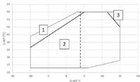
- Operation with Glycol - Fixed minimum capacity at 100%
- Operation with Glycol (below 4^ Evap LWT)
- Some units could work partially in this area
EWWH J- EWLH J
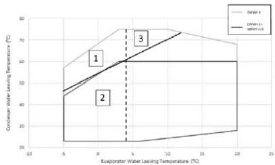
- Operation with Glycol - Fixed minimum capacity at 100%
- Operation with Glycol (below 4^ Evap LWT)
- Operation with fixed minimum capacity at 100%
EWWS J- EWLS J
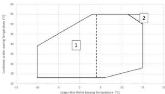
- Operation with Glycol (below 4^ Evap LWT)
- Some units could work partially in this area
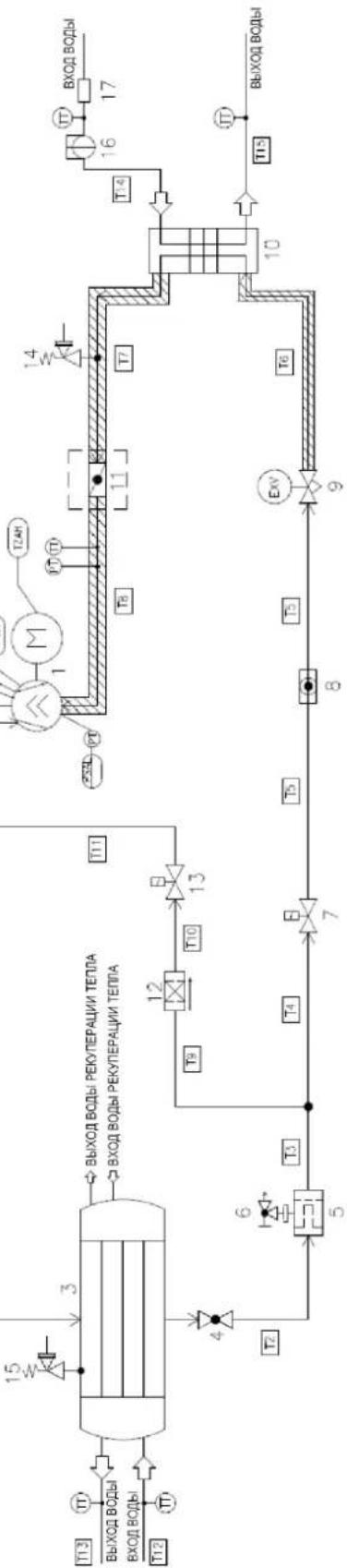
3. MAIN COMPONENTS & CIRCUIT DIAGRAM
| 9 | Expansion valve |
| 10 | Evaporator |
| 11 | Shut off valve |
| 12 | Filter |
| 13 | Solenoid valve |
| 14 | Pressure Relief valve 15,5bar |
| 15 | Pressure Relief valve 23,5bar |
| 16 | Flow Switch |
| 17 | Filter |
| Equipment | |
| 1 | Compressor |
| 2 | Shut off valve |
| 3 | Condenser |
| 4 | Shut off valve |
| 5 | Filter drier |
| 6 | Shut off valve (charge valve) |
| 7 | Solenoid valve |
| 8 | Liquid indicator |
| Control equipment | |
| PZH | High Pressure Switch 21,0bar |
| PT | Pressure Transducer |
| TT | Temperature Transducer |
| TZAH | High Temperature Switch |
| TZAH | Low Pressure Limiter |
ATTENTION:
For the units EWLD/EWLH/EWLS the
Letter L means that the unit is condenserless.
Condeser (3) is not present.

4. SELECTION OF LOCATION
The units are designed for indoor installation and should be installed in a location that meets the following requirements:
- The foundation is strong enough to support the weight of the unit and the floor is flat to prevent vibration and noise generation.
- The space around the unit is adequate for servicing.
- There is no danger of fire due to leakage of inflammable gas.
- Select the location of the unit in such a way that the sound generated by to the unit does not disturb anyone.
- Ensure that water cannot cause any damage to the location in case it drips out the unit.
NOTE Pull-down operation is restricted to one hour maximum.
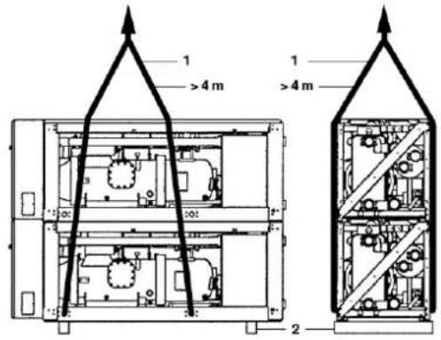
5. INSPECTING AND HANDLING THE UNIT
At delivery, the unit should be checked and any damage should be reported immediately to the carrier claims agent.
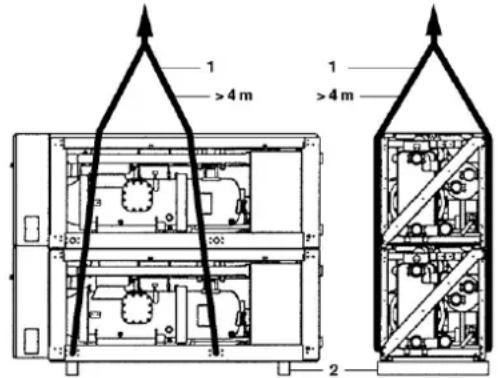
When handling the unit, take into account the following:
- List the unit preferably with a crane and belts in accordance with the instructions on the unit. The length of the ropes (1) to be used for lifting are 4m minimum each.
- The unit is shipped with wooden beams (2) under it, these have to be removed before installation.
NOTE Try to reduce the drilling in the unit to a minimum. If drilling is unpreventable, remove the iron filling thoroughly in order to prevent surface rust.
6. UNPACKING AND PLACING THE UNIT
- Remove the wooden beams from the unit.
- Install vibration mountings in case of an installation where noise and vibration might an impediment.
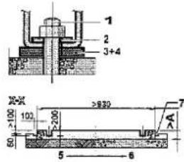
- Set the unit on a solid and level foundation.
The unit should be installed on a solid base. It is recommended to fix the unit on a concrete base with anchor bolts.
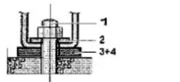
- Anchor bolt
- Washer
- Rubber plate
- Row cork or rubber sheet
- Ground
- Concrete floor
- Ditch
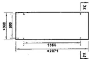
Fix anchor bolts into the concrete foundation. When finally fixing the unit by means of these anchor bolts, make sure that the washers for channel DIN434, and both field supplied rubber plates and field supplied raw cork or rubber sheets for better vibration protection, are installed as indicated.
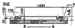
- The concrete foundation should approximately be 100mm higher than the floor level for ease of plumbing work and better drain.
| Model | A | Anchor bolt | |
| Size | Qty | ||
| EWWD120J~180J | 300 | M20x200 | 4 |
| EWLD110J~165J | |||
| EWWH090J-130J | |||
| EWLH080J-130J | |||
| EWWS120J-180J | |||
| EWLS110J-170J | |||
| EWWD210J~280J | 350 | M20x200 | 4 |
| EWLD195J~265J | |||
| EWWH150J-200J | |||
| EWLH140J-190J | |||
| EWWS200J-270J | |||
- Make sure that the foundation surface is even and flat
NOTE
The measurement tabulated is based on the fact the base is made in the ground or on a concrete floor. In case the base is made on a rigid floor, it is possible to include thickness of concrete floor in that of the base.
In case a base is made on concrete floor, make sure to provide a ditch as shown. It is important to extract drainage regardless of whether a base is made in the ground or on the concrete floor (ditch-sewerage).
- Ingredient ratio of the concrete is: cement 1, sand 2 and gravel 3. Insert iron bars of 10 at every interval of 300mm . The edge of the concrete base should be planed.
7. IMPORTANT INFORMATION REGARDING THE REFRIGERANTS USED
This product contains fluorinated greenhouse gases. Do not vent gases into the atmosphere.
| Model | EWWD J EWLD J | EWWH J EWLH J | EWWS J EWLS J |
| Refrigerant type | R134a | R1234ze | R513A |
| GWP(1) value | 1430 | 7 | 572 |
For the EWWD J, EWWH J and EWWS J unit versions the quantity is indicated on the unit name plate.
For the EWLD J, EWLH J and EWLS J unit versions, please fill the total refrigerant charge in with indelible ink on the refrigerant charge label supplied with the product. The filled-out label must be adhered inside the electric panel door.
Refrigerants R134a, R1234ze(E) and R513A are classified by European Directive 2014/68/EU as Group 2 (non-dangerous) substances as it is nonflammable at standard ambient temperature and non-toxic. Due to this, no special precautions are required for storage, transport, and handling. Daikin Applied Europe S.p.A. products comply with applicable European Directives and refer for unit design to product Standard EN378:2016 and industrial Standard ISO5149. Local authorities' approval should be verified referring to European Standard EN378 and/or ISO 5149 (where R134a and R513A are classified A1, and R1234ze(E) is classified A2L - Mildly flammable gas).
7.1. Pressure/temperature table
-R134a
| R134a Pressure/ Temperature conversion table | ||||||||
| °C | bar | °C | bar | °C | bar | °C | bar | °C |
| -15 | 1,64 | 4 | 3,38 | 23 | 6,27 | 43 | 11,01 | 62 |
| -14 | 1,71 | 5 | 3,50 | 25 | 6,46 | 44 | 11,30 | 63 |
| -13 | 1,78 | 6 | 3,62 | 26 | 6,65 | 45 | 11,60 | 64 |
| -12 | 1,85 | 7 | 3,75 | 27 | 6,85 | 46 | 11,90 | 65 |
| -11 | 1,93 | 8 | 3,88 | 28 | 7,06 | 47 | 12,21 | 66 |
| -10 | 2,01 | 9 | 4,01 | 29 | 7,27 | 48 | 12,53 | 67 |
| -9 | 2,09 | 10 | 4,15 | 30 | 7,48 | 49 | 12,85 | 68 |
| -8 | 2,17 | 11 | 4,29 | 31 | 7,70 | 50 | 13,18 | 69 |
| -7 | 2,26 | 12 | 4,43 | 32 | 7,92 | 51 | 13,51 | 70 |
| -6 | 2,34 | 13 | 4,58 | 33 | 8,15 | 52 | 13,85 | 71 |
| -5 | 2,43 | 14 | 4,73 | 34 | 8,39 | 53 | 14,20 | 72 |
| -4 | 2,53 | 15 | 4,88 | 35 | 8,63 | 54 | 14,55 | 73 |
| -3 | 2,62 | 16 | 5,04 | 36 | 8,87 | 55 | 14,91 | 74 |
| -2 | 2,72 | 17 | 5,20 | 37 | 9,12 | 56 | 15,28 | 75 |
| -1 | 2,82 | 18 | 5,37 | 38 | 9,37 | 57 | 15,65 | 76 |
| 0 | 2,93 | 19 | 5,54 | 39 | 9,63 | 58 | 16,03 | 77 |
| 1 | 3,04 | 20 | 5,72 | 40 | 9,89 | 59 | 16,42 | 78 |
| 2 | 3,15 | 21 | 5,90 | 41 | 10,16 | 60 | 16,81 | 79 |
| 3 | 3,26 | 22 | 6,08 | 42 | 10,44 | 61 | 17,22 | 80 |
- R513A
| R513A Pressure/ Temperature conversion table | |||||||||
| °C | bar | °C | bar | °C | bar | °C | bar | °C | bar |
| -15 | 1,87 | 4 | 3,73 | 23 | 6,74 | 43 | 11,58 | 62 | 18,25 |
| -14 | 1,94 | 5 | 3,85 | 25 | 6,93 | 44 | 11,88 | 63 | 18,66 |
| -13 | 2,02 | 6 | 3,98 | 26 | 7,13 | 45 | 12,18 | 64 | 19,09 |
| -12 | 2,10 | 7 | 4,11 | 27 | 7,34 | 46 | 12,49 | 65 | 19,52 |
| -11 | 2,18 | 8 | 4,25 | 28 | 7,55 | 47 | 12,80 | 66 | 19,96 |
| -10 | 2,27 | 9 | 4,39 | 29 | 7,77 | 48 | 13,12 | 67 | 20,40 |
| -9 | 2,35 | 10 | 4,53 | 30 | 7,99 | 49 | 13,44 | 68 | 20,86 |
| -8 | 2,44 | 11 | 4,68 | 31 | 8,21 | 50 | 13,77 | 69 | 21,32 |
| -7 | 2,53 | 12 | 4,83 | 32 | 8,44 | 51 | 14,11 | 70 | 21,79 |
| -6 | 2,63 | 13 | 4,98 | 33 | 8,67 | 52 | 14,46 | 71 | 22,27 |
| -5 | 2,72 | 14 | 5,14 | 34 | 8,91 | 53 | 14,81 | 72 | 22,75 |
| -4 | 2,82 | 15 | 5,30 | 35 | 9,16 | 54 | 15,16 | 73 | 23,24 |
| -3 | 2,93 | 16 | 5,47 | 36 | 9,41 | 55 | 15,52 | 74 | 23,75 |
| -2 | 3,03 | 17 | 5,64 | 37 | 9,66 | 56 | 15,89 | 75 | 24,26 |
| -1 | 3,14 | 18 | 5,81 | 38 | 9,92 | 57 | 16,27 | 76 | 24,78 |
| 0 | 3,25 | 19 | 5,99 | 39 | 10,18 | 58 | 16,65 | 77 | 25,30 |
| 1 | 3,36 | 20 | 6,17 | 40 | 10,45 | 59 | 17,04 | 78 | 25,84 |
| 2 | 3,48 | 21 | 6,35 | 41 | 10,72 | 60 | 17,43 | 79 | 26,38 |
| 3 | 3,60 | 22 | 6,54 | 42 | 11,00 | 61 | 17,84 | 80 | 26,94 |
- R1234ze (E)
| HFO-R1234ze(E) Pressure/ Temperature conversion table | |||||||||
| °C | bar | °C | bar | °C | bar | °C | bar | °C | bar |
| -15 | 1,20 | 4 | 2,50 | 23 | 4,69 | 43 | 8,31 | 62 | 13,39 |
| -14 | 1,25 | 5 | 2,59 | 25 | 4,84 | 44 | 8,53 | 63 | 13,71 |
| -13 | 1,30 | 6 | 2,69 | 26 | 4,98 | 45 | 8,76 | 64 | 14,03 |
| -12 | 1,36 | 7 | 2,78 | 27 | 5,14 | 46 | 8,99 | 65 | 14,36 |
| -11 | 1,42 | 8 | 2,88 | 28 | 5,29 | 47 | 9,23 | 66 | 14,70 |
| -10 | 1,47 | 9 | 2,98 | 29 | 5,45 | 48 | 9,47 | 67 | 15,04 |
| -9 | 1,53 | 10 | 3,08 | 30 | 5,62 | 49 | 9,72 | 68 | 15,39 |
| -8 | 1,60 | 11 | 3,19 | 31 | 5,78 | 50 | 9,97 | 69 | 15,75 |
| -7 | 1,66 | 12 | 3,30 | 32 | 5,95 | 51 | 10,23 | 70 | 16,11 |
| -6 | 1,73 | 13 | 3,41 | 33 | 6,13 | 52 | 10,49 | 71 | 16,48 |
| -5 | 1,79 | 14 | 3,52 | 34 | 6,31 | 53 | 10,76 | 72 | 16,85 |
| -4 | 1,86 | 15 | 3,64 | 35 | 6,49 | 54 | 11,03 | 73 | 17,23 |
| -3 | 1,94 | 16 | 3,76 | 36 | 6,67 | 55 | 11,30 | 74 | 17,62 |
| -2 | 2,01 | 17 | 3,88 | 37 | 6,86 | 56 | 11,58 | 75 | 18,01 |
| -1 | 2,09 | 18 | 4,01 | 38 | 7,06 | 57 | 11,87 | 76 | 18,41 |
| 0 | 2,17 | 19 | 4,14 | 39 | 7,25 | 58 | 12,16 | 77 | 18,81 |
| 1 | 2,25 | 20 | 4,27 | 40 | 7,46 | 59 | 12,46 | 78 | 19,23 |
| 2 | 2,33 | 21 | 4,41 | 41 | 7,66 | 60 | 12,76 | 79 | 19,65 |
| 3 | 2,41 | 22 | 4,55 | 42 | 7,87 | 61 | 13,07 | 80 | 20,07 |
8. INSTALLATION
8.1. Information about installation of systems with R134a and R513A
Before machine installation and commissioning, the people involved in this activity must have acquired the information necessary to carry out these tasks, applying all the information collected in this book all the procedures reported in the aforementioned norms and the provided requirements by the local law.
Do not allow unauthorized and/or unskilled personnel to access the unit.
8.2. Additional guidelines for safe use of R134a and R513A
According to the standard EN 378-1-2016, any refrigerant system that contains R134a or R513A, can be installed without any restriction in open air or machinery rooms. Anyway, the building owner or the end user shall ensure that that access is permitted only by qualified and trained personnel, who is aware of the general safety precautions of the building. It is recommended to satisfy all the requirements listed in the EN 378-3-2016 for the installation.
The refrigerant shall not be able to flow into any adjacent room, doorway, or exhaust system in the event of a leak.
It is advised to install a refrigerant detection system which works also during the normal operation of the refrigerant system: in case of refrigerant leak indeed, it can activate the alarm and all the necessary emergency procedures until the machine shutoff.
The alarm shall also advice the authorized personnel to take the necessary steps. The refrigerant leak detector shall be supplied by the user because it is a key component of the sprinkler system of the entire building.
8.3. Physical characteristics of refrigerant R1234ze (E)
This product can be equipped with refrigerant R1234ze(E) which has minimal impact to the environment, thanks to its low value of Global Warming Potential (GWP).
| Refrigerant type | R1234ze |
| Safety Class | A2L |
| PED Fluid Group | 2 |
| Practical limit \( (kg/m^3) \) | 0.061 |
| ATEL/ ODL \( (kg/m^3) \) | 0.28 |
| LFL \( (kg/m^3)@60°C \) | 0.303 |
| Vapour density @25°C, 101.3 kPa \( (kg/m^3) \) | 4.66 |
| Molecular Mass | 114.0 |
| Normal Boling Point (°C) | -19 |
| GWP (100 yr ITH) | 7 |
| GWP (ARS 100 yr ITH) | <1 |
| Auto Ignition Temperature (°C) | 368 |
8.4. Information about installation of systems with R1234ze
The chillers are built in accordance with the main European Directives (Machinery Directive, Low Voltage Directive, Electromagnetic Compatibility Directive, Pressurized Equipment Directive), make sure you also receive the declaration of product conformity with the directives along with the documentation.
Before machine installation and commissioning, the people involved in this activity must have acquired the information necessary to carry out these tasks, applying all the
information collected in this book. Do not allow unauthorized and/or unskilled personnel to access the unit.
The chiller has to be installed in open air or machinery room (location classification III).
To ensure location classification III a mechanical vent on the secondary circuit(s) has to be installed.
Local building codes and safety standards shall be followed; in absence of local codes and standards refer to EN 378-3:2016 as a guide. In paragraph "Additional guidelines for safe use of R1234ze(E)" there are provided additional information that should be added to the requirements of safety standards and building codes.
8.5. Additional guidelines for safe use of R1234ze(E) for equipment located in the open air
Refrigerating systems sited in the open air shall be positioned to avoid leaked refrigerant flowing into a building or otherwise endangering people and property.
The refrigerant shall not be able to flow into any ventilation fresh air opening, doorway, trap door or similar opening in the event of a leak. Where a shelter is provided for refrigerating equipment sited in the open air it shall have natural or forced ventilation.
For refrigeration systems installed outside in a location where a release of refrigerant can stagnate e.g., below ground, then the installation shall comply with the requirements for gas detection and ventilation of machinery rooms.
8.6. Additional guidelines for safe use of R1234ze(E) for equipment located in a machinery room
When a machinery room is chosen for the location of the refrigerating equipment it shall be located in accordance with local and national regulations. The following requirements (according to EN 378-3:2016) can be used for the assessment.
- A risk analysis based on the safety concept for the refrigerating system (as determined by the manufacturer and including the charge and safety classification of the refrigerant used) shall be conducted to determine whether it is necessary to place the refrigerating system in a separate refrigeration machinery room.
- Machinery rooms should not be used as occupied spaces. The building owner or user shall ensure that access is permitted only by qualified and trained personnel doing the necessary maintenance to the machinery room or general plant.
- Machinery rooms shall not be used for storage with the exception of tools, spare parts and compressor oil for the installed equipment. Any refrigerants, or flammable or toxic materials shall be stored as required by national regulations.
- Open (naked) flames shall not be permitted in machinery rooms, except for welding, brazing or similar activity and then only provided the refrigerant concentration is monitored and adequate ventilation is ensured. Such open flames shall not be left unattended.
- A remote switching (emergency type) for stopping the refrigerating system shall be provided outside the room (near the door). A similar acting switch shall be located at a suitable location inside the room.
- All piping and ducting passing through floors, ceiling and walls of machinery room shall be sealed.
- Hot surfaces shall not exceed a temperature of 80% of the auto-ignition temperature (in ^ ) or 100K less than the auto-ignition temperature of the refrigerant, whichever is higher.
| Refrigerant | Auto ignition temperature | Maximum surface temperature |
| R1234ze | 368 °C | 294 °C |
- Machinery rooms shall have doors opening outward and sufficient in number to ensure freedom for persons to escape in an emergency; the doors shall be tight fitting, self-closing and so designed that they can be opened from inside (antipanic system).
- Special machinery rooms where the refrigerant charge is above the practical limit for the volume of the room shall have a door that either opens directly to the outside air or through a dedicated vestibule equipped with self-closing, tight-fitting doors.
- The ventilation of machinery rooms shall be sufficient both for normal operating conditions and emergencies.
- Ventilation for normal operating conditions shall be in accordance with national regulations.
- The emergency mechanical ventilation system shall be activated by a detector(s), located in the machinery room.
-
This ventilation system shall be:
-
independent of any other ventilation system on the site.
-
provided with two independent emergency controls one located outside the machinery room, and the other inside.
-
The emergency exhaust ventilation fan shall:
-
Be either in the air flow with the motor outside the airflow or rated for hazardous areas (according to the assessment).
- Be located to avoid pressurization of the exhaust ductwork in the machinery room.
- Not cause sparks to occur if it contacts the duct material.
Airflow of the emergency mechanical ventilation shall be at least
$$ V = 0, 0 1 4 \times m ^ {2 / 3} $$
where
V is the air flow rate in m^3 /s
m is the mass of refrigerant charge, in kg, in the refrigerating system with the largest charge, any part of which is located in the machinery room;
0,014 is a conversion factor.
-
Mechanical ventilation shall be operated continuously or shall be switched on by the detector.
-
Detector shall automatically activate an alarm, start mechanical ventilation, and stop the system when it triggers.
- The location of detectors shall be chosen in relation to the refrigerant and they shall be located where the refrigerant from the leak will concentrate.
- The positioning of the detector shall be done with due consideration of local airflow patterns, accounting for location sources of ventilation and louvers. Consideration shall also be given to the possibility of mechanical damage or contamination.
- At least one detector shall be installed in each machinery room or the occupied space being considered and/or at the lowest underground room for refrigerants heavier than air and at the highest point for refrigerants lighter than air.
- Detectors shall be continuously monitored for functioning. In the case of a detector failure, the emergency sequence should be activated as if refrigerant had been detected.
- The pre-set value for the refrigerant detector at 30^ or 0^ , whichever is more critical, shall be set to 25% of the LFL. The detector shall continue to activate at higher concentrations.
| Refrigerant | LFL | Pre-set alarm | |
| R1234ze | 0,303 kg/m3 | 0,07575 kg/m3 | 16500 ppm |
- All electrical equipment (not only the refrigerating system) shall be selected to be suitable for use in the zones identified in the risk assessment. Electrical equipment
shall be deemed to comply with the requirements if the electrical supply is isolated when the refrigerant concentration reaches 25% of the lower flammable limit or less.
- Machinery rooms or special machinery rooms shall be clearly marked as such on the entrances to the room, together with warning notices indicating that unauthorized persons shall not enter and that smoking, naked light or flames are prohibited. The notices shall also state that, in the event of an emergency, only authorized persons conversant with emergency procedures shall decide whether to enter the machinery room. Additionally, warning notices shall be displayed prohibiting unauthorized operation of the system.
- The owner / operator shall keep an updated logbook of the refrigerating system.

The optional leak detector supplied by DAE with the chiller should be used exclusively to check refrigerant leakage from the chiller itself.
9. MAINTENANCE
9.1. Routine maintenance for R1234ze
Personnel working on the electrical or the refrigeration components must be authorized, trained, and fully qualified. Maintenance and repair requiring the assistance of other skilled personnel should be carried out under the supervision of the person competent in the use of flammable refrigerants. Any person conducting servicing or maintenance on a system or associated parts of the equipment should be competent according to EN 13313.
Persons working on refrigerating systems with flammable refrigerants should have competence in safety aspects of flammable refrigerant handling supported by evidence of appropriate training.
| electrical components | Never work on any electrical components, until the general supply to the unit has been cut using the disconnect switch(es) in the control box. The frequency variators used are equipped with capacitor batteries with a discharge time of 20 minutes; after disconnecting power wait 20 minutes before opening the control box. |
| refrigerating system | The following precautions should be taken before working on the refrigerant circuit: — obtain permit for hot work (if required); — ensure that no flammable materials are stored in the work area and that no ignition sources are present anywhere in the work area; — ensure that suitable fire extinguishing equipment is available; — ensure that the work area is properly ventilated before working on the refrigerant circuit or before welding, brazing or soldering work; — ensure that the leak detection equipment being used is non-sparking, adequately sealed or intrinsically safe; — ensure that all maintenance staff have been instructed. The following procedure should be followed before working on the refrigerant circuit: 1. remove refrigerant (specify the residual pressure); 2. purge circuit with inert gas (e.g., nitrogen); 3. evacuate to a pressure of 0,3 (abs.) bar (or 0,03 MPa); 4. purge again with inert gas (e.g., nitrogen); 5. open the circuit. The area should be checked with an appropriate refrigerant detector prior to and during any hot work to make the technician aware of a potentially flammable atmosphere. |
If compressors or compressor oils are to be removed, it should be ensured that it has been evacuated to an acceptable level to ensure that there is no flammable refrigerant remaining within the lubricant.
Only refrigerant recovery equipment designed for use with flammable refrigerants should be employed.
If the national rules or regulations permit the refrigerant to be drained, this should be done safely, using a hose, for example, through which the refrigerant is discharged into the outside atmosphere in a safe area. It should be ensured that an inflammable explosive refrigerant concentration cannot occur in the vicinity of an ignition source or penetrate into a building under any circumstance.
In the case of refrigerating systems with an indirect system, the heat-transfer fluid should be checked for the possible presence of refrigerant. After any repair work, the safety devices, for example refrigerant detectors and mechanical ventilation systems, should be checked and the results recorded.
It should be ensured that any missing or illegible label on components of the refrigerant circuit is replaced.
Sources of ignition should not be used when searching for a refrigerant leak.

This chiller, whether with R134a, R513A or R1234ze, must be maintained by qualified technicians. Before beginning any work on the system, personnel shall assure that all security precautions have been taken.

Always protect the operating personnel with personal protective equipment appropriate for the tasks to be performed. Common individual devices are: Helmet, goggles, gloves, caps, safety shoes. Additional individual and group protective equipment should be adopted after an adequate analysis of the specific risks in the area of relevance, according to the activities to be performed.
This product is factory charged with N
The units are equipped with a refrigerant inlet (discharge side) and a refrigerant outlet (liquid side) for the connection to a remote condenser. This circuit must be provided by a licensed technician and must comply with all relevant European and national regulations.
10.1. Precautions when handling piping

If air or dirt gets in the water circuit, problems may occur. Therefore, always take into account the following when connecting the water circuit:
- Use clean pipes only.
- Hold the pipe end downwards when removing burrs.
- Cover the pipe end when inserting it through a wall so that no dust and dirt enter.
The discharge and liquid line must be welded directly to the remote condenser piping. For use of the correct pipe diameter see table of Technical specifications.

Make sure the pipes are filled with _2 during welding in order to protect the pipes against soot. There should be no blockage (stop valve, solenoid valve) between the remote condenser and the provided liquid injection of the compressor.
10.2. Leak test and vacuum drying
The units were checked for leaks by the manufacturer. After connection of the piping, a leak test must be performed and the air in the refrigerant piping must be evacuated to a value of 4 mbars absolute by means of a vacuum pump.

Do not purge the air with refrigerants. Use a vacuum pump to vacuum the installation.
10.3. Charging the unit
- Perform an integral pre-start inspection like explained in "BEFORE STARTING".

Carefully perform all required procedures like explained in chapters from which is referred to in chapter "BEFORE STARTING", but do not start the unit.
It is also necessary to read the operation manual delivered with the unit. This will contribute to understand the operation of the unit and its electronic controller.
Pre-charge of refrigerant without operation of the unit
-
Use the 1/4" SAE Flare stop valve on the filter drier to pre-charge the unit with the complete calculated pre-charge. Do not operate the compressor for pre-charging, to avoid compressor damage!
-
After completion of procedure step 2, perform an "initial start" test:
3.1. Start the compressor and wait for the compressor to go through the star/delta. Carefully check during start-up:
- that compressor is not producing any abnormal noise or vibration:
- that high pressure rises, and low pressure drops within 10 seconds after to evaluate if the compressor is not operating in reverse due to wrong wiring;
that no safeties are activated.
3.2. Stop the compressor after 10 seconds.
Fine-tuning of refrigerant charge while unit is in operation
- Use the 1/4" SAE Flare valve on the suction for fine-tuning of the refrigerant charge and make sure to charge the refrigerant in its liquid state.
4.1. For fine-tuning of the refrigerant charge, the compressor must operate at full load (100%) .
4.2. Verify the superheat and subcooling:
- superheat must be between 3 and 8K
- subcooling must be between 3 and 8K
4.3. Verify the oil sight glass. Level must be within the sight glass.
4.4. Verify the liquid line sight glass. It should be sealed and not indicate moisture in the refrigerant.
4.5. As long as the liquid-line sight glass is not sailed, add refrigerant in steps of 1Kg and wait until the unit runs in stable conditions. Repeat the complete procedure step 4 until the liquid line sight glass is sealed. The unit must have the time to stabilize which means that this charging has to be done in a smooth way.
- Note down the superheat and subcooling for future reference.
- Fill out the total refrigerant charge on the unit nameplate and on the refrigerant charge label supplied with the product.
NOTE Take care for contamination of the remote condenser in order to avoid blocking of the system. It is impossible for the manufacturer to control the contamination of the "foreign" condenser of the installer. The unit has a strict contamination level.
11. PREPARING, CHECKING AND CONNECTING THE WATER CIRCUIT
The units are equipped with a water inlet and water outlet for connection to a chiller water circuit. This circuit must be provided by a licensed technician and must comply with all relevant European and national regulations.

If air or dirt gets in the water circuit, problems may occur. Therefore, always take into account the following when connecting the water circuit:
- Use clean pipes only.
- Hold the pipe end downwards when removing burrs.
- Cover the pipe end when inserting it through a wall so that no dust and dirt enter.
1.Preparing the unit for connection to the water circuit. A box containing Victaulic couplings and a filter is delivered with the unit.
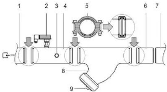
- Water inlet of the evaporator
- Flow switch
- Inlet water sensor
- Water inlet pipe containing the flow switch and the water inlet temperature sensor
- Victaul coupling
- Counter pipe
- Field water pipe circuit
- Filter
- Filter and cup
As not to damage the parts of the units during transport, the water inlet pipe with the flow switch and the water inlet temperature sensor and the water outlet pipe with the outlet water temperature sensor, are not factory mounted.
- Connecting the water inlet pipe containing the flow switch. The water inlet pipe containing the flow switch is mounted on the side of the water inlet of the evaporator(s) and is pre-insulated. Cut the tie wraps and fix the pipe with the supplied Victaulic couplings to the evaporator inlet(s).
- Connecting the water outlet pipe. The water outlet pipe is mounted on the side of the water outlet of the evaporator and is pre-insulated. Cut the tie wraps and fix the pipe(s) with the supplied Victaulic couplings to the evaporator outlet(s).
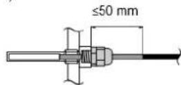
After installation of the water inlet and outlet pipes and as a general rule for other units, it is recommended to check the insertion depth of the water temperature sensors into the connection pipes prior the operation (see figure).
Connecting the filter

- The filter kit supplied with the unit must be installed in front of the evaporator water inlet by means of the supplied Victaulic couplings as shown in the figure. The filter has holes of diameter 1,0 mm and secures the evaporator against clogging.
- Improper installation of the supplied filter will result in severe damage of the equipment (freezing of the evaporator).
A field supplied blow down port for flushing fluid and accumulated material from inside the filter can be connected on the filter end cap.
- Connecting the counter pipes
- Weld the supplied counter pipes to the ends of the water circuit and connect to the unit with the provided Victaulic® couplings.
- Drain taps must be provided at all low points of the system to permit complete drainage of the circuit during maintenance or in case of shut down. The drain plug is provided to drain the condenser. When doing this, also remove the air plugs (refer to the outlook diagram).
- Air vent must be provided at all high points of the system. The vents should be located at points which are easily accessible for servicing.
- Shut-off valves should be provided at the unit so that normal servicing can be accomplished without draining the system.
- Vibration eliminators in all water piping connected to the chiller are recommended to avoid straining the piping and transmitting vibration and noise.
- For units in double circuit configuration with common leaving water control (ELWT), be sure to foresee an insertion hole for the additional water temperature sensor. Sensor and sensor holder are optional parts. The insertion hole shall be 1/4 " GAS female thread and should be located in the mixed waterflow of the chillers. Make sure that the sensor tip is in the waterflow and that you have a length of straight pipe (L) of at least 10x the pipe diameter (A) before the sensor.

Choose the position of insertion in a way that the cable length of the sensor (10m) is long enough.
12. WATER CHARGE, FLOW AND QUALITY
To assure proper operation of the unit, the water flow through the evaporator must be within the operation range as specified in the table below and a minimum water volume is required in the system.
The minimum water volume v [l] in the system must fulfil the criteria below:
$$ v > (Q / 2) x T / (C x \Delta T) $$
Q highest cooling capacity of the unit in lowest capacity step within the range of application (kW)
t antirecycling timer of unit (AREC) / 2(s) = 300 s
C specific heat capacity of the fluidum
(kJ / kg^) = 4,186kJ / kg^ for water
T temperature difference between starting and stopping of the compressor: T = a + 2b + c (for designation of a, b, and c, refer to the operation manual)
NOTE
For units in a double circuit configuration, the minimum required water volume in the system must equal the biggest required minimum volume of every individual chiller in the system.
The water quality must be in accordance with the specifications listed the table below:
| DAE Water quality requirements | Shell & tube Heat Exchanger | Brazed Plate Heat Exchanger |
| pH at \( {25}^{ \circ }\mathrm{C} \) | \( {6.8} \div {8.4} \) | 6.8~8.0 |
| Electrical conductivity at 25°C [μS/m] | < 800 | < 500 |
| Chloride Ion [mg Cl-/l] | < 150 | < 70 (HP1); < 300 (CO2) |
| Sulfate ion [mg \( {\mathrm{{SO}}}_{4}{}^{2 - }/\mathrm{l} \) ] | < 100 | < 100 |
| Alkalinity [mg CaCO3/l] | < 100 | < 200 |
| Total hardness [mg CaCO3/l] | < 200 | \( {75} \div {150} \) |
| Iron [mg Fe/l] | < 1 | < 0.2 |
| Ammonium ion [mg NH4+/l] | < 1 | < 0.5 |
| Silica [mg SiO2 / l] | < 50 | - |
| Chlorine molecular [mg Cl2/l] | < 5 | < 0.5 |
Note:
- Heat Pump unit
- Cooling Only unit

The water pressure should not exceed the maximum working pressure of 10 bar.
NOTE
Provide adequate safeguards in the water circuit to make sure that the water pressure will never exceed the maximum allowable working pressure.
13. PIPING INSULATION
The complete water circuit, inclusive all piping, must be insulated to prevent condensation and reduction of the cooling capacity.
Protect the water piping against water freezing during winter period (e.g., by using a glycol solution or heater tape).
14. DISCHARGE FROM PRESSURE RELIEF DEVICES
Discharge of the refrigerant into installation area has to be in accordance with local regulations. If required it is possible to connect a 1^ pipe to each pressure relief valve on the condenser and 1 / 2 pipe to each pressure relief valve on the evaporator.
Cross section and length of the discharge line must comply with local codes.
15. FIELD WIRING

All field wiring and components must be installed by a licensed electrician and must comply with relevant European and national regulations.
The field wiring must be carried out in accordance with the wiring diagram supplied with the unit and the instructions given below.
Be sure to use a dedicated power circuit. Never use a power supply shared by another appliance.
NOTE Verify on the wiring diagram all electrical actions mentioned below, in order to understand the operation of the unit more deeply.
15.1. Parts table
F1.2 Main fuses for the unit
L1, 2, 3 Main supply terminals
PE. Main earth terminal
S6S .. Setpoint override
FS. Flow switch
Q10 Main isolator switch
Field wiring
15.2. Power circuit and cable requirements
- The electrical power supply to the unit should be arranged so that it can be switched on or off independently of the electrical supply to other items of the plant and equipment in general.
- A power circuit must be provided for connection of the unit. This circuit must be protected with the required safety devices, i.e., a circuit breaker, a slow blow fuse on each phase and an earth leak detector. Recommended fuses are mentioned on the wiring diagram supplied with the unit.

Switch off the main isolator switch before making any connections (switch off the circuit breaker, remove or switch off the fuses).
15.3. Connection of the water-cooled water chiller power supply
- Using the appropriate cable, connect the power circuit to the L1, L2 and L3 terminals of the unit.
- Connect the earth conductor (yellow/green) to the earthing terminal PE.
15.4. Interconnection cables

A pump interlock contact must be installed in series with the contact of the flow switch(es) to prevent the unit from operating without water flow. A terminal is provided
in the switch box for the electrical connection of the interlock contact.
In both cases, all units must be equipped with an Interlock contact!
NOTE
Normally the unit will not operate if there is no flow thanks to the standard installed flow switch. But as to have a double safety, you must install the pump interlock contact in series with the contact of the flow switch. Operating the unit without flow will result in very severe damage to the unit (freezing of the evaporator).
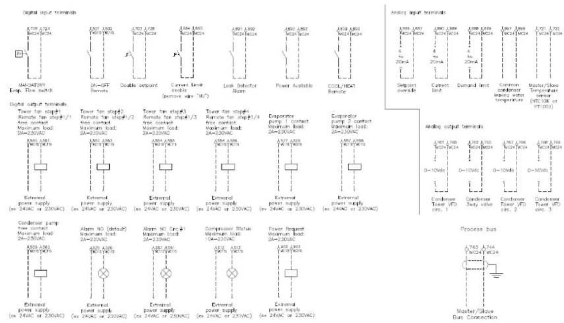
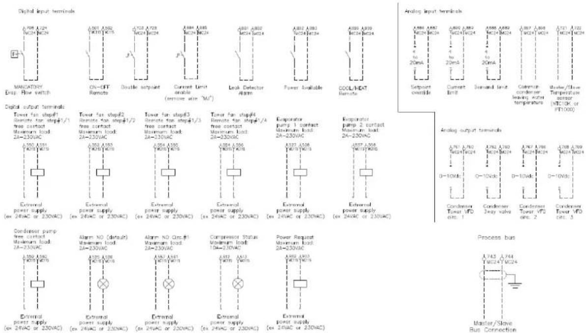
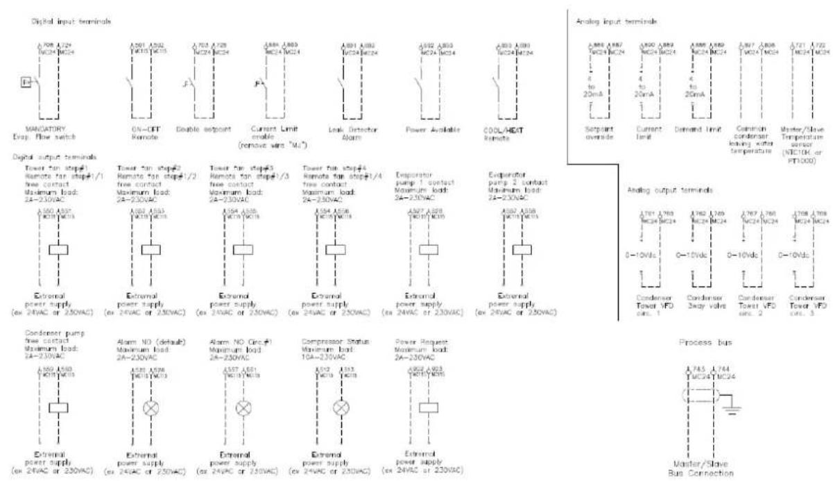
Voltage free contacts
The controller is provided with some voltage free contacts to indicate the status of the unit. These voltage free contacts can be wired as described on the wiring diagram. The maximum allowable current is 2 A.
Remote inputs
Besides the voltage free contacts, there are also possibilities to install remote inputs.
They can be installed as shown on the wiring diagram.
15.5. Periodic obligatory checks and starting up of appliances under pressure
The units are included in category III of the classification established by the European Directive 2014/68/EU (PED). For chiller belonging to this category, some local regulations require a periodic inspection by an authorized agency. Please check with your local requirements.
15.6. Disposal
The unit is made of metal, plastic, and electronic parts.
All these parts must be disposed of in accordance with the local regulations in terms of disposal.
Lead batteries must be collected and sent to specific refuse collection centres.
Oil must be collected and sent to specific refuse collection centres.
16. BEFORE STARTING

The unit should not be started, not even for a very short period of time, before the following pre-commissioning checklist is filled out completely.
| tick √ when checked | standard steps to go through before starting the unit |
| ☐ 1 | Check for external damage. |
| ☐ 2 | Open all shut-off valves. |
| ☐ 3 | Install main fuses, earth leak detector and main switch. Recommended fuses: aM according to IEC standard 269-2.Refer to the wiring diagram for size. |
| ☐ 4 | Supply the main voltage and check if it is within the allowable ±10% limits of the nameplate rating.The electrical main power supply should be arranged so, that it can be switched on or off independently of the electrical supply to other items of the plant and equipment in general.Refer to the wiring diagram, terminals L1, L2 and L3. |
| ☐ 5 | Supply water to the evaporator and verify if水流 is within the limits as given in the table under "Water charge, flow and quality". |
| ☐ 6 | The piping must be completely purged. See also chapter "Preparing, checking and connecting the water circuit". |
| ☐ 7 | Connect the pump contact(s) in series with the contact of the flow switch(es), so that the unit can only come in operation when the water pumps are running, and the water flow is sufficient. |
| ☐ 8 | Check the oil level in the compressors. |
| ☐ 9 | Install the filter kit(s) supplied with the unit in front of the evaporator(s) water inlet. |
| ☐ 10 | Check that all the water sensors are correctly fixed into the heat exchanger (see also the sticker attached to the heat exchanger). |
NOTE
It is necessary to read the operation manual delivered with the unit before operating the unit. It will contribute to understand the operation of the unit and its electronic controller.
Close all switch box doors after installation of the unit.
17. WIRING DIAGRAMS
- Wiring diagram in case of star delta starter
- Wiring diagram in case of soft starter
(Important information regarding the refrigerant used)
The refrigerant system will be charged with fluorinated greenhouse gases. Do not vent gases into the atmosphere.
-
Fill in with indelible ink the refrigerant charge label supplied with the product as following instructions:
-
the refrigerant charge for each circuit (1; 2; 3)
- the total refrigerant charge (1 + 2 + 3)
calculate the greenhouse gas emission with the following formula: GWP value of the refrigerant x Total refrigerant charge (in kg) / 1000
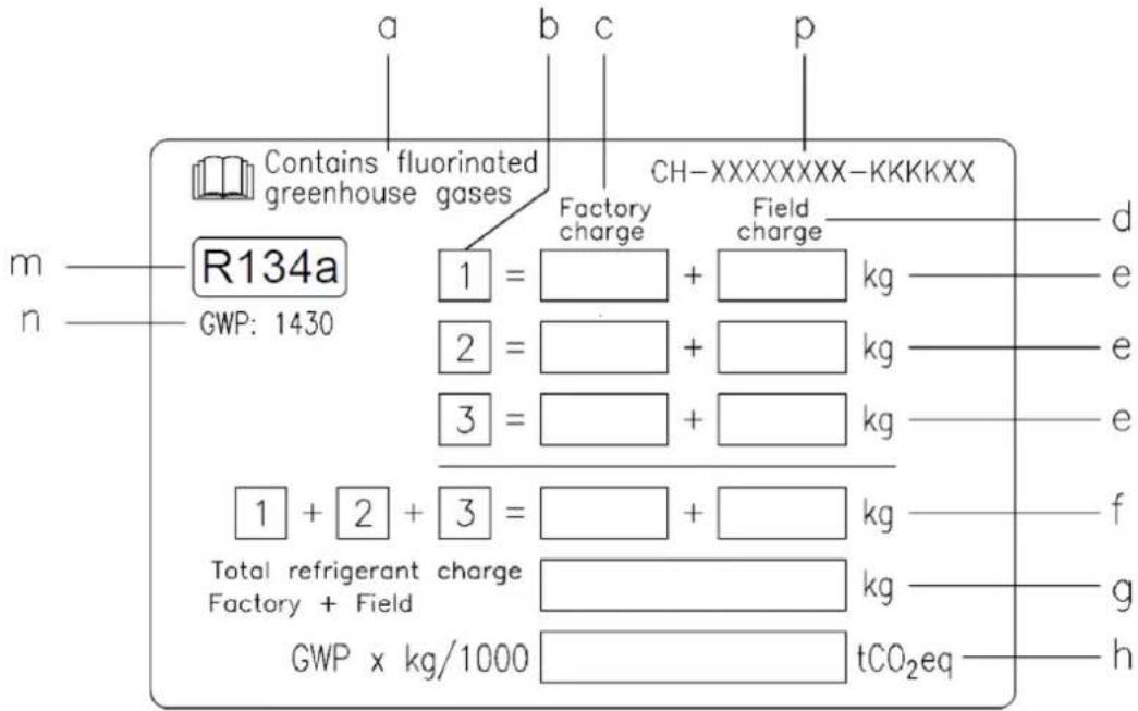
a Contains fluorinated greenhouse gases
b Circuit number
c Factory charge
d Field charge
e Refrigerant charge for each circuit (according to the number of circuits)
Total refrigerant charge
g Total refrigerant charge (Factory + Field)
h Greenhouse gas emission of the total refrigerant charge expressed as tonnes of CO_2 equivalent
m Refrigerant type
n GWP = Global Warming Potential
p Unit serial number
- The filled-out label must be adhered inside the electrical panel.
Periodical inspections for refrigerant leaks may be required depending on European or local legislation. Please contact your local dealer for more information.
NOTICE
In Europe, the greenhouse gas emission of the total refrigerant charge in the system (expressed as tonnes CO_2 equivalent) is used to
determine the maintenance intervals.
Follow the applicable legislation.
Formula to calculate the greenhouse gas emission:
GWP value of the refrigerant x Total refrigerant charge (in kg) / 1000.
Use the GWP value mentioned on the greenhouse gases label. This GWP value is based on the 4th IPCC Assessment Report. The GWP value mentioned in the manual might be outdated (i.e., based on the 3rd IPCC Assessment Report).
The present publication is drawn up by of information only and does not constitute an offer binding upon Daikin Applied Europe S.p.A.. Daikin Applied Europe S.p.A. has compiled the content of this publication to the best of its knowledge. No express or implied warranty is given for the completeness, accuracy, reliability, or fitness for particular purpose of its content, and the products and services presented therein. Specifications are subject to change without prior notice. Refer to the data communicated at the time of the order. Daikin Applied Europe S.p.A. explicitly rejects any liability for any direct or indirect damage, in the broadest sense, arising from or related to the use and/or interpretation of this publication. All content is copyrighted by Daikin Applied Europe S.p.A..
DAIKIN APPLIED EUROPE S.p.A.
EWLS110J-SS ~ 270J-SS
EWLS110J-SS ~ 270J-SS
DAIKIN APPLIED EUROPE S.p.A.
EWLS110J-SS ~ 270J-SS
DAIKIN APPLIED EUROPE S.p.A.
EWLS110J-SS ~ 270J-SS
06o3haueHne Ta6nueK
Kohdehcatop (3) orctctayet.
Kneikov ktoniognoeH MaTePnT oIIOH 9-19 MM
4. BbIBOP MECTA YCTAHOBKN
ArperaTbI npEHa3HaeHb IINyYCTaHOBKN B NOMEUeHN B MeCe,OTBeuAOJsem CNeDyIOUIM TpeBOBaHnM:
1.Фундамent,HA KOTOpBiy yCTaHABINBaEcTc arperaT,ДОПКЕн IMeTb DOCTaTOUHyI HecyIuYIO CnOCo6HoCtB IPOBHyIO NOBepxHOcTb IIN MHNIM3aUNI UyMOB IN Bn6paun.
2. Bokpyarperata DonKHO 6bItb DocTaOuHc MeCTa InayTexHueckoro 06CnyKBAHHa
3. B MecTe yCTaHOBKn OTCyTCTBye TOnaCHOCTb BO3rOpAHn, T.K. XnaDaIeHT He rOIOU.
4. BbIpaTMe MeTo yCTaHOBKn TAK, YTO6bI Wm OT pa60tbi arperata He co3dabn Heyo6cTB.
5. Y6eNTecb B TOM, yTO yTeKa BObl n3 arperata He npuHHT emy Bpea.
ПРМЕЧАН. Мкимаьнар npoДоЖNTeЛьноctь HENpepbBHO paObToI arperata coCTaBnE T OINH Yac.
5. OCMOTP AΓPERATA N OBPAUÇEHNE C HYM
O6o Bcex noBpeKdEHHx, o6hApyKeHHbIX npn nocTabke, cIeNyEt He3aMeDInTeNbHO yBeDOMt b areHTa n ppeTeH3nM nepeBO3uKa.
PpO6paueHn c aRperaTOM co6IIOaIte cneDyUoIe npabuna:
1.ДЯ NOДьEMA arperaTapeKOMeHnyETcNcNoJIb3OBAbTBcKaHnCTPONblCOrIaCHO yka3AHm HactoIeRpyKOBOID7Ba.ДИнHa KaJdIOn NOДьEMHO CTPONbl(1)doJIxHa 6bITb HeMehee4M.
2. Arperat noctabnreTcHa DepeBHHbIX 6anKax (2), KOtOpbie Heo6xOdmo ydaNtB Do MOHTaXa.
IPIPMEYAHNE. IocapaiTecb n36eRaTc CBepnHn KOpnyca arperata.Ecn 6e3 cBepnHe He o6oTuCb, TuaTeJbHO Ouchntte OTBepCTN BO n36ExaHne pXabHne.
6. PACNAKOBKA IN PA3MELEHHNE AGPERATA
- YdaJInte TpaHcnpTIpOBoUHbIe DepeBraHHbIe 6aJIK.
- PnM MOHTaKe arperata B MeCTax, rIe He DoJIxHo 6bITb Wyma n Bn5paqnn, yCTaHOBTe noXoJIoNe Bn6pOONOpbl.
- YctaHOBeTe aPerat Ha npOHyb n poBbH cyHaMeHT.
Arperat cneNyet yctaHabnBaTb Ha TbePdom OCHOBAHN. PekomeHnyetc3aKpeNTb arperat Ha FyHdAmente C nOMOu bHOAKePbIX 6oNTOB.
- Ankephb60nT
- 甲
- PeHHOBaI nnTa
- NpoknaKn np6kn n pe3nbl
- 3emn
- BetoHHbI non
7.ДрehaKaHaKaHaBaK
3aKpeHnTe aHKePbIe 60JIb b 6eToHOM fHydAmHeTe. Pered OKOHaTeJIbHO 3aTAKKOa HKePbIX 60Ib8 y6eHITcB b TOM, qTO IaM6bI DIN434, a TaKke pe3HOBIIe PNTIb IN KOPKOBIIe NpE3HOBIIe NOkNAdKn, npNo6peTaembl No MeCy t cyNkaUne dN B6pOu3OJRAU, YCTaHOBJEh, KaK NOKa3AHO BVIIwe.
BetoHbIyHdAmENTdoJxHc6bItbpnMepHoHa 100MMBbIe ypoBna nona-3TOynpocNT npOKNaKy TpyboPBOOBoN oobceNeHT rapaHTnpoBaHHbIO TBOD BODbl.
| Модаль | A | Анкерный бOLT Раимер | Кол-во |
| EWWD120J~180J | 300 | M20x200 | 4 |
| EWLD110J~165J | |||
| EWWH090J-130J | |||
| EWLH080J-130J | |||
| EWWS120J-180J | |||
| EWLS110J-170J | |||
| EWWD210J~280J | 350 | M20x200 | 4 |
| EWLD195J~265J | |||
| EWWH150J-200J | |||
| EWLH140J-190J | |||
| EWWS200J-270J |
- Y6eIITecb B TOM, YTO NOBepxHOCTb ΦyHdAmEHTa POBHAR N TROP3OHTaJIbHAJ
NPNMEUHNE. B TaBnue npBODaTc uΦpbl dIarperaTOB, yCTaHABINBaEMbIX Ha 3eMIOI INI 6eONHBI ΦyHdAMET. EcnI ΦyHdAMENT yCTpaINBaETc H a TBepdOM NONY, TOniHy nOla nPiNTb MoXHO CNOXHTb.
EcnIyHdAmeHT ycTpaBaetcHa 6eToHHOM nOHy, He 3a6yDBe yCTpOntB dpEnKaHXy KaHABky, KaN pOKa3aHO Ha pncYHke. HadeKbHn DpeHax Heo6xOdIMo o6ecNeuHT He3aBNCmO OT TORO, YcTpaBaETcNfPyHdAmeHT Ha 3emJI nn 6eToHHOM nOHy.
CoOTHOWeHHe KOMNoHErTOB DnBa 6eToHHOro FyHdAmEHTa: CEmeHT — 1 Yactb, NecOK 2 n rpaBm - 3 YacTn. Upeez kaxDbIe 300 MM FyHdAmEHT cJeDyeT YkPeNITb CTaJIbHO apMaTyPOJ 010 MM. Kpa8 SeToHHOrO OCHOBAHN Heo6XoDNMO BblpOBHrtb.
7. BAXHAR INHΦOPMAUЯ O6 ИСПОЛьЗЕМБΙX XЛАДАГERTAX
DahHoe n3dJeNne coepKHT fTopnpoBaHHbIe napHKOBblE ra3bl. He BblNyckaiTe 3TN ra3bl B aTMocpepy.
| Мо德尔 | EWWD J EWLD J | EWWH J EWLH J | EWWS J EWLS J |
| Ти пхада rentа | R134a | R1234ze | R513A |
| Пгп (1) | 1430 | 7 | 572 |
IЯarperatoB moeneEWWD J, EWWH Jn EWWS J KOJIueCTBO XnaIaIeHTa yka3aHO Ha nacnpTHo TabJnueKe.
IraeratoB TnA EWLD J, EWLH J n EWLS J 3aNwite
06uouo6bem XnaadareHTa, 3apabneHHoro B CnCTeMy,
HeCMbIbaeMbIM YepHNlAmn Ha CneuaNbHO H3TNKeTke B
KOMPNeKeTe NOCTABKn.
3aONHHeHyO 3TNKeTky Heo6XoDmO npNKNeuNb N3HyTpNi K
Dbepue 3JNEKTpucecko OuNTa.
B cooTBeCTBm n EbponeNcKoI npEeKTHBoY 2014/68/EU, XnaadareHbI R134a,R1234ze(E) n R513A oTHocraK K KaTeOpn 2 (HeonachBle BeuecTBa), NoCKOblky OHn He BocnnAmeneHJTOprn CTAndapThoN Temnepaty OkpykaioIe BO3dyx N He RaBnAOTc TOKCNbHMn. B 3Toi CB3n pXpaHeHH, TpaHCnpTnPoBKN arperata N obpaSeHH C HMI OOC6ble Mepe IpRedocTopoxHOCTNe H TeP6yIOcTc.
N3deHn KomnHn Daikin Applied Europe S.p.A. OTBeuaeT Tpe6oBaHnM COoTBeCTByOuNX DnpeKTHB EC. KoHCTpykUnn N3deHn COoTBeCTByET npOn3BODCTBeHHOMy cTAHdaptY EN 378:2016 n TexNHueckOMy cTAHdaptY ISO 5149. Ppi npOBepke pa3peHnmeCtBxI opraHOv BnactN Heo6xoDmO pykoBDCTBOBaTcB EbponeNckIM cTAHdaptOM EN 378 n (nN) ISO 5149 (coRNaCHO KOtopbIM R134a n R513A oTHocraK K KaTeOpn A1, a R1234ze(E) - K KaTeOpn A2L - yMepeHno ropouh m ra3).
7.1. Ta6nua daBneHn/TeMnepaTpybI
- R134a
R134a Ipebeodna TaBnua daBneHra/TemepaTpyb
| °C | 6ap | °C | 6ap | °C | 6ap | °C | 6ap | °C | 6ap |
| -15 | 1,64 | 4 | 3,38 | 23 | 6,27 | 43 | 11,01 | 62 | 17,62 |
| -14 | 1,71 | 5 | 3,50 | 25 | 6,46 | 44 | 11,30 | 63 | 18,04 |
| -13 | 1,78 | 6 | 3,62 | 26 | 6,65 | 45 | 11,60 | 64 | 18,46 |
| -12 | 1,85 | 7 | 3,75 | 27 | 6,85 | 46 | 11,90 | 65 | 18,89 |
| -11 | 1,93 | 8 | 3,88 | 28 | 7,06 | 47 | 12,21 | 66 | 19,33 |
| -10 | 2,01 | 9 | 4,01 | 29 | 7,27 | 48 | 12,53 | 67 | 19,78 |
| -9 | 2,09 | 10 | 4,15 | 30 | 7,48 | 49 | 12,85 | 68 | 20,23 |
| -8 | 2,17 | 11 | 4,29 | 31 | 7,70 | 50 | 13,18 | 69 | 20,69 |
| -7 | 2,26 | 12 | 4,43 | 32 | 7,92 | 51 | 13,51 | 70 | 21,16 |
| -6 | 2,34 | 13 | 4,58 | 33 | 8,15 | 52 | 13,85 | 71 | 21,64 |
| -5 | 2,43 | 14 | 4,73 | 34 | 8,39 | 53 | 14,20 | 72 | 22,13 |
| -4 | 2,53 | 15 | 4,88 | 35 | 8,63 | 54 | 14,55 | 73 | 22,62 |
| -3 | 2,62 | 16 | 5,04 | 36 | 8,87 | 55 | 14,91 | 74 | 23,12 |
| -2 | 2,72 | 17 | 5,20 | 37 | 9,12 | 56 | 15,28 | 75 | 23,63 |
| -1 | 2,82 | 18 | 5,37 | 38 | 9,37 | 57 | 15,65 | 76 | 24,15 |
| 0 | 2,93 | 19 | 5,54 | 39 | 9,63 | 58 | 16,03 | 77 | 24,68 |
| 1 | 3,04 | 20 | 5,72 | 40 | 9,89 | 59 | 16,42 | 78 | 25,22 |
| 2 | 3,15 | 21 | 5,90 | 41 | 10,16 | 60 | 16,81 | 79 | 25,77 |
| 3 | 3,26 | 22 | 6,08 | 42 | 10,44 | 61 | 17,22 | 80 | 26,32 |
- R513A
| R513A Пераовданая табида давлиения/Tемператулы | |||||||||
| °C | 6ap | °C | 6ap | °C | 6ap | °C | 6ap | °C | 6ap |
| -15 | 1,87 | 4 | 3,73 | 23 | 6,74 | 43 | 11,58 | 62 | 18,25 |
| -14 | 1,94 | 5 | 3,85 | 25 | 6,93 | 44 | 11,88 | 63 | 18,66 |
| -13 | 2,02 | 6 | 3,98 | 26 | 7,13 | 45 | 12,18 | 64 | 19,09 |
| -12 | 2,10 | 7 | 4,11 | 27 | 7,34 | 46 | 12,49 | 65 | 19,52 |
| -11 | 2,18 | 8 | 4,25 | 28 | 7,55 | 47 | 12,80 | 66 | 19,96 |
| -10 | 2,27 | 9 | 4,39 | 29 | 7,77 | 48 | 13,12 | 67 | 20,40 |
| -9 | 2,35 | 10 | 4,53 | 30 | 7,99 | 49 | 13,44 | 68 | 20,86 |
| -8 | 2,44 | 11 | 4,68 | 31 | 8,21 | 50 | 13,77 | 69 | 21,32 |
| -7 | 2,53 | 12 | 4,83 | 32 | 8,44 | 51 | 14,11 | 70 | 21,79 |
| -6 | 2,63 | 13 | 4,98 | 33 | 8,67 | 52 | 14,46 | 71 | 22,27 |
| -5 | 2,72 | 14 | 5,14 | 34 | 8,91 | 53 | 14,81 | 72 | 22,75 |
| -4 | 2,82 | 15 | 5,30 | 35 | 9,16 | 54 | 15,16 | 73 | 23,24 |
| -3 | 2,93 | 16 | 5,47 | 36 | 9,41 | 55 | 15,52 | 74 | 23,75 |
| -2 | 3,03 | 17 | 5,64 | 37 | 9,66 | 56 | 15,89 | 75 | 24,26 |
| -1 | 3,14 | 18 | 5,81 | 38 | 9,92 | 57 | 16,27 | 76 | 24,78 |
| 0 | 3,25 | 19 | 5,99 | 39 | 10,18 | 58 | 16,65 | 77 | 25,30 |
| 1 | 3,36 | 20 | 6,17 | 40 | 10,45 | 59 | 17,04 | 78 | 25,84 |
| 2 | 3,48 | 21 | 6,35 | 41 | 10,72 | 60 | 17,43 | 79 | 26,38 |
| 3 | 3,60 | 22 | 6,54 | 42 | 11,00 | 61 | 17,84 | 80 | 26,94 |
- R1234ze (E)
| HFO-R1234ze(E) Пераоведая Тампua давlenя/ТемпаТурь | |||||||||
| °C | 6ap | °C | 6ap | °C | 6ap | °C | 6ap | °C | 6ap |
| -15 | 1,20 | 4 | 2,50 | 23 | 4,69 | 43 | 8,31 | 62 | 13,39 |
| -14 | 1,25 | 5 | 2,59 | 25 | 4,84 | 44 | 8,53 | 63 | 13,71 |
| -13 | 1,30 | 6 | 2,69 | 26 | 4,98 | 45 | 8,76 | 64 | 14,03 |
| -12 | 1,36 | 7 | 2,78 | 27 | 5,14 | 46 | 8,99 | 65 | 14,36 |
| -11 | 1,42 | 8 | 2,88 | 28 | 5,29 | 47 | 9,23 | 66 | 14,70 |
| -10 | 1,47 | 9 | 2,98 | 29 | 5,45 | 48 | 9,47 | 67 | 15,04 |
| -9 | 1,53 | 10 | 3,08 | 30 | 5,62 | 49 | 9,72 | 68 | 15,39 |
| -8 | 1,60 | 11 | 3,19 | 31 | 5,78 | 50 | 9,97 | 69 | 15,75 |
| -7 | 1,66 | 12 | 3,30 | 32 | 5,95 | 51 | 10,23 | 70 | 16,11 |
| -6 | 1,73 | 13 | 3,41 | 33 | 6,13 | 52 | 10,49 | 71 | 16,48 |
| -5 | 1,79 | 14 | 3,52 | 34 | 6,31 | 53 | 10,76 | 72 | 16,85 |
| -4 | 1,86 | 15 | 3,64 | 35 | 6,49 | 54 | 11,03 | 73 | 17,23 |
| -3 | 1,94 | 16 | 3,76 | 36 | 6,67 | 55 | 11,30 | 74 | 17,62 |
| -2 | 2,01 | 17 | 3,88 | 37 | 6,86 | 56 | 11,58 | 75 | 18,01 |
| -1 | 2,09 | 18 | 4,01 | 38 | 7,06 | 57 | 11,87 | 76 | 18,41 |
| 0 | 2,17 | 19 | 4,14 | 39 | 7,25 | 58 | 12,16 | 77 | 18,81 |
| 1 | 2,25 | 20 | 4,27 | 40 | 7,46 | 59 | 12,46 | 78 | 19,23 |
| 2 | 2,33 | 21 | 4,41 | 41 | 7,66 | 60 | 12,76 | 79 | 19,65 |
| 3 | 2,41 | 22 | 4,55 | 42 | 7,87 | 61 | 13,07 | 80 | 20,07 |
8.1.Инфорmaцьо моHTаже систem c R134a n R513A
До мontаи nуcka arpera tВ 3knnyatauio nla ca, yuctbyoune B daHbIX pa60tax,doXhbl nOyHTb nΦopmaIOHO, Heo6xOIMyU dnaNX bBInONHeHn. Kpome TOrO, Heo6xOIMO npimeHaTB BCE CBeDeHn, npueDeHHbIe B HactoIeM pyKOBOpCTBe, BInONHrTb BCE npoeDpybI,yka3aHbIe B BblEo3HAueHHbIX CTAndapTxA, a TaKke coBIOJDAtB Tpe6oBaHN MeCTHO r3aKHOdaTeNbCTBa. He donyckaIte K pa6oTAM c arperatOM nua, He nMeounx Heo6xOIMbIX pa3peWeHn n (nn) KBaIIHnФkaun.
8.2.Дононтелбныуka3аня no 6e3oNaChomy nCnoJb3OBAHnR134a n R513A
COrnacho cTaHapTy EN 378-1-2016, nIO6a cnCTema
xIadaHrta, copeKaaJra R134a nnR513A, moKeT 6e3
kAnx-JIbO orpaHueHn yctHaBnBaTbCn HaOTkpblTom
Bo3dyXe nn B MaunHHom 3ane. B IIO6om Cnyae, BnaDeNeu
nIIN KOHeHb NpIb3oBaTeJIb 3dHaHn DOJIKhI IpocneDntb 3a
TEM, YTO6bI DoCTyn B 3TN NOMeEHHN IMEn TOnbKO
cneUaIbHO oObYeHHBe KBAInFUnIpOBaHHBe paBOTHNK,
3HaKOMBe C ObuMMn npabuNaMn TexHKn 63oNaChOCTN B
3daHmN.
PekomeHdyetcBbIOJNHTb BCE Tpe6oBaHHa KMOHTaxy, npBeHHbIe B cTaHdApTe EN 378-3-2016.
Heo6xOIMO npocneINTb 3a Tem, YTO6bl B cnyae yTeKu XJaAareHT He MOI NaTbB COceHHe NOpEueHHe, Chepe3 DBePHIOPOEM ININ BbITRAKHYIO CnCTeM.
PekomHeYcTaHOBnTb CnCTeMy ObHapyKeHnXlaDareHTa, KOtopa paoTaET N Pn HopMaIbHOMФHKNUHOpOBAHm CnCTeMbl XlaDareHTa. B Cnyuae yTeuKnXlaDareHTCnCTeMaObHApYeHn PoJAcT abAPmHbI CnHAnN AKTINBpyEt BCE Heo6xOdMble 3KCTpeHHBe IpoCeUdpblBnToB Do OTKIOUeHn arperata.
IolnyHB abapnHbCnHb,ynonHomoeHHb nepcoHan BblONHN CootBcTcByUOme DeJeCTBn. POn3oBaTeB JdoJKeH CAMocToTBeHbNo pno6pctn HnDnKaTop yTeKn XlaJaEHTa, NOKoBkY3O OCHOBN KOMNOHEt CNpNHKnePHO CnCTeMb NoXkapOtuWeHn BO BCm 3daHn.
Daanhbln arperat 3anpaBlen Ha 3aBoe-n3roTOBntene
ArperatbI Ochaauotc BxOdbHm nATpy6kOM xlaadaeHTa (co CTOPOHb HarnetAHnKOMPecCopa) N BbIXoHbIM nATpy6kOM XlaadaeHTa (co CTOPOHb NocTyneHHXnDKoro XnaadaeHTa) dnn NOKnIOueHHy ydaenHoro KOHdEHCataOpA. POnCOeHNHeHne 3TORO KOHTypa DonxHO npOBoINbc KBaINΦNpUPOBaHHbIM CNeuaANCTAm BOOTBeTCTBNN C o6hueBPOneIKCNMn HauNOHaJIbHbIM cTaNdApTaMN.
10.1. MepbI npedoctopoxhoctn npnpa6ote c Tpy6oPBOdAmN

PnI PnanaHIN B BoJHOH KOHTyp BO3dyxa HnI rpa3N MOrTy BO3HHKHyTb npO6Nmbl. Io3ToMv npI NOcEOHNHeHn BOJHOrO KOHTpa coBIOdaTe CneDuOnue npaBnla:
1.Испальзуг TeTobkoЧистyles trpybI.
2. Pn ydaJIeHm 3aYceHcEb DepeKInTe Tpy6Ky KOHcOM BHN3.
3. Pn npoknaKe Tpy6bCKBO3b CTeHy 3akpoTKe KOHeu Tpy6b,HTO6bB Hee He nonanr pra3b nIbJIb.
PpmaHnObpaTHa NHHN XJaAareHTa DoJXhbl npBapBaTc HnOpceDCTBeHHo K Tpy6kAm YdaJIeHHoro KOHeHCatopa. HaIeKxaIe INaMeTpbl Tpy6OK CM. B TaIbnCe TexHnueckHX xapaKtepeNCTIK.

3anonHnTe Tpy6kn nepei CbapKo N BO n36exKaHne 6pa3oBaHnB Hnx OKnCNoB. Ha JINHH MeJky ydaaneHHbIM KOHNDeHCATOpOM pecuBepOM KInkOro XnaIaReHTa He DoJIXHO bItb 3anopH oApMaTyb1 (3anOpHbIX, coJeHOHnDhIX KlaNaHOB).
He BbITEe BO3dy C NOMOsbXnaDareHTOB.
NcnoIb3yTe BaKyMhBn Hacoc DnBaKyyMnpoBaHn
CNCTembl.
10.3. 3anpaBka arperata
- BbINOHTHe npEynyckOBbe npOBepKn, KaK yKa3aHO BrnaBe «NODrTOBKA K NyCKY

BbINOHNHe BCE Heo6xOINMbIe npOeDpybl, NOpO6HO n3IOKeHHBe B pa3dEJax, Ha KOToPbIe DaHbI CcBbIKN B rnaBe IIOgTOTOBKA K NyCKY), Ho He 3aNyckaTe arperat.
KpOME TOrO O3HaKOMbTeCb C pyKOBoDcTBOM NOJb3OBaTeNBAxOJaIeM B KOMJIeK TIOCTABKN arperata. 3TO NOMOKET BAM NOHrTpINHnBpa60TbI arperata c naHEn ynpabHeHnA.
3anpaBka npeBapntelbHoro KOnuYeCTBa XnaaareHTa 6e3 BKIOUeyHn arperata
- NcnoIb3yIe o6paTHbI KnaIaH 1/4" SAE Ha fIunbTppeocUHTe IJn 3aIpaBkN KOHTya paCyeTHbIM npEdBaPteNbHbIM KOnIueCTbOM XJaDaREHa. He 3aIpyckae KOMpeccop np3 aIpaBke Bo n36exhne ero nobpexdeHn!
- NOKOHaHnIwaIa2,BbINOJIHInTe《NcKOBBe》NCbTaHIN:
3.1. 3aynctte KOMPeccOp ndoKntTeCb, noKa OH nepeKIOUHTcO 3Be3dbHa TpeyrolbHnK. BnImateIbHO npOBepbTe cneDyIouee npn nycke:
pa6otaKomnpceccopa He coppoBQJaetca aHOMaIbHbIM WyMOM NIN Bn6paunm;
-TO DaJIeHHe Ha HArHeTaHm NOBbIaETCa, a HA BCacBbAHn -NoHnKaTe. NpOcNeIte B TeueHHe 10 cekyHd 3a Tem, B npOTNBOM Cnyae Komnpecccop BpaaueTcB O6paTHUo CTOPHO No pNUnHe HenpaBnIbHoro COeINHeHn IPOBOkN;
- 3aunthbte yctpoiCTBa He cpa6aTbIbAIOT.
3.2.OctaHOBITEKOMPpeccopYepe310cekyHd.
OkoHataTeNbHaJdo6aBkaXlaDareHTa npn pa6oTaUoem KOMnPecceope
4.ДЯ OKHaTeNbHoi Do6aBKN XnaIaReHTa NcNoIb3yIte 6paTbHKnIaHn1/4"SAEHaΦnIbTpce-ocyuIteJe. CneIITe 3a Tem, YTO6bI XnaIaReHT 6bl B KINKOM COCTOHNH.
4.1.ДЯ ONpeIeHnOITMmaIbHoCTN 3aIpaBKN XnaIaIaReHTa KOMnPecccOp DoJIKeH pa6oTaTb Co (100%) Harpy3KoN.
t-3aepkka 3aunTHoro TaMepa BKnIOueHnA (AREC)/2(c)=300c
C— ydienbHa TaennoeMkoCTb JxNkoCTn (KJx/Kr°C) =4.186 KJx/Kr°C nra BoDbl
T pa3Hnua TeMnepaTpyNcKa NocTaHOBa KOMnpecccopa: T = a + 2b + c (O603HaueHnA a,b n C CM.B pyKoBOJCTB 3KcnIyatauIN)
IPIMMEAHNE.ДЯБУXKHTyPbIx aperaTOB MHNImaJIbHO Heo6xOdIMbI O6beM BOJbI B CnCTMe DOnJIeH 6bITb paBeH MaKcImaJIbHO Heo6xOdIMOMy MNIMaJIbHOMY 6bEMy KaJDoR OTeJIbHO YINJIpeBa CnCTMe.
KaueCTBO BOJbI DOJIIXHO OTBeuATb NOKa3aTeJIaM, PnBBeDEHHbIM B Ta6JInce HnKe:
| Hopmatibby kaechtba BɔdBi DAE | KoxyoxotpybchatbI TenglOO6MeHHNK | Пальныйпл actinatbI TenglOO6MeHHNK |
| pH pri 25 °C | 6,8÷8,4 | 6,8~8,0 |
| эльектropовodиocь pri 25 °C [MCm/M] | < 800 | < 500 |
| Хлорды [Mr Cl-/[n] | < 150 | < 70 (HP1); < 300 (CO2) |
| Суltбразы [Mr SO42-/n] | < 100 | < 100 |
| Челочноctы [Mr CaCO3/n] | < 100 | < 200 |
| Овsiaria_JжecTKоctы [Mr CaCO3/n] | < 200 | 75÷150 |
| Желего [Mr Fe/n] | < 1 | < 0,2 |
| Ион Ammonия [Mr NH4+/n] | < 1 | < 0,5 |
| Силикаты [Mr SiO2/n] | < 50 | - |
| Мoleкуларныйхлор [Mr Cl2/n] | < 5 | < 0,5 |
PnmeuHne:
- Tennobou Haoc
- Tɔnbko oxnaxkaiouian arperat

IaBHeHne B BOJAHOM KOHTpe He DoJXHO npeBbIwaTb 106ap.
NPMMEAHNE. B BOJAHOM KOHTpe DOnKHbI 6bITb yCTaHOBJIeHb IyCTPOINCTBa, 3aUuHaOUIne OT npeBbIeHnna DaBHeHnA.
13. TEPIONOJIaCnTpybONPOBOIOB
Tpy6oPBOBdyI eMKoCTN BOJHoro KOHTypa Heo6xoJIMO 3aI30JIPOBaTb BO I36eKaHne KOHeHcauN BlaRn I NOTeprn XJOIOpon3BOJNTbHOCTN.
PIMMTE MepBo IIN36EKAHHe 3aMep3AHnB OBoB TpyoBPOBdoX B 3IMHNI NpNOI (HAnpIMeN CnOJb3yIte AHTNOpBnI INY yCTaHOBnTe 3NeKTPueckn CnyTHNKOBBI o6orpeB).
14. OTBOD XJADAGEHTA OT ПЕДОХРАНTEЛьньIX YCTPOICTB
Bb6poc xnaadareHTa n3 KOHTpya B Mecte yctaHOBN arperata DOnJKeH OcyueCTBnTBCra B COOTBeTCTBm C Tpe6oBaHnA M DeIcTByIOUX HOpM. PnH Heo6xOIMOCtN MoXHo
noDcoeHNHtB 1" Tpy6ky K KaJdOmy NpeoXpaHtEnbHOMy KnaHany KOHeHcAtopa n 12 Tpy6ky K KaJdOmy NpeoXpaHtEnbHOMy KnaHany NcapntEY.
CeeneHne n dInHa BbInyckHoro Tpy6oNpOBOda DoJXhbl COOTBeTCTBOBaTb Tpe6oBAHnM DeiCTByOuNX HOpM.
15. 3JIeKTPnueCKne NOdkHIOUeyHnA

IoiKluHoeHne arperaTn ero KOMnoHeHToB K 3JeKTPnueckO cTeN DOJXHO IpnO3BOuNTbCRAJIINPNIPOBaHHbIM 3JeKTPNKOM B COOTBeTCTBnC O6UeeEBPoneCKMMN HAIOHOJIbHbIMN CTAHaDapTaMn. 3JeKTPnueckNe IOKnHoueHn DOJXHbI POn3BOuNTbCBA COOTBeTCTBnC 3JeKTPnueCKMM CXEmAMN, NOCTabJIeMaBMn C aperaTOM, INpNBedeHHbIM NHNKe yka3AHmN.
Ipyne notpe6nten.
PIMMEUHNE. 60oe noHoro noHMnna paobtby arperata cbepaTecb c 3neKtpnueckmxCemamn npBbIOnHEHN BCex BbIeYka3aHHbIX DeiCTBn.
15.1. YcNoBhIe 06o3HaueHn
F1,2...PpeoXpaHnteB CenE 3eKtponitahn
L1,2,3. KOHTaKTHbIe 3aXIMbl Φa3HbIX pOBOdHKnOB PE... KOHTaKTHbI 3aXIM IJIPOJKNIOUeyHn 3a3eMlEHHN
S6S.....KoppeKmpoBka ycTabKn
FS. PeJe pacxoJa
Q10.....IbaHbB BbIKIOHaTeIb
15.2. Tpe6oBaHnK cenncnNoBOrO 3neKtponntaHnN npoBodam
- PoiKInoueHHe arperata K 3neKtpnuecko cetn DoJxHo 6bITb BInONHeHO TAKIM Oba3OM, YTO6bI eR MoXHO
6bIIO BKNHOaTb N BbIKHOaTaB He3aBnCMo OT npYnx yCTpOCTB n arperaTOB.
2.Дя nodknohenarperata tpebyetca otdehna 3neKtpuecka nHHa.Ha daHHo IHHn DoNkHbI 6blTb yctAHOBHeHb He06XODMbIe 3aunTHbIe yCTPOiCTBa: ABTomATuHECKn BblKnOHTb,IIaBKnE npedoxpAHTeHn Ha KaJdoI phae n YcTOPcTBO 6hApyKeHnYteKu TOKa H aemNo. PekOMeHyEmbI HOMHN IIANBAKIN pDeOxPAHtENe Yka3An H 3NEKTPUVECKO CXMe, BXOJaUe B KOMnNeKT NOCTABKN.

Ipeep BbInonHeHnem IIO6bIX NODKNIOUeHnO TCOeHNHTe arperaT OT 3NEKTPueCeKOc cETN (OTKINHOte ABOMATUeCKn BbIKNOuAteJIb, INBNEKNTe INI ONKIIIOHTe ppeDOxpaHNTeJI.
15.3. NpKnHcHHe HnIepa C BODHbIM OxnaKdHHeM K 3JeKtpueeckoCetN
1.Испбьэу COOTBETCTBYUоие Ka6eIи, NOДКЛЮчITE
ПИТАнIE K KOHTAKTHbIM 3aЖIMam Фa3HbIX npoBOdHnKOB
L1,L2uL3 arperata.
2. POnKInOHTe npoOJ 3a3emneHn (XeJITo-3eHeh) K KOHTAKTHOMy 3axmY 3a3emneHn PE.
15.4. CoeHHnTeJbHbIe ka6eJIi

Bo n36eKaHHe pa60Tb arperaTb B OTCyTCTBHe BODb Heo6xOIMO yCTaHOIBTb peE 6JOKnOBKn Hacoc a nocIeobatenbHo C pene pacXoJa. IInr nnKIOuChEnrpe E 6JOKnOBKn B 3NeKTPWcckOM uNTke IMeETcra COOTBeTCTByUoN bBlBOd. B IIObOM cNueae BCE arperaTb dOnkHb 6BtB cOnaueHb peE 6JOKnOBKn!
IPIMUEAHNE. O6bUHO arperaT oKJIouaETcB 0TCyTCTBnE NOtOKa BObl I cpa6aTBiBAHm CTanHapTHO yCTaHABNlBaEMo pene paCXoJa. Tem He MeHee DnA DonONHnTeJbHoJ 3aunTbI HxKnOHy taHOBtB peNe 6NOKIpOBKn HaCocA NoCleDobatbHc CpeJe pacXoJa. Pa6ota arperaT B oTCyTCTBnE NOtOKa BObl MoKeT PnIBeCTN K cepBe3hblM NOBpeKdEnHm OBOpdyOBaHn (pa3MopaxINBaHNIO nCnpuTeJI).
- BeconToeHuaJIbHbIe BbIXOJIbI
PanaIb ynpabHeHn OcHaeHa 6ecnoTeHuaNbHbIMN BixOaMn, IcNoIb3yeMbIMn IIN Hndkaun COCToHnA arperata.3TN 6ecnoTeHuaNbHbIe BixOaB MOrf 6blTb 3aedCTBOBaHb, KaK yka3aHO Ha 3JIeKTpueckOc cxMe. MakmamboHdoNyctmbIn TK harpzkn Ha BixOd — 2A.
CnHaJIbHbIe BXOdBi
IOMMBOecnToHuaNbHbIXBbIOOB arperaTbMOrYOTOCHaaTbCnHaJIbHbIMBXoAMN DnKoHTPOyUdaneHHbx yCTpOCTB.
3TN BXOdbMOYT 6bITb 3aJeCTBOBaHbI, KaK yKa3aHO Ha 3JIeKTPnuecko CXeMe.
15.5. 063aTeIbHbIe nepNoInuYeckne npOBepKn I 3anyck npIbOpOB, pa6oTaIoUx NpD daBJIeHNem
DaHHbIe aRperaTbI OTHocrTa K KaterOpn III corNaCHO
JaaccnFkaaun EBponeNcko DNpeKtnBbIO NO obOpydoBaHIO,
paOtaAouMeMy ND daBneHHeM 2014/68/EU(PED).Jnra
YnnpeOB,OTHOuXcK DaHNOKaterOpn,
3aKoHOdaTeJIbCTBO OTDJeNbHbIX rOcydapCT NpeDycmatPnBaET
npoBeDeHne nepNoDnueCeCKo NpoBepKn yOnlHOMOeHbIMN
opraHAM.YtOHHTe BaUN MeCThIE Tpe6oBaHn.
15.6. Ytuln3aun
Arperat n3roTOBHeH n3 MeTAnJIuYeCKHX, pNactMaccOBbIX n 3JIeKTPoHHbIX KOMNOHEHTOB.
YTNIN3aIIN BCEX 3NIX KOMNHOHTOB DOJXHA IPOBOINbCn COrJaCHO COOTBETCTBYIOUIM MecTHbIM Tpe6ObaHnM.
CBINIOBbIe AKyMnyTOpbl Heo6xOJIMo Co6npaTb OTJeHbHO nOTnpaBnTb CneuaJIbHbIe CEHTpbI O6pa6OTKn OTXoOB. MacNo Heo6xOJIMo Co6npaTb CneuaJIbHbIe EMKOCTN oTnpaBnTb CneuaJIbHbIe CEHTpbI O6pa6OTKn OTXoOB.
16. NOIgrotOBKA K NyCKy

3anpeaetcBknnoaTb arperat, daKe HeHaDoIro, noka He 6ydt BbINoHHeB BCE onepaun, npNBeDeHHbE B Ta6nue Hnke.
| nocTABTe √nocLe npOBerPk | ctaHaprThIe onepaunio noJroTOBKn YHInpepa K 3KcIIpyatauun |
| ☐ 1 | Поверыт eнлчи e BHeUHIN XOBpejdeHn. |
| ☐ 2 | ОТкpoIte BCIO 3anOpHyo apMaTypU. |
| ☐ 3 | УстановITE npedoxpanHTeTI, uctPoIcTBo onpeDeJIeHn yteChK ToK aHa 3eMnIo n IraBbIy BbIKIlyOateJIb. PekOMeHdYeMbIe npedoxpanHTeIa M B CooTb. co cTaHdaptOM M3K 269-2. ПаРamemрыnpedoxpanHumel e YukazahbI e 3NeKmpuYeCKoi Cxeme. |
| ☐ 4 | HaprajEHe N B LInH N pITaHn ArpeRATA DoJIxHo 6bIb B npedePax ±10 % OT BelenuHbI, YukazAHHOn H a NaCnOptHO T a6bIyKe. |
| ПдКЛЮЧЕн e arpeRATA K 3eJIeKTPuYeCKeS CetI nOJIxHO 6bIb B bINIOHNHO TAKIM OcbPazOM, YTo6bl erO MoKHi 6bIb NO B KInIOUaTb I ByIKIlyaTb He3aBVCIMO OT dpyTHx UCTPOIcTB I arperaTOB. CM. 3eKmpuYeCKeYIO CxEmy, KOHmakMbI L1, L2 u L3. | |
| ☐ 5 | ПоДайе ВODу B ИспарNTeIи ybeDITeCB B TOM, ChTo pAcXod BoDly HaxOДITcR B npedeJIax, YukazAHbIX B TabIe B pA3dJe E《BoDa. Tpe6obAHNЯ K KaYeCTBu I pAcXoYU. |
| ☐ 6 | ТуБОпрВОды DoJIxHb I bSeIb N pONHocTb IObe3BzO3duIeHb. CM. rIaBy «ПбDrOTOBKa, npOBeRka I nOДcoEДИнEHme BOdIHO R KONTpura. |
| ☐ 7 | ПоДКЛЮЧITE KOHTaKT(bI) Hacoca nOspedoBaTeHbNO c peIe pACxoDA Iяя 6bOKIpOBkN IpyCa arpeRATA pri nHepa6ToaIoueM hacoCe I IY NeHDoCTaTOHOM pAcXoDE BOdIy. |
| ☐ 8 | Поверыт e yPoBeHb MacLa B KOMPpeccopax. |
| ☐ 9 | UcTaHOBITE BxOJaIe N B KOMPJIeKT NoCtABKnФИьТР Ha BxOD BoDly B I nCnapNTeIb. |
| ☐ 10 | Поверыт npabIVlbHocTb KpeIeHnRA BCEX daTchKOB TemNepaTpyb I BoDi I K TeIINOObMeHHNKU (CM. TAKKe 3TNIkeTKU,ПрИКLEeHHU O K TeINIOObMeHHNKU). |
ПРИМЕЧАНЕ.
Iohayana 3Kcnnyataun arpereraT BHNMaTeJIbHO npOHTNe pyKOBoDCTBO NO 3KcNpyataun B KOMnIeKeTe NocTABKN.
3To NOMOKeT Bam NOHrTB PnHcUNbI pa60tby arperata C NaHeJIn ynpabNeHH.
Iocne yctaHOBkArperaTa 3akpoTe DBepeBcEcx 3NeKtpnuecknx UHTOB.
17. 3neKtpnueckne cxembl

3neKtpnueckar cxema B cnyuae nyckoboro nepeknouateTnco 3Be3bHa TpeyroIbnK
3neKtpueckcAcxemaBcnyae nnaBHO npCKaTeTn
18. YKA3AHNIO AGPERATAM, 3APABLREMbIM HA 3ABOIDE N B MECTE 3KCNJYATAUIN
(BaXHnIHOpMaunr OTHOCHTeNbHO nCNoJb3yEmo XnaDaareHTa)
CnCTema XnaaereHt 6ydt 3apxha fTOpnpoBaHHbIMn npHkoBbIMn ra3aMn. He donyckatb Bbipoca r30B b ATMOCdpev.
-
IcnoIb3yra HeMbIbAemble YepHnna, 3aONHnTb 3TNKeTky 3apra XnlaDareHTa B COOTBeTCTBm Co CnedyUuie HnctpyKluee:
-
yka3aTb 3apn xJaadaReHt dIy KaKdoRo KOHTypa (1;2;3);
- yka3aTb 6uun 3apn xnaDareHt (1 + 2 + 3).
- BbIHCNTb BbIbpcbI napHkoBbIX ra3OB no foOpMyne: 3NaueHne IITI xlaadareHTa x o6uI 3apd xd laaareHTa (B KINorpamMax) /1000.
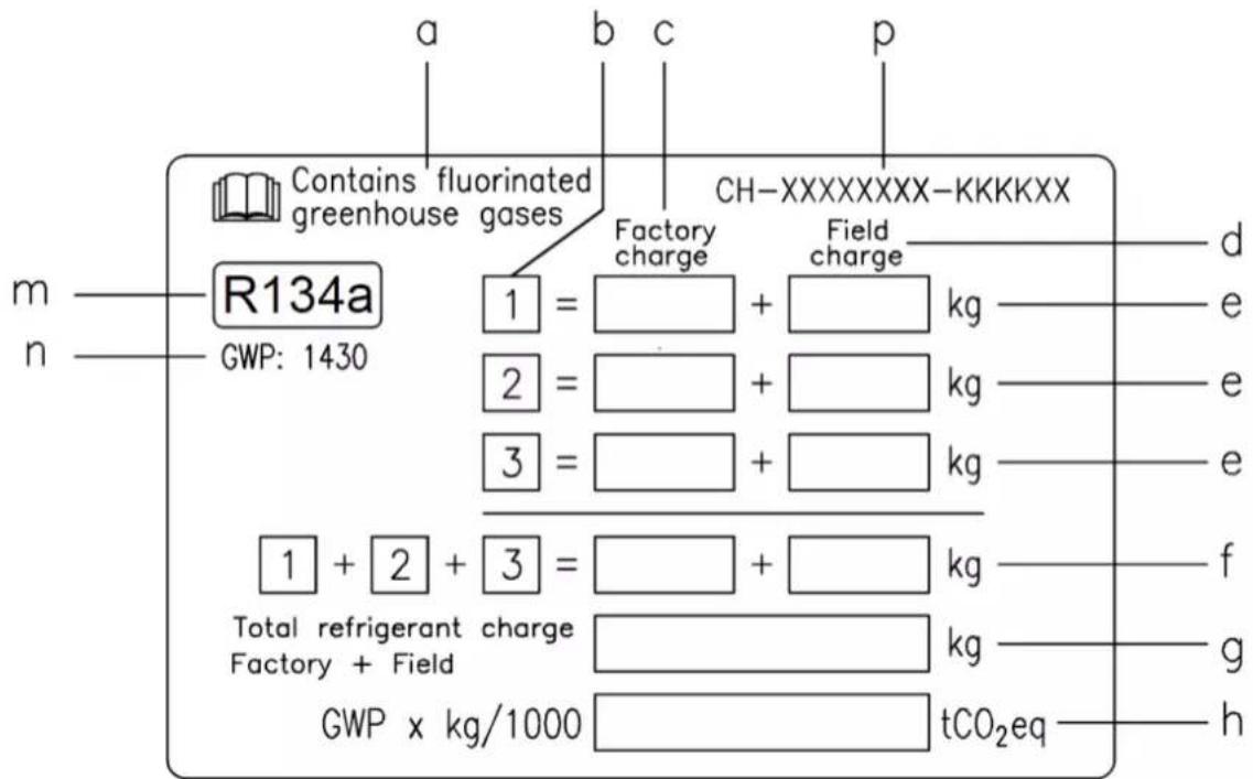
aIpcnyCTBneΦTOpnpoBaHHbIXnapHkoBbIXra3OB
bHomep KOHtypa
c 3aBock03apd
d 3apnHa o6bekTe
e 3aprd XlaadareHt dnn KaKdoro KOHTpya (B COOTBeTCTBnC YHCNOKHTPOB)
f O6u3apxJnaaareHtA
g O6u3apxnaaareHTa (3apnHa 3aBoe+ 3apnHa o6bekTe)
h Bb6pocbl npHkoBx ra3OB nno o6uero 3apraXnaaareHTa, BbipaxeHHbE B ToHHax B nepecheTe Ha CO2
m Tn xJaadaReHa
n GWP = notenuian rnoabhoro noTenneHn (TPI)
p CepnHbH HOMep arperaTa
- 3anonHeHHyO 3TNKETky npNKneNTb BHTpN 3JIeKTPueCKORO LNTa.
Cornacno eBponeckomy nHm MeCTHOMy 3aKoHOnaTeNbCTBy, Ha 3T0 arperat MOrYt pacnpoctpaHrTa cR Tpe6oBaHnO nepoNDueckon npOBepke Ha OTCyTCTBne yTeHeK XnaDareHTa. DononHInTeMbHyIO INΦopMaUHO MOxHO nonuHTb y MeCTHOrO dIepe.
PIMMEAHHE
3NaueHne Bb6pocOB napNKOBbx Ra3OB, 3aBnCJee OToObJero 3apJaXlaIaReHTA BOnCTMe N BbipaxaEMoe B TOHHAX B nepeceTe Ha _2 nONb3yETcB EBpone npOnpeDeneHn HTEpBaNob TexHueckoro 0cbnyKBAHn. Co6IOaTb npImeHMbIe 3aKOHOaTeJIbHbIe HopMbI.
ΦopMylaДЯВыИнсЕнЯБыбрocOBnapнКOBbIXra3OB:
3haueHne IINxnaaareHTa x 06uun 3apd xnaaareHTa (B KInorpammax) / 1000.
HeoXoHMO nCOnb3oBaTb 3aueHne PII, yKa3aHHoe Ha 3tKeTke NapHKOBbix rA3OB. DaHHOe 3aueHne PII NOyueHo a OCHOB MaTePnAIOB 4- ro 3KcpeTHoro OTyeMaexnpabnteJIbCTBeHHo KOMNCCM IO N3MeHEHIO KNIMATA. YKa3aHHoe B pyKOBOdCTBE 3aueHne PII MoKet OKa3aTbCe yCTapeBwIM (HaNPmep, noyueHHbIM Ha OCHObe MaTePnAOB 3- ro 3KcpeTHoro OTyeMaexnpabnteJIbCTBeHHo KOMNCCM IO N3MeHEHIO KNIMATA).
HaCTOaAry N6bnKauHn CoCTaBHe NcKnOHTeBn On n CnpabKn Hne PpeCTaBnEe Tco6oNpeIIOKeHn, 6b3aTeNbHO rnn KOMNaHn Daikin Applied Europe S.p.A. KomnaHn Daikin Applied Europe S.p.A. coCTaBnHa HactoIyU np6bnKaun Ho aocOBaHn MHeIOxCBy Hee CBeHn. KomnaHn He npEOCTaBnEe HnKaknx pRmO BbipaxeHHbx INn NOpa3yMeBaEMbIX rapAHn NOHOTbl, TOOHCTn, HaeXHcNt INN COOTBeTCTBn KOHNpETHOu CEIN B OTHOeHNn COepJAAHn HactoIe N6bnKaun, a TAKKe npDeCTaBnEHhBv Hne ToBapOB u Ycnyr. CneuNfKaun NOnPexKAT I3MeHeHIno 6ez npEBApNTbHO yBeOMLeHn. CM. daHbIe, COo6UHeBn Pn pa3MeueHN 3aKa3a. KomnaHn Daikin Applied Europe S.p.A. noIOXnTEbHO oTKa3bBaetcOn tIO60B ONBeCTBEHNO 3a npMOn INN KOCBeHbY uSep6, B CaOM mIpOKOM TOIKOBAHn 3TOrO cNoBa, Bl3BaHHb NcONJI3OBAHnEM n (IN) ToNKOBAHm E M HactoIe ne NybnKaun. ABTopCKoe npabo Ha BCE codepxHne HactoIe ne NybnKaun npHaadNexknt Daikin Applied Europe S.p.A.
DAIKIN APPLIED EUROPE S.p.A.
Via Piani di Santa Maria, 72 — 00072 Ariccia (Roma) — Italia (Italnia)
Ten.: (+39) 06 93 73 11 — Φακc: (+39) 06 93 74 014
http://www.daikinapplied.eu
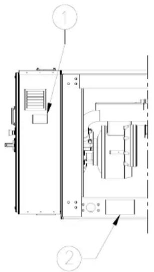
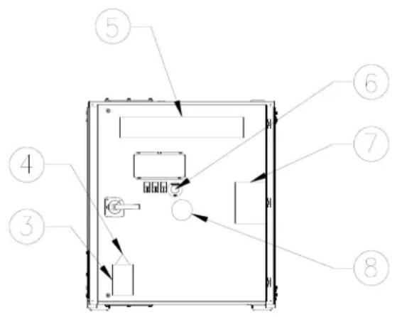
EWWD120J-SS 280J-SS
EWWH090J-SS 200J-SS
EWWS120J-SS 270J-SS
EWLD110J-SS ~ 265J-SS
EWLH80J-SS 190J-SS
EWLS110J-SS 270J-SS