TDP 7501 S - Pump METABO - Free user manual and instructions
Find the device manual for free TDP 7501 S METABO in PDF.
User questions about TDP 7501 S METABO
0 question about this device. Answer the ones you know or ask your own.
Ask a new question about this device
Download the instructions for your Pump in PDF format for free! Find your manual TDP 7501 S - METABO and take your electronic device back in hand. On this page are published all the documents necessary for the use of your device. TDP 7501 S by METABO.
USER MANUAL TDP 7501 S METABO
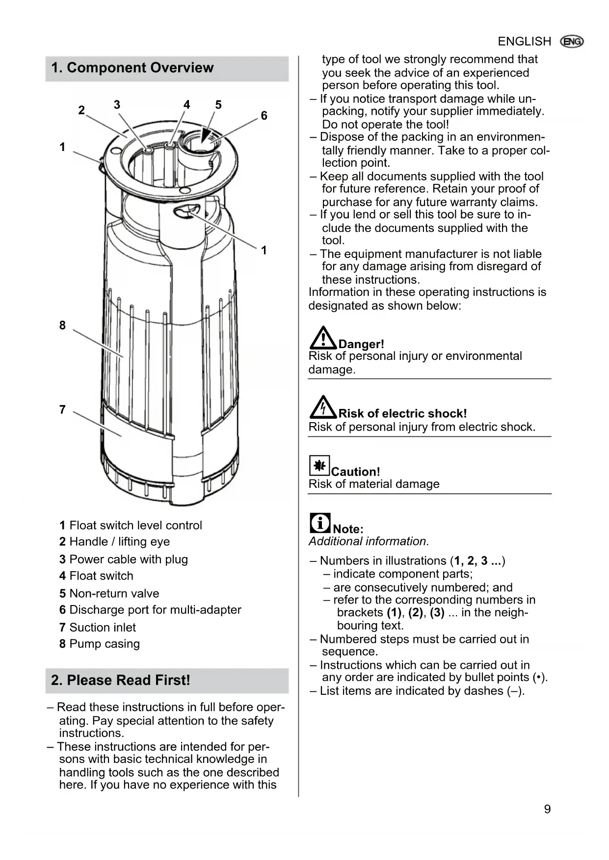
1 Float switch level control
2 Handle / lifting eye
3 Power cable with plug
4 Float switch
5 Non-return valve
6 Discharge port for multi-adapter
7 Suction inlet
8 Pump casing
2. Please Read First!
- Read these instructions in full before operating. Pay special attention to the safety instructions.
- These instructions are intended for persons with basic technical knowledge in handling tools such as the one described here. If you have no experience with this
type of tool we strongly recommend that you seek the advice of an experienced person before operating this tool.
If you notice transport damage while unpacking, notify your supplier immediately. Do not operate the tool!
- Dispose of the packing in an environmentally friendly manner. Take to a proper collection point.
- Keep all documents supplied with the tool for future reference. Retain your proof of purchase for any future warranty claims.
If you lend or sell this tool be sure to include the documents supplied with the tool.
- The equipment manufacturer is not liable for any damage arising from disregard of these instructions.
Information in these operating instructions is designated as shown below:

Danger!
Risk of personal injury or environmental damage.

Risk of electric shock!
Risk of personal injury from electric shock.

Caution!
Risk of material damage

Note:
Additional information.
Numbers in illustrations (1, 2, 3 ...
- indicate component parts;
- are consecutively numbered; and
-
refer to the corresponding numbers in brackets (1), (2), (3) ... in the neighbouring text.
-
Numbered steps must be carried out in sequence.
- Instructions which can be carried out in any order are indicated by bullet points () .
- List items are indicated by dashes (-).
3. Safety
3.1 Specified conditions of use
The pump is intended solely for private use for draining flooded house and garden areas.
Approved pumping media: clean water.
Any other use is considered to be not as specified and not allowed.
Typical application areas
- Drainage of containers, water tanks, swimming pools, soakaways and flooded rooms
- Irrigation of gardens and lawns using underlying water sources, wells or cisterns
Household water supply.
Unspecified use
The pump is not intended for:
- pumping fluids at a temperature >35^
supplying drinking water or pumping liquid food; - pumping salt water;
- pumping explosive, inflammable, aggressive or health-damaging substances or human waste;
- commercial or industrial use; or
- continuous circulation (pond).
The pump should not be used by people (including children and youths) who:
have physical and/or mental impairments;
have impaired senses;
- do not have adequate experience and/or knowledge in handling the pump; or
have not read and understood the operating instructions.
The manufacturer assumes no liability for damage caused by unspecified use.
Unspecified use, modification of the pump or use of parts that have not been tested and approved by the manufacturer can cause unforeseeable damage!
3.2 General safety instructions
- When using this pump observe the following safety instructions to exclude the risk of personal injury or material damage.
- Follow the legal guidelines or accident prevention regulations for use of submersible pumps.
- When the pump is being used in swimming pools and garden ponds and in the protected areas around them, the regulations must be observed in accordance
with DIN VDE 0100-702 and -738.
All local regulations pertaining to the safe operation of submersible pumps must also be followed.
- The pump must be protected by a residual current device (RCD) with a trip current of max 30 mA.
! General danger!
Do not operate the pump if anyone is in contact with the pumping media (e.g. in the swimming pool or garden pond)!
The following residual risks do exist in principle during operation of submersible pumps and cannot be fully eliminated - even through use of safety devices.
Danger from the environment!
Do not use the pump in hazardous locations or near inflammable liquids or gases!
Danger! Risk of electric shock!
Do not touch the plug with wet hands! To unplug always pull on the plug, not the power cable.
Connect only to an earthed outlet that has been properly installed, earthed and tested. Mains voltage and fuse protection must correspond to those stated in the 'Technical Specifications'.
Always lift and transport the pump by the handle, never by the power cable or discharge hose.
Extension cables must have sufficient conductor cross sections. Unroll cable reels fully.
Do not buckle, squeeze, drag or drive over power cable or extension cables; protect from sharp edges, oil and heat.
Position extension cable such that it cannot get into the fluid to be pumped.
Always unplug before servicing the pump.
Risk of electric shock from pump faults!
Before each use check the equipment, especially the power and extension cables, power plug and float switch for possible damage.
Risk of fatal electric shock!
Do not attempt to repair the pump yourself! If repaired improperly there is a danger of fluid penetrating the electrical parts of the pump.
4. Assembly and Installation
4.1 Connecting the discharge line
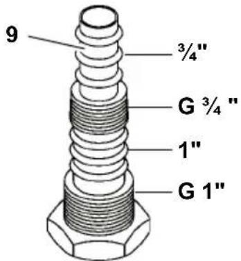
- For selection of the largest discharge line diameter: cut the smaller (9) attachment off the multi-adapter.
i Note:
The best pump capacity is achieved through selection of the largest discharge line diameter.
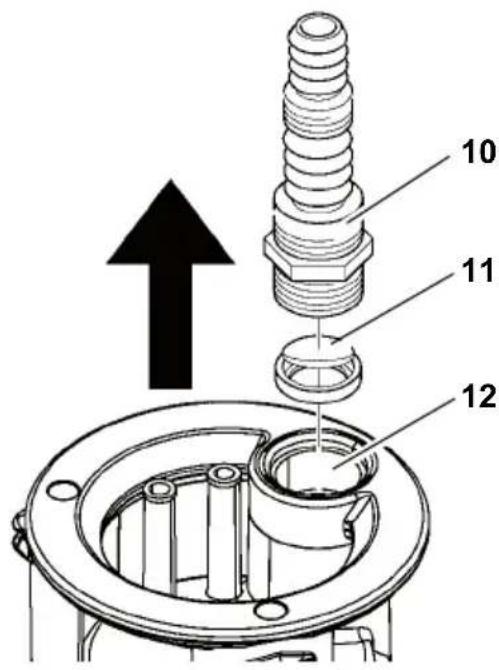
- Place the non-return valve (11) in the discharge port (12). The non-return valve must open in the direction of the arrow (label 'UP' on the non-return valve must point to the multi-adapter).
- Screw the multi-adapter (10) on to the discharge port (12).
- Slide the discharge line over the multi-adapter (10) and secure with a hose clamp.
4.2 Fixing the float switch cable

Note:
Fix the float cable such that the distance between the cable holder and the float switch is at least 100mm
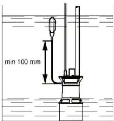
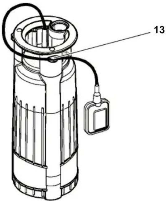
- Clip the float switch cable as illustrated in the cable holder (13). Ensure that the cable is secured in the cable holder in such a way that it cannot slip.
#
Caution!
The float switch cable may be damaged. Never pull on the float switch cable to change its position in the cable holder! Remove the cable from the cable holder and clip it back in the cable holder in the desired position.
4.3 Installation instructions
- Space required: approx. 50 × 50 cm. In order for the float switch to function properly it must be able to move freely.
- Submerge the pump to no more than the maximum immersion depth specified in the technical data.
- Install the pump such that the suction inlets cannot be blocked by foreign objects. If necessary place the pump on a support surface.
- Ensure sufficient upright stability.
#
Risk of electric shock from severed ties!
Do not lift or transport the pump by the cables or the discharge hose! The cables and the discharge hose are not designed to withstand the tensile stress produced by the weight of the pump.
4.4 Installing the pump
- Submerge pump at a slight angle to avoid creating an air cushion on the underside, which would prevent priming. Once the
pump is submerged, it can be placed upright.
- Lower pump to the bottom of the fluid container. Use a strong rope fastened to the lifting eye to lower the pump. The pump can also be operated when suspended by a rope.
- Before operating the pump again ensure that the pump line has been completely emptied. When doing so vent the pump if necessary.
5. Operation
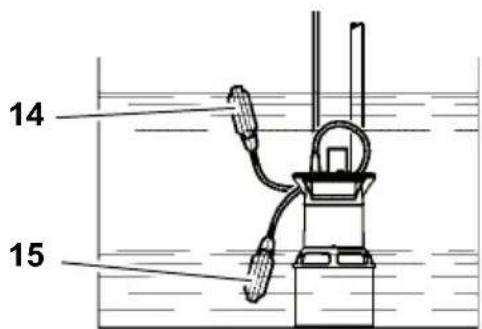
5.1 Switching ON and OFF
After you have connected the pump to the mains it will be switched on (14) and off (15) automatically by the float switch. The point in time at which switching occurs depends on the water level.
Adjusting the ON and OFF times for the pump
The position of the float switch cable in the cable holder can be changed. The time interval between pump switch-on and switch-off is thereby adjusted:
- 'Short' float switch cable: ON and OFF positions are close together.
- 'Long' float switch cable: ON and OFF positions are far apart.
#
Caution!
The pump may run dry and thereby be damaged.
The float switch must always be able to move up and down to allow the pump to be switched on and off.
#
Danger from faulty pump!
Take appropriate measures to ensure that pump faults do not cause consequential
damage through flooding of rooms. This must be ensured, for example, through installation of an alarm system or a reserve pump.

Do not let the pump run against a closed pump line.
6. Pump Care

Unplug before maintaining or cleaning.
Repair and maintenance work other than described in this section should only be carried out by qualified specialists.
6.1 Routine care
For the pump to function perfectly at all times routine care is required. This also applies if the pump is not switched on for extended periods of time (e.g. during operation in soakways).
Cleaning the pump
- Rinse pump with clean water. Remove persistent marks, e.g. algae deposits, with brush and dishwashing liquid.
- To rinse the inside of the pump: dip pump into a container of clean water and switch on briefly.
6.2 Pump storage

Frost damages the pump and accessories as both always contain water!
- If there is a danger of frost disassemble pump and accessories and store in frost-free conditions.
7. Troubleshooting

Prior to all servicing:
Unplug.
7.1 Troubleshooting guide
Pump does not run:
No mains voltage.
-
Check cables, plug, outlet and mains fuse.
-
Mains voltage too low.
-
Use an extension cable with sufficient conductor diameter.
-
Motor overheated; motor protection relay tripped.
-
Eliminate the cause of overheating (pump blocked by foreign objects?).
-
After cooling the pump will switch ON again.
-
Float switch does not switch pump ON when water level rises.
-
Make sure the float switch can move unrestrictedly.
If, despite sufficient mobility of the float switch, the pump does not switch ON: send the pump to the service centre in your country.
Motor hums, but does not start:
- Pump blocked by foreign objects.
Clean impeller.
Pump runs, but does not pump properly:
Delivery head too high.
- Observe max delivery head (see 'Technical Specifications').
- Discharge hose kinked.
- Straighten discharge hose.
- Discharge hose leaky.
- Seal discharge hose; tighten screw fittings.
- Non-return valve incorrectly installed.
Pump runs very noisily:
-
Pump is sucking air.
-
Ensure there is a sufficient water supply.
- Foreign objects are present (clean pump).
- Manual mode has been set (shallow water suctioning).
- Hold pump at an angle when submerging.
Pump runs continuously:
- Float switch does not reach cut-out position.
- Make sure the float switch can move unrestrictedly.
8. Repairs

Danger!
Repair of power tools must be carried out by qualified electricians only!
Power tools in need of repair can be sent to the service centre in your country. Refer to spare parts list for address.
Please attach a description of the fault to the power tool.
9. Disposal
Power tools do not belong in the household rubbish. According to European
Directive 2002/96/EC on waste electrical and electronic equipment, electrical waste must
be collected separately and taken
to an environmentally friendly recycling facility.
Contact your local council for information on disposal of the used tool.
All packaging materials are recyclable.
For lav netspaending.
Andra pumpens start/stopp
Pump tootab vaga valjult:
6.1 Regulara kopsana
Motors duc, bet nesak darbodies:
-
Rotoru nosprostojis sveskermenis.
-
I z t irit rotoru.
Sūknis darbojas, bet neveic sūknešanu pareizi: