SHD 100 S - Boiler STIEBEL ELTRON - Free user manual and instructions
Find the device manual for free SHD 100 S STIEBEL ELTRON in PDF.
| Product type | Electric storage and instantaneous water heater |
| Brand | Stiebel Eltron |
| Model | SHD 100 S |
| Nominal capacity | 100 L |
| Dimensions (H x W x D) | 1050 x 510 x 510 mm |
| Weight (empty) | 40.1 kg |
| Weight (full) | 140.1 kg |
| Electrical supply | 400 V three-phase, 3/PE ~400V, 50 Hz |
| Power | 3.5 kW (normal) / 21 kW (fast) |
| Temperature range | 35 °C to 85 °C |
| Maximum allowable pressure | 0.6 MPa |
| Protection rating | IP25 |
| Tank type | Enameled steel with protective anode |
| Operating modes | Single power, dual power, instantaneous |
| Special functions | Fast heating, frost protection, anode wear indicator |
| Energy efficiency class | C |
| Noise level | 15 dB(A) |
| Off-peak compatible | Yes |
| Safety requirements | Mandatory safety valve, residual-current circuit breaker |
| Maintenance | Descaling, draining, anode replacement |
| Warranty | According to subsidiary conditions |
Frequently Asked Questions - SHD 100 S STIEBEL ELTRON
User questions about SHD 100 S STIEBEL ELTRON
0 question about this device. Answer the ones you know or ask your own.
Ask a new question about this device
Download the instructions for your Boiler in PDF format for free! Find your manual SHD 100 S - STIEBEL ELTRON and take your electronic device back in hand. On this page are published all the documents necessary for the use of your device. SHD 100 S by STIEBEL ELTRON.
USER MANUAL SHD 100 S STIEBEL ELTRON
- General information 17
1.1 Safety instructions 17
1.2 Other symbols in this documentation 17
1.3 Units of measurement 17 - Safety 17
2.1 Intended use 17
2.2 General safety instructions 18
2.3 Test symbols 18
3.Appliance description 18 - Settings 19
- Cleaning, care and maintenance 19
- Troubleshooting 19
INSTALLATION
- Safety 20
7.1 General safety instructions 20
7.2 Instructions, standards and regulations 20 - Appliance description 20
8.1 Standard delivery 20
8.2 Accessories 20
9.Preparations 20
9.1 Installation site 20
9.2 Fitting the wall mounting bracket 20
9.3 Preparing the power cable 20 - Installation 21
10.1 Water connection 21
10.2 Appliance installation 21
10.3 Power supply 21 - Commissioning 22
11.1 Initial start-up 22
11.2 Recommissioning 22 - Settings 22
- Shutdown 23
- Troubleshooting 23
- Maintenance 23
15.1 Checking the safety valve 23
15.2 Draining the appliance 23
15.3 Replacing the protective anode 24
15.4 Descaling 24
15.5 Anti-corrosion protection 24 - Specification 25
16.1 Dimensions and connections 25
16.2 Wiring diagrams and terminals 26
16.3 Output tables 27
16.4 Fault conditions 27
16.5 Details on energy consumption 27
16.6 Data table 27
GUARANTEE
ENVIRONMENT AND RECYCLING
SPECIAL INFORMATION
- The appliance may be used by children aged 8 and older and persons with reduced physical, sensory or mental capabilities or a lack of experience and know-how, provided that they are supervised or they have been instructed on how to use the appliance safely and have understood the resulting risks. Children must never play with the appliance. Children must never clean the appliance or perform user maintenance unless they are supervised.
- The connection to the power supply is only permissible as a permanent connection in conjunction with the removable cable grommet. Ensure the appliance can be separated from the power supply by an isolator that disconnects all poles with at least 3mm contact separation.
Fix the appliance in position as described in chapter "Installation / Preparations". - Observe the maximum permissible pressure (see chapter "Installation / Specification / Data table").
- Drain the appliance as described in chapter "Installation / Maintenance / Draining the appliance".
- The appliance is pressurised. During the heat-up process, expansion water will drip from the safety valve.
- Regularly activate the safety valve to prevent it from becoming blocked, e.g. by limescale deposits.
- Install a type-tested safety valve in the cold water supply line. Please note that, depending on the static pressure, you may also need a pressure reducing valve.
- Size the drain pipe so that water can drain off unimpeded when the safety valve is fully opened.
- Fit the discharge pipe of the safety valve with a constant downward slope and in a room free from the risk of frost.
- The safety valve discharge aperture must remain open to atmosphere.
OPERATION
1. General information
The chapters "Special Information" and "Operation" are intended for both the user and qualified contractors.
The chapter "Installation" is intended for qualified contractors.

Note
Read these instructions carefully before using the appliance and retain them for future reference.
Pass on the instructions to a new user if required.
1.1 Safety instructions
1.1.1 Structure of safety instructions

KEYWORD Type of risk
Here, possible consequences are listed that may result from failure to observe the safety instructions.
Steps to prevent the risk are listed.
1.1.2 Symbols, type of risk
Symbol Type of risk

Injury

Electrocution

Burns
(burns, scalding)
1.1.3 Keywords
KEYWORD Meaning
DANGER Failure to observe this information will result in serious injury or death.
WARNING Failure to observe this information may result in serious injury or death.
CAUTION Failure to observe this information may result in non-serious or minor injury.
1.2 Other symbols in this documentation

Note
General information is identified by the adjacent symbol.
Read these texts carefully.
Symbol Meaning

Material losses
(appliance damage, consequential losses and environmental pollution)
Appliance disposal

This symbol indicates that you have to do something. The action you need to take is described step by step.
1.3 Units of measurement

Note
All measurements are given in mm unless stated otherwise.
2. Safety
2.1 Intended use
The appliance is intended for heating domestic hot water and can supply one or more draw-off points.
This appliance is intended for domestic use. It can be used safely by untrained persons. The appliance can also be used in a non-domestic environment, e.g. in a small business, as long as it is used in the same way.
Any other use beyond that described shall be deemed inappropriate. Using the appliance for heating fluids other than water or for water supplemented with chemicals, such as brine, is also deemed inappropriate.
Observation of these instructions and of instructions for any accessories used is also part of the correct use of this appliance.
2.2 General safety instructions

WARNING Burns
During operation, the tap/valve and safety assembly can reach temperatures in excess of 60^ .
There is a risk of scalding at outlet temperatures in excess of 43^

WARNING Injury
The appliance may be used by children aged 8 and older and persons with reduced physical, sensory or mental capabilities or a lack of experience and know-how, provided that they are supervised or they have been instructed on how to use the appliance safely and have understood the resulting risks. Children must never play with the appliance. Children must never clean the appliance or perform user maintenance unless they are supervised.

Material losses
The user should protect the water lines and the safety assembly against frost.

Note
The appliance is pressurised. During the heat-up process, expansion water will drip from the safety valve.
If water continues to drip when heating is completed, please inform your qualified contractor.
2.3 Test symbols
See type plate on the appliance.
3. Appliance description
The appliance electrically heats up domestic hot water with the standard heating output or with rapid heating. You can adjust the temperature using the temperature selector. Subject to the power supply, the water is automatically heated to the required temperature.
You can use the appliance in single circuit, dual circuit or instantaneous water cylinder mode.
The internal steel cylinder is coated in "anticor" enamel and is equipped with a protective anode. The anode protects the internal cylinder from corrosion.
Frost protection
In single circuit and instantaneous water cylinder mode, the appliance is also protected against frost on the temperature setting "cold", as long as the power supply is guaranteed. The appliance switches on in good time and heats the water. The appliance does not protect the water supply lines and the safety assembly against frost. In dual-circuit operation, frost protection is only available during off-peak tariff periods.
Instantaneous water cylinder mode
In this operating mode, the appliance works with normal heating output when drawing off small amounts of water.
At high temperature settings and after large amounts of water have been drawn off, the appliance automatically switches over to booster heater (see chapter "Specification / Data table").
After the full amount of heated water in the cylinder has been drawn off, the appliance works in instantaneous mode with a booster heater. The available amounts of water that can be drawn off are reduced accordingly (see chapter "Specification / Output tables").
Following a longer power failure, the zero volt relay prevents the booster heater from being switched on straight away. Once the voltage returns, the appliance initially works with normal heating output until the temperature controller reacts for the first time. Subsequently, rapid heating is automatically ready for operation again.
Dual circuit operation
During off-peak tariff periods (power supply companies' cheap rate periods), the appliance automatically heats up the water content with standard heating output at all temperature settings. In addition, you can start the booster heater during peak tariff periods.
Single circuit operation
In this operating mode, the appliance heats up the water automatically subject to the connected heating output and temperature setting.
4. Settings
The temperature can be freely adjusted.
In single circuit and dual-circuit operation, the temperature setting can be limited by the qualified contractor (see chapter "Installation / Settings").
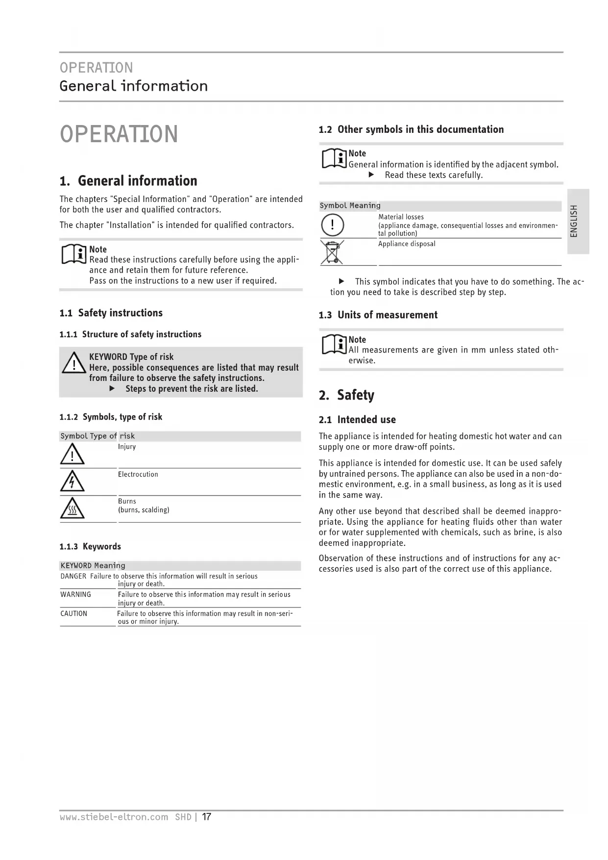
1 ON/OFF indicator for rapid heating
2 Rapid heating pushbutton (in dual-circuit operation)
3 Temperature selector
Cold
E Recommended energy saving position, low scaling, 60^
85^ Maximum temperature setting
4 "SERVICE ANODE" indicator
Depending on the system, the actual temperatures may vary from the set value.
ON/OFF indicator
The ON/OFF indicator light illuminates while the water is heated by the booster heater.
Rapid heating pushbutton in dual-circuit operation
You can switch on rapid heating with the pushbutton. A remote control can also be installed for this purpose. Rapid heating stops and will not restart when the selected temperature has been reached.
"SERVICE ANODE" indicator

Material losses
- Notify your qualified contractor if the SERVICE ANODE indicator illuminates.
Instantaneous water cylinder operation following a power failure
Following a longer power failure, you can switch the booster heater on manually straight away by first turing the temperature selector to the "cold" position and then up to 85^
5. Cleaning, care and maintenance
Have the electrical safety of the appliance and the function of the safety valve regularly checked by a qualified contractor.
The protective anode must be replaced by a qualified contractor as soon as the SERVICE ANODE indicator illuminates (see chapter "Maintenance / Replacing the protective anode").
Never use abrasive or corrosive cleaning agents. A damp cloth is sufficient for cleaning the appliance.
Scaling
Almost every type of water will deposit limescale at high temperatures. This settles inside the appliance and affects both the performance and service life. The heating elements must therefore be descaled from time to time. A qualified contractor who knows the local water quality will tell you when the next service is due.
- Check the taps regularly. Limescale deposits at the tap outlets can be removed using commercially available descaling agents.
Regularly activate the safety valve to prevent it from becoming blocked, e.g. by limescale deposits.
6. Troubleshooting
| Problem Cause Remedy | ||
| The water does not heat up. | There is no power. | Check the fuses / MCBs in your fuse box/distribu-tion panel. |
| The flow rate is low. | The aerator in the tap or the shower head is scaled up or contami-nated. | Clean and/or descale the aerator or shower head. |
| SERVICE ANODE indicator illuminates. | Replace the protective anode. | Notify your qualified contractor. |
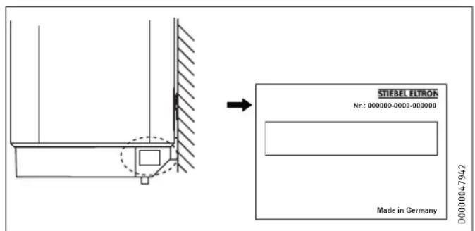
If you cannot remedy the fault, notify your contractor. To facilitate and speed up your enquiry, please provide the serial number from the type plate (000000-0000-000000):
INSTALLATION
7. Safety
Only a qualified contractor should carry out installation, commissioning, maintenance and repair of the appliance.
7.1 General safety instructions
We guarantee trouble-free function and operational reliability only if original accessories and spare parts intended for the appliance are used.
7.2 Instructions, standards and regulations

Note
Observe all applicable national and regional regulations and instructions.
8. Appliance description
8.1 Standard delivery
The following are delivered with the appliance:
- Wall mounting bracket
- 5 mm spacer (2 pce for above, 2 pce for below)
- Caps (2 pce)
- Installation template
8.2 Accessories
Required accessories
Various safety assemblies are available that need to be selected subject to the static pressure. These type-tested safety assemblies protect the appliance against impermissible excess pressure.
Further accessories
The load shedding relay activates the priority control during operation of the appliance when you are simultaneously operating another appliance, such as an electric storage heater (for connection, see chapter "Specification / Wiring diagrams and connections").
9. Preparations
9.1 Installation site
The appliance is designed for installation on a solid wall. Ensure the wall offers adequate load bearing capacity.
Install the appliance vertically in a room free from the risk of frost and near the draw-off point.
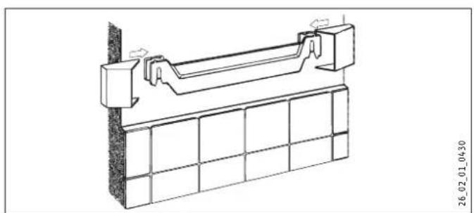
9.2 Fitting the wall mounting bracket
- You can use the installation template to transfer the dimensions to the wall.
- Drill the holes and secure the wall mounting bracket with screws and rawl plugs. Select fixing materials in accordance with the wall construction/condition.
You can compensate for unevenness in the wall with the spacers provided.
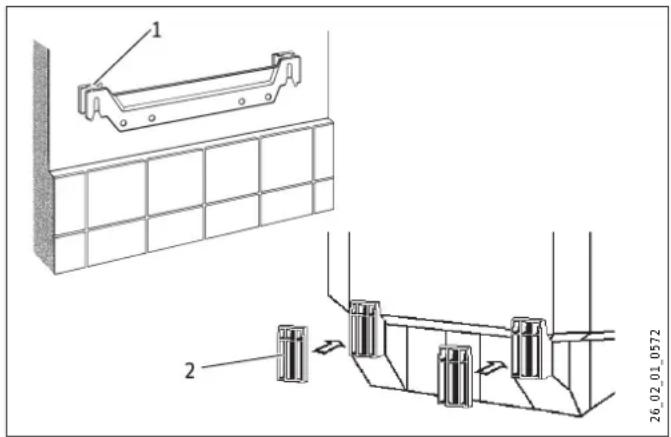
1 Upper spacer
2 Lower spacer
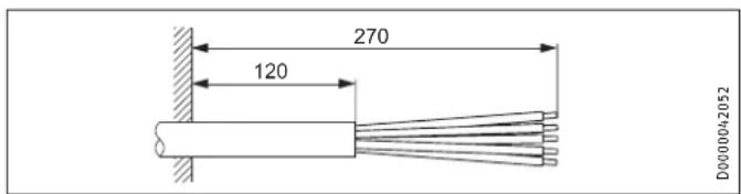
9.3 Preparing the power cable
10. Installation
10.1 Water connection

Material losses
Carry out all water connection and installation work in accordance with regulations.
- Connect the hydraulic connections with flat gaskets.
- Operate the appliance only with pressure-tested taps.
10.1.1 Permissible materials
Cold water line
Galvanised steel, stainless steel, copper and plastic are approved materials.
A safety valve is required.
DHW line

Material losses
The appliance is not suitable for the use of plastic piping for the DHW line.
Stainless steel and copper are approved materials.
The maximum permissible pressure must not be exceeded (see chapter "Specification / Data table").
10.1.2 Fitting the safety valve
Install a type-tested safety valve in the cold water supply line. Please note that, depending on the static pressure, you may also need a pressure reducing valve.
- Size the drain pipe so that water can drain off unimpeded when the safety valve is fully opened.
Fit the discharge pipe of the safety valve with a constant downward slope and in a room free from the risk of frost.
The safety valve discharge aperture must remain open to atmosphere.
10.2 Appliance installation
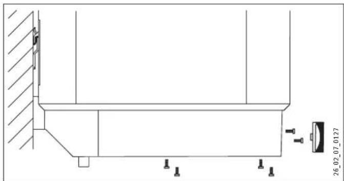
Hang the appliance on the wall mounting bracket.
Fit the caps.
10.3 Power supply

WARNING Electrocution
Carry out all electrical connection and installation work in accordance with relevant regulations.
Before any work on the appliance, disconnect all poles from the power supply.

WARNING Electrocution
The connection to the power supply is only permissible as a permanent connection in conjunction with the removable cable grommet. Ensure the appliance can be separated from the power supply by an isolator that disconnects all poles with at least 3mm contact separation.

WARNING Electrocution
Ensure that the appliance is earthed.

Material losses
Install a residual current device (RCD).

Material losses
Observe the type plate. The specified voltage must match the mains voltage.
Pull off the temperature selector.
Undo the screws.
Remove the lower cap.
Pull the cable grommet out downwards while pressing on the locking hooks.
- Push the cable grommet over the power cable and snap the cable grommet back in place.
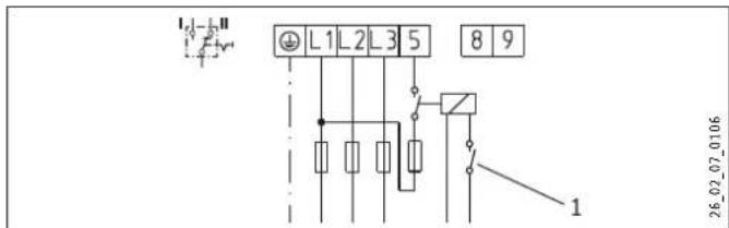
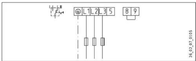
Connect the required load in accordance with the wiring diagrams (see chapter "Specification / Wiring diagrams and terminals").
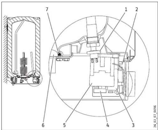
1 Pressure switch for protective anode
2 Operating mode switch
3 Temperature controller
4 Electronic assembly.
5 Contactor
6 Flange plate
7 Seal ring
Select the operating mode using the switch:
Position I = Instantaneous water cylinder mode
Position II = Dual-circuit/single circuit operation
(see chapter "Specification / Wiring diagrams and connections").
Fit the lower cap.
Insert the screws.
Push on the temperature selector.
- Tick the selected connected load and voltage on the type plate with a ballpoint pen.
Connect the safety assembly to the appliance by screwing pipes onto the appliance.
11. Commissioning
11.1 Initial start-up
- Open a draw-off point until the appliance has filled up and the pipework is free of air.
Adjust the flow rate. For this, observe the maximum permissible flow rate with a fully opened tap (see chapter "Specification / Data table").
If necessary reduce the flow rate at the butterfly valve of the safety valve.
Turn the temperature selector to maximum.
Switch the mains power ON.
Check the function of the appliance. Ensure that the temperature controller switches off.
Check that the safety valve is working correctly.
11.1.1 Appliance handover
Explain the function of the appliance and safety assembly to users and familiarise them with their operation.
Make the user aware of potential dangers, especially the risk of scalding.
Hand over these instructions.
11.2 Recommissioning
See chapter "Commissioning / Initial start-up".
12. Settings
Limiting the temperature selection
Factory setting: 85^

Note
You can install a central thermostatic valve at the DHW outlet if the temperature selection limit is set to 85^ . This enables the reduction of the outlet temperature.
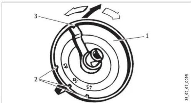
1 Temperature selector
2 The temperature selection limit can be adjusted to 45^ 55^ or 65^
3 85°C
Set the temperature selection limit.
13. Shutdown
-
Disconnect the appliance from the mains at the MCB/fuse in the fuse box.
-
Drain the appliance. See chapter "Maintenance / Draining the appliance".
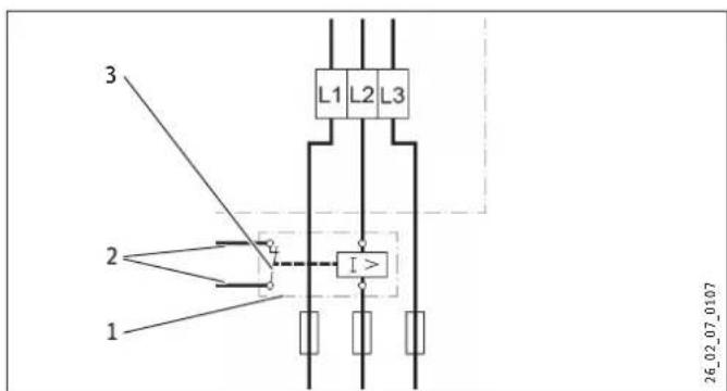
14. Troubleshooting

At temperatures below -15^ the high limit safety cut-out may respond. The appliance may be subjected to these temperatures during storage or transport.
| Fault Cause Remedy | ||
| The water does not heat up. | The high limit safety cut-out has responded because the controller is faulty. | Remedy the cause of the fault. Replace the temperature controller. |
| The high limit safety cut-out has responded because the temperature has fallen below -15 °C. | Press the reset button (see diagram). | |
| The flanged immersion | Rapid heating does not switch on. | Test the pushbutton and lever. |
| heater is faulty. | Replace the flanged immersion heater. | |
| The selected outlet temperature is not reached during instantaneous water cylinder mode when the draw-off valve is fully opened. | More water flows through the appliance than the heating element can heat up. | Reduce the amount of water at the DHW valve. |
| The safety valve drips when heating is switched off. | The valve seat is contaminated. | Clean the valve seat. |
Reset button, high limit safety cut-out
1 High limit safety cut-out
2 Reset button
15. Maintenance

WARNING Electrocution Carry out all electrical connection and installation work in accordance with relevant regulations. Before any work on the appliance, disconnect all poles of the appliance from the power supply.
For some maintenance work, the lower cap must be removed. If you need to drain the appliance, observe chapter "Draining the appliance".
Note the insertion depths of the temperature controller (see chapter "Specification / Dimensions and connections").
15.1 Checking the safety valve
Check the safety valve regularly.
15.2 Draining the appliance

WARNING Burns Hot water may escape during the draining process.
If the appliance needs to be drained for maintenance or to protect the whole installation when there is a risk of frost, proceed as follows:
- Close the shut-off valve in the cold water inlet line.
Open the hot water taps on all draw-off points.
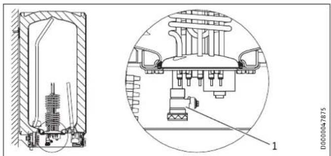
1 Drain valve with hose connection G 3/4
Screw a hose onto the drain valve.
Open the drain valve.
15.3 Replacing the protective anode
If the SERVICE ANODE indicator illuminates, check the signal anode and replace if necessary. Spanner size for the anode
- SHD 30 S: SW 13
- SHD 100 S: SW 27
When replacing the anode, take great care to fit the pressure switch on tightly (tighten by hand, torque value 100^+50 Ncm).
Observe the maximum permissible transition resistance 1.0 between the anode and the cylinder
15.4 Dscaling
Only descale the flange after disassembly.
- Never treat the cylinder surface or the protective anode with descending agents.
15.5 Anti-corrosion protection
When carrying out service work, ensure that the anti-corrosion protection on the insulating plate is not damaged or removed. Reinsert the anti-corrosion protection correctly after replacement.
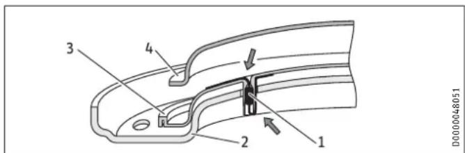
1 Anti-corrosion protection (390 Ω)
2 Pressure plate
3 Insulating plate
4 Flanged immersion heater
16. Specification
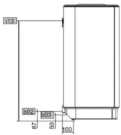
16.1 Dimensions and connections
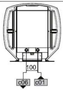
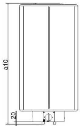
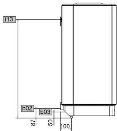
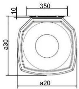
D000024812
| SHD 30 S SHD 100 S | |||||
| a10 | Appliance | Height | mm | 770 | 1050 |
| a20 | Appliance | Width | mm | 410 | 510 |
| a30 | Appliance | Depth | mm | 420 | 510 |
| b02 | Entry electrical cables I | ||||
| b03 | Entry electrical cables II | ||||
| c01 | Cold water inlet | Male thread | G 1/2 A | G 1/2 A | |
| c06 | DHW outlet | Male thread | G 1/2 A | G 1/2 A | |
| i13 | Wall mounting bracket | Height | mm | 700 | 900 |
| Max. Ø fixing screw | mm | 12 | 12 | ||
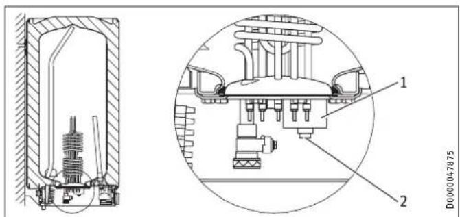
Immersion depth of thermostat sensor
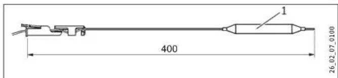
1 Thermostat sensor
16.2 Wiring diagrams and terminals
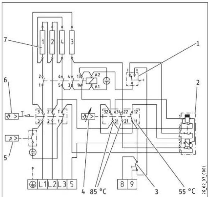
1 Operating mode switch
2 Electronic assembly with zero volt and switching relay
3 Rapid heating pushbutton
4 Temperature controller
5 Pressure switch for protective anode
6 High limit safety cut-out
7 Heating element
Heating element
| 1 2 4 3 | ||||
| kW | 7.0 | 7.0 | 3.5 | 3.5 |
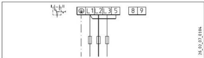
Instantaneous water cylinder mode
3.5/21 kW, 3/PE ~ 400 V
Dual circuit operation
Single-meter counting with power-OFF contact: 3.5 / 21kW 3/PE 400V
1 Power-OFF contact
Dual-meter measurement with power-OFF contact: 3.5/21 kW, 3/ PE 400 V
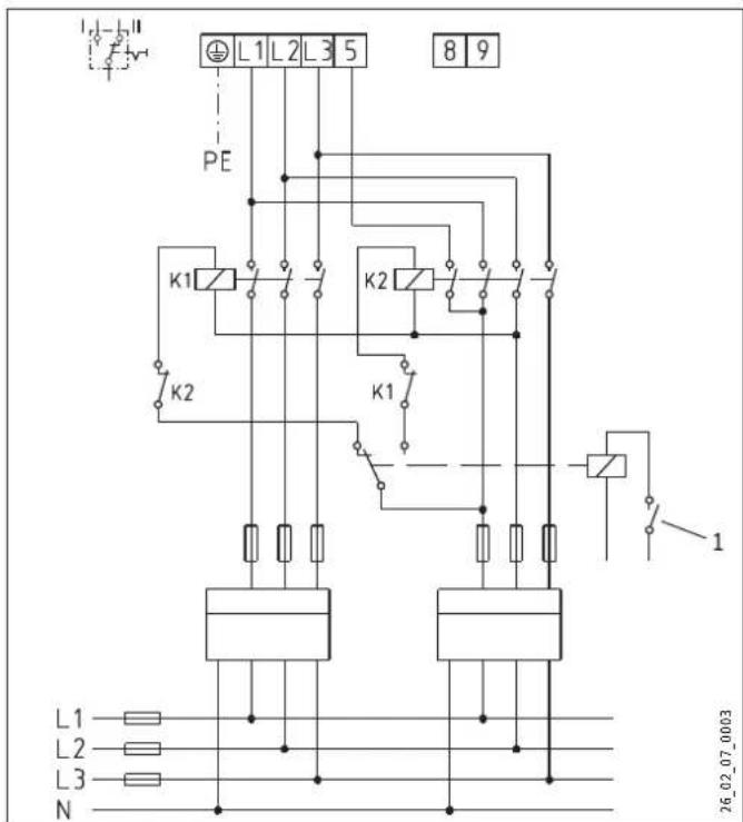
1 Power-OFF contact
Single circuit operation
21 kW, 3/PE ~ 400 V
Load shedding relay LR 1-A
1 Load shedding relay
2 Control cable to the contactor of the second appliance
3 Control contact, opens when switching on the SHD S
16.3 Output tables
The heat-up time depends on the cylinder capacity, cold water inlet temperature and heating output. For the heat-up time with the booster heater (21 kW) and a cold water supply of 10^ , see the following table.
| Heat-up time (cylinder operation) | |||
| Temperature setting range | °C | 65 | 85 |
| SHD 30 S min 6 8 | |||
| SHD 100 S min 18 25 | |||
In instantaneous DHW cylinder operation, the following amounts of hot water can be drawn off.
| DHW output (instantaneous operation) | |||
| DHW temperature | °C | 38 | 55 |
| Cold water supply 6 °C | l/min | 9.4 | 6.1 |
| old water supply 10 °C | l/min | 10.7 | 6.7 |
| old water supply 14 °C | l/min | 12.7 | 7.3 |
16.4 Fault conditions
In the event of a fault, temperatures of up to 130^ at 0.6 MPa can occur.
16.5 Details on energy consumption
Product datasheet: Conventional water heaters to regulation (EU) no. 814/2013
| SHD 30 S | SHD 100 S | |
| 073059 | 073060 | |
| Manufacturer | STIEBEL ELTRON | STIEBEL ELTRON |
| Load profile | S | L |
| Energy efficiency class | B | C |
| Energy conversion efficiency | % | 36 |
| Daily power consumption | kWh | 2.437 |
| Annual power consumption | kWh | 518 |
| Default temperature setting | °C | 60 |
| Sound power level | dB(A) | 15 |
| Off-peak periods possible | Yes | Yes |
16.6 Data table
| SHD 30 S | SHD 100 S | ||
| 073059 | 073060 | ||
| Hydraulic data | |||
| Nominal capacity | I | 30 | 100 |
| Mixed water volume 40 °C (15 °C/65 °C) | I | 59 | 195 |
| Electrical data | |||
| Connected load ~ 400 V | kW | 3.5/21 | 3.5/21 |
| Phases | 3/PE | 3/PE | |
| Rated voltage | V | 400 | 400 |
| Frequency | Hz | 50 | 50 |
| Single circuit operating mode X | X | ||
| Dual circuit operating mode | X | X | |
| Application limits | |||
| Temperature setting range | °C | 35-85 | 35-85 |
| Max. permissible pressure | MPa | 0.6 | 0.6 |
| Test pressure | MPa | 0.78 | 0.78 |
| Max. permissible temperature | °C | 110 | 110 |
| Max. flow rate | l/min | 18 | 18 |
| Min./max. conductivity, drinking water | μS/cm | 100-1500 | 100-1500 |
| Energy data | |||
| Standby energy consumption/24 h at 65 °C | kWh | 0.46 | 0.86 |
| Energy efficiency class | B | C | |
| Versions | |||
| IP rating | IP25 | IP25 | |
| Sealed unvented type | X | X | |
| Colour | White | White | |
| Dimensions | |||
| Height | mm | 770 | 1050 |
| Width | mm | 410 | 510 |
| Depth | mm | 420 | 510 |
| Weight | |||
| Weight, full | kg | 54.3 | 140.1 |
| Weight, empty | kg | 24.3 | 40.1 |
Guarantee
The guarantee conditions of our German companies do not apply to appliances acquired outside of Germany. In countries where our subsidiaries sell our products a guarantee can only be issued by those subsidiaries. Such guarantee is only granted if the subsidiary has issued its own terms of guarantee. No other guarantee will be granted.
We shall not provide any guarantee for appliances acquired in countries where we have no subsidiary to sell our products. This will not affect warranties issued by any importers.
Environment and recycling
We would ask you to help protect the environment. After use, dispose of the various materials in accordance with national regulations.
REMARQUESPARTICULIERES
UTILISATION
Ecn He yka3aHO nHoe, BCE pa3MepbI npNBedeHbIB MnnnMeTpax.
2. TexHnka 6e3OnacHoCTn
2.1 McnoIb3OBAHne no Ha3HaueHmIO
Pnp6op npedHa3NaeH nla HarpBa BOOpPOBOHOBbIMoKet 06cnykBaT bOHy nI IN HeckOJbKO TOeEe OT6opa.
Pnp6op npedHa3HaeH dna 6bI0BOro nCnOJIb3OBaHn.ДЯ ero 6e3onacHOrO o6cnyKINBaHn NOJb3OBaTeH He Tpe6yETc npoxoNTb NHTCPyKTax Bo3MOxHO nCnOJIb3OBaHne np6oopa He TOnbKO B 6bity, Ho n, HApnPmep, Ha npEiPnTnxMaoro 6u3HeCa npu ycIOBn CO6JIIODeHn Tex Xe yCIOBn EKcnIy-ataun.
IIO6oe INHOe IIN He yka3aHHoe B HactoJcem pyKOBODCTBE NCNoB3OBAHHe DaHHoro YcTPOJCTBa CHTAeTcN CNOb3OBAHnEM He No Ha3HaueHIO. NcNoB3OBAHnEM He No Ha3HaueHIO CHTAeTc TaKKe NcNoB3OBAHne np6Op dJa HarpeBa IIO6bIX dpyrNX JxuKocTei KpOME BObl, a TAKKe HArpeB BObl c DoabNeHNem XIMnKaJIH, HanPmEp, paccOna.
NcnoB3ObaHne no Ha3NaueHnIO npda3yMeBaet co6IIOJeHne Tpe6oBaHn HacToaIero pyKOBoIDCTBa, a TaKKe pyKOBOdCTB K NcNoB3yEmbIM npHaadJnxHOCTM.
2.2 06uye kazanno TeHNKe 6e3onacHOCTn

PPEyIPEKDEHNE oxor
Bo Bpempa60tbpn60pa apMaTpyu npedeoxpanHTeBHa rpynna moryr HargpeBaTbcra do TemnepaTpybCBblwe 60^
Pn TemnepaType BObI Ha BixOe Bblue 43 ^ C cyuecCTByET ONaCHOCtB O6BapnBaHn.

PPEyIpyEKDEHNE TpaBma
DeTAM CTAPwe 8 let, a TAKKHe IINUaM C orpaHnueHHbIMn OHN3NUeCKHMn, CEHCOPHBIMn UYMCTBHeHHbIMn CNOCO6HOCTAMn, He IMMeIOUIM ONbTa N He BNaJeIOUIm INHOpMaunne O np6ope, pa3peSeHo NCNoJIb3OBaTB np6Op TOlbKO NOI pNcMOTpOM dpyrnx IuN IIN NocLe COOTBeTCTByUoJero IHCTpykTaJa O npaBnJax 6E3ONACHO rONb3OBaHnN I NOTEHcuaNBHOOnacCHOCTN BcIyueh EecO6JIouDeHnN 3TNx nPabNl. He DONYCKATb WAnIOCTeN DetEn C np6OpOM. DeTm MOrYT BbINONHtB YNCKy np6opa N Te BNDbI TexHnueckoRo 06CInjKBaHnN, KOToPBie 06bHuO pOn3BOaTcR NOB3OBaTelem, TOlbKO NOI npcMOTpOM B3POCbIX.

MaTePnAJIbHbIy uIeep6
BoonpoBOn n npedoxpaHnteHbHa rpynna doJxHb6bTb 3aunuHbI Nb3OBaTeJeM OT 3aMeP3aHn.

Yka3aHne
Ipn6op haoonTcnoD abneneM.BoBpemHaRpeBa BCNECTBne TnIOBOrO paunpeHna BOna KaNaeN3 PnpdoxpanTehBOrO KlaanaHa.
Ecnn no OKOHaHn HarpeBa BOda no-PrpexHemy nOdkanbIbaET, Heo6xOJIMO COo6uHTb 06 3TOM cneuaJIncTy.
2.3 3HaK TexHnueckoro KOHTpOJa
Cm.3aBockyToTa6nukyHa np6ope.

EbpaaNCKoe COOTBeTCTBNE
DaHHb npn6op COOTBCTBYET Tpe6OBaHnM 6e3oNACHO tExnueckoro perlamenta TaMoXeHnHO cO03a npoWei COOTBCTBHyoume npoeUpyb noDTeBpeJxHeNnCOOTBCTBN.
3. OnscaHne yctpoiCTBa
Pnp6op npedctabnreT c60b 3neKtpnueeckn HarpBeBaTeNb BOOIOPOBOHOB BObl,pa6oTaUuB pexkme CTAHapTHOH HarpeBaTeHBoMOuHOCTN NIN B pexkme yckopeHHoro Ha rpeBa.TemepaTypa 3aadaetcpeyraTOpom TemepaTypb. ABTomATnueckn HarpB Do HyxHoN TempeaTypb npOn3BODNTCB 3aBNCUMOCTN OT 3neKTPoCHa6KeHn.
Moxho 3KcnpyaTnpoBaT np6Op B OJHOKOHypHom, DByxKOHTypHom peKIme INBpeKIme npOToHoro BOHOHarpeBaTeIa.
CtaIbHOB BHyTpehHn6ak IMeET CneuaJIbHoe 3MaIeBoE NOKpbITNE «anticor» n OChauen 3aunTHbIM aHOdom. AHOJ oBecepeuBaet 3aunTy BHyTpehHero 6aka OT KoppoHN.
3aunta oT 3amep3aHn
B ODHOKOHypOM pexKIMe B HnnpexKIMe npoToHoro BOHOHARpeBaTeJI np6Op 3aunuieH OT pa3mOpaxKnBaHn, daXe ecIn peryIaTOp temepatypbl yCTaHOBHe H A XOLOHO, HO np6Op npn 3tOM NODKNUoyen K cEtN 3neKTPonTuHn. Pnp6Op CBOEBPemEHNO BKJUcaETcN HArpeBaET BoYd. Pnp6Op He 3aunuaeT py6bl BOOnpOBOda n PpeOxpaHnteHbHkOMnNEKT OT 3aMep3aHn. B DByXKOHTypOM pexKIMe pa60tBI BOHOHaRpeBaTeJI 3aunTa OT 3aMep3aHnOBecneuHBaETcT TOIbKO BO BPEMa pa6OTbl NO EKOHOHMHY TaNHy.
PexnmpoToHoroBdoHarpeBaTeTn
B 3TOM pexkme np6op pa6oTaet Ha cTaHdapTHOH harpeBaTeIbHOH MOUHOCTN npn OT6ope He3HaunTeNbHbIX O6beMOB BObl.
PnuyctaHOBKe BbICOKo TEMNepaTpybI Nocne OT60pa 60nb- zoO BObI np6Op aBtOMaTNUeCKn pepeKIOuayetcna YyckopenHbI HarpeB (cm. rnaBy "TexHueckne xapaKtepnCTnKn / Ta6nua napameTpOB").
Iocne ot6opa Bcero 06bema HarpeToB Odbi B HakoNTene np6op pa6otaet B pexnme npotoHoro BOHOHarpeBaTeIy C yckopeHHbIM HarpEBOM. COOTBeTCTBeHNO COKpaAaETcN doctynhbo 06bem Bobl Ha BixOe (cm. rnaBy "TexHueckne xapaKtepncTN / Ta6nucbl MoUHOCTeJ").
Iocne npoJOnKntBHorO c608 B nHTaHn pene HynEBOHO
HaPRAKeHnnpedOTbpaaaet HemeJeHNOe BKnIOueHe yCKOp
Horo HarpeBa. Pn BO3O6HOBLeHn NODaHN HApRAKeHn
pnp6op pa6oTaET BHAuAe Ha CTAHApTHOH HarpeBaTeBHO
MoUHocTdo nepBoro CpabaTBaHnperyIaTopa Temnepa
typbl. Iocne 3TOrO np6op rotob K pa6ote B peXmme yCKOp
peHHoro HarpeBa.
BbxtapnΦhblpekmmpa60tblhakonntbHoro BDOHarpeBaTeTn
Pnp6op abTomuueckn ocuiectbIaet HarpeB BoDbldo IIO603aHaHHo TemnepaTypbl B nepNO DeiCTBnHn3Knx TaupOOB (BpemN IX DeiCTBnOnpeDenIeT npEINpIaTne 3HeproCna6KeHn), MoHOCt b HarpBa cTaHdApTHa. DOnOHHTelbHO B nepNO DeiCTBnHn3Knx TaupOOB MOxHO BKJIOUHTb peKIM 6bICTpOro HarpBa.
OndhotapnΦhblpekmipa60tbyHakonntelbHoro BDOHOHarpeBaTeJ
B 3TOM pexkime np6op aTOMaTHueckn OcyueCTbnaeT haRpeB npn IIO60H NaCTpoiKe TempeatypbI c yUeTOM 3JeKTPoCHa6- XeHnA.
4. Hactpoikn
Perynnpobka TemnepaTpyb npOn3BODntc6ecctynenHato.
B Ondo- n DbyxkoHTypHom pexnme orpaHneHne TempepatpybHaRpeBa MoKet BblOnHnHt b CneuNaHnCT (cm. rnaBy «Ycta-HOBka / HaCtpoKn)
1 CunhaHbHaJaAMNa dIa INHdkauu npexmay yckopeHHoro HarpeBa
2 KhoNka yckopeHHoro HarpeBa (B DByXKOHTyphOM pexKme)
3 Puyka perynatopa TemnepaTpybl
XOJIOHO
E peKOMeHIOBaHHOe 3Hepeo6epeaIOoJe e noIOKeHne, He3HaunTeJIbHOe O6pa3ObaHne HaKInn, 60°C 85^ MaKcImaJIbHaJa 3aJaHHaTempePaTypa
4 CunhaBnaJamna SERVICE ANODE () TEXOBCLYKINBAHNE AHODA
TemnepaTpa MoKeT OTKIOHrTbCt OT 3aDaHHoro 3HaueHnA, yTO O6yCIOBJIeHO CBOICTBaMn CNTEmbl.
Cunhahna lamna Hndkaun pa6oery pekma
CnHaJIbHajIaMna HINKauNpuXmu pa6OtbI CBETITcB BO Bpem yCKOpEHORo HarpeBa BObl.
YckopeHHoro HaraB B DbyxKoHTypHom pexnme
YckopeHHbH HarpB BKIOUaETc C NOMOUBKHOKN.ДЯ 3TOROMOXHO TaKKe YCTaHOBNTb DnCTAHUNHOE ynpabNeHne. PpN DOCTNXeHN 3aDaHHoTemNepaTypbI 6bICTpbHarpeB BbIKIOUaETcN 60JIbWe He BKIOUaETcR.
CnHaJIbHЯJ lamna «SERVICE
ANODE>《TEXO6CJIYXKUBAHNE AHOJa

MaterpaHbHy uep6
Ecn 3aropenacb cnHnabna Jama ANODE》(Texo6cnyKuBaHne aHOda),HyXHo yBeDMMTb 06 3TOM CNEuaNtca.
Pexm npotohoro BDOoharpeBaTeI nae c6oB b noaue nntanra
Nocne npoDOnknteHoro c6oB nOdaue nTuTnHa yckOpenHb HarpeB MoKHO cpa3y BKNIOHTb BpyHyIO NyTeM NOBOPa perynrTopa TemnpaTypb BHaane Ha «XONOHO», a 3aTeM Ha 85^
I PEPyI PEXEHN E npaKeHne 3nKtpnueckm TOKOM
Bce pa6oTbI NO 3NeKtpuYeCKOMy NpOKnIIOUeHNIO uYcTaHOBKe Heo6xOJMo IPOUN3BOJNTb B COOTBeTCTBUN C INHCTpyKUneN.
PnIIO6bIX pa60tax Heo6xOaMo nOlnHoe OTKluOeHne np6opa oT cetn.
IPEyIpyEKeHHe npaKeHne 3NeKtpnueckm TOKOM
IopKnIOUeyHKeNkJeKTPocetN DOnyCTMnTOJbKO B Hepa3bEmHom NcNOJIHeHnn, Co CbeMHoN Ka6eNbHOB BtynKo. Pnp6Op DOJIkeH OTKIOuYaTbcr OTeN Cpa3MbKaHNEM BCex KOHTAKTOB He Mehee 3 MM Ha BceX NOIocax.
IPEyIpyEKeHHe nopaKeHne 3nKtpnueckm TOKOM
PpOBepntb noKIOUeHne np6opa K 3aunTHOMy npoBody.
MaTePnaBnBHy uyeep6
YcTaHOBnTb yCTpoiCTBO 3auiNTbI OT ToKa yTeuKn (Y3O).
MaTePnA<|im_start|>BHyuyeep6
CneNyET cO6IIOaTb daHHbIe Ha 3aBOcKo Ta6JIuYKe. HanpJxKeHHe cTeN dONXHO COBnaTa b cyKa3aHHbIM Ha Ta6JIuYKe.
CHaTb pyuKy peryIaTopa tempepaTypbl.
BbIEbpHHTe BnHTbl.
CHaTb HnXHHIO KpbIiKy.
BbTaunTbKa6eBbHbB BBoB HnpaBHeHN KHN3y, npN 3TOM yepKNaTbΦNKCaTOP HaKaTbIM.
PpOpyctntb nIITaIOuM Ka6eMb uepe3 Ka6eHbHbB BBOID n CHOba 3aΦNkCnPOBaTb eRO.
PoiKJIIOUHTb HxKyHIO MOUHOCTb B COOTBETCTBUN CO CXeMaMn COeINHeHn (cm. rnaBy «TexHueckne xapaKeTpNCTNKN / 3JeKTPnueckne cxembl n coeINHeHnR»).
1 KhONOHyb BbIKNIOyateJIb 3aunTHoro aHOda
2IpeeknouateJIb pexKIMOB pa6Obl
3 Perynatop TemnepaTpybl
4 3JIeKTpOHHbIy3eI
5 KOHTAKTOP
6 ΦlaHaeBaIπaCTnHa
7 yIIOHTeINbHOe KOJIbO
BbI6epuTe nepeKIOUaTeJeM pexIM pa6oTbI:
I = pexm npotoHoro BOHOarpeBaTea
- SHD 30 S: SW 13
- SHD 100 S: SW 27
Pn 3aMeHe aHoa HyKHO 63aTeJbHO CneIHTb 3a TEM, T06bl NHeBMaTNUeCKN BbIKIOaTeJb 6bl npNBepHyT repMeTuHNO (BpyHyIO, MOMENT 3aTjXKn 100 +50 HCM).
Co6JIOaTb MaKcMmaBHoe 3HaueHne nepexoHOro co-npOTnBHeHn1,0OM MExkDy 3aunTHbIM aHOOM n6aKOM.
15.4 YdaJIeHne HAKnN
ydaTbHaKnBcfoaHcTObKO nOceerodea.
3anpeuho6pa6abibabtbnoBepxHoctbpe3epByapa 3aHTbI aHOc pcdtBOM dny ydaJeHHaKUN.
15.1 NpoBepka npedeoxpaHnteIbHoro KnaanaHa
PerynepHO BbInonHrTb npOBepKy npeOxpaHntbHoro KlaanaHa.
15.2 OnopoxKHeHne np6opa

IPEUYIPEXJEHNE oxor
Pn onopokhen np6opa n3 Hero MoKeT BbITEKaTb ropya BOa.
Ecn nIyTexo6cnykuaHn nn 3aunbBceyn yctahOBKn npn onacHOCTn 3aMeP3AHN Heo6xOJIMO npOn3BeCTn CnIB BOblnnp6opa, HxHNO BbINONHHT cJeDyUoee:
3akpbTb 3anopHbI BENTINb BTpy6onpoBoe noaun XOJIOHOB BObl.
OTKpbItb KpaHbI ropaeB BObl BO Bcex Tockax OT6opa.
15.5 PokpbItne dIaunTbI OT Koppo3nn
PpOBepntb, yTo6bl npTexHnueckOM o6cIyKbAHn Ha n30- npuyioe naHei He 6bl nobpekdeH nn ydaen aHTNKoppo3noHHb pe3nCTOp. HndEkaumO6pa3OM BOCCTaHOBtTe 3aunTHoe NOKpbITne npOTNB Koppo3nn Nocne 3ameHbl.
1 AntKoppo3nOHbpe3nCTop (390 OM)
2 PnKMMHa naHEnb
3 I3oInpuOua naHeB
4 Φlahec c harpeBaTeIbHbIM T3Hom
1 CnBHO BENTINb CO wTyepom dna WNaHra G 3/4
BkpyTne 1nHaR co 7tupePOM G 3/4 Ha cInBHO BENTINb.
OTKpoTe CINBHOI BEHTJIb.
16. Texhnueckne xapaKTepeNtIKN
16.1 Pa3mepbI nnoKlIOueHnA
16.4 Bo3MOxHbI HeMcnpaBHOCTN
IInpn HeincpaBHOCTn TempepaTpy np 0,6 MNa moKet noBbIIaTbcra do 130^
16.5 XapaKTePmCTnKn 3HeprOnotpe6JeHnA
Texnueckne xapaKTepeNCTnKn n3dennr: CtaHapThbB Odo-HarpeBaTeJIb (B COOTBeTCTBUN c perJaMeHToM EC Ng 814/2013)
- SHD 30 S: SW 13
- SHD 100 S: SW 27
6 Prohasky Street | Port Melbourne VIC 3207
Tel. 03 9645-1833 | Fax 03 9645-4366
info@stiebel.com.au
www.stiebel.com.au
Austria
STIEBEL ELTRON Ges.m.b.H.
Plant C3, XEDA International Industry City
Xiqing Economic Development Area
300085 Tianjin
Tel. 022 8396 2077 | Fax 022 8396 2075
info@stiebeleltron.cn
www.stiebeleltron.cn
Czech Republic
STIEBEL ELTRON spol. s r.o.
K Hajum 946 | 155 00 Praha 5 - Stodulky
Tel. 251116-111 | Fax 235512-122
Urzhumskaya street 4,
building 2 | 129343 Moscow
Tel.04957753889|Fax04957753887
info@stiebel-eltron.ru
www.stiebel-eltron.ru
Slovakia
TATRAMAT - ohrievace vody s.r.o.
Hlavna 1 | 058 01 Poprad
Tel. 052 7127-125 | Fax 052 7127-148
info@stiebel-eltron.sk
www.stiebel-eltron.sk
Switzerland
STIEBEL ELTRON AG
Industrie West
Gass 8 | 5242 Lupfig
Tel.0564640-500Fax0564640-501
info@stiebel-eltron.ch
www.stiebel-eltron.ch
Thailand
STIEBEL ELTRON Asia Ltd.
469 Moo 2 Tambol Klong-Jik
Amphur Bangpa-In | 13160 Ayutthaya
Tel. 035 220088 | Fax 035 221188
info@stiebeleltronasia.com
www.stiebeeltronasia.com
United Kingdom and Ireland
STIEBEL ELTRON UK Ltd.
Unit 12 Stadium Cour
Stadium Road | CH62 3RP Bromborough
Tel. 0151 346-2300 | Fax 0151 334-2913
info@stiebel-eltron.co.uk
www.stiebel-eltron.co.uk
United States of America
STIEBEL ELTRON, Inc.
17 West Street | 01088 West Hatfield MA
Tel. 0413 247-3380 | Fax 0413 247-3369
info@stiebel-eltron-usa.com
www.stiebel-eltron-usa.com