
YLVA 2+ 112249 - Intercom AVIDSEN - Free user manual and instructions
Find the device manual for free YLVA 2+ 112249 AVIDSEN in PDF.
| Product type | Wireless color video intercom (2 wires) |
| Brand | Avidsen |
| Model | YLVA 2+ 112249 |
| Monitor screen | 7-inch LCD, 800x480 resolution |
| Monitor dimensions | 275 x 120 x 15 mm |
| Street panel dimensions | 130 x 90 x 24.5 mm |
| Monitor power supply | Provided mains adapter 230 VAC / 17 VDC 1.5 A |
| Monitor consumption | 3.5 to 11.5 W |
| Protection | Short circuit and polarity reversal |
| Street panel protection rating | IP54 |
| Max distance between monitor and street panel | 100 meters (2-wire cable, suitable gauge) |
| Main functions | Color video, intercom, electric lock release, gate control, RFID badges, visitor recording (photos) |
| Night vision | Infrared (0.5 to 1 m) |
| Number of ringtones | 9 melodies |
| Kit contents | Monitor, street panel, wall bracket, adapter, 4 RFID badges (1 red admin, 1 grey add, 2 blue user), screws |
| Warranty | 2 years (parts and labor) |
| Operating temperature | -10 °C to 50 °C |
| Care and cleaning | Slightly damp soft cloth, soapy water; avoid abrasive or corrosive products |
| Safety | Do not install near electromagnetic sources; monitor-panel cable must be one continuous piece; unplug if unused for a long time |
| Spare parts and repairability | Spare parts stock during warranty; after-sales service via http://sav.avidsen.com |
Frequently Asked Questions - YLVA 2+ 112249 AVIDSEN
User questions about YLVA 2+ 112249 AVIDSEN
0 question about this device. Answer the ones you know or ask your own.
Ask a new question about this device
Download the instructions for your Intercom in PDF format for free! Find your manual YLVA 2+ 112249 - AVIDSEN and take your electronic device back in hand. On this page are published all the documents necessary for the use of your device. YLVA 2+ 112249 by AVIDSEN.
USER MANUAL YLVA 2+ 112249 AVIDSEN
Picture memory feature
Colour video intercom
2 wires - RFID feature
ref. 112249


Picture memory feature
A - SAFETY INSTRUCTIONS 05
1-INTRODUCTION 05
2 - MAINTENANCE AND CLEANING 05
3-RECYCLING 05
B - PRODUCT DESCRIPTION 06
1 - CONTENTS OF THE KIT 06
2-MONITOR 06
3 - DOORPLATE 07
4-WALLBRACKET07
5 - MAINS ADAPTOR 07
C - INSTALLATION 08
1 - DOORPLATE INSTALLATION 08
2-INSTALLING THE MONITOR 09
3-CONNECTIONS 10
3.1 - ConneCtion between the monitor and the interCom panel 11
3.2-witheleCtrlloCk 11
3.3 - with automatic entryway Control 12
3.4 - aCtivating the badges 13
a - initialisation 13
b - adding user badges 13
C - deaCtivating all badges 14
d - seleCting the aCtion assoCiated with the user badges 14
D - USING THE PRODUCT 15
1 - IDENTIFY AND SPEAK TO THE VISITOR 15
2 - ACTIVATE THE INTERCOM PANEL FROM THE MONITOR 15
3 - OPENING AN ELECTRIC LOCK AND AN AUTOMATIC CONTROL SYSTEM (OPTIONAL) 15
4 - INTERCOM FEATURE 15
5-MONITOR SETTINGS16
6-UNLOCKING USING A BADGE 16
7 - CHECKING PHOTOS TAKEN IN YOUR ABSENCE 16
E - TECHNICAL AND LEGAL INFORMATION 17
1-TECHNICAL CHARACTERISTICS 17
2 - WARRANTY 18
3-HELP AND ADVICE 18
4-PRODUCTRETURNS/AFTER-SALES SERVICE 18
5-DECLARATION OF CONFORMITY 18
1 - INTRODUCTION
Key features:
- Colour video reception: when a visitor touches the intercom panel call button, the panel immediately transmits the image to the screen and a chime indicates the visitor's presence.
- Short-circuit protection
- Reverse polarity protection
Automatic exposure correction: the video camera automatically adjusts its exposure to match the ambient light conditions. - Enables control over two entrances (lock and automatic control system, optional).
- Integrated infrared vision enables the video camera to identify visitors without needing additional light.
- Opening the door and a control system: by pressing buttons on the monitor, you can control an electric lock and a dry contact for an automatic control system (not included).
- Opening an electric strike plate or automated entryway (not included) when one of the two provided user badges is shown.
2 - MAINTENANCE AND CLEANING
- Do not install in cases of extreme humidity, temperatures, corrosion risk or dust.
- Do not expose to direct sunlight, rain, or high humidity.
- Do not plug the device into a multi SOCKET plug adaptor or extension cord.
- Be careful not to lose the administrator badge (red colour) or your product will be locked and the warranty voided. Keep it in a safe place.
- Do not install near other electronic devices such
A - SAFETY INSTRUCTIONS
- Do not install near acidic chemicals, ammonia or sources of toxic gases.
- Do not clean with abrasive or corrosive products. Use a damp cloth with soapy water.
- Unplug the device if it is not being used for an extended period of time.
- Do not plug the device into national telecommunications installations.
- The cable between the monitor and intercom panel must not be extended. Avoid junctions (insulating screw joints, soldered joints, etc.)
3 - RECYCLING

This video intercom system pairs two modules: a receiver-monitor and an easy-to-install and use intercom panel.
IMPORTANT: You must read these instructions carefully prior to installation. In the event of problems, our Hotline technicians are at your service for any information.
WARNING: any connection error may cause damage to the device and void the warranty.
Before installing the intercom, it is important to check the following points:
as computers, televisions or video recorders.
This logo denotes that devices which are no longer in use must not be disposed of as household waste.
They are likely to contain hazardous substances which are dangerous to both health and the environment. Return
the equipment to your local distributor or use the recycling collection service provided by your local council.
Pour en savoir plus: www.quefairedemesdechets.fr
B - PRODUCT DESCRIPTION
1 - CONTENTS OF THE KIT


1 Monitor
2 Intercom panel
3 Monitor wall bracket
4 Dowels (2 for the monitor, 3 for the intercom panel)
5 Screws (2 for the monitor, 3 for the intercom panel)
6 Screws for the intercom panel
7 Mains adapter
8 RFID badges (red x1, grey x1, blue X2)
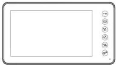
2-MONITOR
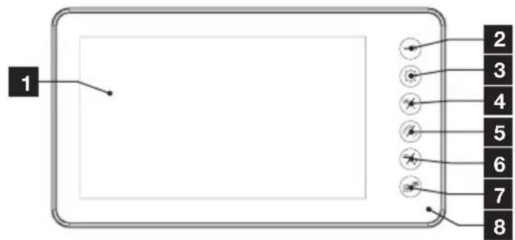
17" LCD screen
2 Lock button: enables an electric lock to be opened
3 MENU button: enables access to monitor settings and photos saved during your absence
4 Left arrow / image button: allows you to decrease the values on the monitor menu, view the intercom panel and end the call
B - PRODUCT DESCRIPTION
| 5 | Right arrow / receiver button: enables the values on the monitor's menu to be increased, enables communication with the visitor. |
| 6 | Entryway / video camera button: enables an electric entryway to be opened |
| 7 | Intercom button: enables communication with a second monitor (ref. 112252) |
| 8 | Microphone |
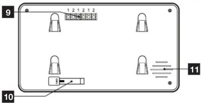
| 9 | Connection terminals |
| 10 | Power supply input |
| 11 | Loudspeaker |
*Subject to availability.
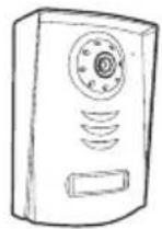
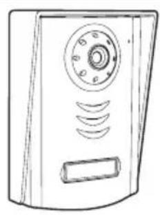
3 - DOORpLATE
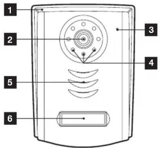
| 1 | Protective hood |
| 2 | Lens |
| 3 | Microphone |
| 4 | Infrared illumination |
| 5 | loudspeaker |
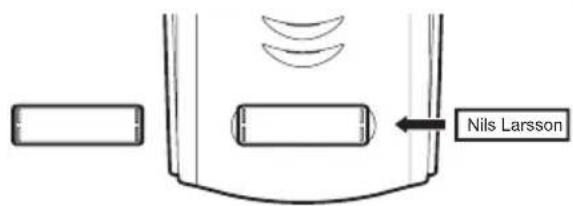
| 6 | Call button, backlit name plate according to the ambient light |
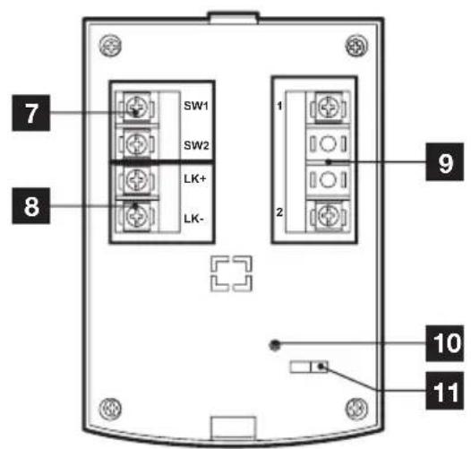
| 7 | Dry contact connection terminal |
| 8 | Electric strike plate connection terminal |
| 9 | Monitor connection terminal |
| 10 | RFID reset button |
| 11 | RFID badge entryway/strike selector switch |
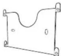
4-WALL bPACKET
The monitor is designed to be fixed to the wall. A wall bracket and the necessary fasteners are included.
5 - MAINs ADApTER
A 230 Vac 50 Hz/17 Vdc 1.5 A mains adapter for powering the monitor is included in the kit. Do not use other power supplies as they could cause irreparable damage to the device and invalidate the warranty. Do not cut or shorten the wire of the mains adapter or the warranty will be void.
C - INSTALLATION
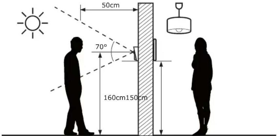
The recommended installation height for the intercom panel is about 160~cm from the ground and 150~cm from the floor for the indoor unit.
WARNING: For obvious safety reasons, the connections must only be made after shutting off the power supply.
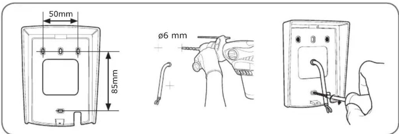
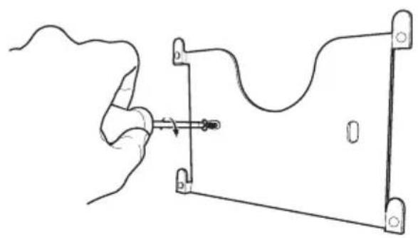
1 - DOORpLATE INsTALLATION
The doorplate must not be directly exposed to bad weather. It should preferably be installed under a porch or covered area.
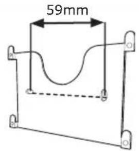
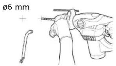
Attach the doorplate hood to your support using the screws and wall plugs suited to the support (the screws and plugs supplied are suitable for solid walls).
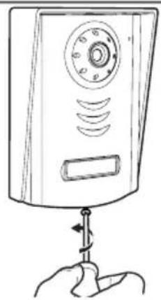
After making the connections on the doorplate (see the connections paragraph), put the doorplate into the hood.
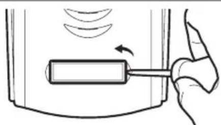
Then screw the doorplate to the hood with the screw provided.

Put on the name label.
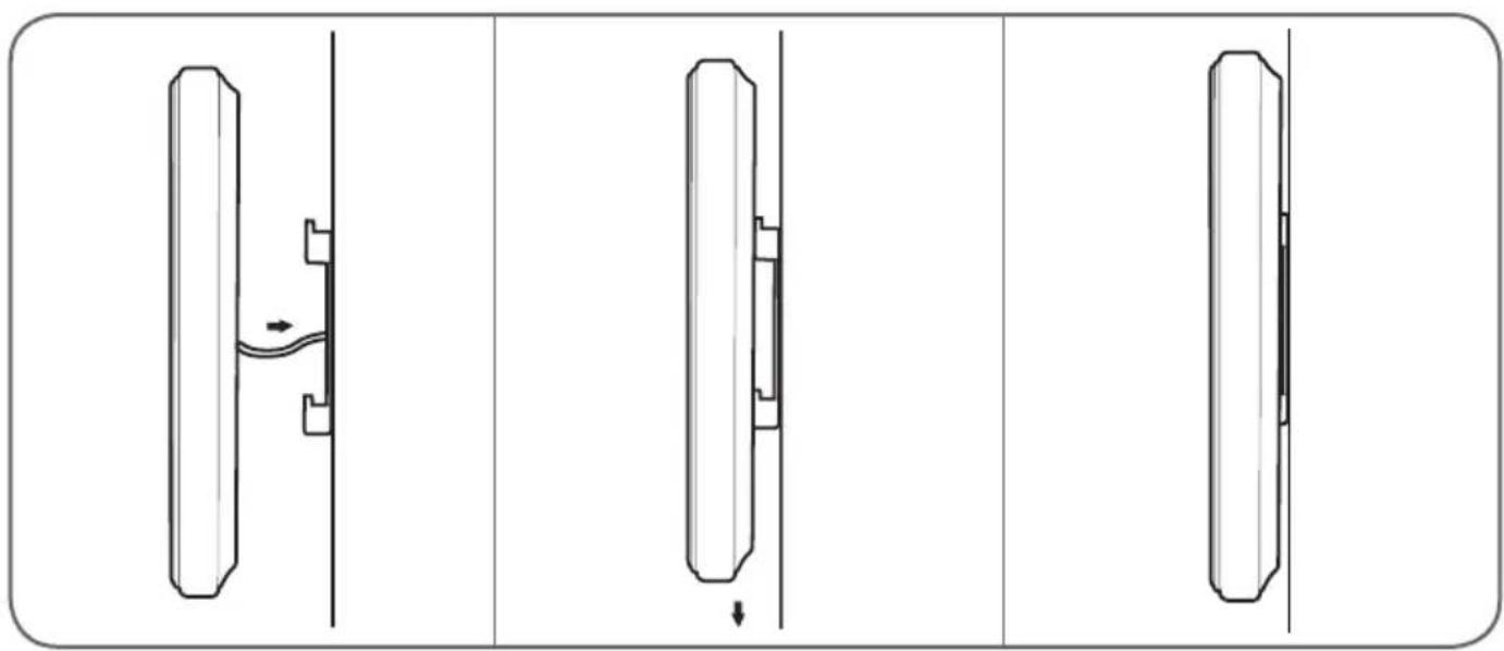
2 - INsTALLING THE MONITOR
Attach the wall mount to the wall using the screws and wall plugs suited to the support (the screws and plugs supplied are suitable for solid walls).
After connecting the monitor (refer to the "connections" paragraph), fit the monitor onto its support.
C - INSTALLATION
3 - CONNECTIONs
- Do not increase the number of insulating screw joints or connectors on the connecting wire between the doorplate and the monitor
- Keep the connecting wire between the doorplate and the monitor more than 50~cm away from any electromagnetic interference (230 V cable, WiFi device, microwave ovens, etc.)
- You can connect and use the electric door release (not provided) with your doorplate, with or without mechanical memory.
between the monitor and the doorplate (100m maximum)
To ensure good audio and video quality, it is advised to not use more than 100m of cable between the intercom and the doorplate. Connect the wires as follows (incorrect wiring can damage the doorplate).
The cable's length determines which cable section is to be used:
| Cable length Section to use | |
| 0 to 50 m 0.75 mm2 | |
| 50 m to 100 m 1.5 mm2 |
between the doorplate and an electric latch (not included)
Use a 12V/0.5A maximum electric latch with or without mechanical memory. For the connection between the doorplate and the door release, use a cable of this kind:
| Cable length Section to use | |
| 0 to 50 m 0.75 mm2 |
between the doorplate and the automated gate (not included)
Section to use: Min. 0.75 mm2
3.1 - CONNECTION BETWEEN THE MONITOR AND THE INTERCOM PANEL
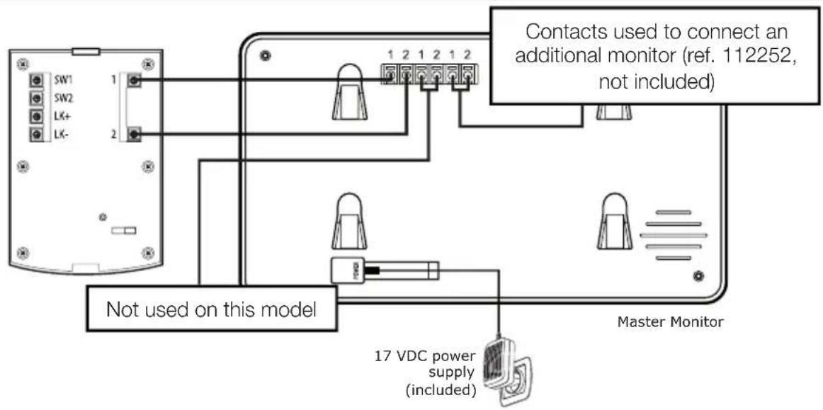
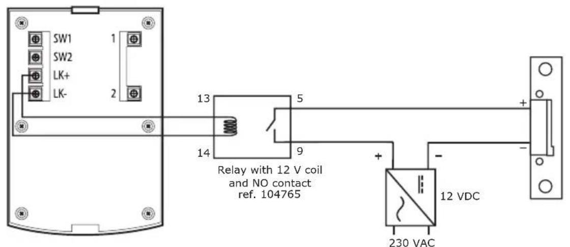
3.2 - WITH ELECTRIC LOCK
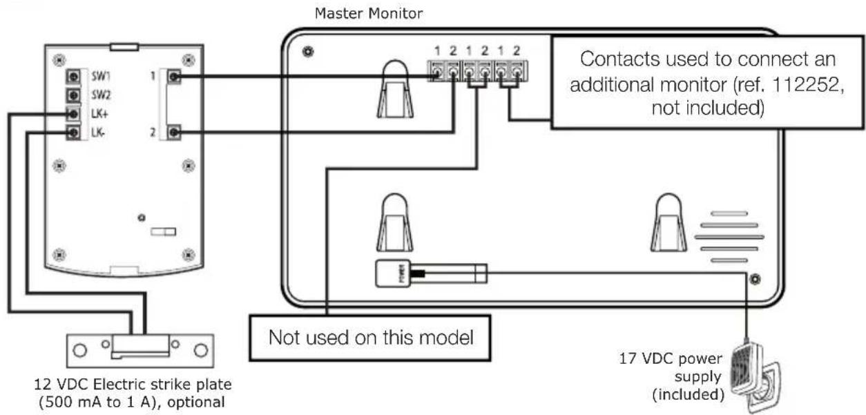
IMpORTANT: if you have trouble opening the lock, which may be caused by a large distance between the screen and the intercom panel, for example, we recommend that you connect it to a separate power supply. If you use a separate power supply, you must connect a 12 V relay (not included) to control it from the video intercom, as illustrated.
C - INSTALLATION
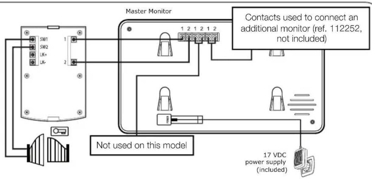
3.3 - WITH AUTOMATIC ENTRYWAY CONTROL
IMpORTANT: connect SW1 and SW2 directly to the opening/closing contact of the automatic control system (automated entryway wired control system input).
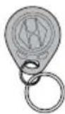
3.4 - ACTIVATING THE BADGES
Three types of badges are included: the red administrator badge, the grey add badge and the blue user badges.
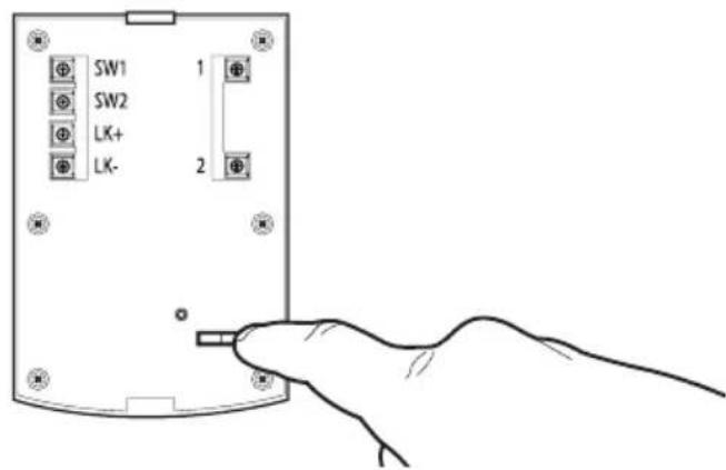
A - INITIALISATION
With the video doorkeeper powered on, press on the "REsET" button on the back of the intercom panel.
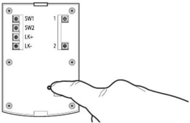
The intercom panel will beep 4 times. Within the next 10 seconds, bring the administrator badge (red) in front of the camera.

Within the next 10 seconds, bring the add badge (grey) in front of the camera.
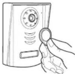
B-ADDING USER BADGES
Bring the add badge (grey) in front of the camera.
The intercom panel will beep 3 times. Within the next 10 seconds, bring one of the user badges in front of the camera.
The intercom panel will beep 1 time.
C - DEACTIVATING ALL BADGES
Hold the administrator badge in front of the camera to deactivate all of the recognized badges. (including the add badge).
D - SELECTING THE ACTION ASSOCIATED WITH THE USER BADGES
At the back of the intercom panel, select the electric strike plate or dry contact output to control one or the other at the swipe of a user badge.
D - USING THE PRODUCT
1 - IDENTIFY AND spEAK TO THE VIsITOR
The visitor presses on the intercom panel's
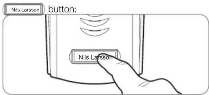
The chime sounds through the monitor's speaker and the intercom panel's video camera is activated. If the visitor is positioned within the camera's field of vision, their image will appear on the monitor for 120 seconds. After 120 seconds, the monitor will return to sleep mode.
To speak with the visitor, press the button. To end the conversation and deactivate the intercom panel, press the button.
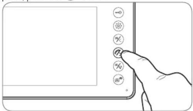
2 - ACTIVATE THE INTERCOM pANEL FROM THE MONITOR
To identify a visitor without them knowing they are being observed or to simply look outside, press the button: the view from the intercom panel will
then appear on the screen for 60 seconds.
If you wish to communicate directly with the outside, press once on the button when the external video camera is displayed.
This particularly useful feature allows you to observe the visitor, even if they haven't pressed the intercom
panel's Nils Larsson button.
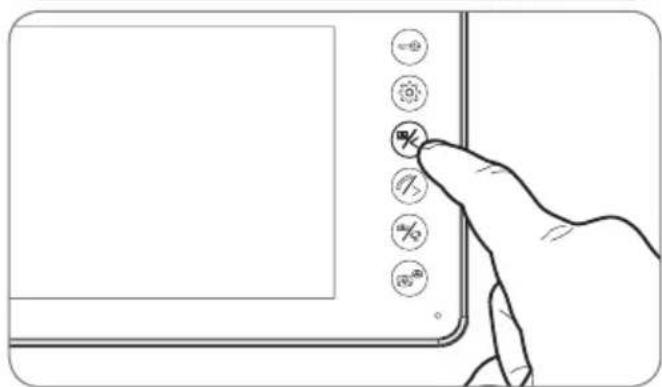
3 - OpENING AN ELECTRIC LOCK AND AN AUTOMATIC CONTROL sYsTEM (OpTIONAL)
If the device is equipped with an electric lock and/or an automatic control system (see "Connection" paragraph), press the button (for the lock) or the button (for the automatic control system) to let a visitor enter.
4 - INTERCOM FEATURE
You can initiate internal communication with the secondary monitor (if present) using the intercom feature. This feature can be used when the monitor is in sleep mode: Press the button on the secondary monitor. You can call the secondary monitor and vice versa. You can answer by pressing the button and communicate for a maximum of 120 seconds. The terminal will then return to sleep mode.
Communication with the intercom panel has priority.
D - USING THE PRODUCT
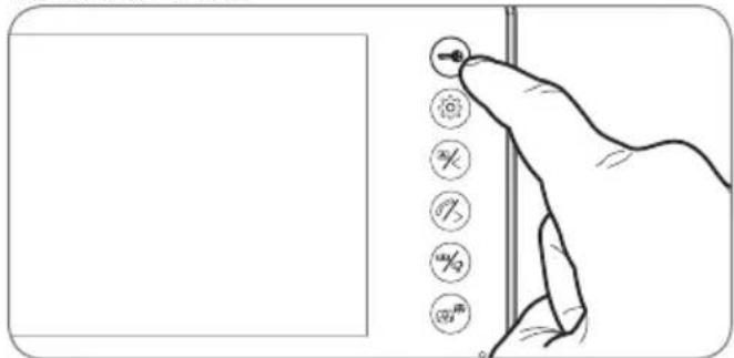
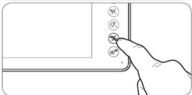
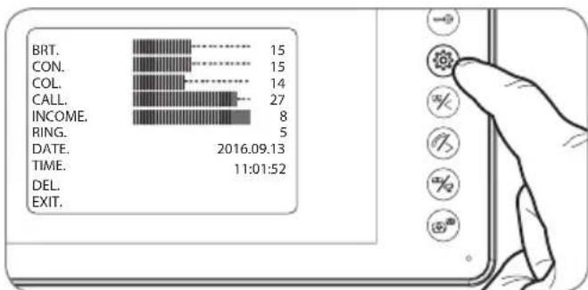
5-MONITOR SETTINGS
With the screen is on, press the button to display the following screen:
Press the button again to browse through the sub-menus (they will light up when selected).
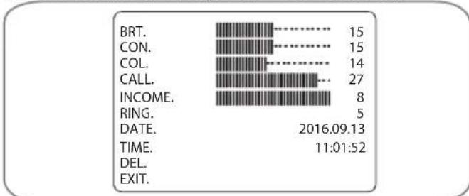
- BRT: Brightness: press the and buttons to
decrease or increase the brightness level of the image.
CON: Contrast: press the 哭 and buttons to decrease or increase the contrast level of the image - COL: Colour: press the and buttons to decrease or increase the saturation level of the image.
- CALL:
Microphone volume: press the 念 and 念 buttons to increase or decrease the microphone volume. - INCOME: Chime volume: press the 0 and 0 buttons to decrease or increase the ring volume.
- RING: Choose the ring tone: press the 念 and 念 buttons to select the desired tone.
COLOURVIDEOINTERCOM
- DATE: Press the 念 and 念 buttons to adjust the highlighted value and the button to switch to the next value. The date and time are indicated on the photos taken during your absence.
- TIME: Press the 念 and 念 buttons to adjust the highlighted value and the button to switch to the next value. The date and time are indicated on the photos taken during your absence.
DEL: To erase all saved photos, press the button. - EXIT: Press the button to close the settings menu.
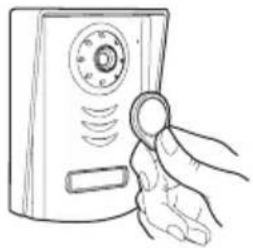
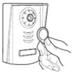
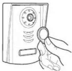
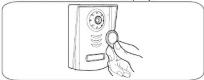
6 - UNLOCKING USING A BADGE
Hold one of the user badges up in front of the intercom panel's camera to unlock the strike plate or the connected automated entryway.
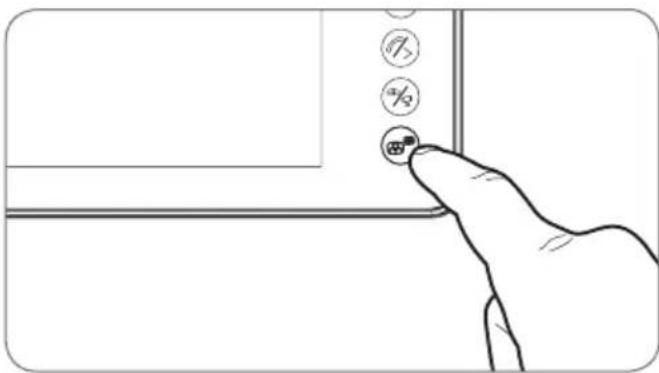
7 - CHECKING PHOTOS TAKEN IN YOUR ABSENCE
Each call causes a photo to be saved. To consult the saved photos, press the button while the screen is off.
E - TECHNICAL AND LEGAL INFORMATION
1 - TECHNICAL CHARACTERISTICS
| MONITOR | |
| Screen | Ultra-flat 7" colour LCD |
| Video standard | PAL/NTSC |
| Resolution | 800 x 3 (RGB) x 480 |
| Power supply | with 230 VAC 50 Hz / 17 VDC 1.5 A mains adapter included |
| Supply voltage | 17 VDC 1.5 A (adapter included) |
| Security | Short circuit and reverse polarity protection |
| Power consumption | from 3.5 W to 11.5 W |
| Transmission system (audio and video) | 2 wires |
| Ideal operating temperature range | -10 °C to 50 °C |
| Max. degree of humidity | 85 % |
| Number of doorbell melodies | 9 |
| Conversation time | automatically shuts off after 2 minutes |
| Dimensions | 275 x 120 x 15 mm |
| Intercom panel | |
| Video camera | CMOS 3003 colour |
| Lens | Fixed-focus / 70° viewing angle |
| Power supply | CC 10-12 V supplied by the monitor |
| Max. consumption | 300 ± 50 mA |
| Brightness | min. 0 lux |
| Night vision | from 0.5 to 1 m |
| Dimensions | 130 x 90 x 24.5 mm |
| Protection rating | IP54 |
E - TECHNICAL AND LEGAL INFORMATION
2 - WARRANTY
- This product is guaranteed for parts and labour for 2 years from the date of purchase. Proof of purchase must be retained for the duration of the warranty period.
- The warranty does not cover damage caused by negligence, knocks, or accidents.
The parts of this product must not be opened or repaired by any persons not employed by Avidsen. - The warranty will be void if the device is tampered with.
- Do not cut or shorten the wire of the mains adapter or the warranty will be void.
3 - HELp AND ADVICE
- If, in spite of the care we have taken in designing our products and drafting these instructions, you do encounter difficulties when installing your product or you have any questions, we urge you to contact one of our specialists who will be glad to help.
- If you encounter operating problems during the installation or a few days afterwards, it is essential that you are in front of your installation when contacting us, so that one of our technicians can diagnose the source of the problem, as it will probably be the result of a setting that is incorrect or an installation that is not to specification.
contact our after sales team on:
0892701369
Monday to Friday, 9AM to 12pM and 2pM to 6pM.
4 - pPRODUCT RETURNS / AFTER sALEs sSERVICE
If, despite the care we have taken in designing and manufacturing your product, it needs to be returned to our customer service centre, you can check the progress of the work on our website at the following address: http://sav.avidsen.com
Avidsen undertakes to keep a stock of spare parts for this product throughout the contractual warranty period.
5 - DECLARATION OF CONFORMITY
Per the RED directive
Avidsen hereby declares that the equipment designated below:
Colour video intercom 112249
Complies with the RED directive and its conformity has been assessed pursuant to the applicable standards in force:
EN 60950-1:2006 + A11:2009 + A1:2010 + A12:2011 + A2:2013
EN 301 489-1 V1.9.2
EN301489-3V1.6.1
EN 300 330-1 V2.1.0
Chambray les Tours, date: 09/01/2016
Alexandre Chaverot, CEO


Picture memory feature
Picture memory feature
Picture memory feature
La placexternamedite3bips.
De segunda a sexta-feira entre as 9h e as 13h e entre as 14h e as 18h.
Picture memory feature
1 - cARATTERISTIcHE TEcNlcHE

- Colour video intercom
- A - SAFETY INSTRUCTIONS 05
- B - PRODUCT DESCRIPTION 06
- C - INSTALLATION 08
- D - USING THE PRODUCT 15
- E - TECHNICAL AND LEGAL INFORMATION 17
- - INTRODUCTION
- Key features:
- - MAINTENANCE AND CLEANING
- A - SAFETY INSTRUCTIONS
- - RECYCLING
- B - PRODUCT DESCRIPTION
- - CONTENTS OF THE KIT
- 2-MONITOR
- - DOORpLATE
- 4-WALL bPACKET
- - MAINs ADApTER
- C - INSTALLATION
- - DOORpLATE INsTALLATION
- - INsTALLING THE MONITOR
- - CONNECTIONs
- between the monitor and the doorplate (100m maximum)
- between the doorplate and an electric latch (not included)
- between the doorplate and the automated gate (not included)
- - CONNECTION BETWEEN THE MONITOR AND THE INTERCOM PANEL
- - WITH ELECTRIC LOCK
- - WITH AUTOMATIC ENTRYWAY CONTROL
- - ACTIVATING THE BADGES
- A - INITIALISATION
- B-ADDING USER BADGES
- C - DEACTIVATING ALL BADGES
- D - SELECTING THE ACTION ASSOCIATED WITH THE USER BADGES
- D - USING THE PRODUCT
- - IDENTIFY AND spEAK TO THE VIsITOR
- - ACTIVATE THE INTERCOM pANEL FROM THE MONITOR
- - OpENING AN ELECTRIC LOCK AND AN AUTOMATIC CONTROL sYsTEM (OpTIONAL)
- - INTERCOM FEATURE
- 5-MONITOR SETTINGS
- COLOURVIDEOINTERCOM
- - UNLOCKING USING A BADGE
- - CHECKING PHOTOS TAKEN IN YOUR ABSENCE
- E - TECHNICAL AND LEGAL INFORMATION
- - TECHNICAL CHARACTERISTICS
- - WARRANTY
- - HELp AND ADVICE
- - pPRODUCT RETURNS / AFTER sALEs sSERVICE
- - DECLARATION OF CONFORMITY
- - cARATTERISTIcHE TEcNlcHE
Brand : AVIDSEN
Model : YLVA 2+ 112249
Category : Intercom