
FHM 301 1TC - Cooker FRANKE - Free user manual and instructions
Find the device manual for free FHM 301 1TC FRANKE in PDF.


| Brand | Franke |
| Model | FHM 301 1TC |
| Product type | Built-in gas hob |
| Number of burners | 3 |
| Burners | Auxiliary (1.00 kW), Rapid (3.00 kW), Triple crown (3.30 kW) |
| Gas supply | Natural gas G20/G25 (20/25 mbar) or LPG G30/G31 (30/37 mbar) |
| Ignition | Integrated electric ignition in knob with thermocouple safety |
| Safety device | Automatic safety valves in case of flame extinction |
| Materials | Stainless steel and enamel |
| Cleaning | Soapy water, non-abrasive sponge; do not use steel wool or steam cleaners |
| Burner maintenance | Cleaning with warm soapy water (not in dishwasher) |
| Total thermal power | 7.30 kW |
| Electrical supply | 220-240 V ~ 50/60 Hz |
| Power consumption | Low (only for ignition) |
| Installation class | Class 3 (built-in) |
| Gas connection | Rigid copper tube ∅12 mm or flexible steel, sealing gasket supplied |
| Electrical connection | Three-pole cable 3×1.5 mm² type H05VV-F |
| Injectors | Pre-set for natural gas; LPG injector kit supplied as standard |
| Minimum power adjustment | Adjustment screw accessible after removing knobs |
| Built-in dimensions | See the manual (not specified here) |
| Target countries | France, Belgium (specific standards) |
| Standards | CE, gas directives (90/396/EEC), low voltage (73/23/EEC), EMC (89/336/EEC) |
Frequently Asked Questions - FHM 301 1TC FRANKE
User questions about FHM 301 1TC FRANKE
0 question about this device. Answer the ones you know or ask your own.
Ask a new question about this device
Download the instructions for your Cooker in PDF format for free! Find your manual FHM 301 1TC - FRANKE and take your electronic device back in hand. On this page are published all the documents necessary for the use of your device. FHM 301 1TC by FRANKE.
USER MANUAL FHM 301 1TC FRANKE
User and installation instructions 10
Built-in hob

Introduction 10 A close view. Use 12 Hob cleaning and maintenance 12 Support 13 Safety warnings 13 Installation 15 Connection to the gas supply. 16 Electrical connection 17 Replacing injectors 17 Minimum flame adjustment 17 Technical data 18
Introduction
Thank you for choosing a Franke product. Before using the appliance, please read all the instructions and advice contained in this manual. In this way you will be able to make best use of the appliance and also ensure its lasting efficiency. Keep this booklet for further reference.
A close view
A Control Panel B Hobs
A Control panel FHM 301 ITC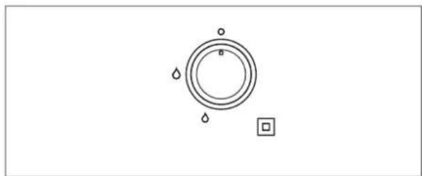
Control panel FHM 302 2G
B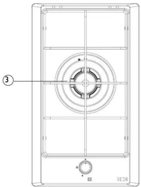
FHM 302 2GFHM 301 ITC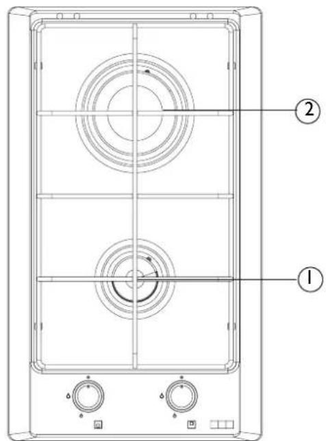
1) Auxiliary 2) Rapid 3) Triple crown
Lighting the burners
The control knobs on these models incorporate the ignition and safety device. To light the burners, proceed as follows:
- Turn the required knob.
- Keep the knob pressed down for 3-4 seconds to allow the sparks to ignite the gas as it comes out the flame-spreader and to allow the thermocouple to heat up.
- After 3-4 seconds, release the knob and turn it anti-clockwise to adjust the flame to the required setting. If the flame goes out, repeat the operation from step 1.
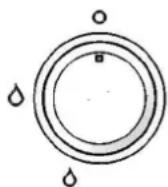
Symbols
Circle: closed;
large flame maximum gas delivery;
small flame minimum gas delivery.
Burner use
For better efficiency and lower gas consumption, use pots of suitable width for the burners, making sure the flame does not extend beyond the edges (respect the table).
Automatic safety valve
This safety device automatically closes the gas cock in the event one of the burners goes out accidentally as a result of draughts, a pot spilling over, or a temporary interruption of the gas supply. This device intervenes approximately 30 seconds after the flame has gone out.
Hob cleaning and maintenance
Before carrying out any hob cleaning or maintenance, always unplug the appliance or disconnect the power by means of the main switch.
- Stainless steel and enamelled parts will remain pristine if regularly cleaned with water or using specific products, and thoroughly drying them afterwards.
- To restore the original lustre, periodically use Franke's special stainless-steel cleaner and microfibre cloth, available from your retailer or the Franke After-sales Service.
- NEVER use scouring pads, steel wool, muriatic acid or other products which could scratch or mark the surface. Do not use steam cleaners.
- Do not leave acid or alkaline substances or rusty iron items on the hob.
- Remove any food residues deposited during cooking as soon as possible.
- The burners and flame-spreaders can be removed from the hob and cleaned with hot soapy water (DO NOT place in dishwasher); dry thoroughly after cleaning. Make sure the gas outlet zones are perfectly clean.
- The natural colour of the pot grids, in the pot placing section, may alter over time as a result of heat. To clean the pot grids, proceed as with the burners.
In case of possible operating problems, contact a Franke Service Centre (see attached list). Never make use of unauthorised technicians.
Specify:
- Type of fault;
- Appliance model (Art.);
- Serial number (S.N.);
This information is given on the appliance dataplate on the warranty certificate.
Safety warnings
Always contact qualified personnel in the following cases:
- installation (see installation section); -doubts regarding operation.
Contact an Authorised Service Centre in the following cases:
- immediately after unpacking, in case of doubts about the condition of the appliance;
- replacing or damaged power cable;
- appliance malfunction or poor operation, requesting original spare parts.
General instructions
To ensure safe and efficient operation of this appliance: - only contact authorised service centres; - always demand the use of original spare parts; - the appliance is designed for non-professional, domestic use; do not modify its characteristics; - the dataplate gives the symbols indicating the countries for which the instructions apply; - appliance electrical safety is guaranteed only when it is connected to an earthing system in compliance with the current regulations; - do not touch the pot grids during use, since they become very hot. Keep children away from the appliance; - only use the appliance for cooking food; - before any cleaning or maintenance operations, or in case of malfunction, disconnect the appliance from the mains power supply; - always check that the control knobs are in the off position when the appliance is not in use.
Do not allow children to touch:
- the controls and the appliance in general;
- the packing elements (bags, polystyrene, staples, etc.);
- the appliance, during and immediately after use, since the hob becomes very hot;
- an unused appliance (make any potentially hazardous parts safe).
Do not:
- touch the appliance with wet parts of the body;
- use the appliance when barefoot;
- pull the appliance or power cable to unplug it;
- carry out improper or hazardous operations;
- leave the power cables of other electric appliances on hot parts of the appliance;
- expose the appliance to atmospheric agents;
- use the appliance as a support top;
- use flammable liquids near the appliance;
- use adapters, multi-sockets or extension leads;
- allow anyone except qualified personnel to install or repair the appliance.
Important
- Do not place unstable or deformed pots on the burners, since they may tip over or cause spills.
- If the appliance has a lid, make sure the burners are cold before closing it.
- Close the gas cock when the hob is not in use.
- Before installation, make sure the gas supply is compatible with appliance specifications. The type of gas for which the appliance is arranged is specified on the dataplate on the bottom of the drawer. This appliance is not connected to a fume extraction device and must be installed and connected in compliance with the current regulations. Pay particular attention to the applicable regulations on ventilation. The use of a gas cooking appliance produces heat and humidity in the room where it is installed. Ensure the room is adequately ventilated: keep natural ventilation openings open, or install a mechanical ventilation device (extractor hood with exhaust duct). In case of intensive or prolonged use of the appliance, it may be necessary to provide additional ventilation, for example by opening a window, or more efficient ventilation, by increasing the extractor hood speed.
The manufacturer declines any liability for damage or injury due to: incorrect installation, improper, incorrect or unreasonable use.
Detailed below are all the procedures to be followed for the installation of your appliance, including gas and electrical connections. These procedures must be carried out exclusively by a qualified technician, in accordance with current regulations, since installation by an unqualified person may constitute a health hazard.
The manufacturer declines all liability for injury to persons or animals or damage to property resulting from failure to comply with these regulations. The gas connection must conform to the current legislation in the country at the time of installation.
Preparing the cabinet
This handbook refers to a class 3 built-in hob.
Prepare the opening in the top according to the measurements given in fig. I in case of combined installation of more than one cooking hob, or according to the diagram in fig. 2 in case of single installation.
In any case, it is essential to make the opening in the most convenient position, bearing in mind that the gas pipe must not come into contact with the sides of a possible oven under the hob.
COMBINED INSTALLATION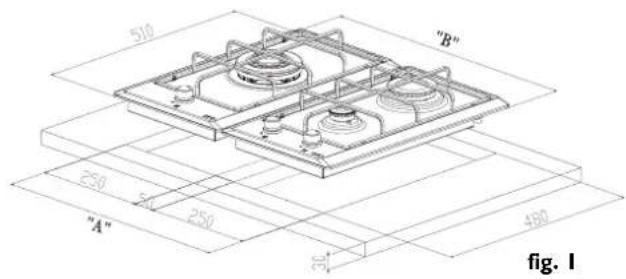
SINGLE INSTALLATION fig. 2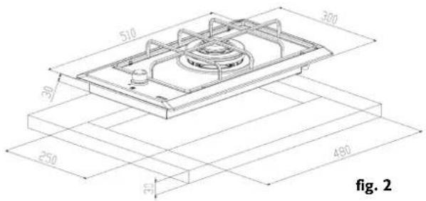
Opening for 2 hobs Domino FHM "A" = 550mm ("B" = 600mm)
Opening for 3 hobs Domino FHM "A" = 850mm ("B" = 900mm)
Opening for 4 hobs Domino FHM "A" = 1150mm ("B" = 1200mm)
In case of combined installation of more than one cooking hob it is advisable to make a separate opening for each hob, leaving a 50 mm strip between each opening. In this way the hobs will be next to each other without any spaces.
To fit the hobs with spaces between them (recommended min. 10 mm), the width of the strip on the cabinet must be 50 mm plus the space required between hobs.
Fitting in the cabinet
After carrying out the necessary connections, position the sealing strip all around the cutout and fit the hob. Carefully tighten the fixing hooks. Remove any excess sealing strip.
Important
These are "Y"-type appliances regarding protection rating against the risk of fire, and can therefore be installed near wooden walls higher than the tops in which they are installed, provided the following minimum distances from the edges of the appliances are maintained: 50 mm for side walls, 30 mm for the rear wall; any wall units above must be at least 700 mm from the hob.
If there are drawers under the cooking hob, it is advisable to insert a separator plate (with suitable openings made for the electrical/gas connections) so that the items in the drawer do not come into contact with the bottom part of the hob.
Connection to the gas supply
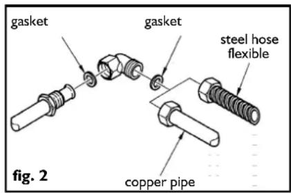
Check that the appliance is suited to the gas type before connecting it to the gas supply in conformance with current legislation. If this is not the case, carry out the operations described in the paragraph on "replacing injectors" (page 17). For a liquid gas supply use pressure regulators which comply with current legislation. Connection to the gas supply may be made in two ways:
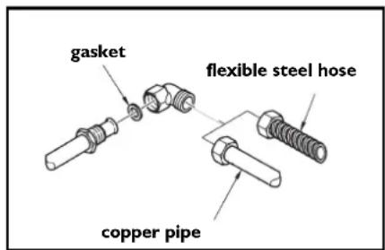
A Connect the gas hob using a 12 mm diameter rigid copper pipe, as shown in fig. 2. To prevent any risk of leaks, use the rubber gasket supplied. B Connect the hob using a continuous-surface steel hose. Once again, in this case, prevent any risk of leaks by using the gasket supplied. Note that installation must be carried out in compliance with current regulations pertaining to gas installations.
Having completed the connection to the gas supply, use soapy water to check the connection for leaks.
For United Kingdom, Northern Ireland and Republic of Ireland
Ventilation of installation area
Make sure that the room where the appliance is installed has permanent ventilation openings on an outside wall or ventilation ducts, in order to ensure adequate air flow as prescribed by current legislation. All openings must:
1. have a minimum working section of 100 cm²; 2. be made in such a way as to prevent them being blocked in any manner, from inside or outside; 3. be provided with suitable protection to ensure the size of the ventilation opening is not reduced; 4. be positioned at such a height from floor level as not to interfere with the discharge of combustion fumes.
If openings are made in the wall of an adjacent room, the latter must have direct ventilation and must not be:
1. a bedroom; 2. a common area of the building in question; 3. a fire hazard area.
Before testing and inspecting the appliance check that the adjacent room, which shares the wall in which the ventilation opening has been made, does not have low pressure due to another user; moreover, ensure adequate air flow between the two rooms is guaranteed by permanent, unobstructed openings, for example by increasing the gap between the bottom of the door and the floor. Discharge of combustion products must be guaranteed by means of a hood which, in turn, must be connected to a chimney, a flue, or directly to the outside.
Accessing the hob
To access the box containing the functional parts, proceed as follows:
- remove the grids, burner caps and flame-spreaders;
- remove the knobs, pulling them off their pins;
- remove the screws that fix the burners to the hob;
- lift the hob.
Electrical connection
The FRANKE cooking hob comes with a 3-core power cable with free terminals.
If the hob is permanently connected to the power supply, install a circuit breaker having a contact opening distance (at least 3 mm) that allows complete disconnection in the conditions of overvoltage category III. Make sure:
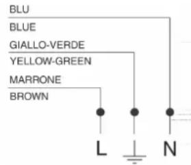
a) the plug and socket are suitable for a 16A current b) both are easily accessible and positioned so that no live part can be accessed when inserting or removing the plug c) the plug can be inserted without difficulty d) that when the plug is inserted, the hob is not resting on it when installed in the cabinet e) the terminals of two appliances are not connected to the same plug f) if the power cable needs to be replaced use a 3 x 1.5 mm² cable type H05VV-F
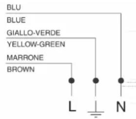
g) to respect the polarities of the free terminals (Brown=Live Blue=Neutral Yellow/Green=Earth)
NB: Make sure the characteristics of your household electrical system (voltage, maximum power and current) are compatible with those of your FRANKE hob.
Replacing injectors
NB: All the appliances are factory-set for G20 natural gas (methane).
If a different type of gas is to be used, change the injectors as follows:
1. remove the grids, burner caps and flame-spreaders; 2. unscrew and remove the injectors and replace them with those supplied, suitable for the gas supply, making sure the marking matches that given in the table (page 18); 3. refit the flame-spreaders, burner caps and grids; 4. these burners do not require air adjustment.
Important
When converting the appliance to a different type of gas, place the corresponding self-adhesive label (supplied as an accessory) in the special space on the dataplate. For operation with LPG (G30 or G31), the minimum flame screw must be fully screwed down. These appliances are supplied in cat. II 2H3+
Minimum flame adjustment
- Remove the knobs (push-on type).
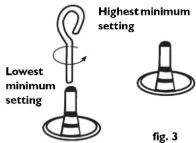
- Light the burners and adjust the minimum flame by turning the adjustment screw clockwise to reduce the flame and anticlockwise to increase it (fig. 3). The screwdriver for adjustment is supplied with the accessories.
Appliance cat. II 2H3+
| Type of gas Burner | Injector marking | Rated heat capacity in kW | Heat capacity reduced in kW | Rated consumption |
| Natural gas (methane) | auxiliary | 72 | 1.000 | 0.380 |
| rapid | 115 | 3.000 | 0.800 | |
| G20 | triple crown | 140 | 3.300 | 1.600 |
| 20 mbar | ||||
| Liquified petroleum gas | auxiliary | 50 | 1.000 | 0.380 |
| rapid | 85 | 3.000 | 0.800 | |
| (LPG) | triple crown | 91 | 3.300 | 1.600 |
| G30-G31 | ||||
| 30/37 mbar | ||||
| Table of recommended pots | ||||
| Burner Ø Pots in cm | ||||
| Auxiliary | from Ø 8 to Ø 14 | |||
| Rapid | from Ø 22 to Ø 24 | |||
| Triple crown | from Ø 24 to Ø 28 | |||
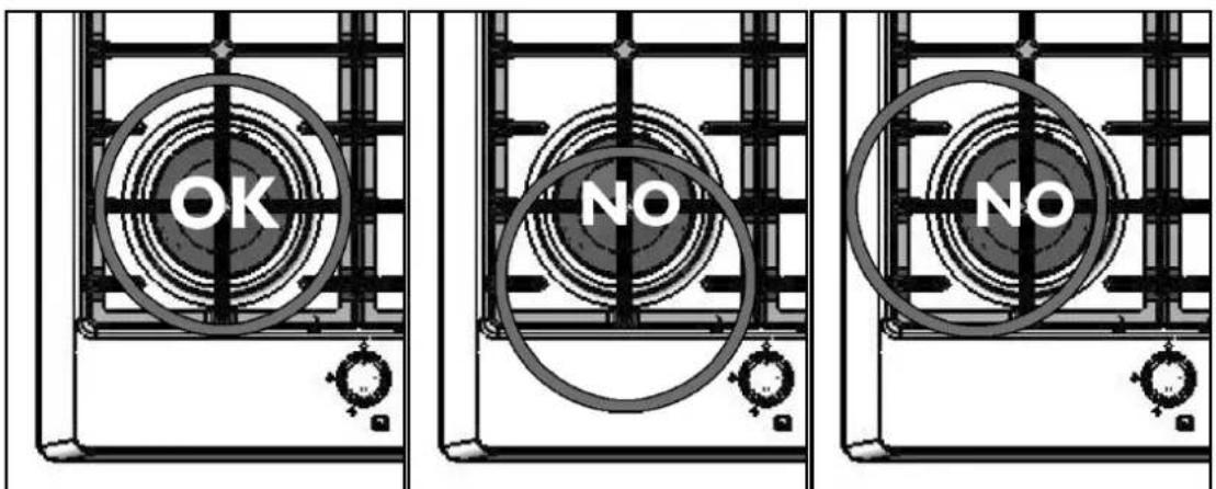
The use of larger pots than those specified can cause excessive overheating of the knobs and top. Franke declines any liability for damage due to such incorrect use.
Total heat capacity: see dataplate on the bottom of the hob.
Air necessary for combustion: 2m3 /h per kW of installed power - see dataplate.
Power supply voltage 220/240 V 50-60 Hz.
C
The appliance complies with the following EEC Directives:
-90/396/EEC (Gas): - 73/23/EEC dated 19/02/73 (Low Voltage); - 89/336/EEC dated 03/05/89 (Electromagnetic Compatibility); - 93/68/EEC dated 22/07/93 as amended.
Sommaire
Doctyn K Bapouhno nanei
Длядоступа к внутренним частям панели действуйте следующим образом:
- Снимите решетки, крышки и рассекатели горелок;
- Снимите ручки с соответствующих стержней;
- Снимите винты крепления горелок к панели;
- Remove the panel.
Connection to the electrical mains.
The FRANKE oven is supplied with a three-core power cable, the ends of which are free.
In the case of a fixed connection of the oven to the electrical mains, it is necessary to provide a device for disconnecting from the mains with a contact opening distance (at least 3 mm), ensuring complete disconnection of the appliance from the mains under overvoltage category III conditions. Check the following:
a) The plug and socket must be rated for a current of 16 A. b) The plug and socket must be easily accessible and installed so as to exclude the possibility of contact with parts under voltage when connecting or disconnecting the plug. c) The plug must insert without the use of force. d) After inserting the plug into the socket, the oven must not rest on it when built into the furniture. e) Only one appliance must be connected to a single socket. f) In case of replacement of the power cable, use a cable of type H05VV-F with a cross-section of 3 x 1.5 mm2.
g) When connecting the free ends of the cable, the correct polarity must be observed (Brown = Phase, Blue = Neutral, Yellow-Green = Earth).
NOTE: Make sure that the characteristics
of your home electrical system (voltage, maximum power and current)
match the rated characteristics of the FRANKE oven you have purchased.
Replacing the injectors
Warning. All products manufactured by the factory are set to operate with natural gas (G20).
If using a different gas, replace the injectors as follows:
- Remove the grates, burner caps and flame spreaders;
- Unscrew and remove the injectors; replace them with injectors suitable for the type of gas used, checking that their markings match those indicated in the table (page 6); 3. Replace the flame spreaders, caps and grates;
- These burners do not require adjustment of the air supply.
In case of conversion of the appliance to another gas type, at the point provided for this purpose on the appliance, it is necessary to affix the corresponding adhesive label supplied as an accessory. When operating on liquefied petroleum gas (G30 or G31), the minimum flame adjustment screw must be fully tightened. These appliances comply with category II 2H3+.
Minimum flame adjustment
- Remove the knobs (push-on type).
- Light the burner, then adjust the minimum flame by turning the adjustment screw clockwise to decrease the flame, or counterclockwise to increase it (Fig. 3). The screwdriver for this adjustment is included in the kit supplied with the panel version of the appliance.
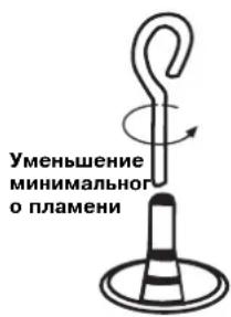
Increasing the minimum flame Fig. 3
Appliance category II 2H3+
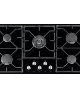
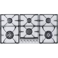
- INTRODUCTION
- A CLOSE VIEW
- LIGHTING THE BURNERS
- SYMBOLS
- BURNER USE
- AUTOMATIC SAFETY VALVE
- HOB CLEANING AND MAINTENANCE
- SPECIFY
- SAFETY WARNINGS
- ALWAYS CONTACT QUALIFIED PERSONNEL IN THE FOLLOWING CASES
- CONTACT AN AUTHORISED SERVICE CENTRE IN THE FOLLOWING CASES
- GENERAL INSTRUCTIONS
- DO NOT ALLOW CHILDREN TO TOUCH
- DO NOT
- IMPORTANT
- PREPARING THE CABINET
- FITTING IN THE CABINET
- CONNECTION TO THE GAS SUPPLY
- FOR UNITED KINGDOM, NORTHERN IRELAND AND REPUBLIC OF IRELAND
- VENTILATION OF INSTALLATION AREA
- ACCESSING THE HOB
- ELECTRICAL CONNECTION
- REPLACING INJECTORS
- MINIMUM FLAME ADJUSTMENT
- C
- SOMMAIRE
- DOCTYN K BAPOUHNO NANEI
- CONNECTION TO THE ELECTRICAL MAINS
- REPLACING THE INJECTORS
Brand : FRANKE
Model : FHM 301 1TC
Category : Cooker