
WMR300A - Weather Station OREGON SCIENTIFIC - Free user manual and instructions
Find the device manual for free WMR300A OREGON SCIENTIFIC in PDF.
User questions about WMR300A OREGON SCIENTIFIC
0 question about this device. Answer the ones you know or ask your own.
Ask a new question about this device
Download the instructions for your Weather Station in PDF format for free! Find your manual WMR300A - OREGON SCIENTIFIC and take your electronic device back in hand. On this page are published all the documents necessary for the use of your device. WMR300A by OREGON SCIENTIFIC.
USER MANUAL WMR300A OREGON SCIENTIFIC
Ultra-precision Professional Weather System
Model: WMR300 / WMR300A
USERMANUAL
CONTENTS
Introduction 1
Packaging Contents 1
Display Unit 1
Solar Transmitter 1
Rain Gauge 1
Temperature & Humidity Sensor 2
Wind Sensor 2
Assembly Part 2
Accessories - Sensors 2
Overview 2
Main Unit 2
Transmitter Box 2
Rain Gauge 3
Temperature & Humidity Sensor 3
Wind Sensor 3
Detailed LCD Display 3
LCD Display 3
Indoor Temperature & Humidity 3
Outdoor Temperature & Humidity 4
Dew Point / Heat Index / Wind Chill 4
Sunrise/Sunset 4
Wind Speed/Wind Direction 4
Clock / Alarm / Weather Forecast / Moon Phase 4
BarChart 4
Barometer 5
Rainfall 5
Installation 5
Set up Rain Sensor & Thermo / Hygro Sensor 5
Set up Wind Sensor 5
Set up Transmitter Box 5
Cable Connections 5
Transmitter Box-Battery Installation 6
Channel Setting 6
Remove Setting 6
LED Light Indicator 6
Sensors Installation 6
Main Unit-Batteries Installation. 7
Pairing Sensors / Remove Sensors 7
Clock 7
Manually Set Clock 7
Clock Reception 8
Alarm Clock 8
Moon Phase 8
Weather Forecast 8
Temperature and Humidity 8
Dewpoint / Heat Index / Wind Chill 8
Sunrise/Sunset 9
Wind 9
Direction Calibration 9
Wind Speed / Direction 9
Barometric Pressure 9
Rainfall 9
Accumulated Rainfall 9
BarChart 9
Memory 10
Max / Min of Today / Monthly Records 10
Hourly Records 10
Data Log 10
Alarm 10
Backlight 11
Reset 11
Maintenance 1
To Maintain the Thermo / Hygro Sensor. 11
Trouble Shooting 17
Precautions 11
Specifications 12
About Oregon Scientific 13
EU-declaration of Conformity 13
FCC Statement 13
Declaration of Conformity 13
INTRODUCTION
Thank you for selecting the Oregon Scientific™ Ultra-precision Professional Weather System (WMR300 / WMR300A).
This system can provide you with weather information through several sensors with high level of accuracy. All sensors are cabled to a transmitter box which is battery and solar powered operated for wirelessly communicating and displaying the data on an indoor LCD main unit.
This system remembers the data for a time range for you to monitor and analyze the weather status. You can also export the data to PC by cable and manage and analyze the data systematically.
The system can expand up to 8 thermometer & humidity sensors and be compatible with other weather sensors. To purchase additional sensors, please contact your local retailer.
NOTE Please keep this manual handy as you use your new product. It contains practical step-by-step instructions, as well as technical specifications and warnings you should know about.
PACKAGING CONTENTS
DISPLAY UNIT
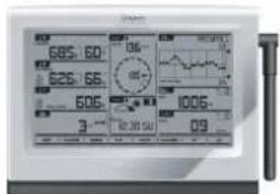
1 x Main unit
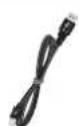
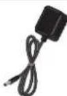
1xUSB cable 1xPower adapter
Power adapter
3 x C 1.5V battery
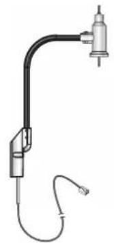
SOLAR TRANSMITTER
1 x Solar transmitter
(STC300/300A)
1 x Mounting insert

1xAA1.2V
rechargeable battery
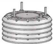
RAIN GAUGE
1 x Rain collector
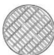
1 x Plastic debris filter
1 x Rain gauge
(PCR300)
1 x Backing metal plate
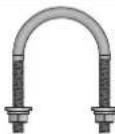
1xU-bolt
(with 2 x lock washer
& 2 x flat washer & 2 x hex nut)
1 x Thermo/hygro casing with sensor installed (THGN300)
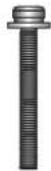
3xScrews (Type B,with 3x lock washer &3xflatwasher)
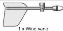
WIND SENSOR
1 x Wind sensor unit (WGR300)
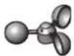
1 x Wind cups
4 x Nylon cable tie
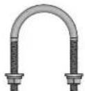
1xU-bolt (with 2 x lock washer & 2 x flat washer & 2 x hex nut)
ASSEMBLY PARTS
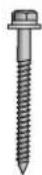
2x Screws (Type A, with 2 x lock washer & 2 x flat washer)
1 x Screw driver
ACCESSORIES - SENSORS
The system can expand up to 8 thermometer & humidity sensors and be compatible with other weather sensors. Optional wireless remote sensors (coming soon) such as those listed below can be purchased separately. For more information, please contact your local retailer.
- Wireless repeater (Expand the transmission range)
- UV sensor (UV index & UV dose)
Solar radiation sensor (Solar radiation, THSW & Evapotranspiration (ET)) - Aspirated fan (Increase accuracy of temp/humidity sensor)
- Soil/Leaf sensor (Soil moisture/temperature & Leaf wetness)
- Features and accessories will not be available in all countries.
OVERVIEW
MAIN UNIT
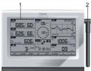
Figure 1 - Front View
- LCD display
- Antenna
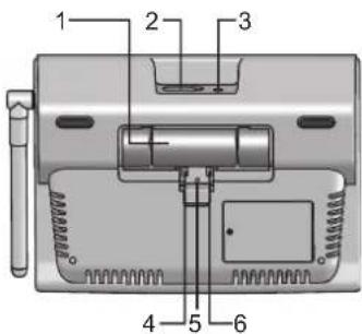
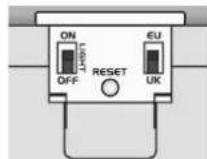
Figure 2 - Back View
- Battery compartment
- USB socket
- Power adapter socket
- Backlight (continuous) slide switch ON/OFF
- RESET: Reset unit to default settings
- EU/UK slide switch (WMR300 only)
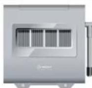
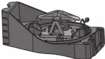
TRANSMITTER BOX
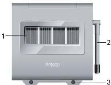
Figure 3 - Front View
- Solar panel
- Antenna
- Screw holes
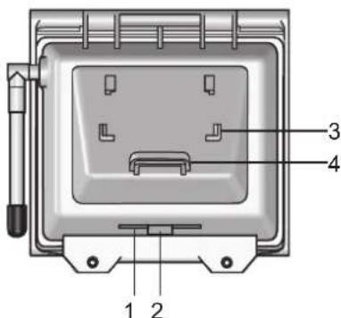
Figure 4 - Back View
- Cable slot
- Rubber stopper
- Mounting bracket
- Mounting ring
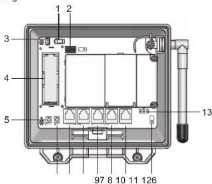
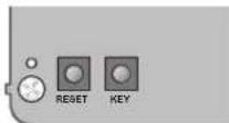
Figure 5 - Inside View
- Power adapter socket (optional)
- Channel setting slide switches (SW1)
- Color-coded connector for connecting solar panel
- Rechargeable battery compartment
- RESET button
- KEY button: for wind direction calibration
- UV sensor socket (not available now)
- SOLAR sensor socket (not available now)
- RAIN sensor socket
- TH (temperature & humidity sensor) socket
- WIND sensor socket
- Pairing slide switch (SW4)
- LED lights (blue/green/red)
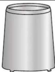
RAIN GAUGE
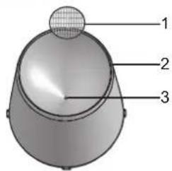
Figure 6 - Top View
- Plastic debris filter
- Rain collector
- Collector hole
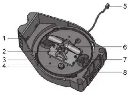
Figure 7-Bottom View
- Screw holes
- Rain sensor
- Rain collector installation hole
- Balance indicator
- Sensor cable
- Tipping bucket
- Drain holes
- Hole for mounting insert
TEMPERATURE & HUMIDITY SENSOR
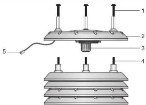
Figure 8
- Screws (Type B)
- Sensor casing
- Temperature and humidity sensor
- Screws (pre-installed)
- Sensor cable
WIND SENSOR
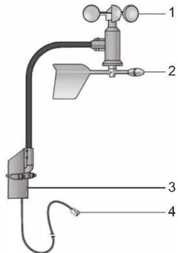
Figure 9
- Wind cups (anemometer)
- Wind vane
- Wind sensor holder
- Sensor cable
DETAILED LCD DISPLAY
LCD DISPLAY
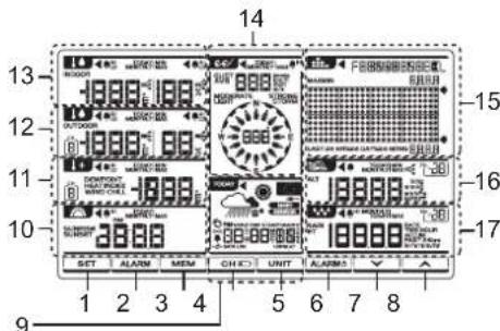
- Ener setting modes
- : See and view status of clock and HI/LO alarms
- Current reading and memory.
- / Toggle between 8 different channels / low battery indicator
- CHNTgeldisplay/measurement units
- 4mm厚 on or off
- : Press to decrease value
- : Press to increase value
- 104y alarm / weather forecast / moon phase
- Sunne/ sunset area
- Dew point / heat index / wind chill area
- 10 temperature and humidity area
- temperature and humidity area
- speed/direction area
- 1
- 2011, 1994, 2005, 2008, 2010, 2013
- 11 area
INDOOR TEMPERATURE & HUMIDITY
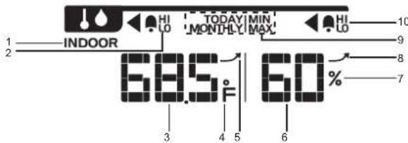
- Indoor temperature/humidity indicator
- I/LO alarm: Alarms for high or low indoor temperature
- Indoor temperature reading
- 'C / 'F: Temperature unit
- Indoor temperature trend
- Indoor humidity reading
- %:Humidity unit
- Indoor humidity trend
- TODAY/MONTHLY/MIN/MAX: Display the maximum/minimum of today's/ monthly indoor temperature / humidity reading
- HI/LO alarm: Alarms for high or low indoor humidity
OUTDOOR TEMPERATURE & HUMIDITY
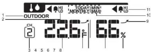
- Outdoor temperature/humidity indicator
- I/LO alarm: Alarms for high or low outdoor temperature
- Selected channel
- Outdoor temperature reading
- 'C / 'F: Temperature unit
- Outdoor temperature trend
- Outdoor humidity reading
- %: Humidity unit
- Outdoor humidity trend
- TODAY/MONTHLY/MIN/MAX: Display the maximum/minimum of today's/ monthly outdoor temperature / humidity reading
- HI/LO alarm: Alarms for high or low outdoor humidity
DEW POINT / HEAT INDEX / WIND CHILL
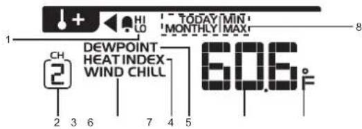
- I/LO alarm: Alarms for high or low temperature
- Selected channel
- Wind chill indicator (From CH1 reading only)
- Heat index indicator
- Dew point indicator
- Dew point / heat index / wind chill temperature
- C/F: temperature unit
- TODAY/MONTHLY/MIN/MAX: Display the maximum/minimum of today's monthly dew point/heat index/wind chill reading
SUNRISE/SUNSET

- AM/PM
- Sunrise indicator
- Sunset indicator
- Time display
WIND SPEED/WIND DIRECTION
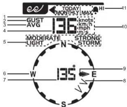
- TODAY/MONTHLY/MAX: Display the maximum today's / monthly gust wind reading
- Gust wind indicator
- Average wind indicator
- Wind speed reading
- MODERATE/LIGHT/STRONG/STORM: Wind speed level indicators
- W(West) / S(South) / E(East) / N(North)
- Wind direction reading/calibrated angle reading
- Wind direction indicator(s) during last 1 hour
- Gust / average wind direction indicator
- Knots / km/h / mph / m/s: Wind speed unit
- HI alarm: Alarms for high wind speed
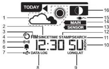
CLOCK / ALARM / WEATHER FORECAST/ MOON PHASE
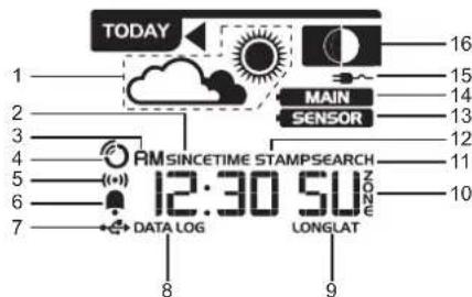
- Weather forecast icon area
- SINCE: Start date of the accumulated rainfall
- AM/PM
- RF clock signal reception indicator
- Alarm display mode
- Daily alarm indicator
- USB port is successfully connected
- DATA LOG: Data log information displays
- LONG/LAT: Longitude/Latitude
- Time zone offset
- SEARCH: Searching for solar transmitter
- TIME STAMP: Particular time of the selected memory
- Solar transmitter is low battery
- Main unit is low battery
- Power adapter is connected
- Moon phase area
BAR CHART
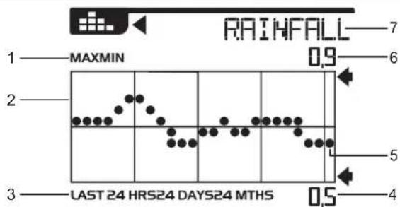
- MAX/MIN: Maximum/minimum reading indicator of selected area
- Bar chart area
- LAST 24HRS/24DAYS/24 MTHS: Time range
- Minimum reading for reference
- Current graph reading of the corresponding area
- Maximum reading for reference
- IN TEMP/IN HUM/OUT TEMP/OUT HUM/DEWPOINT/HEAT INDEX/WIND CHILL/WIND/BARO/RAINFALL: Chart mode indicators
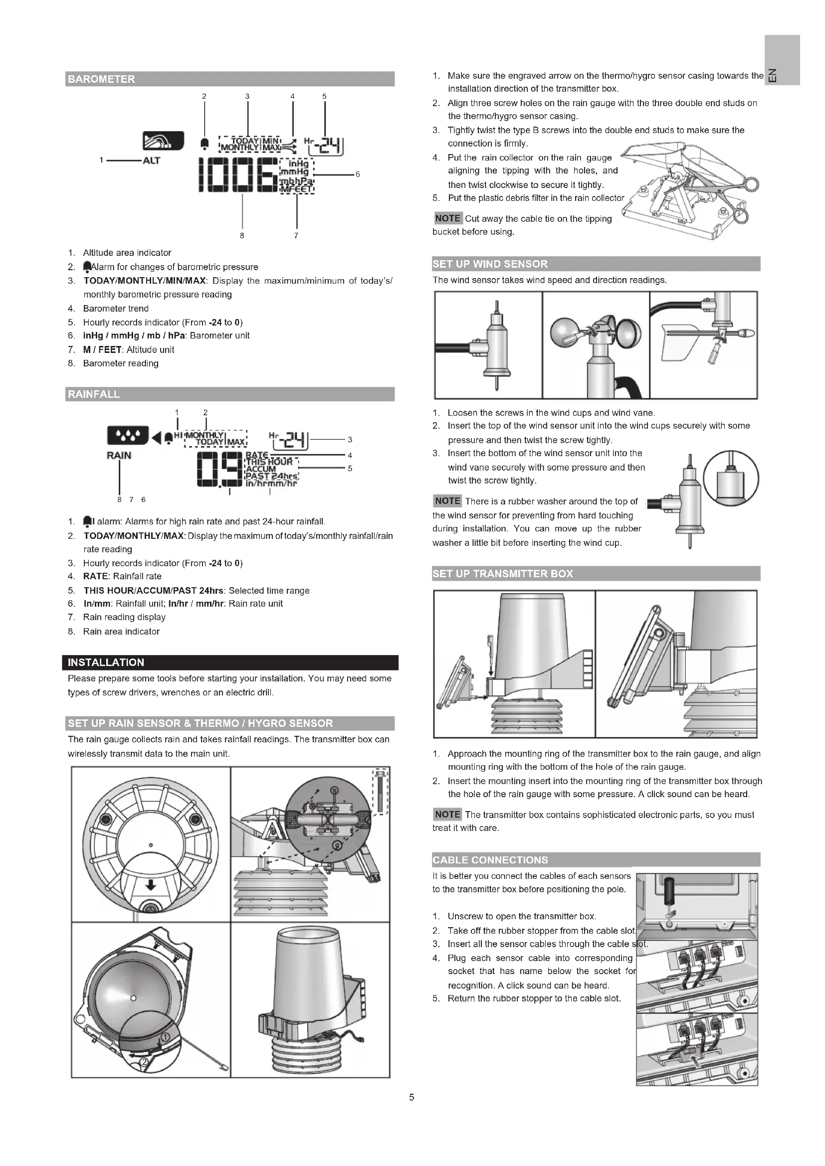
BAROMETER
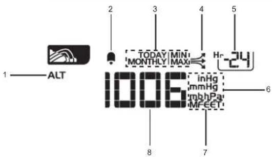
- Altitude area indicator
- Alarm for changes of barometric pressure
- TODAY/MONTHLY/MIN/MAX: Display the maximum/minimum of today's/ monthly barometric pressure reading
4.Barometer trend - Hourly records indicator (From -24 to 0)
- inHg / mmHg / mb / hPa: Barometer unit
- M/FEET: Altitude unit
- Barometer reading
RAINFALL
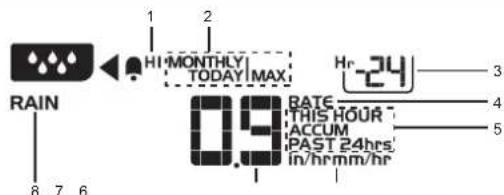
- alarm: Alarms for high rain rate and past 24-hour rainfall.
- TODAY/MONTHLY/MAX: Display the maximum of today's/monthly rainfall/rain rate reading
- Hourly records indicator (From -24 to 0)
- RATE: Rainfall rate
- THIS HOUR/ACCUM/PAST 24hrs: Selected time range
- In/mm: Rainfall unit; In/hr / mm/hr: Rain rate unit
- Rain reading display
- Rain area indicator
INSTALLATION
Please prepare some tools before starting your installation. You may need some types of screw drivers, wrenches or an electric drill.
SET UP RAIN SENSOR & THERMO / HYGRO SENSOR
The rain gauge collects rain and takes rainfall readings. The transmitter box can wirelessly transmit data to the main unit.
- Make sure the engraved arrow on the thermo/hygro sensor casing towards the installation direction of the transmitter box.
- Align three screw holes on the rain gauge with the three double end studs on the thermo/hygro sensor casing.
- Tightly twist the type B screws into the double end studs to make sure the connection is firmly.
- Put the rain collector on the rain gauge aligning the tipping with the holes, and then twist clockwise to secure it tightly.
- Put the plastic debris filter in the rain collector
NOTE Cut away the cable tie on the tipping bucket before using.
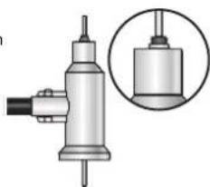
SET UP WIND SENSOR
The wind sensor takes wind speed and direction readings.
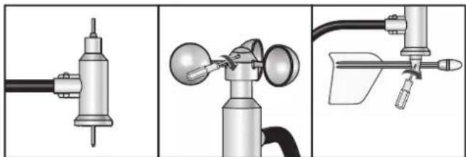
- Loosen the screws in the wind cups and wind vane.
- Insert the top of the wind sensor unit into the wind cups securely with some pressure and then twist the screw tightly.
- Insert the bottom of the wind sensor unit into the wind vane securely with some pressure and then twist the screw tightly.
NOTE There is a rubber washer around the top of the wind sensor for preventing from hard touching during installation. You can move up the rubber washer a little bit before inserting the wind cup.
SETUPTRANSMITTERBOX
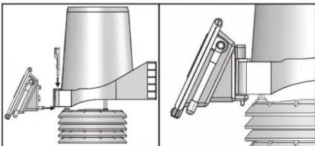
- Approach the mounting ring of the transmitter box to the rain gauge, and align mounting ring with the bottom of the hole of the rain gauge.
- Insert the mounting insert into the mounting ring of the transmitter box through the hole of the rain gauge with some pressure. A click sound can be heard.
NOTE The transmitter box contains sophisticated electronic parts, so you must treat it with care.
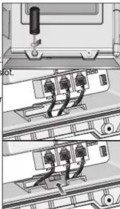
CABLE CONNECTIONS
It is better you connect the cables of each sensors to the transmitter box before positioning the pole.
- Unscrew to open the transmitter box.
- Take off the rubber stopper from the cable slot
- Insert all the sensor cables through the cable
- Plug each sensor cable into corresponding socket that has name below the socket for recognition. A click sound can be heard.
- Return the rubber stopper to the cable slot.
TRANSMITTER BOX-BATTERY INSTALLATION
The solar panel on transmitter box is an energy saving feature, which is an environmentally friendly way to provide power to the sensors and prolongs battery life. It can entirely provide power to the supplied rechargeable battery. Sensors can operate entirely on the rechargeable battery power. Locate the transmitter box under direct sunlight for power supplying by the solar panel.
The rechargeable battery from factory is not with full battery for long time use and it probably becomes low battery during the shipping. We recommend you to charge it for several hours by the connected solar panel.
You can also purchase a power adapter separately for directly providing power to the transmitter box. The output voltage of the power adapter is 3V. Route the adapter cable through the cable slot.
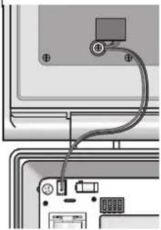
Please check the solar panel connection. If it is not firmly plugged, please re-connect the solar panel:
Plug the end of color-cored connector into corresponding socket in the transmitter box as shown below and place the wires neatly inside the box.
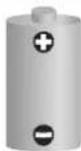
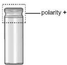
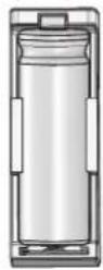
To install the rechargeable battery:
Insert the battery into the battery compartment, matching the polarity +1 .
CHANNEL SETTING
Your weather station system can expand with up to 8 sets of thermometer & humidity sensors, and one of each of wind and rain sensors, which share one main unit to display the weather readings. You can number each transmitter box with an independent channel ID (1-8) by sliding the switches.
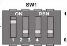
Please follow the below chart to adjust the sliding switches of SW1:
NOTE The below 0 in the chart represents off and 1 represents on.
| CH PIN 2 PIN 3 PIN 4 | ||
| Channel 1 0 0 0 | ||
| Channel 2 0 0 1 | ||
| Channel 3 0 1 0 | ||
| Channel 4 0 1 1 | ||
| Channel 5 1 0 0 | ||
| Channel 6 1 0 1 | ||
| Channel 7 1 1 0 | ||
| Channel 8 1 1 1 |
For obviously indicate the status of your channel, you can turn on the LED light in the corresponding transmitter box by sliding the PIN 1 switch to 1.
| Function PIN 1 | |
| Disable LED 0 | |
| Enable LED 1 |
After setting, please turn off the LED light by sliding the PIN 1 switch to 0 to save power, and then close the box by tightening the screws.
NOTE The flashing LED indicates a normal transmission (See LED Light Indicator).
REMOVE SETTING
For removing the previous setting from the transmitter box, you can press RESET and KEY at a time, then only release RESET, red light flashes 5 times. Then release KEY. The channel setting and calibrated wind direction are all removed from the transmitter box.
LED LIGHT INDICATOR
There are three colors of LED lights in transmitter box, green, red and blue. Different color combinations indicate different status.
| Light Color Operations | |
| Blue->green->red | Flash once when you (Press and )release RESET |
| Red flashes every second F | ash 5 times then remove setting of all the sensors from transmitter box (See Remove setting section) |
| Red | Wind direction calibration (See Direction Calibration). |
| Blue flashes | A normal transmission (WMR300A) |
| Green flashes | A normal transmission (WMR300) |
SENSORS INSTALLATION
You have three options to install the sensors.
The transmitter box is capable of transmitting data wirelessly an approximate operating range of 300m (1000 feet). Ideal placements for the sensor would be in any location on the roof of a building that is in an open area away from trees or other obstructions preventing from the wind flow for an accurate reading. Additionally, locate the transmitter box at the direct sunlight for power supplying by the solar panel.
| Solar panel facing: | If you reside in the: |
| North | Southern Hemisphere |
| South | Northern Hemisphere |
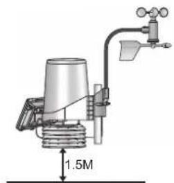
NOTE Make sure the temperature and humidity sensor should be located at least 1.5 meters above the ground surface to avoid the ground temperature affecting accuracy of the temperature and humidity sensor.
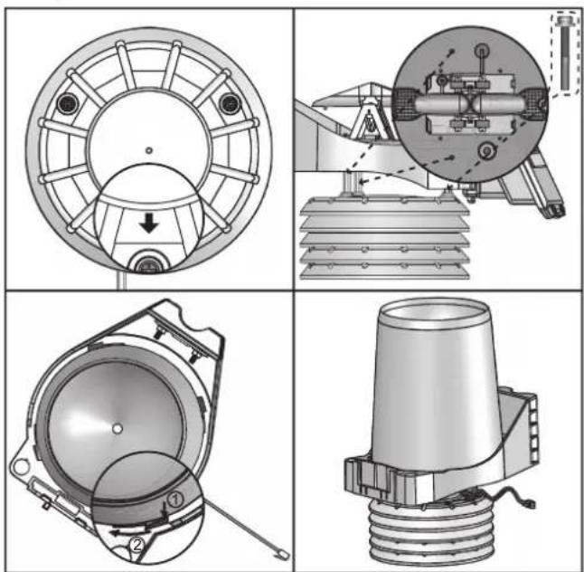
Option 1: All sensors are installed on a pole.
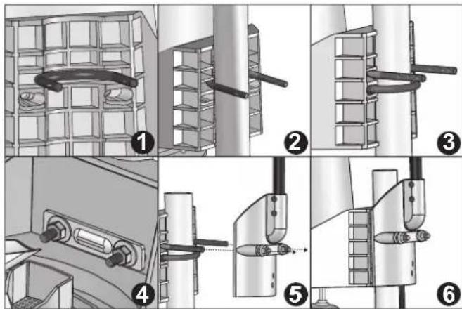
NOTE Please take off the rain collector before installation and choose a pole with the diameter that is about 32-45mm.
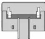
- Locate one U-bolt without flat washers, lock washers and hex nuts into the gap of the rain gauge (Figure 1).
- Let the pole fully approach to the inner of the U-bolt (Figure 2).
- Locate the other U-bolt without flat washers, lock washers and hex nuts into the screw holes of the rain gauge (Figure 3).
- Put the backing metal plate through the U-bolt and securely tighten two pairs of the flat washers, lock washers and hex nuts over the plate (Figure 4) by wrench.
- Insert the two ends of the first U-bolt into the screwholes of the wind sensor (Figure 5).
- Tighten the other two pairs of flat washers, lock washers and hex nuts on the U-bolt of the wind sensor by wrench (Figure 6).
NOTE Make sure the water bubble in the balance indicator on the rain gauge stay within the circle. Check the balance status regularly for an accurate rainfall rate reading.

- Follow the instructions in sections of Cable Connections, Transmitter Box-Battery Installation and Channel Setting.
- Securely locate the pole in your desired outdoor area.
- Route the excessive cables neatly by using the provided cable ties.
NOTE 6 meters wind sensor cable is provided for you to locate the wind sensor separately from the pole like in Option 2 and Option 3. Route the excessive cables if necessary.
NOTE Put the plastic debris filter into the rain collector. Please check the filter regularly and ensure it is not fully covered by the leaves or other objects.
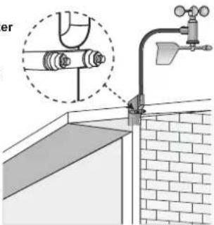
Option 2: Wind sensor Is Installed separately; other sensors with transmitter box are installed on a pole.
- Follow the steps 3-4 in Option 1 to install the temperature/hygro sensor and rain sensor on a pole.
- Insert the Type A screws into the wind sensor. Securely screw them into your desired location using wrench.
- Follow the steps 7-9 in Option 1 to complete the installation.
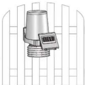
Option 3: Extingting wind sensor is installed on a pole; other sensors with transmitter box are installed separately.
- Follow the steps 5-6 in Option 1 to install the wind sensor on a pole.
- Insert the Type A screws into the rain gauge. Securely screw them into your desired location using wrench.
- Follow the steps 7-9 in Option 1 to complete the installation.
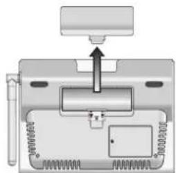
MAIN UNIT-BATTERIES INSTALLATION
To insert batteries:
- Remove the battery compartment cover.
- Insert the supplied batteries in the compartment, matching the polarities (+ / -) .
- Press RESET in the compartment.
- Close the battery compartment cover.
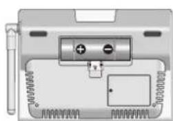
NOTE Do not use rechargeable batteries. It is recommended that you use alkaline batteries with this product for longer performance.
Low battery indicators:
| Icon Meaning | |
| MAIN | Main unit batteries low |
| SENSOR | Transmitter box(es) batteries low |
| Transmitter box(es) / main unit batteries low |
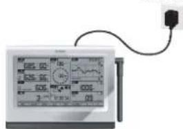
For continuous use, install the power adapter. The batteries are for back-up use only. Plug the power adapter into an electrical outlet not controlled by a wall switch.
NOTE The power adapter is intended to be correctly oriented in a vertical or floor mount position. The prongs are not designed to hold the plug in place if it is plugged into a ceiling, under-the-table or cabinet outlet.
Power Adapter
乙
PAIRING SENSORS / REMOVE SENSORS
To pair a sensor:
- The SW4 pairing switch in transmitter box is set to 1 (ON).
- Press TODAY area.
- Press and hold SET and atuntime until you enter sensor setup mode. (All sensor readings disappear on the screen - displays on the screen.)
- Press or to select the channel you want to add the sensor. The channel in dash mode ( SET displays) is available for pairing a sensor.
- Press and hold SET for 2 seconds. There is a beep. Press anywhere on the panel not in
- SEARCH indicator in CBAI shes to do pairing.
- When SEARCH disappears and the selected channel of sensor displays the weather reading on the screen, the pairing is complete and successful.
NOTE The main unit searches the sensor for about 10 minutes. Please complete the pairing within an hour after you switch on the pairing switch in the transmitter box. Otherwise, you need to turn off the pairing switch, and then switch it on again.
NOTE Make sure you calibrate the direction of wind vane on the wind sensor after adding sensors, see Direction Calibration for details.
TIP The transmission range may vary depending on many factors. You may need to experiment with various locations to get the best results. Make the antenna of the transmitter box and the one on the main unit be paralleled to get a better pairing performance.
To remove a sensor:
- Press TODAY area.
- Press and hold SET and a until you enter sensor setup mode. (The weather reading disappears on the screen, -- displays on the screen).
- Press or to select the channel of the sensor you want to remove. You can only remove the sensor that the reading is not in dash mode (dMMS).
- Press and hold MEM for at least 2 seconds. There is a beep and then the screen shows --, the sensor is successfully removed from the main unit.
CLOCK
MANUALLY SET CLOCK
NOTE To set the clock/calendar manually, disable the clock signal reception first (see To Enable / Disable signal reception).
To manually set the clock / calendar:
- Press TODAY area to activate displays next to the area and the tool bar displays at the below of the screen.
- Press and hold SET on the tool bar, then toggle SET between time zone offset, day time saving options, 12/24 hr format, hour, minute, year, day/month format, month, day, weekday, language, latitude and longitude.
- Once in desired setting, press or to change the settings.
- Press:
to continue and continue to next setting
OR
- Touch panel area (except tool bar) to confirm and exit.
NOTE For WMR 300, the range of time zone offset is between -12 and +12. You should manually input the time zone of your location, please check your local weather observatory for detail. For example, Hong Kong should be set to +8.
NOTE The language options are English (E), Russian (R), Spanish (S), Italian (I), German (D) and French (F).
NOTE You need to input latitude and longitude of your location. Please refer to your local weather observatory website. The latitude and longitude input affects the sunrise/sunset time.
NOTE Excepting the latitude and longitude, AUTO/DST (Daylight saving time)/ST (Standard time) settings also affect the sunrise/sunset time. If AUTO is set, the sunrise/sunset time follows the DST/ST setting of the RF clock data. If ST is set, the sunrise/sunset time assumes standard time. If DST is set, the sunrise/sunset time assumes daylight saving time.
To select clock display mode:
Press TOPOY repeatedly to toggle among:
Clock with seconds
- Clock with weekday
- Date with year
CLOCK RECEPTION
This product is designed to synchronize its clock automatically with a clock signal.
WMR300:
Slide switch to EU / UK to select the desired signal and manually set clock by selecting time zone between -12 and +12.
EU: DCF-77 signal: within 1500km (932 miles) of Frankfurt, Germany.
UK: MSF-60 signal: within 1500km (932 miles) of Anthorn, England.
NOTE Press RESET whenever you change EU / UK setting.
WMR300A:
- WWVB-60 signal: within 3200km (2000 miles) of Fort Collins Colorado. Manually set clock to select time zone Pacific (P)/Mountain (M)/Central (C)/Eastern (E).
The icons below indicate the status of the clock reception signal.
| Icon Meaning | |
| Time is synchronized, but not updated once during the last 48 hours | |
| Flashing | Receiving signal is weak. |
| Time is synchronized and updated at least once during the last 48 hours. | |
| Flashing | Receiving signal is strong |
NOTE Reception lakes 4-10 minutes for synchronizing.
To enable / disable signal reception:
Press and hold a place within TODAY area to enable / disable signal reception. A beep will sound to confirm action.
ALARM CLOCK
To set the daily alarm:
- Press TODAY area to activate. displays next to the area and the tool bar displays at the below of the screen.
ALARM 2. Press Press to turn on the daily alarm. and displays
Press to AARMF the daily alarm. disappears - Press UNIT to change the time display between 12hr/24hr format.
- Press and hold ALARM to enter editing mode.
- Press or to eit and press to confirm
- Press anywhere not in TODAY area to exit.
MOON PHASE
In the Northern hemisphere, the moon waxes (amount of moon we see that grows after the New moon) from the right. So, the sunlit part of the moon moves from right to left in the Northern hemisphere while in the Southern hemisphere, it moves from left to right. The direction depends on the latitude of the person observing it.
Below are two tables which diagrammatically illustrate how the moon will appear on the main unit.
Northern hemisphere
| New Moon Full Moon | ○ | ||
| Waxing Crescent | ○ | Waning Gibbous | |
| First quarter | ○ | Third quarter | |
| ○ | Waxing Gibbous | ○ | Waning Crescent |
Southern hemisphere
| New Moon Full Moon | ○ | ||
| Waxing Crescent | ○ | Waning Gibbous | |
| First quarter | ○ | Third quarter | |
| Waxing Gibbous | ○ | Waning Crescent |
To view moon phase:
- Press TODAY clock area to activate.
- Press or to view moon phase for specific dates.
WEATHER FORECAST
This product forecasts the next 12 to 24 hours of weather within a 30 - 50km (19-31 mile) radius (US - with a 75% accuracy).
| Icon | Meaning |
| Sunny | |
| Partly cloudy | |
| Cloudy | |
| Rainy | |
| Snowy |
TEMPERATURE AND HUMIDITY
To view temperature area:
Press INDOOR / OUTDOOR temperature area. displays on top of the temperature reading.
To change channel (outdoor temperature only):
Press to change channel.
To select the temperature measurement unit:
- Press to select ^ C / ^ F
NOTE The unit of all temperature related displays will be changed simultaneously.
To view humidity readings:
Press INDOOR/OUTDOOR humidity area. displays on top of the humidity reading.
To view temperature and humidity trend:
The temperature and humidity trend icons are based on recent sensor readings.
The trend lines are shown next to the temperature and humidity readings. The trend is shown as follows:
| Rising | Steady | Falling |
| → | → | → |
DEWPOINT/HEATINDEX/WINDCHILL
To view dew point:
Press 1 + heatedly until DEWPOINT displays.
To view heat index:
Press area repeatedly until HEAT INDEX displays.
| Temperature Range | Warning | Meaning |
| 27°C to 32°C(80°F to 89°F) | Caution | Possibility of heat exhaustion |
| 32°C to 40°C(90°F to 104°F) | ExtremeCaution | Possibility of heat dehydration |
| 41°C to 54°C(105°F to 129°F) | Danger | Heat exhaustion likely |
| 54°C to 92°C(130°F to 151°F) | Extreme danger | Strong risk of dehydration /sun stroke |
NOTE Heat index is only calculated when temperature is 80^ / 27^ or above.
To view wind chill:
- Press a buttonedly until WIND CHILL displays.
SUNRISE/SUNSET
NOTE Make sure you input latitude and longitude of your location TOBAY which affects the sunrise/sunset time.
NOTE Extingting the latitude and longitude, daylight saving time setting also affects sunrise and sunset (See Manually Set Clock).
You can view the sunrise or sunset time in
Press SUNRISE/SUNSET area displays on the top of the time display.
Press to bingge the time display between 12hr/24hr format.
WIND
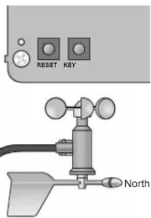
DIRECTION CALIBRATION
Before pairing a wind sensor, make sure the head of the wind vane of that sensor point to the north while pressing KEY for 2 seconds in the transmitter box to calibrate the direction. If the calibration is successful, red light flashes once. You can use a compass to look for an accurate direction of north if necessary.
However, if you are the user in North America, there are already 15^ (degree) variations existing between the true north and a compass reading of north. You can consult your local observatory about this issue.
If it is difficult to control the wind vane after installation, you can calibrate through setting on main unit.
- Make a compass approach to the wind vane.
- Calculate the angle between the current direction and the north direction.
- Press wind area to activate.
- Press and hold SET, and then press or to calibrate the angle value.
- Press SET again to confirm setting.
For example, inputting the angle value that you want to set as north. If current direction is 25 degree and you want to set it as north, then you input 25 degree in the calibration mode. Once you return to the idol mode, the direction reading displays 0 degree, which is the north.
NOTE You need to calibrate the wind sensor again if you want to relocate the sensor.
WIND SPEED / DIRECTION
To select wind display mode:
Press eea to toggle between:
GUST (Gust)
AVG(Average)
To select wind speed unit:
Press to switch among:
- Knots (knots)
- Kilometres per hour (km/h)
Miles per hour (mph) - Metres per seconds (m/s)
The wind level is shown by a series of text icons:
| LIGHT MODERATE STRONG STDRM | |||
| 2-8 mph(3-13 km/h) | 9-25 mph(14-41 km/h) | 26-54 mph(42-87 km/h) | >55 mph(>88 km/h) |
To read the wind direction:
| Status | Wind Direction Indicator | Meaning |
| GUST | ▲ | Real-time wind direction |
| AVG | ▲ | Real-time average wind direction |
| AVG | > (Max 6 sets) | Wind direction of last 1 hour |
NOTE The wind chill factor is based on the combined effects of temperature and wind speed. Displayed wind chill is calculated solely from channel 1 thermometer and humidity sensor.
BAROMETRIC PRESSURE
The altitude reflects distance from sea level at your position.
To set the altitude level compensation for the barometric readings:
- Press area to activate. displays next to the area and the tool bar displays at the below of the screen.
- Press the area until ALT displays on the screen. You are in altitude mode.
- Press and hold SET on the tool bar.
- Press or to edit. You can press to change UNIT altitude unit between M (Meter) and FEET (Feet) while editing.
- Press SET to confirm or touch panel area (except tool bar/barometer area) to confirm.
- After setting altitude, the new altitude setting will not be effective immediately. The ALT icon flashes and stops flashing until the next pressure sampling. The new altitude setting takes effect on the new pressure sampling.
NOTE When altitude is set to 0 meter, the pressure reading is the local pressure. If the altitude is set to the current location, the new pressure reading is an offset pressure to the sea level.
To select the measurement unit for the barometer:
- Press barometer area to toggle between altitude and current barometer.
- Press UNIT to select inHg (inches of mercury) / mmHg (millimetres of mercury) / mb (millibars per hectopascal) / hPa.
To view pressure trend:
The barometric pressure trend icons are based on recent sensor readings.
The trend lines are shown next to the pressure readings. The trend is shown as follows:
| Rising | Steady | Falling |
| → | → | → |
RAINFALL
To select rainfall display mode:
Press to toggle between:
THIS HOUR (Hourly rainfall)
RATE (Rain rate)
ACCUM (Accumulated rainfall)
PAST 24 hrs (Rainfall recorded in the past 24 hours)
To select the measurement unit for the rainfall:
Press to select between mm (millimeter) and in (inch).
To select the measurement unit for the rainfall rate:
Press UNIT to select between in/hr (inch per hour) and mm/hr (millimeter per hour).
ACCUMULATED RAINFALL
To display accumulated rainfall:
Press rain area repeatedly until ACCUM display. (SINCE displays in the TODAY clock area that displays the start date / time of rainfall recording simultaneously).
To reset SINCE time:
Press and hold MEM to set current time as start of accumulated rainfall records. The rainfall record is cleared and reset to 0.
BAR CHART
The bar chart simultaneously displays the data while you press on the corresponding area.
To select chart display mode:
Press on the below areas to toggle among these chart displays.
- IN TEMP (Indoor temperature)
IN HUM (Indoor humidity)
OUT TEMP (Outdoor temperature)
OUT HUM (Outdoor humidity) - DEWPOINT (Dew point)
- HEAT INDEX (Heat index)
WIND CHILL (Wind chill)
WIND (Wind speed)
- BARO (Barometer)
- RAINFALL (Rain)
To select time range display mode:
Press art area to toggle the chart records between the following time ranges.
LAST 24 HRS (Past 24 hours)
LAST 24 DAYS (Past 24 days)
LAST 24 MTHS (Past 24 months)
To select record range display mode:
Press bar chart area, and then press the chart records between the following ranges.
MAX (Maximum record)
MIN (Minimum record)
NOTE The purpose of the bar chart is to provide a quick comparison between
the records. Changing the measurement unit will have corresponding effect on the bar chart display.
MEMORY
MAX / MIN OF TODAY/MONTHLY RECORDS
| Area Type | of Memory Indicators | ||
| Temperature | Current indoor / outdoor temperature | MONTHLY | MAX |
| MIN | |||
| TODAY | MAX | ||
| MIN | |||
| Heat index | MONTHLY | MAX | |
| TODAY | |||
| Wind chill | MONTHLY | MIN | |
| TODAY | |||
| Dewpoint | MONTHLY | MAX | |
| TODAY | MIN | ||
| Humidity | Current indoor / outdoor humidity | MONTHLY | MAX |
| MIN | |||
| TODAY | MAX | ||
| MIN | |||
| Wind Gust | wind speed | MONTHLY | MAX |
| TODAY | |||
| Barometer Barometer | Barometer | MONTHLY | MAX |
| MIN | |||
| TODAY | MAX | ||
| MIN | |||
| Rain | Rain rate | MONTHLY | MAX |
| TODAY | |||
| Rainfall | MONTHLY | MAX | |
| TODAY | |||
To view memory records:
- Press desired area to activate.
- Press MEM to toggle between MIN/MAX of TODAY/MONTHLY recorded readings.
To clear individual area records:
- Select a record in memory.
- Press and hold MEM for 2 seconds.
- Delete process is complete when display changes to current reading.
NOTE When MAX/MIN reading displays, the corresponding timestamp will be displayed in the TODAY area
HOURLY RECORDS
| Display | Hourly readings of up to |
| Barometer | 24 hours back |
| Hourly Rainfall | 24 hours back |
To view hourly records:
-
Press desired area to activate until the hour frame displays.
-
Press or to view current (0 hr) / hourly reading (from -1hr to -24hr).
DATALOG
The weather data can be automatically saved by setting data logger, and then you can view the data through a PC program by uploading to the PC.
To set data log:
- Press TODAY area, then press MEM to activate DATA LOG mode.
- Press and hold SET
- Press or to select frequency of data recording (1/5/15 /60 minutes).
- Press SET
- Number of days memory will allow for records will be displayed.
| Frequency In Minutes | No. of Days Available for Data Logging with Memory Available |
| 1 | 22D (3 weeks) |
| 5 | 113D (3.5 months) |
| 15 | 341D (10.5 months) |
| 60 | 1364D (3.5 years) |
To view remaining days for records:
Press MEM area.
NOTE When DATA LOG is almost full, DATA LOG flashes to remind you to transfer the data to PC for storage. Otherwise, data logger cannot log any more data when it is full.
To upload records to PC:
Plug the small end of the USB cable to USB port on the main unit and the big end of the cable into the USB port of the PC. The records will be uploaded onto the software run by the PC via the USB cable.
displays in TODAY area on main unit.
NOTE PC program provided must be installed before uploading of records from main unit.
To clear records:
- Press TODAY area, then press MEM DATA LOG displays.
- Press and hold MEM
- After all the data cleared, the display shows the new time remaining. Delete process is complete and successful.
ALARM
Weather alarms are used to alert you of certain weather conditions. Once activated, the alarm will turn on and start flashing when a certain criterion is met. The alarm does not flash and goes back to normal until the reading is not beyond the alarm setting anymore.
| Area | Type of Alarm | |
| Clock | Daily alarm | |
| Temperature | Current indoor / outdoor temperature | HI |
| LO | ||
| Heat index | HI | |
| Dew point | HI | |
| LO | ||
| Wind chill | LO | |
| Humidity Current indoor / outdoor humidity | HI | |
| LO | ||
| Wind | Gust wind speed | HI |
| Barometer | Barometric pressure | * |
| Rain | Rain rate | HI |
| Past 24-hour rainfall | HI | |
*Barometric pressure alarm is a pressure drop alarm
To set the alarm:
- Press desired area to activate.
- Toggle ALARM to display current reading and HI / alarm.
- Press and hold ALARM
- Press or to set the desired values.
- Press
ALARM to confirm and continue to next setting
OR
- Touch anywhere on the screen (except tool bar / confirm and exit.
To enable / disable alarms:
- Press desired area to activate.
- Press 10 ARM May set HI / LO alarm
- Press ARM's alarm on or off.
NOTE -- indicates alarm is not set / disabled.
NOTE Clock alarm sound is different from weather alarms to allow for easy differentiation by user.
To silence any alarm:
- Press anywhere on the touch panel.
OR
The alarm automatically turns off after 2 minutes.
NOTE When alarm is on, the channel of triggered alarm will be flashed and alarm sound lasts for 2 minutes.
BACKLIGHT
Press anywhere on the touch panel to activate the backlight for 8 seconds.
OR
If the main unit is powered by power adapter, switch the LIGHT to ON in the main unit compartment. The light will be on until you switch it OFF.
NOTE You need to take off the battery compartment cover to do switching.
RESET
Main unit:
Press RESET to return to the default settings.
NOTE You need to take off the battery compartment cover to do switching.
Transmitter box:
Press RESET to remove the record of the calibrated wind direction.
MAINTAINANCE
Each sensor of this kit has a durable plastic casing that should retain its luster for many years. It is better to do regular maintenance to keep the sensors with high accuracy every half year. Do cleaning the casing only with a soft cloth slightly dampened with water or a mild soap. Please use screw drivers or wrench to take some parts off if necessary.
Electrical storms can sometimes cause power surges harmful to electronic equipment. For your own safety, take caution when using the main unit or doing maintenance during storms.
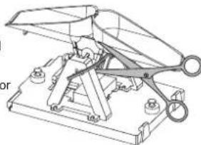
TO MAINTAIN THE THERMO/HYGRO SENSOR
- Remove the rain collector from the rain gauge.
- Unscrew the three type B screws from the rain gauge
- Unscrew the three screws from the bottom of the thermo/hygro sensor casing.
- Clean the casing excluding the one with sensor by water, and then remove the dust around the sensor carefully.
- Install all the parts until they are entirely dried.
NOTE If the temperature and humidity readings are
still strange and inaccurate, you need to consider replacing this sensor, please contacting our customer service for the details.
乙
TROUBLESHOOTING
| Problem Symptom Remedy | ||
| Barometer Strange readings Check altitude setting on the main unit. | ||
| Wind sensor | No updates of the wind direction | Check the wind vane. |
| Display dashes on main unit | 1. Check the connections. 2. Check the channel setting. 3. Check the pairing successful or not. | |
| Rain sensor | No readings | 1. Check the cable tie on the lipping bucket to be cut away or not. 2. Check the balance indicator. 3. Check the plastic filler in rain collector. 4. Check the connections. |
| Strange readings | 1. Check theplasticfillerintheraincollector. 2. Check the balance indicator. | |
| Tem p/h ygr o sensor | Display dashes | 1. Check the connections. 2. Check the pairing. 3. Check the channel setting. |
| No outdoor temp/ hygro readings | 1. Check the rechargeable battery in transmitter box. 2. Check the power adapter connection and main unit batteries status. 3. Do maintenance for the sensor. | |
| Calendar | Strange date / month | 1. Change language. 2. Check the calendar setting. |
| Clock | Cannot adjust clock | Disable radio-controlled clock. |
| Cannot auto-synchronize | 1. Check batteries status. 2. Reset the main unit. 3. Manually activate radio controlled clock. | |
| Sunrise/Sunset | Strange readings | 1. Set longitude/latitude. 2. Check the daylight saving time setting. |
| Transmitter box | LED light(s) do not flash | 1. Check the switch. 2. Check the polarity of the rechargeable battery. 3. Check the connection of the solar panel. |
| Sensors pairing | Time is too long | 1. Adjust the antennas to be parallel. 2. Reset the pairing switch (switch off then on again). |
PRECAUTIONS
- Do not subject the unit to excessive force, shock, dust, temperature or humidity
- Don't cover the ventilation holes with any items such as newspapers, curtains etc.
- Do not immerse the unit in water. If you spill liquid over it, dry it immediately with a soft, lint-free cloth.
- Do not clean the unit with abrasive or corrosive materials.
- Do not tamper with the unit's internal components. This invalidates the warranty.
- Only use fresh batteries. Do not mix new and old batteries.
Images shown in this manual may differ from the actual display. - When disposing of this product, ensure it is collected separately for special treatment.
- Placement of this product on certain types of wood may result in damage to its finish for which Oregon Scientific will not be responsible. Consult the furniture manufacturer's care instructions for information.
The contents of this manual may not be reproduced without the permission of the manufacturer. - Do not dispose old batteries as unsorted municipal waste. Collection of such waste separately for special treatment is necessary.
- Please note that some units are equipped with a battery safety strip. Remove the strip from the battery compartment before first use.
NOTE The technical specifications for this product and the contents of the user manual are subject to change without notice.
SPECIFICATIONS
MAIN UNIT
| Dimensions (L x W x H) | 205 x 146 x 52.5 mm (8.07 x 5.75 x 2.07 inches) |
| Weight 740g (1.63lbs) with batteries; 540 g (1.2lbs) without battery | |
| Battery 3 x C size 1.5V batteries | |
| Adaptor DC 6V 100 mA adaptor | |
| Support channels 1 wind, 1rain, 1UV, 1solar and 1~8 thermo/hygro | |
INDOOR BAROMETER
| Barometer unit Mb | hPa, inHg and mmHg |
| Measuring range 5-10 to 1,100mb/hPa | |
| Accuracy +/- 1mb/hPa between 677 & 1,016hPa | |
| Resolution | 0.1mb/hPa ,0.01inHg ,0.1mmHg (remark: inHg and mmHg converted from the pressure of 0.1mb resolution) |
| Altitude setting | -600m ~ 4570m (-999feet ~ 14993 feet)User setting for offset local pressure to sea level pressure |
| Weather forecast Sunny, Snowy, Partly Cloudy, Cloudy and Rainy | |
| Display modes Current, Max, Min, Historical data for last 24hrs | |
| Memory modes Today Max & Min, Monthly Max & Min (with time stamp) | |
| Alarm Pressure change alarm | |
INDOOR TEMPERATURE
| Temp. unit °C or °F | |
| Displayed range 0°C to 60°C | |
| Operating range 0°C to 60°C | |
| Accuracy +/- 0.5°C or 1°F typical at room temperature | |
| Resolution 0.1°C or 0.1°F (remark: °F convert from 0.1°C display) | |
| Display modes | Current, Min and Max |
| Memory modes | Today Max & Min, Monthly Max & Min (with time stamp) |
| Alarm | Hi / Lo |
INDOOR RELATIVE HUMIDITY
| Displayed range 0% to 99%RH | |
| Operating range 0% to 99%RH | |
| Resolution 1% | |
| Accuracy +/-3% (Typical) @ 25°C | |
| Display modes | Current, Min and Max |
| Memory modes | Today Max & Min, Monthly Max & Min (with time stamp) |
| Alarm | Hi / Lo |
RADIO-CONTROLLED/ATOMIC CLOCK
| Synchronization | Auto or disabled |
| Clock display | HH:MM:SS / HH:MM Weekday |
| Hour format | 12hr AM/PM or 24hr |
| Calendar | DD/MM/YR or MM/DD/YR |
| Weekday in 6 languages | EN, FR, DE, IT, ES, RU |
OUTDOOR TEMPERATURE/HUMIDITY UNIT RELATIVE TEMPERATURE
| Dimensions (Ø x H) | Ø190 x 126 mm (Ø7.48 x 4.96 inches) |
| Weight | 580g(1.28lbs) |
| Temp. unit | °C or °F |
| Displayed range -40 | C to 65°C |
| Operating range -40 | C to 65°C |
| storage temperature | -45°C to 70°C |
| Resolution 0.1°C | |
| Accuracy | +/- 0.5 °C |
| Memory modes | Today Max & Min, Monthly Max & Min (with time stamp) Dew point temp. Max and Min Wind chill temp. Min Heat index temp. Max |
| Alarm | Hi / Lo for current temp and dew point Hi for heat index Lo for wind chill |
RELATIVE HUMIDITY
| Displayed range | 0% to 99%RH |
| Operating range | 0% to 99%RH |
| Resolution | 1% |
| Accuracy | 3% |
| Display modes | Current, Min and Max |
| Memory modes | Today Max&Min, Monthly Max & Min (with time stamp) |
| Alarm | Hi / Lo |
SOLAR RF TRANSMITTER BOX
| Dimensions (L x W x H) | 178 x 154 x 91.7mm (7 x 6.06 x 3.61 inches) |
| Weight | 530 g (1.2 lbs) |
| Battery | 1.2 V recharged battery |
| RF frequency | 915Mhz (US) / 868Mhz (EU, UK) |
| Range | 300 meters (1000 feet), line of sight no obstructions |
| Transmission intervals | Wind: 2.5~3 sec TH: 10~12 sec Rain: 20~24 sec |
| Channel | 1wind, 1rain, 1UV, 1solar and 1thermo/hygro |
RAIN GAUGE
| Dimensions (L x W x H) | 287.5 x 226 x 279 mm (11.32 x 8.90 x 10 inches) |
| Weight | 1213g (2.674lbs) |
| Operating temperature | -40 ~ +65°C |
| Storage temperature | -45 ~ + 70°C |
| Unit for rainfall | mm and in |
| Unit for rain rate | mm/hr and in/hr |
| Range for rainfall | 0~199.99inches |
| Range for rain rate | 0~1016mm/hr (0~393.6 inches) |
| Resolution | 0.01inches (0.254mm) typical |
| Accuracy for rainfall | +/- 4% |
| Accuracy for rain rate | ±5% 0~ 127mm/Hr (0~5 in/hr) |
| Memory modes | Acc rainfall for last memory reset Max rain rate |
| Display modes | Rain rate, Rainfall (Past 24hrs/Hourly/Accumulated) |
| Alarm | Hi for rain rate & past 24 hr |
WIND SENSOR UNIT
| Dimensions (L x W x H) | 516 x 345.5 x 135 mm (20.31 x 13.60 x 5.32 inches) |
| Weight | 520g (1.15lbs) |
| Operating temperature | -40 ~ +65°C |
| Storage temperature | -45 ~ + 70°C |
| Wind speed unit | m/s, km/h, mph, knots |
| Wind speed range | 0~80m/s |
| Wind speed resolution 0.1 | mph or 0.1knot or 0.1m/s |
| Speed accuracy | +/- 0.9m/s (under 18m/s) +/- 5% (above 18m/s) |
| Direction resolution | 1° |
| Direction resolution | 3° |
| Memory modes | Today/Monthly Max gust speed with direction (with lime stamp) |
| Display modes | Gust/average wind speed & direction |
| Alarm | Hi for Gust speed |
ABOUT OREGON SCIENTIFIC
Visit our website (www.oregonscientific.com) to learn more about Oregon Scientific products.
For any enquiry, please contact our Customer Services at info@oregonscientific.com.
EU-DECLARATION OF CONFORMITY
Hereby, Oregon Scientific, declares that this Ultra-precision Professional Weather System (model: WMR300 / WMR300A) is in compliance with the essential requirements and other relevant provisions of Directive 1999/5/EC. A copy of the signed and dated Declaration of Conformity is available on request via our Oregon Scientific Customer Service.


COUNTRIES RTTE APPROVED COMPLIED
All EU countries, Switzerland and Norway
FCC STATEMENT
This device complies with Part 15 of the FCC Rules. Operation is subject to the following two conditions: (1) This device may not cause harmful interference, and (2) This device must accept any interference received, including interference that may cause undesired operation.
WARNING Changes or modifications not expressly approved by the party responsible for compliance could void the user's authority to operate the equipment.
NOTE This equipment has been tested and found to comply with the limits for a Class B digital device, pursuant to Part 15 of the FCC Rules. These limits are designed to provide reasonable protection against harmful interference in a residential installation.
This equipment generates, uses and can radiate radio frequency energy and, if not installed and used in accordance with the instructions, may cause harmful interference to radio communications. However, there is no guarantee that interference will not occur in a particular installation. If this equipment does cause harmful interference to radio or television reception, which can be determined by turning the equipment off and on, the user is encouraged to try to correct the interference by one or more of the following measures:
Reorient or relocate the receiving antenna.
Increase the separation between the equipment and receiver.
Connect the equipment into an outlet on a circuit different from that to which the receiver is connected.
Consult the dealer or an experienced radio / TV technician for help.
DECLARATION OF CONFORMITY
The following information is not to be used as contact for support or sales. Please call our customer service number (listed on our website at www.oregonscientific.com), or on the warranty card for this product for all inquiries instead.
We
Name: Oregon Scientific, Inc.
Address: 19861 SW 95th Ave.Tualatin, Oregon 97062 USA
Telephone No.: 1-800-853-8883
declare that the product
Product No.
Product Name: Ultra-precision Professional Weather System
Manufacturer:
Address:
WMR300/WMR300A
Ultra-precision Professional Weather System
IDT Technology Limited
Block C, 9/F, Kaiser Estate,
Phase 1, 41 Man Yue St.,
Hung Hom, Kowloon,
Hong Kong
is in conformity with Part 15 of the FCC Rules. Operation is subject to the following two conditions: 1) This device may not cause harmful interference. 2) This device must accept any interference received, including interference that may cause undesired operation.
Uber Oregon Scientific 14

1 x Pile rechargeable
AA 1.2V
PLUVIOMETRE
INDICATORI A LUCE LED
ACCESSORIES - SENSOREN
NEERSLAGSENSOR/THERMO-/HYGROSENSOREN OPSTELLEN
Para colocar as pilhas:
EMPARELHAR SENSORES/REMOVER SENSORES
Para repor as horas SINCE (DeSde):
KLOCKA/ALARM/VADERPROGNOS/MANFAS
NOTERA Mottageningen tar 4-10 minutes for synchronising.
Aktivera / inaktivera signalmottaginatingen:
Oregon Scientific Inc.
Tualatin, Oregon USA
欧西亚中国授权制造商
展科电子(深圳)有限公司
制造地:中国深圳宝安臣田工业村

超精密專業氣象系統
機型:WMR300/WMR300A
用户手册
目錄
简介 1
套件内容 1