
HCA62320BH - Basket BEKO - Free user manual and instructions
Find the device manual for free HCA62320BH BEKO in PDF.
| Product type | Wall-mounted cooker hood |
| Brand | Beko |
| Model | HCA62320BH |
| Dimensions (W x D x H) | 596 x 374 x 310-550 mm (adjustable) |
| Power supply | 220-240 V ~ 50/60 Hz |
| Maximum power | Not explicitly specified, estimated 200 W |
| Operating modes | Extractor (external ducting) or recirculator (recycling with charcoal filter) |
| Available speeds | 3 speeds (1, 2, 3) + stop (0) |
| Lighting | Replaceable halogen/LED bulb(s) |
| Control type | Mechanical (push buttons) |
| Exhaust connection diameter | 120 or 150 mm |
| Minimum distance between hood and hob | 45 cm (electric) / 55 cm (gas) |
| Grease filter | Aluminium, washable (hand or dishwasher) every 35 hours |
| Charcoal filter | Optional, to be replaced every 6 months |
| Noise level | Not specified |
| Net weight | Not specified, estimated 10-15 kg |
| Expected lifespan | 10 years |
| Standards and certifications | CE, WEEE, RoHS |
| Included accessories | Grease filter, wall plugs and fixing screws |
| Warranty | Standard manufacturer warranty (see warranty card) |
Frequently Asked Questions - HCA62320BH BEKO
User questions about HCA62320BH BEKO
0 question about this device. Answer the ones you know or ask your own.
Ask a new question about this device
Download the instructions for your Basket in PDF format for free! Find your manual HCA62320BH - BEKO and take your electronic device back in hand. On this page are published all the documents necessary for the use of your device. HCA62320BH by BEKO.
USER MANUAL HCA62320BH BEKO
natural_image
Simple line drawing of a kitchen range hood with three circular buttons (no text or symbols)HCA62320W
HCA62320B
HCA62320WH
HCA62320BH
EN PL RO DE ES FR
NL CS SL SK UA
01M-8851163200-4117-02

Please read this manual first!
Dear Customers!
Thank you for preferring a Beko product. We hope that you get the best results from your product which has been manufactured with high quality and state-of-the-art technology. Therefore, please read this entire user manual and all other accompanying documents carefully before using the product and keep it as a reference for future use. If you handover the product to someone else, give the user manual as well. Follow all warnings and information in the user manual.
Remember that this user manual is also applicable for several other models. Differences between the models are explicitly described in the manual.
Meanings of the Symbols
Following symbols are used in the various section of this manual:

Important information and useful hints about usage.

WARNING: Warnings for dangerous situations concerning the safety of life and property.
Warning for electric shock.
Warning for hot surfaces.

This product has been manufactured in environmental friendly modern plants without giving any harm to the nature.
CONTENTS
| ENGLISH | 04-20 |
| POLSKI | 21-37 |
| ROMÂNĂ | 38-54 |
| DEUTSCH | 55-74 |
| ESPAŇOL | 75-94 |
| FRANÇAIS | 95-112 |
| NEDERLANDS | 113-131 |
| ČESKY | 132-149 |
| SLOVENŠČINA | 150-167 |
| SLOVENSKÝ | 168-185 |
| УКРАЇНСЬКИЙ 186-208 | |
1
Important safety and environmental instructions
This section contains safety instructions that will help protect from risk of personal injury or property damage. Failure to follow these instructions invalidates the granted warranty.
1.1 General safety
• Always have the installation and repairing procedures carried out by the Authorized Service Agent. Manufacturing firm shall not be held responsible for damages that may be caused by unauthorized persons.
- This appliance is not intended for use by persons (including children) with reduced physical, sensory or mental capabilities, or lack of experience and knowledge. Children should be supervised to ensure that they do not play with the appliance.
1.1.1 Electrical safety
• Always unplug the appliance from the mains supply during installation, maintenance, cleaning and repair operations.
- If the power cable is faulty, it should be replaced by a qualified person certified by the manufacturer, after-sales service or similar (preferably an electrician) or a person described by the importer.
- Operating voltage is 220 to 240 volts.
- If the appliance has a failure, it should not be operated unless it is repaired by the Authorized Service Agent. There is the risk of electric shock!
- Do not route power cable close to hobs. Otherwise power cable may cause fire since it melts down easily.
- Never plug the hood before installation is completed.
- In order to obtain the best performance, external conductor must not be longer than 4 m. It must not contain more than 2 perpendicular (90°) angles and its diameter must be min. ∅120 mm.
- Disconnect the appliance from mains before any intervention to the internal parts of the appliance.
- Use the appliance with a grounded outlet only.
1
Important safety and environmental instructions
1.1.2 Product safety
- You can use a pipe with a diameter of 120 mm or 150 mm on the flue connection of the hood.
- Do not make connections to the flues connected with stoves, exhaust shafts or flues with rising flames. Observe the rules set by authorities on the discharge of exhaust air.
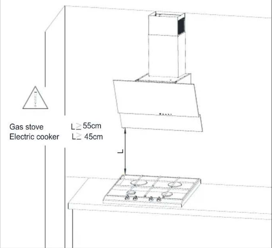
- The height between the lower surface of the hood and upper surface of the stove/oven should not be less than 55 cm for gas hobs and 45 cm for electric hobs.
- Do not operate the hood without aluminum filters and do not remove the filters while it is operated.
- Never touch the hood's lamps after they are operated for a long time. Hot lamps may burn your hand.
- Avoid large flames beneath the product. Otherwise, particles on oil filter may ignite and lead to a fire.
-
Turn on the hobs after placing pans or pots on it. Otherwise, rising heat may deform certain parts of your product.
-
Turn off the hobs before taking -away pans or pots.
- Avoid inflammable materials under the hood.
- Oil may ignite while frying foods. Therefore, be careful about cloths and curtains.
- Never leave the cooker unattended when frying foods; otherwise hot oil may cause fire.
- There is the risk of fire if your hood is not cleaned in the specified periods.
- Be extremely careful and wear gloves when cleaning the hood.
• We advise you to operate the appliance a few minutes before starting to cook in order to increase the suction power. Thus, you shall have a continuous and stable suction power when the vapors arise. - Operate your hood for 15 minutes remove after the end of cooking or frying in order to remove the smell and cooking vapor in the kitchen.
- When the hood is in use, especially together with gas cookers, make sure that environment is ventilated with clean air.
1
Important safety and environmental instructions
- Pay attention not to conn the appliance to the flues used by non-electrical devices. (E.g.: Heater flue).
- This appliance can be used by the children who are at the age of 8 or over and by the people who have limited physical, sensory or mental capacity or who do not have knowledge and experience, as long as they are supervised with regard to safe use of the product or they are instructed accordingly and understand the risks of using the product. Children should not play with the appliance.
- Simultaneous and smoo operation of the hood and another device that require air is only possible when a low pressure of 4 Pa (0.04 mbar) is reached, and thus the reabsorption of the gas is avoided. This can only be achieved by means of air coming from uncovered openings (door, window, ventilation openings or other technical measures). Pay utmost attention to provide sufficient air flow. A flue that provides air ingress/egress is not enough for this purpose.
1.1.3 Children's safety
- Packaging materials are dangerous to children. Keep packaging materials in a safe place out of reach of children.
- Electrical appliances a dangerous to children. Keep children away from the product. Do not allow children play with the appliance.
CAUTION: Accessible parts may heat up when used with a cooking device.
1.2 Intended use
- This appliance is intended for domestic use. It is not suitable for commercial use and it must not be used out of its intended use.
• The manufacturer shall not be liable for any damage caused by improper use or handling.
• Service life of your appliance is 10 years. This is the period required for availability of spare parts for proper functioning of the product.
1
Important safety and environmental instructions
WARNING: Failure to fix the screws in concordance with the instructions provided in the manual may lead to electrical hazards.
1.3 Compliance with WEEE Directive and disposing of the waste product
This product complies with EU WEEE Directive (2012/19/EU). This product bears a classification symbol for waste electrical and electronic equipment (WEEE).
This product has been manufactured with high quality parts and materials which can be reused and are suitable for recycling. Do not dispose of the waste product with normal domestic and other wastes at the end of its service life. Take it to the collection center for the recycling of electrical and electronic equipment. Please consult your local authorities to learn about these collection centers.
Compliance with RoHS Directive:
The product you have purchased complies with EU RoHS Directive (2011/65/EU). It does not contain harmful and prohibited materials specified in the Directive.
1.4 Package information
Package of the product is made of recyclable materials in accordance with our National Legislation. Do not dispose
of the packaging materials together with the domestic or other wastes. Take them to the packaging material collection points designated by the local authorities.
2 Technical specifications of your appliance
Technical data contained in this manual and labels attached to the hood were obtained from measurements and calculations in accordance with the requirements of EU Regulation No. 65/2014 and 66/2014. This appliance complies with the European Directives 2004/108/EC, 2006/95/EC, 2009/125/EC and 2011/65/EU.
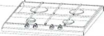
Fig.1 Explanatory figure of the kitchen hood
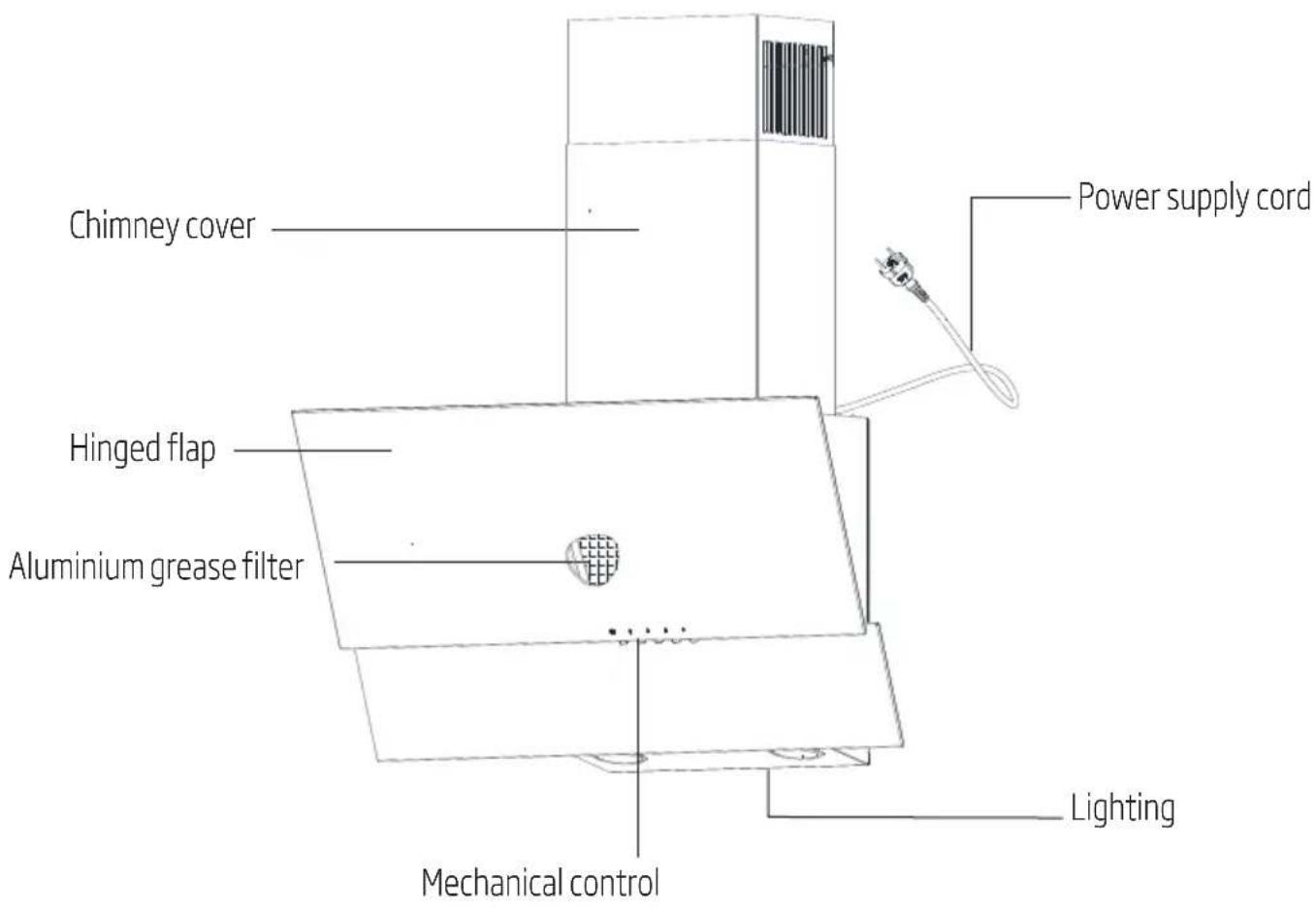
2 Technical specifications of your appliance
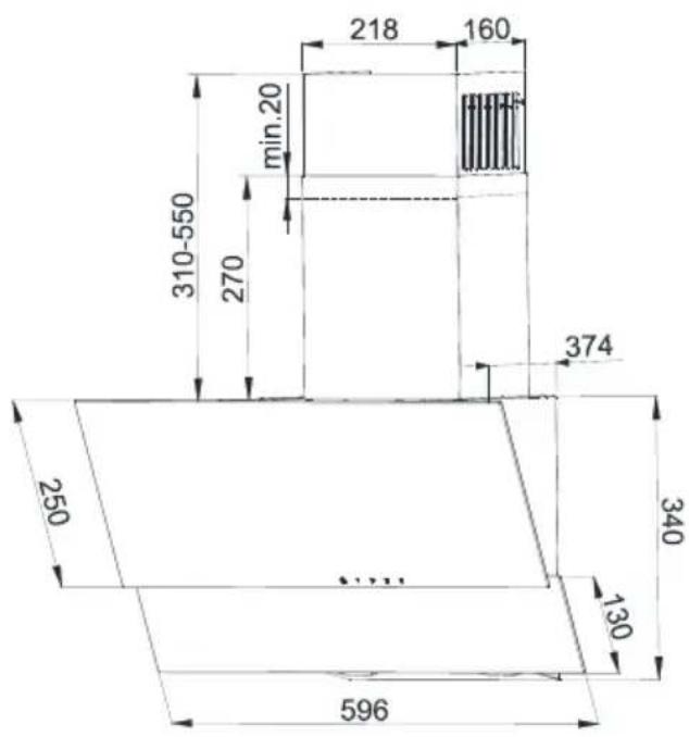
Fig.2 Dimension drawing
3 Operating your appliance
The hood is designed for suction of fumes while preparing meals. The device can be operated in two modes:
As extractor: vapors are removed outside the room by means of a venting pipe. The venting pipe is not available with the device and must be purchased separately.

Use the shortest vapor discharging pipe possible.

The venting pipe shall have the smoothest inner surface as possible (it is not recommended to use pipes of type spiro).

Use a pipe with as few bends as possible (bending angles should not be greater than 90 degrees).

It is not recommended to apply section changes of the pipe (larger to smaller e.g. air outlet ∅150 mm to air outlet ∅120mm).
As absorber: vapors are cleaned of grease and odors before they are returned to the room through the grille on the upper chimney cover. If the hood shall work as an absorber, it is necessary to install an active carbon filter (Fig. 10). The carbon filter is not standard equipment; it must be purchased from a vendor.
4 Installing your appliance

The use of screws or fasteners incompatible with the manual may cause electric shock.
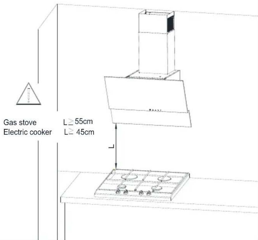
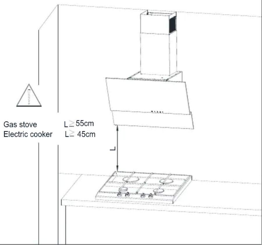
The minimum distance of hood suspension between the surface, on which the kitchenware are positioned on the heating device (gas or electric cooker), and the lowest part of the kitchen hood (Fig. 3) must be not less than 45 cm for cookers with electric power and not less than 55 cm for gas cookers.
If the instruction manual of the heating device contains the requirement of a greater installation distance of the kitchen hood than indicated above, please follow these instructions. The installation of the hood and the hood chimney shield is shown in the drawings (Fig. 4 - Fig. 9)
The hood is equipped with mounting anchors suitable for the majority of the walls and ceilings. The general provisions on the discharge of air from rooms have to be observed during installation.
Fig. 3 Suggested distance from the kitchen cooker.
4 Installing your appliance
Before installation, the following must be done:
- Check that the dimensions of the purchased product are adapted to the selected target spot.
- Disconnect and remove (if possible) the furniture located in the installation area of the hood to get easy access to the ceiling or wall to which the hood is to be fitted. If this is not possible, the elements located near the working area must be secured.
- Verify if there is a plug socket close to the hood installation area and if it is possible to connect the hood to the vent pipe evacuating the vapors outside.
- Verify if the drilling spots do not cover installation wires (electrical, hydraulic, etc.).
- Be equipped with the following tools: measuring tape, pencil, drill/ driver, drill ∅8, screwdriver, bubble level.

The installation must be carried out very carefully, so as not to scratch the chimney cover and the hood.
4.1 Installation works
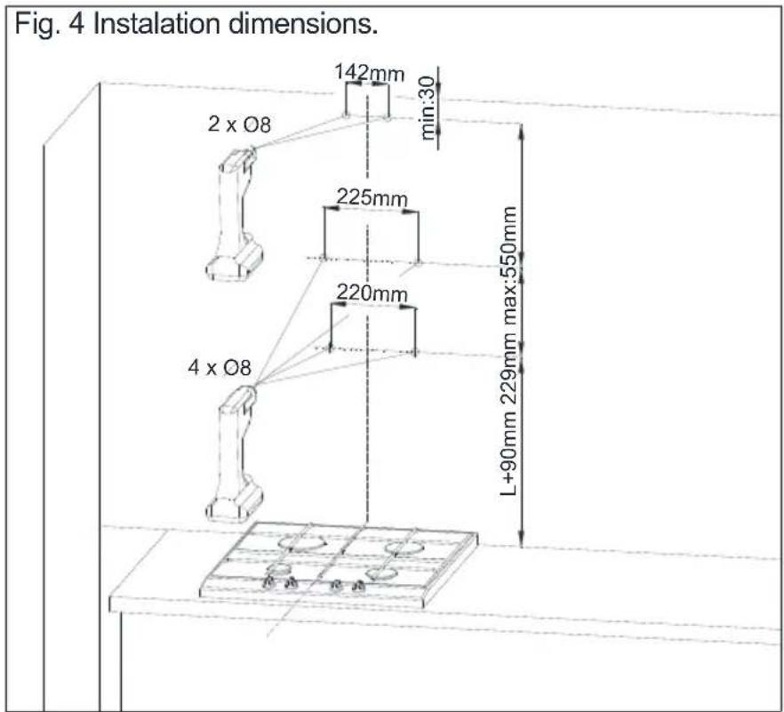
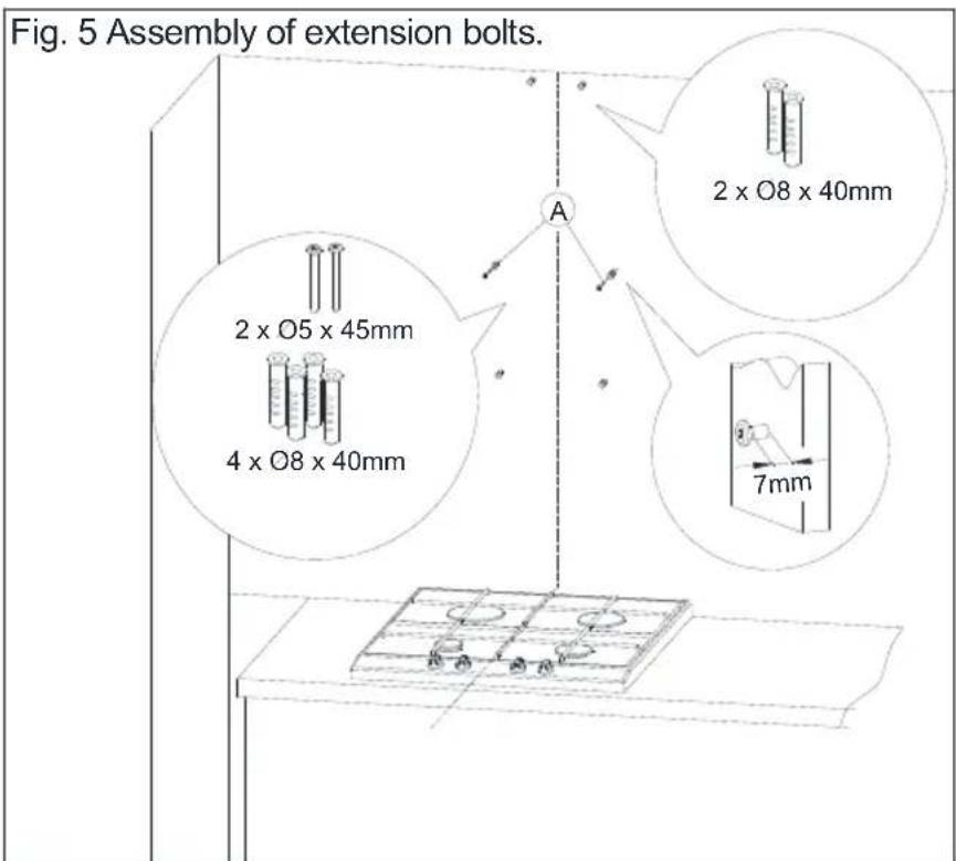
- Determine the heating element axis and transfer it to the wall where the hood will be mounted on. Mark all the specific hood mounting points. Use the drill and drill holes (Fig. 4).
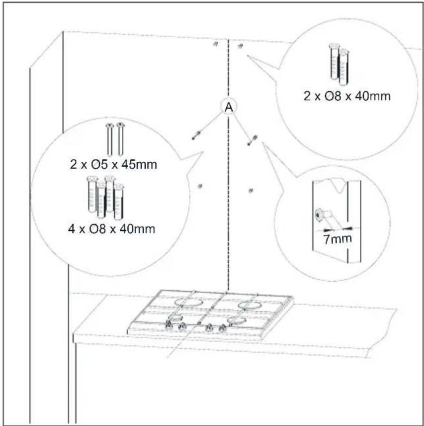
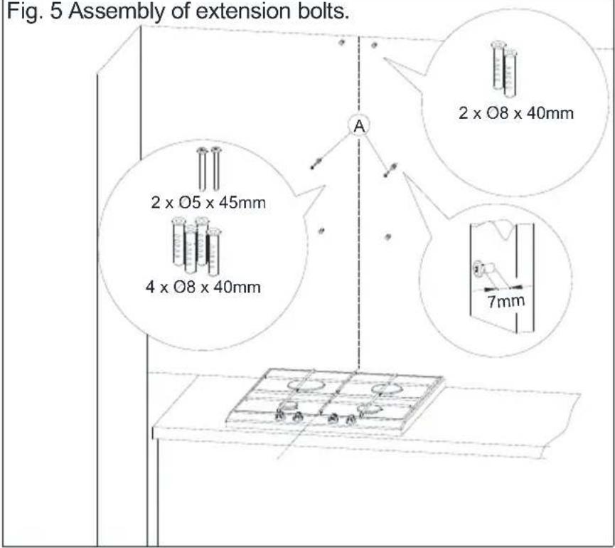
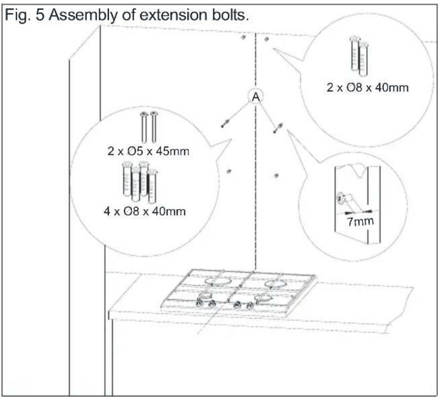
- Insert extension bolts in the openings. In the two holes marked as A insert screws (leaving 7 mm screw length on the outside as in Fig. 5).
- Open the hood flap and remove the grease filter (Fig.6).
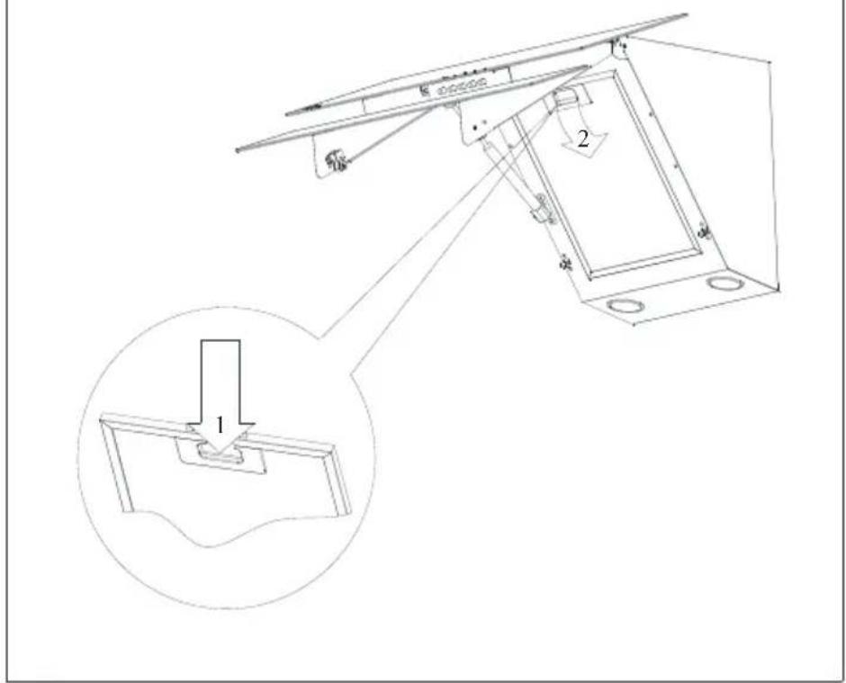
- Screw the chimney cover cramp, hang the hood on two loosely fitted screws (Fig. 7).
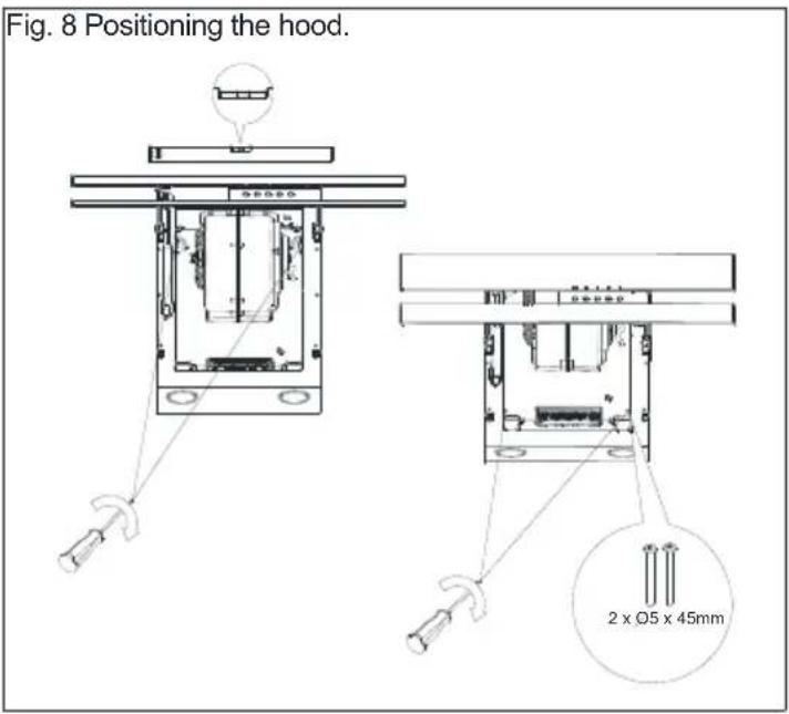
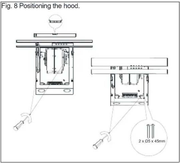
- Place the bubble level on the kitchen hood body. By rotating the elements marked as A, set the hood horizontally in accordance with the indication of the bubble level and then tighten the two loosely fitted screws and the two remaining screws (Fig. 8).
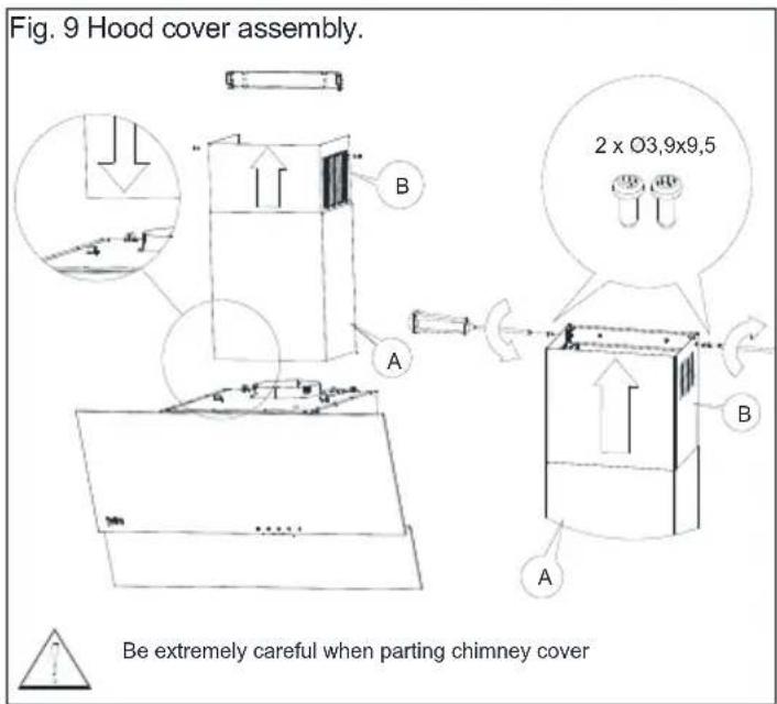
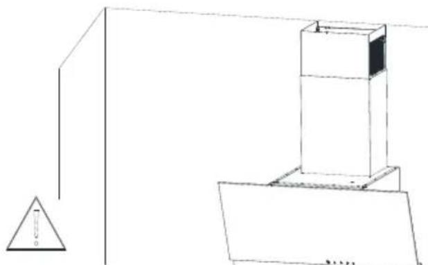
- Put the chimney cover on the body. Then gently pull out the part of the hood that is marked as B upwards until you will be able to screw it to the cramp previously affixed to the wall (Fig. 9).
4 Installing your appliance
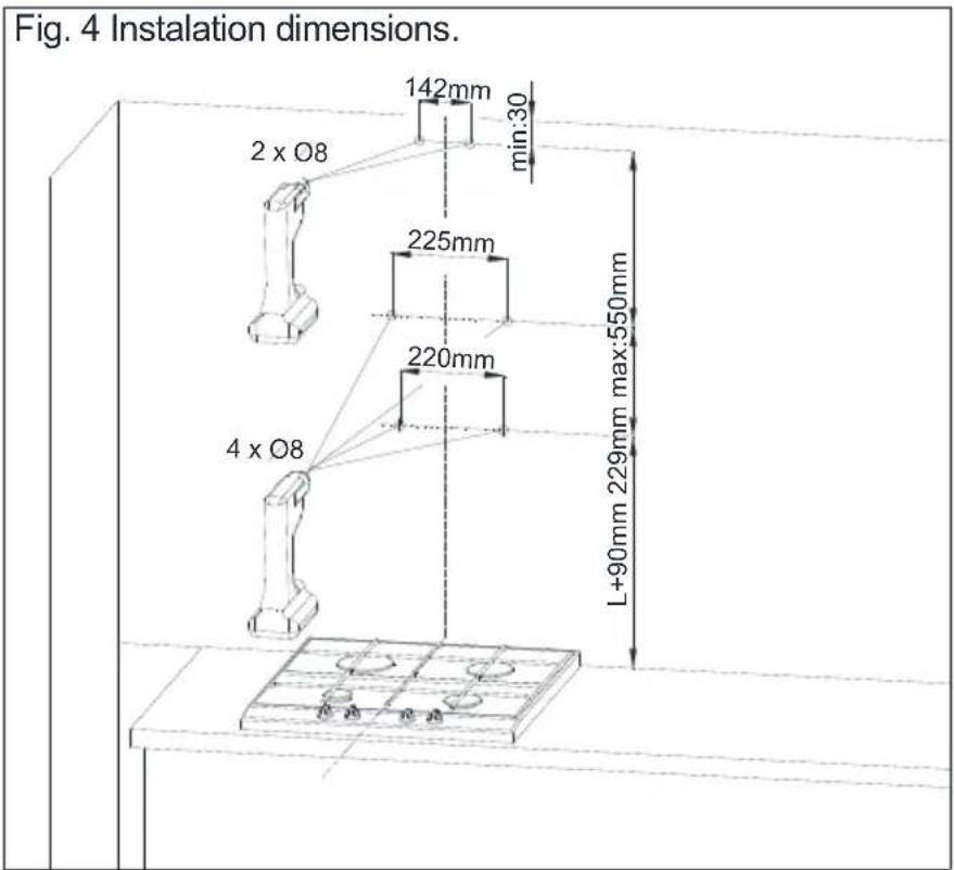
Fig.4 Installation dimensions
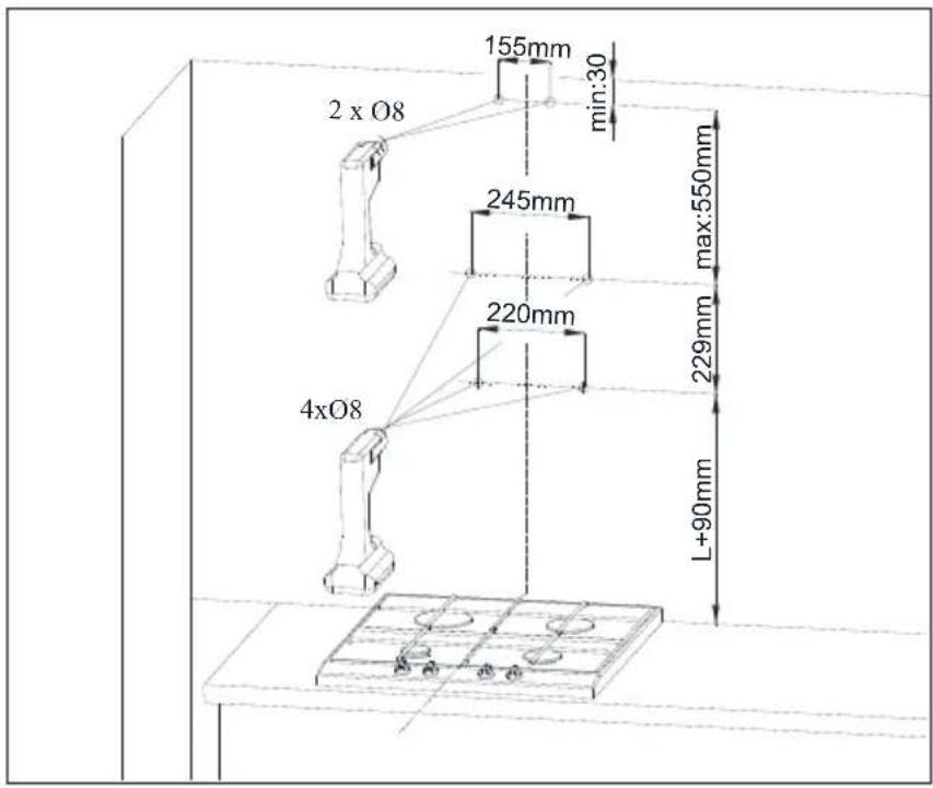
Fig.5 Assembly of extension bolts
4 Installing your appliance
Fig. 4 Installation dimensions.
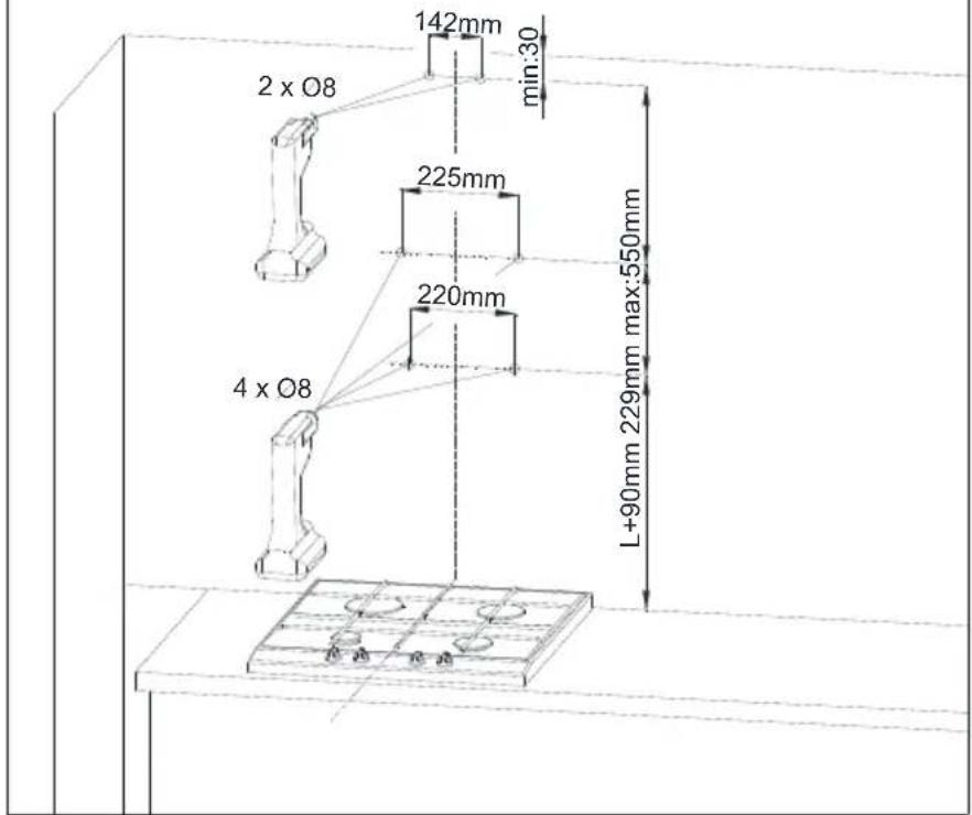
Fig. 5 Assembly of extension bolts.
4 Installing your appliance
Fig. 6 Suspending the hood.

Fig. 7 Dismantling of aluminium grease filter.

4 Installing your appliance

4.2 Electric connection
The mains voltage must correspond to the voltage indicated on the rating plate affixed to the inside of the hood. If the kitchen hood is equipped with a plug, it should be put in a socket connector that meets the requirements of binding regulations and is located in an easily accessible place. If the hood is not fitted with a plug, the installation of the hood should be entrusted to someone with appropriate permissions (e.g. electrician).
5 Cleaning and maintenance
Before carrying out any maintenance operations on the appliance, remove the plug from the wall outlet. The hood should be cleaned with mild cleaning agents, do not use abrasives. Regular maintenance significantly improves the performance and durability of the hood. The hood should be cleaned at least once a month or every 35 hours of hood operation. To clean hood DO NOT USE ALCOHOL-BASED AGENTS. Satin items (inox) should be cleaned with special preparations for that purpose.

Failure to comply with the provisions relating to cleaning of the device and replacement of filters may cause fire risks. It is therefore recommended to comply with the guidelines given herein. The manufacturer is not liable for any damage to the engine or fires caused by improper use.
5.1 Grease Filter
The hood is equipped with an aluminum filter, which retains the fat particles from cooking. The filter can be removed by moving the locks in the direction of the arrows (Fig. 7). The filter should be washed by hand by immersing for 15 minutes in water with dishwashing liquid at a temperature of 40-50°C. After 15 minutes, you can proceed with washing and then rinsing. The filter must be dry before being placed in the hood. The filter can also be washed in a dishwasher. During the washing procedure, the filter may discolor, however it does not affect its filtering properties. If the filter is not cleaned regularly, it reduces the performance of the hood and could cause the risk of fire. The filter should be cleaned at least after each 35 hours of hood operation.
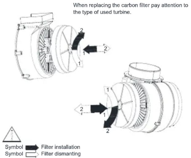
5.2 Carbon filter
The hood can be fitted with an active carbon filter. The carbon filter is applied only in case the hood is not connected to the vent pipe.
The filter should be placed on the turbine casing, as shown in drawing (Fig. 10). The active carbon filter should be replaced every 6 months.

The carbon filter shall not be washed nor regenerated.
Fig. 10 Replacing the carbon filter.
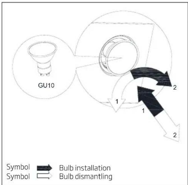
5.3 Replacing of lighting
Prior to any work related to the replacement of lighting, be sure to unplug the power supply. If the hood was previously enabled, you should wait until the light bulbs are cooled, after which you can proceed with the replacement. The process of exchanging the bulbs is shown in Fig. 11.

Before replacing the light bulbs, disconnect the power supply of the hood.

Do not touch the light bulbs when they are hot.

Be careful not to touch the replaced light bulb directly with hands.
5 Cleaning and maintenance
Fig.11 Replacing the lighting
6 Control of hood operation
6.1 Control of the hood
The hood is equipped with a mechanical control.
- Pressing the "0" - disables the turbine hood.
- Pressing the "1" - to turn the turbine hood with a minimum speed.
- Pressing the "2" - turns the turbine hood with an average speed.
- Pressing the "3" - turns the turbine hood at maximum speed.
Higher speed means more air flow.
- Press the button to turn on the lights. Repeat pressing the button to turn off the lighting.
6.2 Methods of reducing the effect of cooking process on the environment
• To reduce Energy consumption, cook with using covers on kitchenware.
- Aluminum filters must be kept clean (recommended length of aluminum filter operation between cleanings is max. 35h of hood operation).
• Take care of permeability of the ventilation pipes.
- The operation level of the turbine when cooking shall be always set to a minimum gear, which will allow removing the fumes at the current intensity of cooking.
7 Solving problems
| Symptoms Cause | Repairing method | |
| During hood operation, the pulsating letter „F” is displayed. | After 35 hours of operation the hood indicates the need for cleaning or replacing the grease filter. | Press and hold for about 8 sec. "-" on the touch control. The filter should be washed in the dishwasher or replace with a new one. |
| The display shows only the symbol “-.” (minus and dot in the right bottom corner), the hood does not respond to disabling. | The touch control has been locked - this feature facilitates the hood cleaning. | To disable the lock, press and hold for about 10 sec the field with the symbol of switching on. |
| No symbol is shown on the display, the hood does not respond to pressing the control fields. | The touch control is probably suspended. | Disconnect the hood from the power supply for about 15 sec. and switch it on again. |
| The display shows the symbol of one of the gears; the hood does not respond to pressing the control fields. | The touch control is probably suspended | Disconnect the hood from the power supply for about 15 sec. and switch it on again. |
| The hood turbine disconnects after 15 min of operation, the display shows a pulsating digit i.e. “1.” (current gear number and dot in the right bottom corner). | The automatic time switch of the touch control has been activated. | To deactivate the time switch, press and hold for about 10 sec the symbol „+”or disable the hood. |
| On fourth gear the digit “4” is pulsating on the display, after 5min the gear is changed into third. | The hood is equipped with a turbo mode, which automatically switches over into third gear after 5 min of operation to save energy. | The turbo gear shall be used only with intensive cooking. |
| The hood can be operated only with use of the control panel, it does not respond to the remote control. | The battery of the remote control is empty or the distance is too long. | Replace the battery with a new one. |
| The hood has very poor vapor suction. | Probably cause is dirty filters. | The grease filter must be cleaned in the dishwasher or replace with a new one. The carbon filter (if present) must be replaced with a new one. |
| One or more light points do not operate. | Defective halogen/ LED bulb. The light | bulb needs to be replaced with a new, compatible with the symbol specified in the instruction manual for the cooker hood. |
| The hood generated excessive noise and vibration. | This may be caused by an incorrect installation of the hood to the wall or kitchen cabinets. Not all provided screws have been used or screws are loosely fitted leaving clearance. | The hood must be mounted to a wall or cabinet by using all the points provided for by the manufacturer. After adjusting the position of the hood horizontally and vertically, tighten all mounting screws. |
| * applies to hoods with touch control. | ||
| If the recommendations above do not solve the problem, contact an authorized home appliances service entitled to repair. Under no circumstances is the hood user entitled to independent repair. A list of service points is included in the warranty card and the website. | ||
4 Montaż okapu
4 Montaż okapu
Symbol Symbol

montaø filtra demontaø filtra
Fig. 3 Suggested distance from the kitchen cooker.
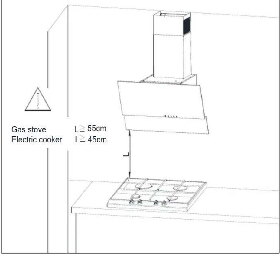
Fig. 6 Suspending the hood.
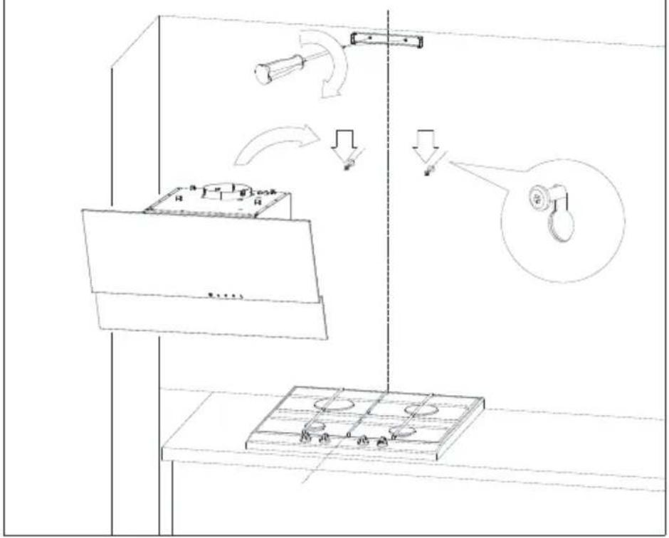
Fig. 7 Dismantling of aluminium grease filter.
Symbol Symbol

Bulb installation
Bulb dismantling
6 Comanda de functionare a hotei
6.1 Comanda hotei
Fig. 3 Suggested distance from the kitchen cooker.
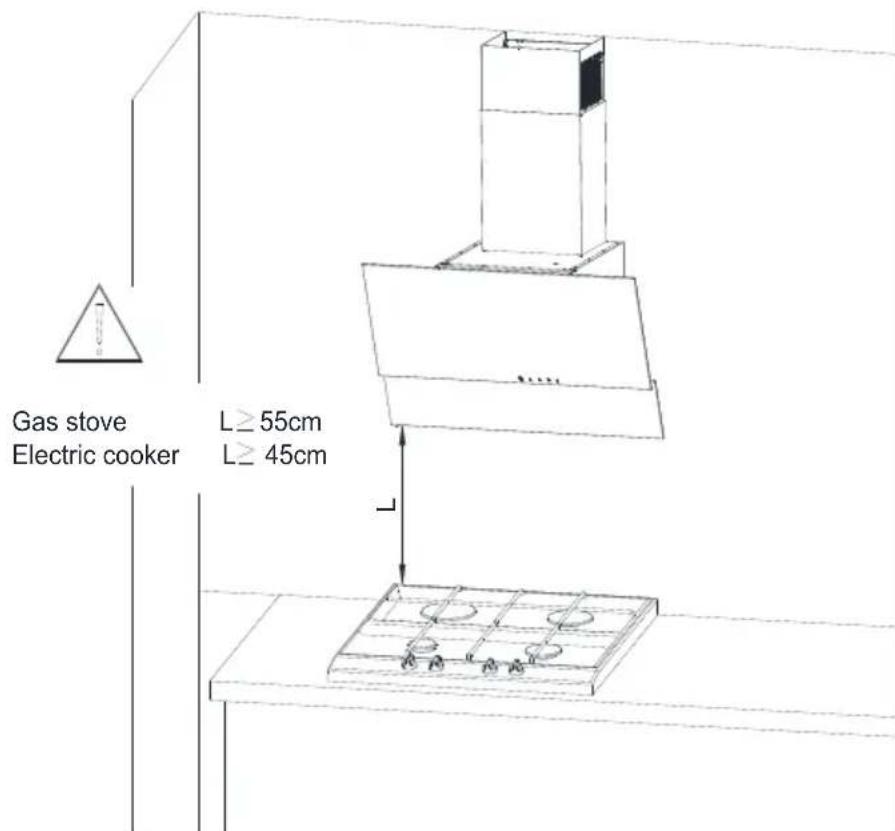
Fig. 6 Suspending the hood.

Fig. 7 Dismantling of aluminium grease filter.

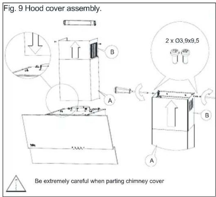
Fig. 3 Suggested distance from the kitchen cooker.
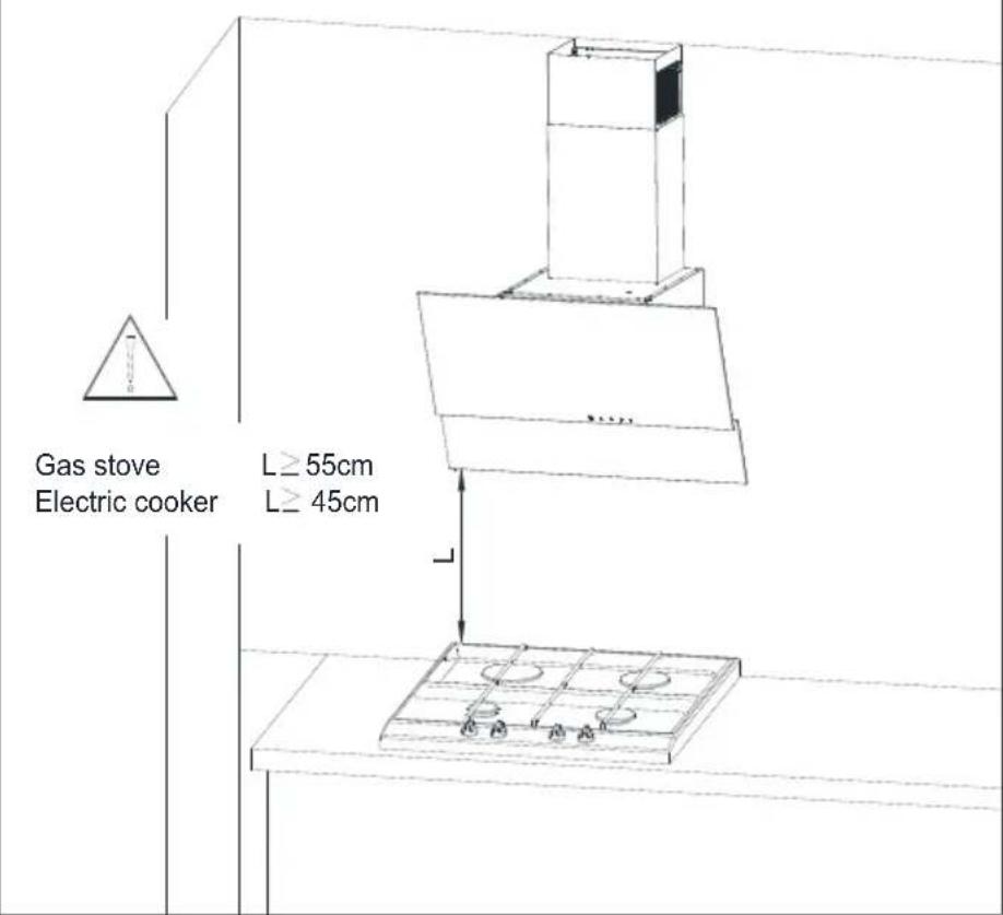
Fig. 6 Suspending the hood.

Fig. 7 Dismantling of aluminium grease filter.
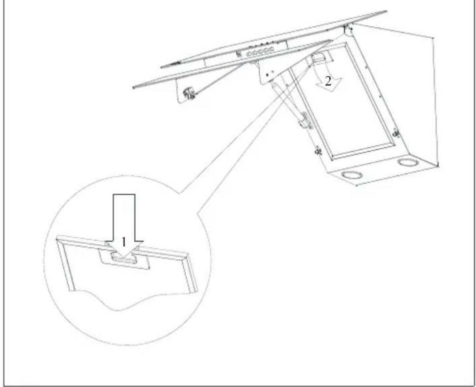

Fig. 3 Suggested distance from the kitchen cooker.
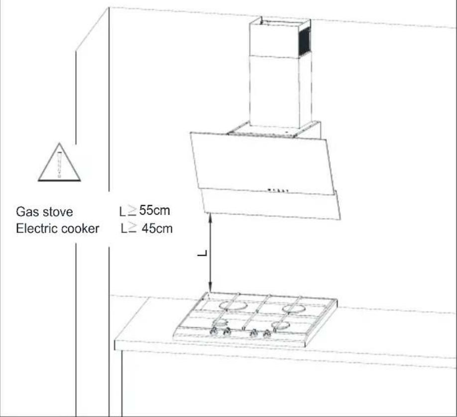
Fig. 6 Suspending the hood.

Fig. 7 Dismantling of aluminium grease filter.

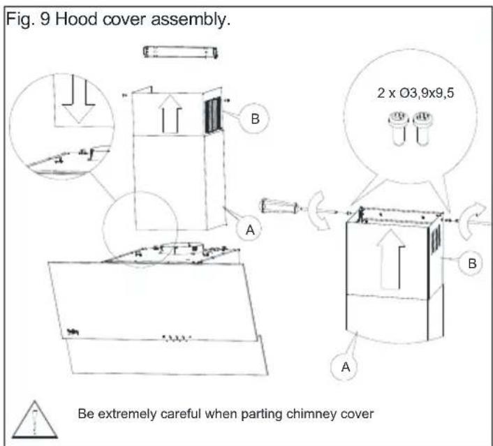
Fig. 3 Suggested distance from the kitchen cooker.
4 Uw apparaat installeren
4 Uw apparaat installeren
4 Uw apparaat installeren
Fig. 6 Suspending the hood.
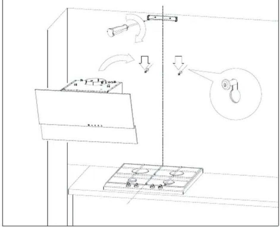
Fig. 7 Dismantling of aluminium grease filter.

4 Uw apparaat installeren


Fig. 3 Suggested distance from the kitchen cooker.
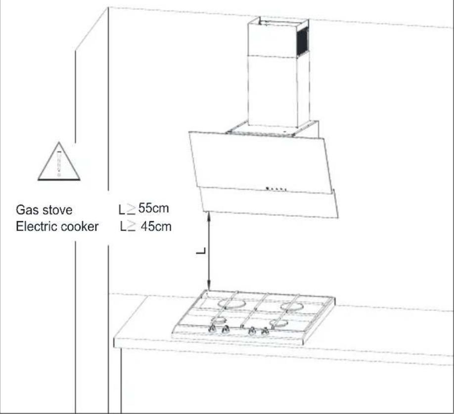
Fig. 6 Suspending the hood.

Fig. 7 Dismantling of aluminium grease filter.


5 Čištění a údržba
Fig. 3 Suggested distance from the kitchen cooker.
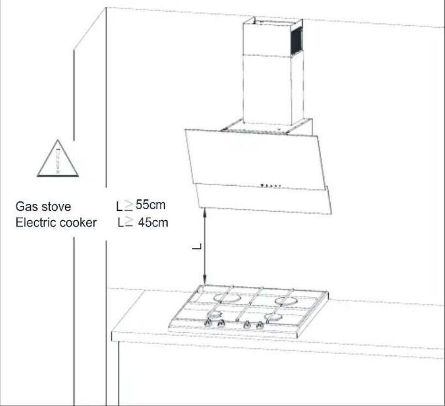
Fig. 6 Suspending the hood.

Fig. 7 Dismantling of aluminium grease filter.


Bulb installation
Bulb dismantling
6 Upravljanje delovanja nape
6.1 Upravljanje nape
Napa je opremljena z mehanskim upravljanjem.
Fig. 3 Suggested distance from the kitchen cooker.
natural_image
Pure technical line drawing of a mechanical assembly without any text, numbers, or symbolsGas stove
Electric cooker
L≥55cm
L≥45cm
natural_image
Technical line drawing of a grid-like structure with four circular holes, no text or symbols presentFig. 6 Suspending the hood.
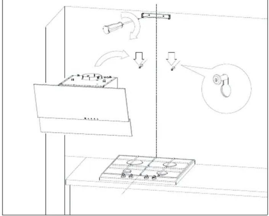
Fig. 7 Dismantling of aluminium grease filter.


5 Čistenie a údržba
Fig. 3 Suggested distance from the kitchen cooker.
4 Установка приладу
4 Установка приладу
4 Установка приладу
Fig. 6 Suspending the hood.

Fig. 7 Dismantling of aluminium grease filter.

4 Установка приладу


Bulb installation
Bulb dismantling