RHV 994 X - Basket ROSIERES - Free user manual and instructions
Find the device manual for free RHV 994 X ROSIERES in PDF.
| Product type | Extractor and recirculation hood |
| Brand | Rosières |
| Model | RHV 994 X |
| Power supply | 230 V ~ 50 Hz (according to label) |
| Suction power | 3 speeds (min, medium, max) |
| Lighting | Halogen lamp 12 V – 20 W (PHILIPS STANDARD LINE 425409) |
| Grease filter | Metal, washable (once a month) |
| Activated carbon filter | Optional for recirculation version, cleanable or disposable |
| Usage version | Extractor (external evacuation) or recirculation (recycling) |
| Chimney | Telescopic, adjustable |
| Minimum distance from cooking hob | 50 cm (electric) / 65 cm (gas or mixed) |
| Control | Push buttons (light on/off, suction OFF, speeds) |
| Maintenance | External cleaning with damp cloth and neutral detergent |
| Safety | Disconnect before maintenance; do not use open flame |
| Spare parts | Carbon filter, halogen lamp (available via after-sales service) |
| Repairability | Power cable replaceable by after-sales service; bulb by user |
| Weight (approximate) | Approximately 12 kg (estimate) |
| Dimensions (W x D x H) | Approximately 90 x 50 x 40 cm (estimate) |
Frequently Asked Questions - RHV 994 X ROSIERES
User questions about RHV 994 X ROSIERES
0 question about this device. Answer the ones you know or ask your own.
Ask a new question about this device
Download the instructions for your Basket in PDF format for free! Find your manual RHV 994 X - ROSIERES and take your electronic device back in hand. On this page are published all the documents necessary for the use of your device. RHV 994 X by ROSIERES.
USER MANUAL RHV 994 X ROSIERES
Instruction on mounting and use
Consult the designs in the front pages referenced in the text by alphabet letters. Closely follow the instructions set out in this manual. All responsibility, for any eventual inconveniences, damages or fires caused by not complying with the instructions in this manual, is declined.
Use
The hood is designed to be utilized either for suction version at external evacuation or filtering version at internal recirculation.
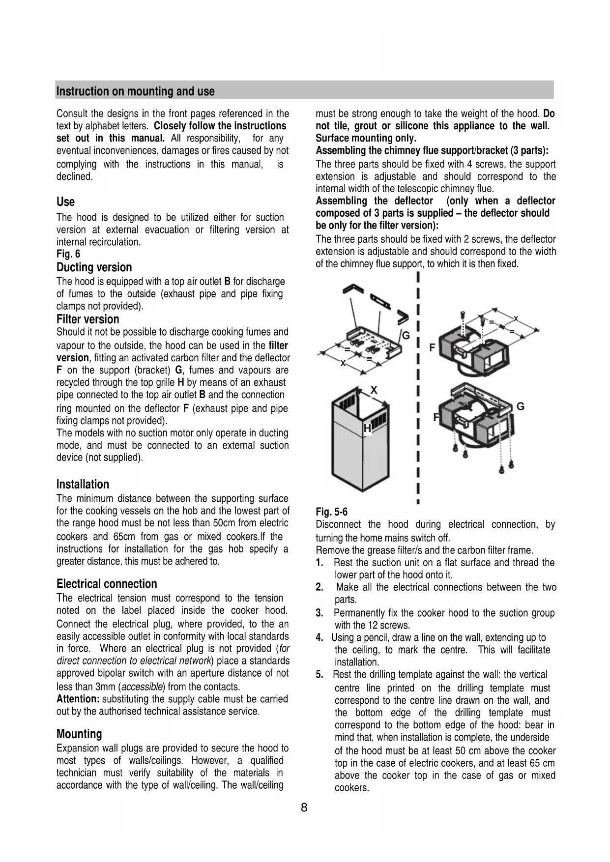
Fig. 6
Ducting version
The hood is equipped with a top air outlet B for discharge of fumes to the outside (exhaust pipe and pipe fixing clamps not provided).
Filter version
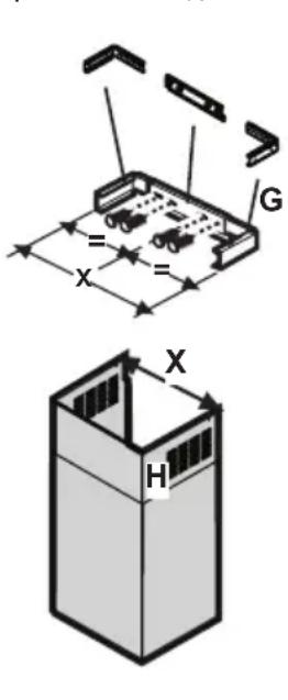
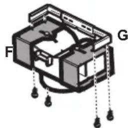
Should it not be possible to discharge cooking fumes and vapour to the outside, the hood can be used in the filter version, fitting an activated carbon filter and the deflector F on the support (bracket) G, fumes and vapours are recycled through the top grille H by means of an exhaust pipe connected to the top air outlet B and the connection ring mounted on the deflector F (exhaust pipe and pipe fixing clamps not provided).
The models with no suction motor only operate in ducting mode, and must be connected to an external suction device (not supplied).
Installation
The minimum distance between the supporting surface for the cooking vessels on the hob and the lowest part of the range hood must be not less than 50cm from electric cookers and 65cm from gas or mixed cookers. If the instructions for installation for the gas hob specify a greater distance, this must be adhered to.
Electrical connection
The electrical tension must correspond to the tension noted on the label placed inside the cooker hood. Connect the electrical plug, where provided, to the an easily accessible outlet in conformity with local standards in force. Where an electrical plug is not provided (for direct connection to electrical network) place a standards approved bipolar switch with an aperture distance of not less than 3mm (accessible) from the contacts.
Attention: substituting the supply cable must be carried out by the authorised technical assistance service.
Mounting
Expansion wall plugs are provided to secure the hood to most types of walls/ceilings. However, a qualified technician must verify suitability of the materials in accordance with the type of wall/ceiling. The wall/ceiling
must be strong enough to take the weight of the hood. Do not tile, grout or silicone this appliance to the wall. Surface mounting only.
Assembling the chimney flue support/bracket (3 parts):
The three parts should be fixed with 4 screws, the support extension is adjustable and should correspond to the internal width of the telescopic chimney flue.
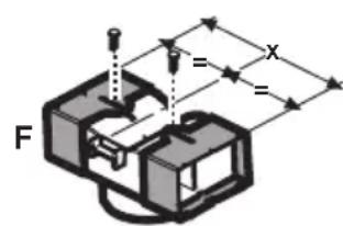
Assembling the deflector (only when a deflector composed of 3 parts is supplied - the deflector should be only for the filter version):
The three parts should be fixed with 2 screws, the deflector extension is adjustable and should correspond to the width of the chimney flue support, to which it is then fixed.
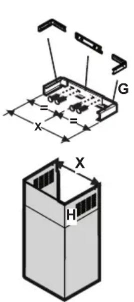
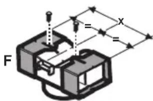
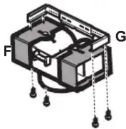
Fig. 5-6
Disconnect the hood during electrical connection, by turning the home mains switch off.
Remove the grease filter/s and the carbon filter frame.
- Rest the suction unit on a flat surface and thread the lower part of the hood onto it.
- Make all the electrical connections between the two parts.
- Permanently fix the cooker hood to the suction group with the 12 screws.
- Using a pencil, draw a line on the wall, extending up to the ceiling, to mark the centre. This will facilitate installation.
-
Rest the drilling template against the wall: the vertical centre line printed on the drilling template must correspond to the centre line drawn on the wall, and the bottom edge of the drilling template must correspond to the bottom edge of the hood: bear in mind that, when installation is complete, the underside of the hood must be at least 50~cm above the cooker top in the case of electric cookers, and at least 65~cm above the cooker top in the case of gas or mixed cookers.
-
Place the lower support bracket on the perforation diagram making it coincide with the traced triangle, mark the two external holes and perforate. Remove the perforation diagram, insert two wall-dowels and fix the support bracket of the hood with two 5x45 mm screws.
-
If supplied dismantled, fix the hooks to the side of the aspiration group with two screws (7a). Hang the hood onto the lower bracket (7b).
-
Adjust the distance of the hood from the wall.
-
Adjust the horizontal position of the hood.
-
Using a pencil mark the cooker hood permanent drill hole inside the suction group (1 or 2 fixing points are necessary for permanent mounting).
-
Remove the hood from the lower bracket.
-
Drill at the point marked (Ø8mm).
-
Insert 1 or 2 wall screw anchors according to requirement.
-
Apply the flues support bracket ^ to the wall adherent to the ceiling, use the flues support bracket as a perforation diagram (if present, the small slot on the support must coincide with the line drawn previously on the wall) and mark two holes with a pencil. Make the holes (08mm), and insert 2 dowels.
-
Fix the chimney support bracket to the wall using two 5x45mm screws.
-
Hook the hood onto the bottom bracket.
-
Fix the hood into its final position on the wall (ABSOLUTELY ESSENTIAL).
-
Connect a pipe (pipe and pipe clamps not provided, to be purchased separately) for discharge of fumes to the connection ring located over the suction motor unit.
If the hood is to be used in ducting version, the other end of the pipe must be connected to a device expelling the fumes to the outside. If the hood is to be used in filter version, then fix the deflector F to the chimney support bracket G and connect the other extremity of the pipe to the connection ring placed on the deflector F.
-
Connect the electricity.
-
Apply the chimney stacks and fasten them at the top to the chimney support, G (20b) using 2 screws (20a)
Only for the model with control panel on the flue:
Only if the control panel is not mounted on the lower flue:
Insert the small plate of the commands coming from the motor group into the slot of the flue, from the interior to the exterior (20c).
Connect the control panel to the small plate.
Attention! The pin of the small plate terminal MUST correspond to the hole made in the connection plinth on the back of the control panel.
Only if the control panel is already mounted on the lower flue:
Connect the control panel to the electronic box of the hood.
Attention! The pin of the small plate MUST correspond to the hole made in the connection plinth on the electronic box (20d).
-
Slide the bottom section of the chimney down until it completely covers the suction unit and slots into the housing provided on top of the hood.
-
Fix the lower section of the chimney with two screws. Remount the carbon filter frame and the fat/s filter/s and check the perfect functioning of the hood.
Description of the hood
Fig. 1
- Control panel
- Grease filter
- Grease filter release handle
- Halogen lamp
- Vapour screen
- Telescopic chimney
- Air outlet (used for filter version only)
Operation
Use the high suction speed in cases of concentrated kitchen vapours. It is recommended that the cooker hood suction is switched on for 5 minutes prior to cooking and to leave in operation during cooking and for another 15 minutes approximately after terminating cooking.
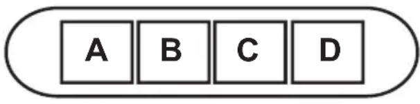
Model with button panel
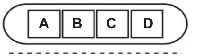
DCBAE
A. on/off light switch
B. on/off aspiration switch and minimum power selection
B+C. medium power selection aspiration switch
B+D. maximum power selection aspiration switch
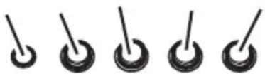
E. operating gauge (foreseen in the model with round buttons)
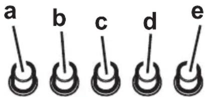
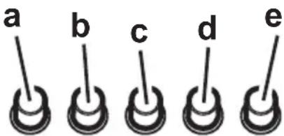
a. on/off light switch
b. off aspiration switch
c. minimum power selection aspiration switch
d. medium power selection aspiration switch
e. maximum power selection aspiration switch
Maintenance
Prior to any maintenance operation ensure that the cooker hood is disconnected from the power supply.
Cleaning
The cooker hood should be cleaned regularly internally and externally. Clean using the cloth dampened with neutral liquid detergent. Do not use abrasive products.
DO NOT USE ALCOHOL!
Warning: Failure to carry out the basic standards of the cleaning of the cooker hood and replacement of the filters may cause fire risks.
Therefore we recommend observing these instructions.
Grease filter
Fig. 2
This must be cleaned once a month (or when the filter saturation indication system - if envisaged on the model in possession - indicates this necessity) using non aggressive detergents, either by hand or in the dishwasher, which must be set to a low temperature and a short cycle.
When washed in a dishwasher, the grease filter may discolour slightly, but this does not affect its filtering capacity. To remove the grease filter B, pull the spring release handle.
Charcoal filter (filter version only)
Fig. 3
It absorbs unpleasant odours caused by cooking.
The charcoal filter can be washed once every two months (or when the filter saturation indication system - if envisaged on the model in possession - indicates this necessity) using hot water and a suitable detergent, or in a dishwasher at 65^ (if the dishwasher is used, select the full cycle function and leave dishes out).
Eliminate excess water without damaging the filter, then remove the mattress located inside the plastic frame and put it in the oven for 10 minutes at 100^ to dry completely. Replace the mattress every 3 years and when the cloth is damaged. Remove the filter holder frame by turning the knobs (g) 90^ that affix the chimney to the cooker hood.
Insert the pad (i) of activated carbon into the frame (h) and fit the whole back into its housing (j).
It is possible to use a traditional carbon filter, neither washable nor regenerable, to be replaced every 3 - 4 months.
The filter holder frame of the carbon filter is welded together; the eventual frame supplied with the hood is not, therefore, to be used.
Insert it into its housing and fix it turning the 2 plastic knobs.
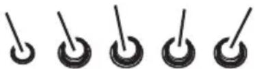
Replacing lamps
Fig. 4
Disconnect the hood from the electricity.
Warning! Prior to touching the light bulbs ensure they are cooled down.
- Use a small screwdriver as a lever on the borders of the lamp in order to remove the lightbulb.
- Slide out the lightbulb to be replaced and replace with a new 12V 20W 30^ Ø35 12V GU4 PHILIPS STANDARD LINE code 425409.
- Carry out the replacement and mount the new lightbulb by following instructions in the reverse.
If the lights do not work, make sure that the lamps are fitted properly into their housings before you call for technical assistance.
Caution
Never use the hood without the grill mounted!
This appliance is designed to be operated by adults. Children should not be allowed to tamper with the controls or play with the appliance.
The premises must have sufficient ventilation when the kitchen hood is used at the same time as other apparatuses that use gas and other fuels.
The sucked air must not be conveyed in a conduit used for discharging fumes produced by apparatuses fuelled by gas or other fuels.
Cooking food on the flame under the hood is severely prohibited.
The use of open flame damages the filters and can cause a fire; it must therefore be avoided in any case.
Frying must be carried out under control in order to prevent overheated oil catching fire.
Keep strictly to the regulations envisaged by the competent local authority as far as the technical and safety measures to adopt for discharging fumes are concerned.
The hood is to be cleaned frequently both internally and externally.
Failure to observe the regulations about cleaning the hood and substituting and cleaning the filters can lead to the risk of fire.
Any responsibility is declined for possible inconveniences, damage or fire caused to the apparatus deriving from failure to observe the instructions shown in this manual.
This appliance is marked according to the European directive 2002/96/EC on Waste Electrical and Electronic Equipment (WEEE). By ensuring this product is disposed of correctly, you will help prevent potential negative consequences for the environment and human health, which could otherwise be caused by inappropriate waste handling of this product.
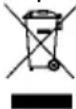
The symbol on the product, or on the documents accompanying the product, indicates that this appliance may not be treated as household waste. Instead it shall be handed over to the applicable collection point for the recycling of electrical and electronic equipment. Disposal must be carried out in accordance with local environmental regulations for waste disposal.
For more detailed information about treatment, recovery and recycling of this product, please contact your local city office, your household waste disposal service or the shop where you purchased the product.
Assembler le support cheminée (3 parties):
CoeHnTe 3 YacTn DeepneKTopa 2-My WypynAmN, WnpHa DeepneKTopa DoJXHa 6bItb paBHO JnPHe ONOpHOro KPOHtEiHa NOD KaMH.
Pnc. 5-6
OTcoeHNHTBbITAKKyOTcETN,dEChTByHaΦa3bl 3JNEKTPnueckoro coeHNHeHnHa o6IeM 3JNeKTPOuNTe.
Chmnte 0nBtp/b3aepKKn Knpa N depKaTeNb yroIbHOro 0nJbTpTa.
- YIIOXKHTe BbITJXH0N 6JOK Ha IIOCKOE OCHOBAHHe N BCTaBbTe B HrO, CHN3y, HIXHHIOY aCtB bItJXKN.
- BbINOHNHe 3NeKtpnueckoe CoeINHeHne DByx YacteI.
- 3akpeINTe OKOHaTeJIbHO BbITJKKy K BbITJKHOMy 6noey Uppynamn.
-
KapaHdaWOM, HauepTIne Ha CTHe Do NOTOnKa JINHHIO, COOTBETCTByIOUyIO OCEBOJ JINHHI yCTaHaBJIbAEMOIBbITXKN: 3TO 06JIerHT ONepaUNI NO yCTaHOBKe.
-
PpncloHnte 7a6JIOH K CTeHe: cpeHnA BepTKKaIbHa JINHn, HaneCenHnA Ha 7a6JIOH DOJXHa COBnaDaTb C OCEBOB BepTKKaIbHOJ INHnei, HaupeuHHoH Ha CTeHe; KpOme TOrO, HxKHe J KpOMKa 7a6JHOHa COOTBetCTByET HxKHe IpaHn BBITJKKN. ImeTe B BuNy, YTO NO 3aBepUeHNYcTaHOBKn HxKHe rpaHb BblTJKKN DOJXHa HaxOHTbcr Ha pacctOHRn He Mehee 50 CM OT 3JIeKTPnuECKo NITbI, 65 CM OTra3OBOn NKOMbHnpOBaHHo NITbI
- IIOJIOXHTE HIXHHN OONpHbI KPOHHTeH Ha 7a6JIOH B COOTBETCTBNN C 3aHTpHXOBAHHBIM npraMOYOrbHkOM, OTMeTbTe Dba BHEuHnx OTBepCTnI N pOcBepNTe INx, CHMHTe 7a6JIOH, BCTaBBTe 2 IIO6eN I 3aKpeNTe ONOpHbI KPOHHTeH NOB bblrKky 2-My 7uypyamn 5x45 MM.
- Ecn OHN NOCTaBHeHbI B pa3o6paHHOM BnDE, 3aKpeNITE NOBBeCKN BbITJXHO 6JOKa DByMg WypynAMn (7a).HaJeHbTe BbITJXKKy Ha HIXKbI IN KPOHHTeH (7b).
- OtperynpytepacctoHneBbITKIOCTeHbI
- OtperynpyTe noJoxeHne BbITaKKn NO Tropn30HTan
10.ИЗнутPN BbITЯЖHOrO 6nOKa,OTMeTbTe KapaHdaWOM OTBepCTne ДЯ OKOHyATEJIbHOrO KpenNeHnB BbITЯЖKn (1 INI 2 MeCTa DЯ OKOHyATEJIbHOrO KpenJIeHnA). - CHIMITE BBITKky C HIXKHERO KPOHHTeHa.
- Iopaa3meTke npoJeIaIe Te OTBepCTne (U 8 MM).
- BCTaBbTe 1 uJN 2 dOBeJRA, KAK 3TO Heo6xoJMo.
14.3aKpeHnTe onOpHbI KPOHHTeH NOD KaMHbI G"K CTHe CmExH0 K NOTOKy; NcNoJb3yHr Te ONOpHbIKPOHHTeH NOD KaMHbIB KauEcTBe WabHOHa (ecNIO OHO IMeeTcR, MaJoe OBaJIbHOe OTBepCTne B KPOHHTeHE DOJXHO COOTBETCTBOBaTb C JINHnei, paHee NahepueHHo Ha CTHe), OTMeTbTe KapaHdaWOM 2 OTBepCTnI, IpOdenaiTe OTBepCTnI (X8 MM), BCTABtE 2 DIO6eJIa. - 3akpenite onopnbik kpohsteHH noKamH KCTHe 2-My wypynamn 5x45 MM.
- NpOdBecnte BbITaKky K HnXhEmy KoPOnHTeHy.
- 3akpenite OKOHyatelbHO BbyTJkky K CTeHE (HEINPEMEHHO HEOXOIMO!).
- POnBEdnTe BeHTnIaHNoHHyTo Tpy6y (Tpy6a H XOMyTbI KpeJIeHnA He BXoJrT B KOMnJIeKT NOCTaBKn) K BbITaKHO BTyIke, paCNOJoxEHHo HAd 6bOKOM 3JeKTPoDBnAratEna. POnBEdnTe DpyroI KOHeU Tpy6bIK CnCTeMe OTBOJa, B Cnyuae IcNoJIb3OBAHnB bITaKKn B pExKIMe OTBOJa DbIMOB HApxKy. EcIn BBy XOTnTE NcNoIb3OBAtB BbITaKky B peKIMe peuNpKyIaMn BO3Dyxa, 3akpeINte DeΦJIeKTop F K KPOHHTeHy G n POnBEdnTe DpyroI KOHeU Tpy6bIK COeDNHInTeJbHO BTyIke, paCNOJoxEHnOH Ha DeΦJIeKTope F.
- BbINOHNHe 3JNEKTPnueeCKoe NOdKJIuOeHne.
- NocTaBbTe KaMnHbI 3aKpeNITe INx 2-My wypynamn
(20a) K onopHomy kpoHHTeHy G (20b).
ToIbKO K Moden C nHaHEnBIO ynpaBneHnHa KaMnHe:
ToIbKO B clyuae, ecn naneHb ynpaBneHna He CMOHTnpoBaH yke Ha HxKHeM KAMHe:
PpOyCTnTe PnOcKn PpOBoD ynpaBneHn O T MOTOPHO 6JIOKa YpeE3 PpOyUINHy N3HyTpN KaMHa HApYk (20c).
PoiocdHnTe PIOCKN IPOBOK K NaHeJIynpabJIeHnI.
BHMaHne! Wtbp WTeKKepa NIOCKoro npoBoDa DOJXEH COOTBeTCTBOBaTb OTBepCTNPO3beMa, IMeOuTeOcRc3aDn NaHeN ynpaBHeHn.
ToIbKO B cnyae, ecn naHen ynpaBneHna yKe CMOHTnpoBaHa HnxKHeM kAMHe:
IopcoeMHnTe naHb ynpaBHeHnK 3JneKTpoHHo Kopo6ke BbITKaKN.
BHHMaHHe! WtBipb WTeKKepa NnOcKOro npOBoDa IOJKeH COOTBeTCTBOBaT OTBepCTNIO pa3beMa, IMeUeRoCA Ha 3JIeKTPoHHo Kopo6Ke (20 d).
- Onycntte HIXKHO CEKUHO KAMHa (TeM CambIM NOKpbIBaI NOHOCbIO BbITXHOI 6NOK) I pa3MeCTnte ee B COOTBEcTBByOuEM rHe3De HaB bITXKOI.
22.3aKpeHnTe HnKHOIO CeKuHO KAMHa DByMa Uypyamn. YcTaHOBnTe BHOb DePkaTeNb yOrIbHoro FnIbTp a n FnIbTp/bl 3aepxKn Xnpa N npOBepbTe NCppaBHe OyHKUHOHnOBAHne BbITJKKN.
OnncahHe BbITJKKN
Pnc.1
- NaHeIb ynpaBneHnra
- ΦινλTp 3aDéρχκη κηρα
- Puyka OTeunneHnФиньТра 3aIepKKn Knpa
- TanooreHHaJ lamna
- OtknDHOH 3KpaH
- KamNH TeJIeCKOnIueCKn
- BbIOB BO3Oyxa (TOIbKO BpeXmpeuNpyn)
ФункционpoBaHne
No3yTEcb HHTeHCBHbIM peKIMOM pa60TbBblJkN B Cnyae OcO6o BblCOKO KOHcEHTpaUN KyxOHhIX nCnapeHm. Mbl peKOMEHyEM BKIOUHTbBblJkKy 3a 5 MNHyT Do Hauana npouceca npiroTOBHeHn NtNi N OCTaBtB ee BKIOUeHHoB TeueHne 15 MNHyT np6Iu3nteNbHO no OKOHuaHN npouceca.
Moelb c KlaBnHoi nHaHeIbIO
DCBAE
A-Knabuwa BKN/BbIKJ noCBeTkn
B-Knabuwa BblKJI/BKJI BblTJxKNI nepeKnOueHna MmHmMaJIbHyIO MOUHOCTb
B+C - KlaBnIa nepeKluOeHna Ha cpeHIO MOUHOCTb
B+D-KIaBnua nepeKIOueHnHa MaKcImaJIbHyo MOuHOCTb
E.Индкатop pa6otbI (npeDyCMOTpeH B moeJnx C KpyIbIMN KnaBnAmN).
a.BKl/BbIKI npocBETkn
b.BbIKJ3neKtpoDburatalee
BhImaHHe! PpeKdyeem npkaTbCRA K naMaM y6eIntecbBTOM, YTO OHN OCTblIN.
BbHbTe IaMny npn NMOU H6OJIbWOn OTBeptKc HOKeBOI rOIOBkoI INI IOo6HOrHnCTpyMeHTa.
3aMeHnTe npeperopeBwuyo lamny.
IcnoB3yIte NIIb HOBYIO ranoreHHyIO IaMny Tnna PHILIPS STANDARD LINE, K0d 425409, Ha 12 B, 20 BT 30e X35 12B GU4.
BCTaBBTe HOBUyIaMny, BbINOHNB OepaunIO B 6paTHoN NocJeIOBaTeJIbHOCTN.
Ecnn cnctema noocBeTKe He pa6oTaet, npoBepbTe KoppeKTHyU yCTaHOBky JAmn B rHe3dax, npexKe Yem 6paNTbcraB u cHTp TEXHueckoi NOMOUI.
Bhumahne!
He donyckaetc nCnoJIb3ObaTb BbITKa, ecn peWetka HenpabInbHo yCTaHOBNeHa!
Obecnebte HaedxHyo BeHTnIaHIO nOmeueHn, ecN BblncnoB3yTe BbITaxkOndHOBPemEHcDpyrMM np6opam, mHeUzmm Ra3OBoe NtAHne Nn NtAHne dpyrMM BIDAMn rOpioHero.
BbIraHbAeMbI Bo3DyX He DoJxHe BbI6paCbIbATbcr Ype3 Bo3DyXOBoD, NcNoIb3yEmbI dJa BbIBOa DblMOB OT np6OpOB C r30BbIM NTaHnEM NII NTaHnEM dpYmM BIDAMN roPouero.
Kateropueeckn 3anpeuaetcJxapntb nIuHa nIaMeHn IOD BblTjXkOi.
IcnoJIb3OBAHHe CBO6oJHO IpAmEH BpeH0 IIN
PnIbTPOB N MOxET CTaTB PpUHNo IOXapa, NO3tOMy
N36eRaIte 3TORO B JIO6OM Clyuae.
XapeHbe B MacNe IOJxHO 6bITb CdeNaHO NOKHTPOJeM BO N36eKaHne TORO, YTO6bl NepepeToe MacNo BOCJIaMeHaJIOCb.
YTO KacaetcMepNoTexnke6e3onacHocTnIyBbipoca DbIMOB, PnpDepKnBaNTecb CTPoro npabIN, PpeDycmOTpeHHbIXperlameHTOM MeCThblX KOMnTeHTHbIX BnaCTeN.
BbInonHnIe TepnoDnueckn BnyTpehHIO u BHeUHIO OOHTKy BbITJKKN.
Heco6IIODeHne IpaBnI NO OChTKe BbITJxKn I IO 3aMeHe n 3aUcTKe QnJIbTpOB MoKet PpNBecTn K BO3HnKHObeHmO noXapa.
Mbl CHImaem C c6eBCaKyO OTBeTCTBHeHOctb 3a HeNoJaKn, yUep6 uNn NoXap, YBnaIOuIeCra CneDCTBnEM Heco6JIouDeHn NHTpyKcni, PpNBedeHHbIX B DaHHOM pyKOBOdCTBe.
JaHHoe 3dEne IpOMapKIpOBAHO B COOTBeTCTBnC EbponeckoI Dnpektboi 2002/96/EC no ytnin3aun 3NeKtpnueckoro n 3NeKtponHoro 6OpudobAHn (WEEE).
Obecneiv npabnIbHyu ytnn3auno daHoro n3denn, Bbl nOMOxTe npedotBpaTntb NOTeHuaNbHbIe HeratNBbIe nocnectBna IIN OKpykaoucpeDbI 3dopOBbY eNoBeka, KOtOpBie MOrN 6bl IMeTb MeCTO B npOTUBHom cnyae.

CNMBON

CAMOM
m3dEJIIN
NNN
COnpOBOuNTeBHOJOKymHtauN yKa3bIbAet, YTO npYTuIN3aun DaHHoro N3deNn C Hm HeIb3ra ObpaataBCaKc O6bHbIMN 6bITOBbIMN OTXoamn BMeCTO 3TOTO,eroCNeDyET CdaBaTB B COOTBetCTByUoHn PnyKT PnpEMKn3JeKTPnuEckoro N3eKtpOHHO 6OpdyOBaHn DnPaNoCneDuOSeYTuIN3aun.
CdaaHa CnOM DOJIKHa PpOu3BOUITbC B COOTBcTCTBm C MeCTHbIMN npaBUNAMN NO YTuIN3aCIN OTXoIDOB.
3a 6oJee noDpo6Hoi HΦopMaζnei O npaBnIax o6paueHnC TaKIMN n3dEInyMn, IN yTnIN3aun N nepepa6OTKn o6paauTeCb B MeCTbE opraHb IBaCTN, B cnjX6by NO yTnIN3aun OTxOIOB INB MaRa3H, B KOTOpOM Bbl npio6peJIu DaHHoe n3dEIne.