LSW350B - TV Mount LG - Free user manual and instructions
Find the device manual for free LSW350B LG in PDF.
| Brand | LG |
| Model | LSW350B |
| Product type | TV wall mount |
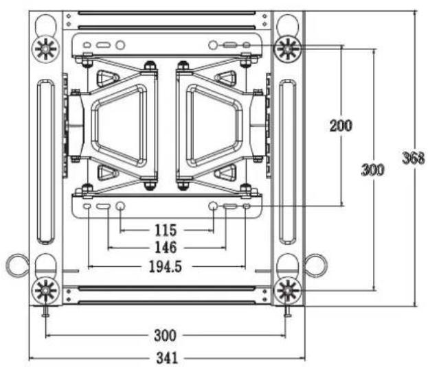
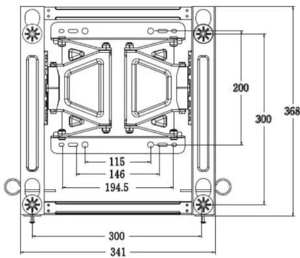
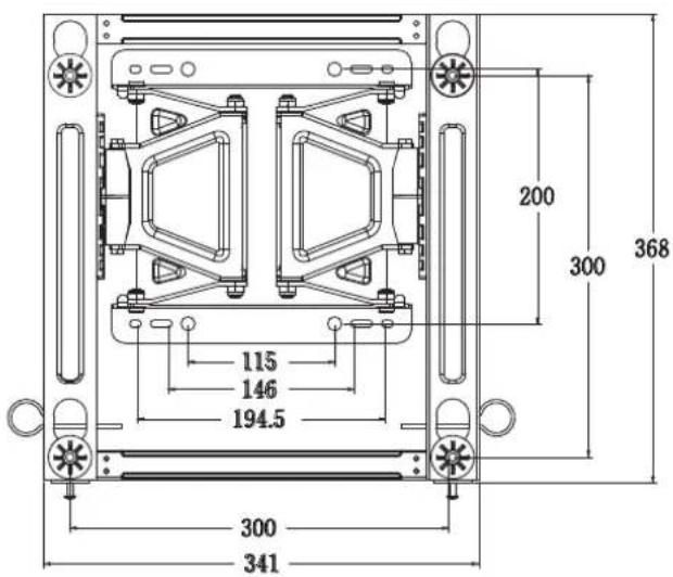
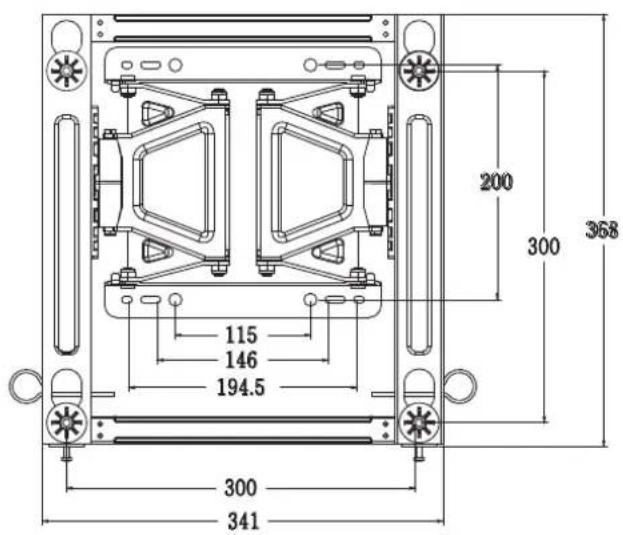
| VESA standard | 300 x 300 mm |
| Maximum load | 50 kg |
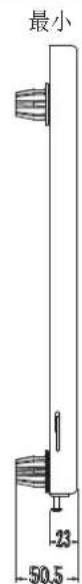
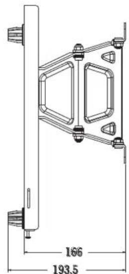
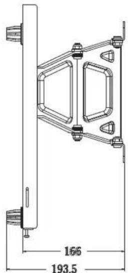
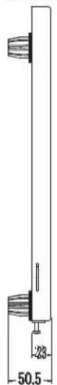
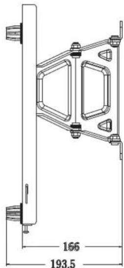
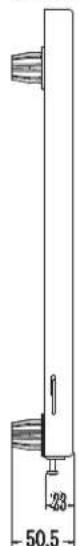
| Dimensions (W x H x D) | 341 x 368 x 23 mm |
| Product weight | 3.2 kg |
| Material | Steel |
| Finish | Black |
| Tilt angle | Not tiltable (fixed) |
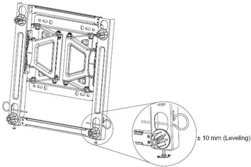
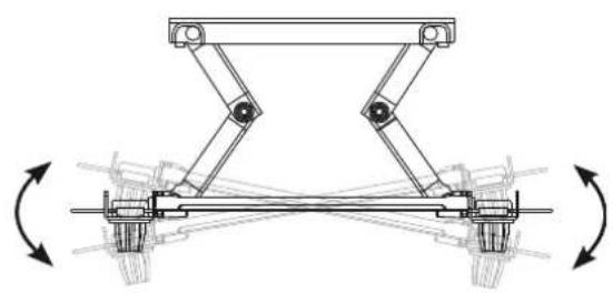
| Horizontal adjustment | ± 10 mm |
| Landscape/portrait orientation | Landscape only (rotation limited to 90°) |
| Wall compatibility | Concrete, lightweight concrete, stone, brick, hollow blocks |
| Installation | Recommended by a qualified installer |
| Package contents | Wall mount, 6 anchor bolts, 6 fixing screws, 2 safety straps, 4 spacers, 4 protection pads, 4 spacer screws (M6 x 43 mm), installation manual |
| Required tools | Phillips screwdriver (manual or electric), 8 mm socket wrench, level, drill, ∅ 8 mm drill bit (for concrete), hammer |
| Maintenance | Clean with a dry cloth; do not use a damp cloth |
| Safety | Do not hang from the mount; install only on vertical walls; use the provided screws; do not overtighten |
Frequently Asked Questions - LSW350B LG
User questions about LSW350B LG
0 question about this device. Answer the ones you know or ask your own.
Ask a new question about this device
Download the instructions for your TV Mount in PDF format for free! Find your manual LSW350B - LG and take your electronic device back in hand. On this page are published all the documents necessary for the use of your device. LSW350B by LG.
USER MANUAL LSW350B LG
Printing specification
| Drawn Approved | Checked | ||
| SignatureMMM/DD/YYYY | Minkyoung.Kim Jongok.Jahun.ParkOct/30/2014 Oct/30/2014 | Oct/30/2014 |
- Model Description
| Model name | : LSW350B LG MFL6364Brand name | : | Part number | : |
| 2nd, 3rd Suffix | : AL/AMA LSW350B (150Brand name) | : | (Revision number) |
- Printing Specification
| 1. Trim size (Format) : 182 mm x 257 mm (B5)2. Printing colors• Cover : 1 Color (Black)• Inside : 1 Color (Black)3. Stock (Paper)• Cover : Uncoated, wood-free paper 120 g/m^2 • Inside : Uncoated, wood-free paper 80 g/m^2 4. Bindery : Perfect binding5. Language : Eng/Kor/Chi/Fre/Ger/Ita/Jpn/Por-br/Rus/Spa/Tch (11)6. Number of pages : 88 | |
| NOTE | “This part contains Eco-hazardous substances (Pb, Cd, Hg, Cr6+, PBB, PBDE, etc.) within LG standard level,Details should be followed Eco-SCM management standard[LG(56)-A-2524].Especially, Part should be followed and controlled the following specification.(1) Eco-hazardous substances test report should be submitted when Part certification test and First Mass Production.(2) Especially, Don’t use or contain lead(Pb) and cadmium(Cd) in ink. |
- Origin Notification
| :LGFAKtedUGEKPakhtLERS | Printed in Korea | Printed in Mexico |
| :LGFAZtedUGEMail :LGESY | Printed in Poland | Printed in China |
| :LGPEntectedUGEgypt :LGETH | Printed in Mexico | Printed in Thailand |
| :LGERTinectedUGENA :LGEVN | Printed in China | Printed in Vietnam |
| :LGENTinectedUGERAnesUGEWR | Printed in Russia | Printed in Poland |
| :LGPASted in Algeria |
- Changes
| 10 | ||||
| 9 | ||||
| 8 | ||||
| 7 | ||||
| 6 | ||||
| 5 | ||||
| 4 | ||||
| 3 | ||||
| 2 | ||||
| 1 | May/09/2015 | Minkyoung Kim | EKLF500453 | Changing the LG logo. |
| Rev. Number | MMM/DD/YYYY | Signature | ECO Number | Change Contents |
Pagination sheet
:1 MFL63640564
: 88 pages
Wall mounting bracket
Please read this manual carefully before operating your set and retain it for future reference.
LSW350B

COMPONENT
Wall mount anchor 6 units Wall mount screw 6 units Install manual
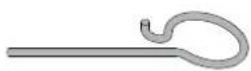


Safety clip 2 units Guide spacer 4 units Set protection cushion 4 units
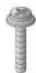
Guide space screw 4 units
(M6 X 43 mm)

IMPORTANT SAFETY INSTRUCTIONS
- If you are a professional installer, please read this manual carefully before installing the product.
- If you are a professional installer, please give this manual to the user after installing the product and ensure that the user also reads the manual carefully and retains it for future reference.
After reading the manual, please keep it handy for future reference.

Warning
The product should be installed by a qualified professional specified by the retail store.
Product installation by non-qualified personnel is very dangerous and may cause personal injury.
The product should be installed where its weight can be fully supported.
If the product is installed on a weak surface, the product may fall, causing injury.
When moving or replacing the product after installation, contact a qualified installer specified by the retail store.
Installation or movement of the product must be carried out by a skilled professional. If an unqualified person moves and installs the product, it may cause safety risks.
Do not hang on this product, protect the product from severe impacts after the installation.
The product may fall and cause injury.
Be sure not to hang the power cable and signal cable on the back of TV when installing the wall-mounted TV.
Damaged cables may result in fire, electric shock, or damage to the product.

Caution
Follow the instructions in this manual to product properly.
If you do not follow these instructions, the product may be installed incorrectly and cause serious injury or the product may become damaged.
When installing the product, first check that the wall is strong enough. Use the anchors and screws provided.
If you use anchors and screws that are not specified by the manufacturer, they may not hold the weight of the product, causing safety issues.
Do not clean the product with a wet towel, and do not place a heater, or humidifier beneath it.
Moisture, steam or heat permeating into this product may result in fire, electric shock or product damage.
Make sure that the power cord is removed from the outlet before installing the product.
Otherwise, it may cause an electric shock or fire.
Be sure to use the accessory cable provided. Otherwise, friction between the product and the wall may cause damage to the connector.
To install or adjust the height of the product, two or more people are needed.
If you try to install or move the product alone, it may fall and cause injury or the product may become damaged.
When drilling holes into the wall, make sure you use a drill and drill bit with the specified diameter. Ensure that you also follow the instructions regarding the depth of the holes.
Otherwise, the product may be installed incorrectly and cause safety issues.
Keep this product away from sprinklers, sensors, high-tension wires and power sources. Do not install it in a location where vibrations or impacts are likely to occur.
Wear safety gloves when installing the product. Do not use your bare hands.
Otherwise, it may cause personal injury.

BEFORE INSTALLATION
* Do not use the product for purposes other than mounting a display on the wall.
* When installing/using the wall mount, be cautious of product damage and avoid accidents.
* Install the wall mount according to the installation manual.
* If you have not fully read and understood the installation manual, do not install the product and contact the dealer to have a specialized installer install the product for you.
* Even if you are not a specialized installer, it is advantageous to have experience in mechanical or construction field in completely understanding this manual and installing the product.
* Install the product only on a vertical wall.
The manufacturer is not responsible for issue from installing the product on an angled wall or on the ceiling.
* Check that the accessories provided with the product are all included before installing. LG Electronics is not liable for any damage or loss of accessories after the package has been opened.
* Keep the included accessories out of reach of babies or children as it can cause safety issues including suffocation from swallowing the parts.
* Make sure screws are tight against the wall, but do not overtighten.
Applying excessive force to screws may damage to the wall, affect the product performance, or cause the product to become damaged.
* Be careful not to install a TV that exceeds the weight restrictions of the wall mount.
* Be careful with the tools used during installation to prevent accidents or damage.
- Tools you will need - Phillips head + driver (manual or motorized) / 8 mm socket wrench / Level / Drill. You may also need an ∅ 8 mm drill bit for concrete.

INSTALLATION
- The picture may differ from the actual product.
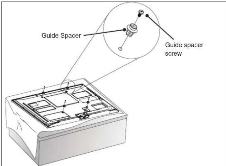
1 How to Attach the Brackets for the Product to the TV
- If the screw will not fully tighten when using a guide spacer, recheck the assembly depth of the screw and refer to the technical service manual.
- Work procedure
- Check to see if the display has screws installed into the mounting holes. If so, remove those.
- Assemble the guide spacer and the guide spacer screw in order as shown in the picture.
— Place the TV on a table with the screen facing down. Make sure that you place it on a flat surface covered with a soft cloth or cushion to protect it from scratches.
- Secure the guide spacers to the TV with the screws. Assemble the guide spacer to the set by tightening the screw. Tighten the screw until the set, guide spacer and the screw are fully pressing against one another.
- Use the + driver (manual or motorized) when tightening the screw.
2 How to attach to masonry walls
Please follow the below direction.
Check the material of the wall and the thickness of the finishing.
- Use the anchors for wall material of concrete, light concrete, strong natural stone, soft natural stone masonry brick and hallow block that do not crack.
- Do not mount the device on the walls made from plasterboard or medium density fiberboard (MDF). In this case, the anchor and screws must be inserted into the concrete behind the finish surface. If there is no concrete on the other side, then you must first install a separate hanger to securely install the anchors and screws.
- When installing the product on wall material not designated, install the product so that each location can withstand the pull out load of 70 kgf (686 N) and shear load of 100 kgf (980 N) or above.
natural_image
Close-up of a twist drill bit with a circular icon labeled 'a' in the corner (no text or symbols on the drill bit itself)
natural_image
Simple geometric diagram with a gray rectangle and a white rectangle, no text or symbols present.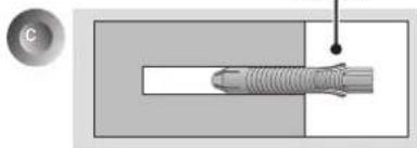
natural_image
Diagram of a threaded screw with a central bore and a pointed tip, shown in two perpendicular panels (no text or labels)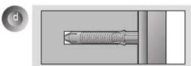
natural_image
Technical diagram of a mechanical component with threaded shaft and flange, shown without any text or symbols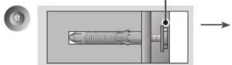
natural_image
Mechanical assembly diagram showing a threaded component inserted into a housing with a valve, alongside a circular inset labeled 'e' (no text or symbols on the diagram itself)
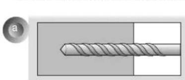
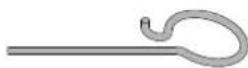
- Use the ∅ 8 mm drill bit for concrete and hammer (Impact) drill.
a. Use a drill bit ∅ 8 mm to drill a hole for the anchor location within a depth of 80 mm to 100 mm.
b. Clean the drilled hole.
c. Insert the sealed anchor to the hole. (When inserting the anchor, use a hammer.)
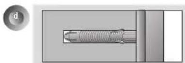
d. Set the wall mount on the wall by aligning to the location of the hole. and, set the angle adjusting part to face upward.
e. Align the wall mount bolt to the hole and tighten it. Then, fasten the bolts at torque of 45 kgf/cm to 60 kgf/cm.
3
How to install the wall mount
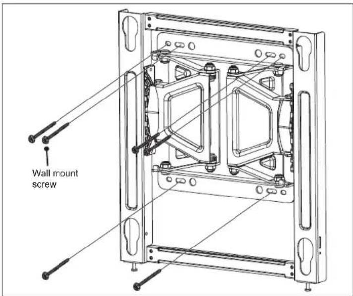
→ If the screw cannot be assembled in the designated location inevitably, it can be assembled by rearranging to the closest location. But, do not change 2 or more locations from the designated spot. → Assemble the wall mount screw on 2 left and 2 right location on the top part and 1 left and 1 right location on the bottom part. → At this time, use a + driver (manual or motorized) or 8 mm wrench to tighten the screw so that the wall, wall bracket and screw are completely pressed against one another.
4
How to assemble the wall mount support and display
- Always install the display with 2 or more people.
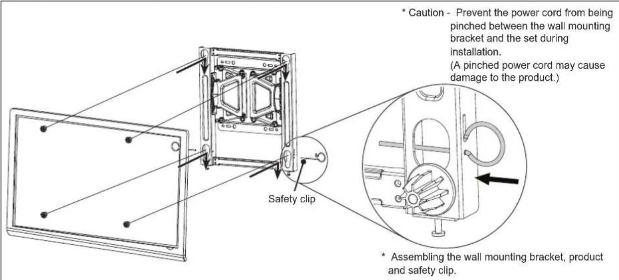
- Set the display with the guide spacer assembled on the wall mount bracket on the wall in arrow direction. At this time, align the bottom assembly part and lift the set up lightly to align the top part.
- When adjusting the location, assemble the provide safety clip as shown in the picture to prevent the product from moving. Tighten the safety clip screw completely. If the safety clip is not tightened as shown in the picture, the product can fall off.
→ Pull on the bottom of the set to make sure the display is secure.
→ When fixing the product with the speaker to the wall, hold and lift up the product, not the speaker.
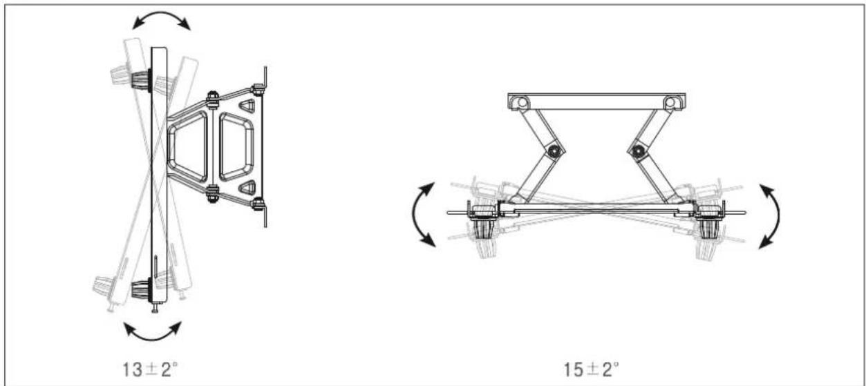
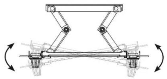
→ When installing a display rotated, only rotate the display 90 degrees (portrait mode). (VESA 300 X 300)
→ Make sure to keep a certain level of distance from the wall so that excessive force is not applied on the cable or accessory.
→ When you push the product with excessive force, the product can be damaged.
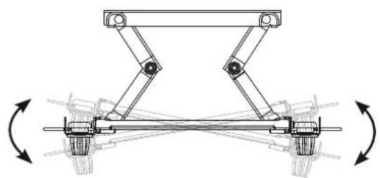
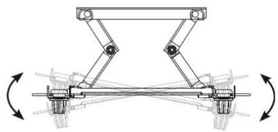
5 How to level the Display
- After installing the display, check to make sure it is level. (The product goes up or down according to the rotation direction of the screw.)
6 How to Organize Cables and Attach Protective Cushions
- Organize the cables as shown in the illustration. Please purchase a band for cable organization, or use the band that comes with the TV/monitor. - Attach the protective cushions to minimize the impact between the wall and the TV in case they bump against each other when adjusting the angle. Attach them in the desired positions, as illustrated.
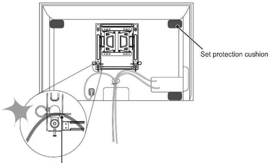
Prevent the power cord and the cables from being pinched between the wall mounting bracket and the wall.

SPECIFICATIONS
The model and serial number of the product is located on the back or one side of the product. Record it below should you ever need service.
MODEL ____
SERIAL
Supported Displays
(Please contract the retailers or refer to the TV owner's manual for applicable models.)
설치설명서
벽걸이 지지대
natural_image
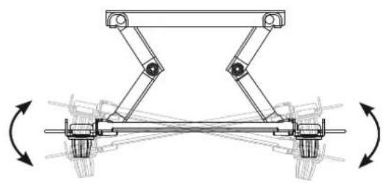
Technical line drawing of a mechanical assembly with rotating components (no text or symbols)13 ± 2^

natural_image
Mechanical linkage diagram showing two vertical arms with rotational arrows indicating motion (no text or symbols)15 ± 2^
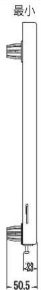
[단위:mm]
natural_image
Technical line drawing of a mechanical assembly with rotating components (no text or symbols)13 ± 2^
natural_image
Mechanical linkage diagram showing two vertical arms with rotational arrows indicating motion (no text or symbols)15 ± 2^
[单位:毫米]

natural_image
Technical line drawing of a mechanical assembly with rotating components (no text or symbols)13 ± 2^
natural_image
Mechanical linkage diagram showing two vertical arms with rotational arrows indicating motion (no text or symbols)15 ± 2^
[Unité : mm]
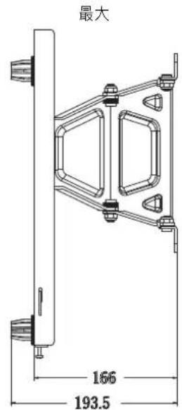
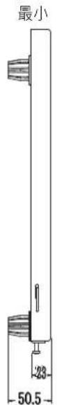
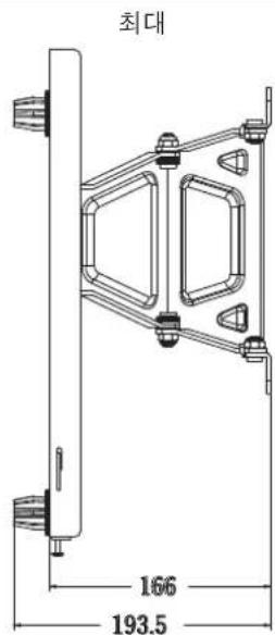
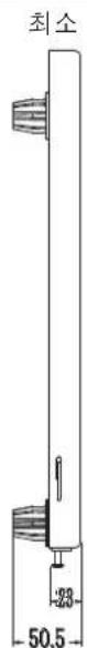
MinimumMaximum

natural_image
Technical line drawing of a vertical cylindrical component with base dimension标注 (no text or symbols)Installationshandbuch
Wandhalterung
Installationshandbuch


natural_image
Close-up of a coiled screw with visible teeth and shaft, shown against a plain background (no text or symbols)
natural_image
Simple diagram with a gray rectangle divided into two sections, one containing a white horizontal bar and the other empty (no text or symbols)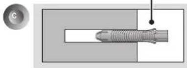
natural_image
Diagram of a threaded screw with a circular head inset showing a hole (no text or labels)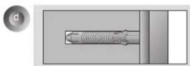
natural_image
Pure mechanical component diagram without any text, numbers, or symbols
natural_image
Mechanical assembly diagram showing a threaded bolt inserted into a housing with a valve, no text or symbols present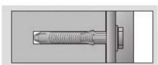
natural_image
Technical diagram of a mechanical component with threaded shaft and mounting bracket (no text or symbols)natural_image
Mechanical assembly diagram showing a vertical rod connected to a bracket with rotating arrows indicating rotation (no text or symbols)13 ± 2^
natural_image
Mechanical linkage diagram showing two vertical arms connected to a horizontal shaft, with rotational arrows indicating motion (no text or symbols)15 ± 2^
[Einheit: mm]
DEUTSCH.
MinimumMaximum

natural_image
Technical line drawing of a vertical cylindrical component with a 50.5mm dimension label (no text or symbols beyond measurement)natural_image
Technical line drawing of a mechanical assembly with rotating components (no text or symbols)13 ± 2^
natural_image
Mechanical linkage diagram showing two vertical arms with rotational arrows indicating motion (no text or symbols)15 ± 2^
[Unità: mm]


MinimoMax

natural_image
Technical line drawing of a vertical cylindrical component with a 50.5mm dimension label (no text or symbols beyond measurement)ITALIANO
natural_image
Close-up of a threaded screw with a circular inset showing a labeled section (a), no text or symbols present.
natural_image
Simple diagram with a gray rectangle and a white rectangle, no text or symbols present.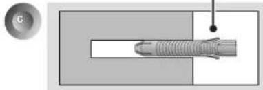
natural_image
Diagram of a mechanical component with threaded end and mounting hole, shown in cross-section (no text or symbols)壁掛け用ネジ
natural_image
Mechanical component diagram showing a threaded bolt inserted into a housing (no text or symbols)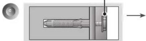
natural_image
Mechanical assembly diagram showing a threaded component inserted into a housing with an arrow indicating direction (no text or labels)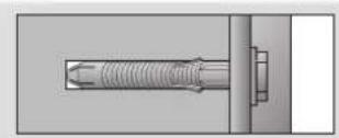
natural_image
Technical illustration of a threaded fastener assembly (no text or symbols visible)natural_image
Technical line drawing of a mechanical assembly with rotating components (no text or symbols)13 ± 2^

natural_image
Mechanical linkage diagram showing two vertical arms with rotational arrows indicating motion (no text or symbols)15 ± 2^
[单位:mm]


2 Como instalar as buchas e os parafusos
Siga as instruções.
natural_image
Technical line drawing of a mechanical assembly with rotating components (no text or symbols)13 ± 2^

natural_image
Mechanical linkage diagram showing two vertical arms with rotational arrows indicating motion (no text or symbols)natural_image
Technical line drawing of a vertical cylindrical component with a 50.5mm dimension label (no text or symbols beyond measurement)PORTUGUÊS
natural_image
Close-up of a threaded screw with a circular inset showing a labeled section 'a' (no text or symbols on the screw itself)
natural_image
Simple diagram with a gray rectangle and a white rectangle, no text or symbols present.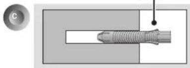
natural_image
Diagram of a threaded component with a circular inset showing a magnified view (no text or symbols)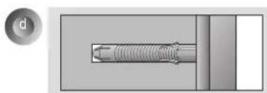
natural_image
Pure mechanical component diagram without any text, numbers, or symbols
natural_image
Mechanical assembly diagram showing a threaded component inserted into a housing with a bolt, alongside a circular button labeled 'e' (no text or symbols on the diagram itself)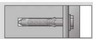
natural_image
Technical illustration of a threaded fastener assembly with mounting bracket (no text or symbols)natural_image
Technical line drawing of a mechanical assembly with rotating components (no text or symbols)13±2°

natural_image
Mechanical linkage diagram showing two vertical arms connected to a horizontal shaft, with rotational arrows indicating motion (no text or symbols)natural_image
Close-up of a twisted screw with a circular inset showing a labeled section (a), no text or symbols present.
natural_image
Simple diagram with a gray rectangle and a white rectangle, no text or symbols present.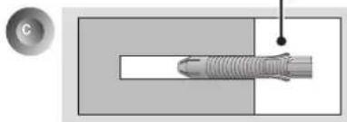
natural_image
Diagram of a threaded rod inserted into a rectangular block, with a magnified inset showing the tip (no text or symbols)natural_image
Mechanical component diagram showing a threaded bolt inserted into a housing (no text or symbols)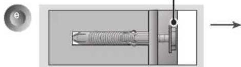
natural_image
Mechanical assembly diagram showing a threaded component inserted into a housing with a bolt, no text or symbols present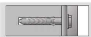
natural_image
Technical illustration of a mechanical assembly with threaded component and mounting bracket (no text or symbols)natural_image
Technical line drawing of a mechanical assembly with rotating components (no text or symbols)13±2°

natural_image
Mechanical linkage diagram showing two vertical arms with rotational arrows indicating motion (no text or symbols)15 ± 2^
[Unidad: mm]

Mínimo Máximo
natural_image
Technical line drawing of a mechanical assembly with rotating components (no text or symbols)13 ± 2^
natural_image
Mechanical linkage diagram showing two vertical arms with rotational arrows indicating motion (no text or symbols)15 ± 2^
[單位:公釐]