
ABVP200X - TV Mount LG - Free user manual and instructions
Find the device manual for free ABVP200X LG in PDF.
| Product type | MultiVision mounting frame for TVs |
| Brand | LG |
| Model | ABVP200X |
| Compatibility | LG monitors in landscape or portrait configuration |
| Dimensions (W x H x D) | 1426 x 210 x 1006 mm |
| Net weight | 22.6 kg (AB-VL200X) / 22 kg (AB-VP200X) |
| Material | Metal (steel or aluminum, unspecified) |
| Maximum load | Unspecified, but must support the weight of installed monitors |
| Mounting type | Vertical wall mount (concrete or stud wall) |
| Power supply | None (passive support) |
| Main functions | Mounting multiple monitors in a matrix, adjustable horizontal and vertical alignment |
| Included accessories | 4 spacing guides, 4 M8x32 mm screws, 3 M8x100 mm screws, 3 nuts, wrench, user manual |
| Installation | By qualified installer recommended; requires drill, Phillips screwdriver, 8 mm wrench, level |
| Maintenance and cleaning | Clean with a soft dry cloth; do not use a damp cloth |
| Safety | Do not hang on the product, respect ventilation distances (20 cm sides, 15 cm rear), disconnect power before installation |
| Spare parts and repairability | Screws and nuts are provided; contact LG service center for replacement parts |
| General information | Manual included; model also known as AB-VL200X (landscape) and AB-VP200X (portrait) |
Frequently Asked Questions - ABVP200X LG
User questions about ABVP200X LG
0 question about this device. Answer the ones you know or ask your own.
Ask a new question about this device
Download the instructions for your TV Mount in PDF format for free! Find your manual ABVP200X - LG and take your electronic device back in hand. On this page are published all the documents necessary for the use of your device. ABVP200X by LG.
USER MANUAL ABVP200X LG
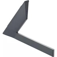
MultiVision Mounting Bracket
Please read the safety information carefully before using the product.
AB-VL200X
AB-VP200X

MultiVision Mounting Bracket


MultiVision Mounting Bracket-Portrait AB-VP200X

MultiVision Mounting Bracket-Landscape AB-VL200X
Accessories

4 Guide Spacer

4 Guide Spacer Fixing Screws (M8X32mm)

3 Bracket Fixing Screws (M8X100mm)

3 Nuts

Owner's Manual

Wrench

Safety Precautions

- If you are a professional installer, please read this manual carefully before installing the product.
- After installing the product according to the manual, ensure that the user also reads the manual carefully.
After reading the manual, please keep it handy for future reference.

Warning
The product should be installed by a qualified professional specified by the retail store.
Installing the product without a qualified professional is dangerous and may cause injury.
The product should be installed where its weight can be supported.
If the product is installed on a weak surface, the product may fall and cause injury.
When moving or replacing the product after installation, contact a qualified installer specified by the retail store.
Installation or movement of the product must be carried out by a skilled professional. If an unqualified person moves and installs the product, this may cause safety issues.
Do not hang on the product or apply shock to the product.
The product may fall and cause injury.
Prior to installing the product, arrange the power cable and signal cable to prevent damage during installation.
Damaged cables may result in a fire, electric shock or damage to the product.

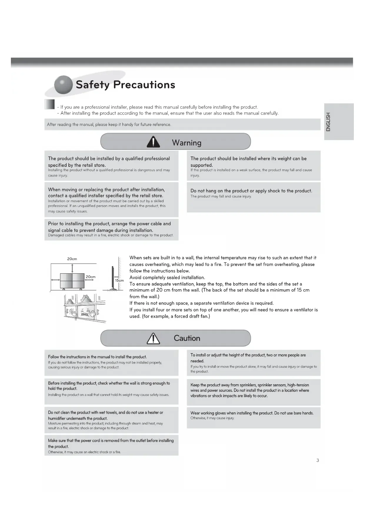
When sets are built in to a wall, the internal temperature may rise to such an extent that it causes overheating, which may lead to a fire. To prevent the set from overheating, please follow the instructions below.
Avoid completely sealed installation.
To ensure adequate ventilation, keep the top, the bottom and the sides of the set a minimum of 20cm from the wall. (The back of the set should be a minimum of 15cm from the wall.)
If there is not enough space, a separate ventilation device is required.
If you install four or more sets on top of one another, you will need to ensure a ventilator is used. (for example, a forced draft fan.)

Caution
Follow the instructions in the manual to install the product.
If you do not follow the instructions, the product may not be installed properly, causing serious injury or damage to the product.
To install or adjust the height of the product, two or more people are needed.
If you try to install or move the product alone, it may fall and cause injury or damage to the product.
Before installing the product, check whether the wall is strong enough to hold the product.
Installing the product on a wall that cannot hold its weight may cause safety issues.
Keep the product away from sprinklers, sprinkler sensors, high-tension wires and power sources. Do not install the product in a location where vibrations or shock impacts are likely to occur.
Do not clean the product with wet towels, and do not use a heater or humidifier underneath the product.
Moisture permeating into the product, including through steam and heat, may result in a fire, electric shock or damage to the product.
Wear working gloves when installing the product. Do not use bare hands.
Otherwise, it may cause injury.
Make sure that the power cord is removed from the outlet before installing the product.
Otherwise, it may cause an electric shock or a fire.

Transportation method for panel protection
When moving or lifting the monitor, read the following to prevent the monitor from being scratched or damaged and for safe transportation regardless of its type and size.

CAUTION
- Avoid touching the screen at all times, as this may result in damage on the screen.
It is recommended to move the monitor in the box or packing Cover that the monitor originally came in.
- Before moving or lifting the monitor, disconnect the power cord and all cables.
- Hold the top and bottom of the monitor frame firmly. Make sure not to hold the transparent part, speaker, or speaker grill area.

- When transporting the monitor, do not expose the monitor to jolts or excessive vibration.
- When transporting the monitor, keep the monitor upright, never turn the monitor on its side or tilt towards the left or right.
- When transporting the monitor by hand, hold the monitor as shown in the following illustration.
- When the product is carried upright, 2 persons carry by holding the bottom and top of the front, and when it is being put down, put down carefully for the panel not to be touched.

- When the product is carried laid down, 2 persons carry by holding the bottom of the back, and when it is being put down, put down carefully for the panel not to be touched.


Storage method for panel protection

If the product needs to be set upright, hold both sides of the product, and tilt backward carefully for the panel not to touch the floor. (The setting upright of the set is possible with the outer frame)
When laying down the product, lay a cushion on a flat floor, and put the product on it with the panel of the product facing down.

If the product is tilted to the side of the panel, the bottom of the panel may be damaged.
If the product is tilted to the edge of the panel, the edge of the panel may be damaged.

NOTE
- Handle the product with care. The product may be damaged by shocks.
The illustration depicts a landscape installation, but the procedure is identical to that of a portrait installation.)

Before Installation
- Do not use this product for purposes other than to attach the monitor to the wall.
- Be careful when installing and using the bracket to prevent product damage and safety hazards.
* If the instructions in the manual are unclear, stop the installation and contact the service center. If you are still having problems understanding the instructions after contacting the center, seek a professional to install the product. - An individual with experience in mechanical and architectural fields may not have any difficulty understanding this manual or installing the product, even if they are not a professional.
- When installing the bracket on a concrete wall or on any other walls capable of holding the strength specified in the manual, you may detach the standard gap bracket for stud wall mounting then follow the instructions for attaching the bracket to make the installation easier.
* Only install the bracket on vertical walls. Do not install the bracket on a wall inclined at an angle, exceeding the standard range or on the ceiling. LG Electronics is not liable for problems that occur due to the installation of the product on a slanted wall or on the ceiling. - Check the accessories provided with the product before installing. LG Electronics is not liable for any damage to or loss of the accessories after the package has been opened.
- Make sure that the accessories are kept out of reach of children to prevent safety accidents, such as choking due to swallowing small parts.
- Make sure that the screws are fixed tightly. Applying excessive force to screws may impair the performance or reduce the strength of the product, or cause it to become damaged.
- Make sure that the monitor to be installed does not exceed the specified tension load and that no external force is applied.
- In order to prevent accidents, take care when handling tools during installation of the product.
Philips screwdriver (manual or electric)/8 mm spanner/drill/level meter

How to Install

Assembling the MultiVision Bracket
Attach the brackets using two bracket fixing screws (M8 x 100 mm) and nuts. The procedure is based on 2X2 installation.


CAUTION
- Check the direction of the arrows shown in the figure above to avoid placing the bracket upside down.
2
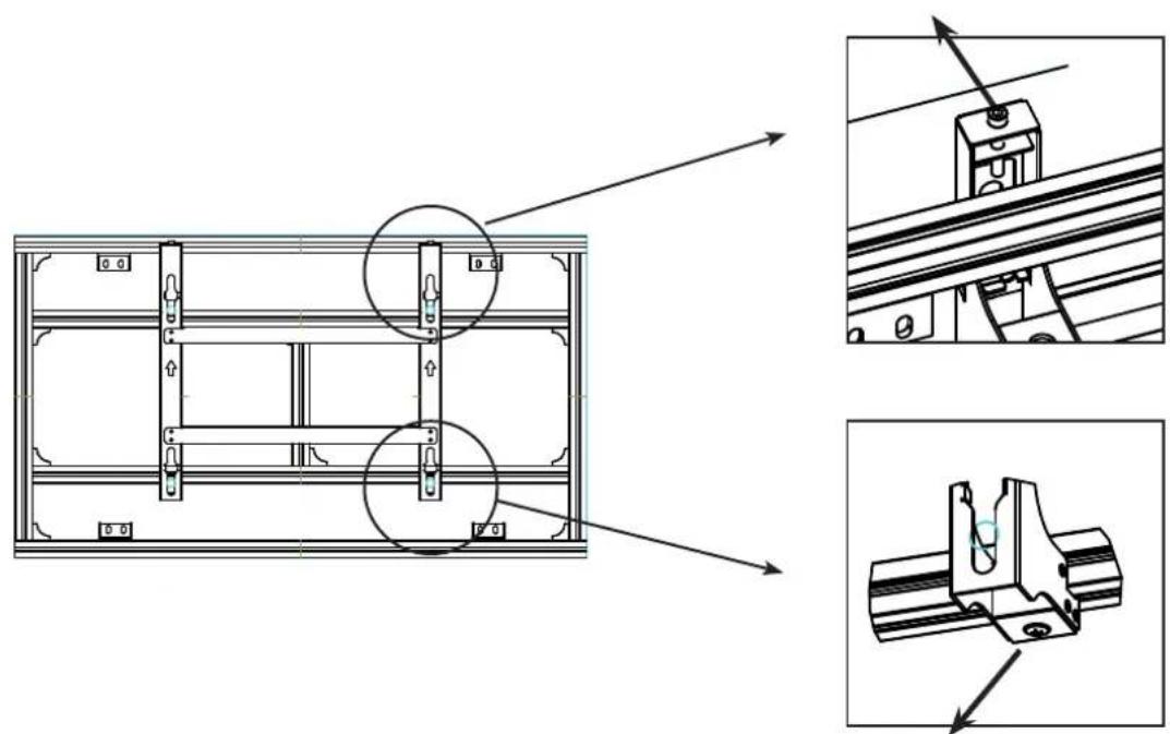
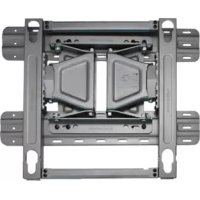
Verifying Where the Brackets Are Fixed
Refer to the following illustration to fix the brackets according to the type.


MultiVision Wall Bracket-Portrait AB-VP200X
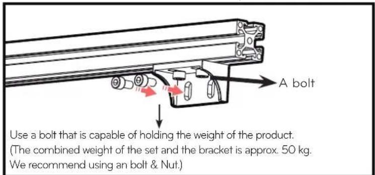
The bracket may be distorted, depending on the flatness of the wall. Adjust the flatness of the bracket using the A bolts attached to it.
3
Attaching the Guide Spacers
If the screws are not fully tightened when you fix the guide spacers, check the length of the screws and refer to the technical service manual.

Fix the guide spacers and the guide spacer fixing screws in the order shown in the picture.
Lay the set down and fix the guide spacers to the set using the screws.
-
Place the product on a table with its screen facing downward. Make sure that you place it on soft clothing or a cushion on the flat surface to protect the screen.
-
Tighten the screw until the set, the guide spacer and the screw are joined together securely.
- Use a Philips driver (manual or electric) to tighten the screws.
4
Dip switch setting

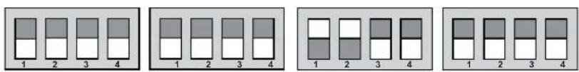
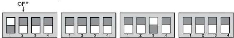
Factory reset
monitor #1

monitor #5
5
How to Attach the Product and Bracket
- Two or more people are needed to install the product.
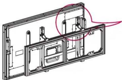

Place the product assembled with the guide spacers, as illustrated with the arrow.
- Make sure that the product is fixed securely by checking attachment.
6
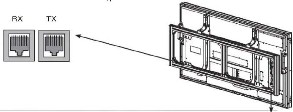
Connecting Cables
- It is recommended to arrange cables using the bracket first to install the set.
- For information on how to connect cables, please refer to the set's owner's manual.


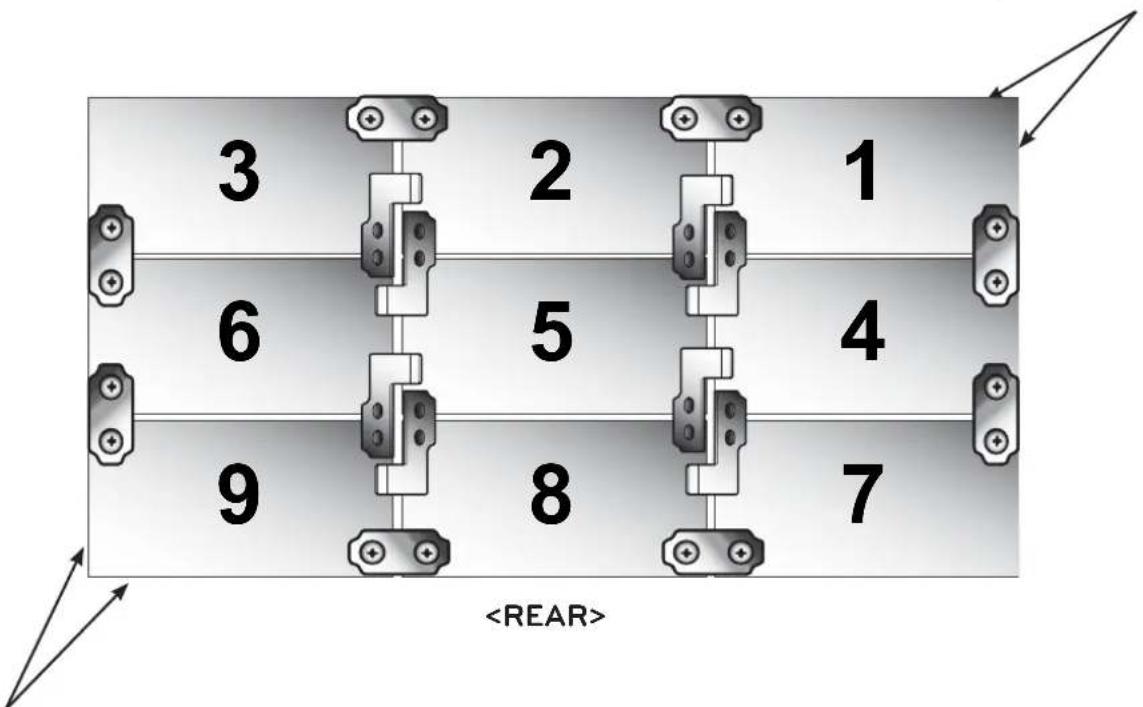
Set Arrangement
The procedure is based on 3X3 installation.
Set Arrangement step: 8 5 2, 7 4 1, 9 6 3
| 3 | 2 | 1 |
| 6 | 5 | 4 |
| 9 | 8 | 7 |
- Mount set 8, then loosen the horizontal alignment screws to lower the set by approximately 30mm
(Caution: Otherwise, when set 5 is mounted the sets may collide and cause damage.)
Once the set is lowered, use the horizontal alignment screws to align the set horizontally. Tighten the right/left screws.
Loosen the screw to lower the set.
(Loosen the right and left screws gently in turn.)
Tighten the screws to fix the left and right slides.
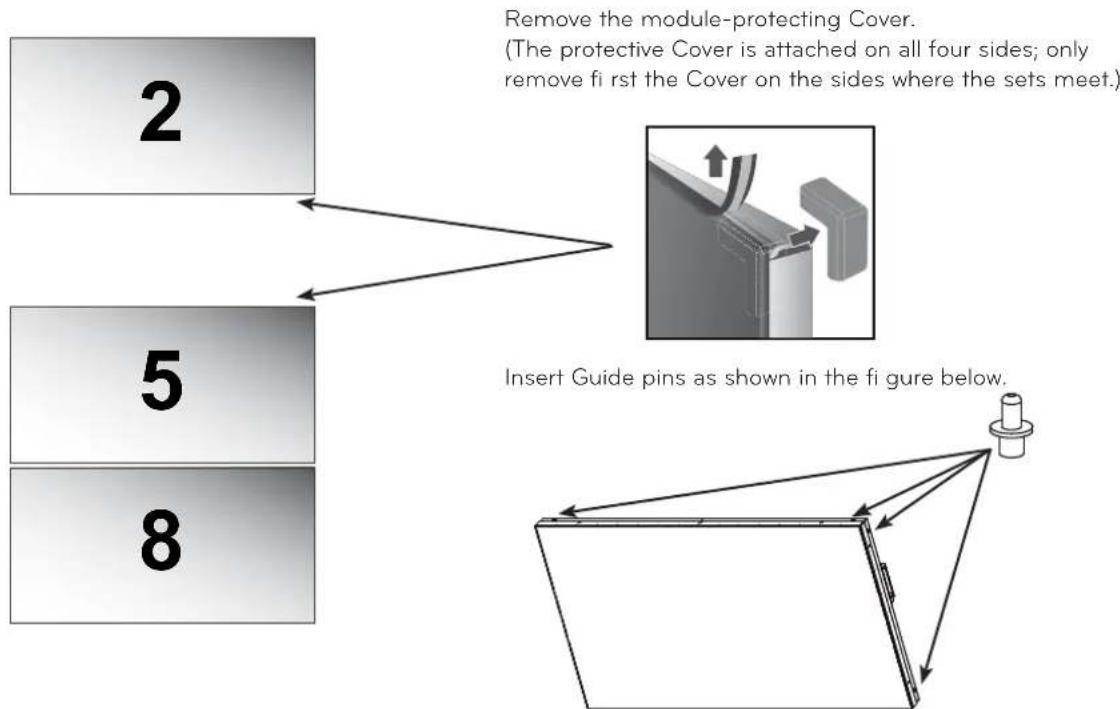
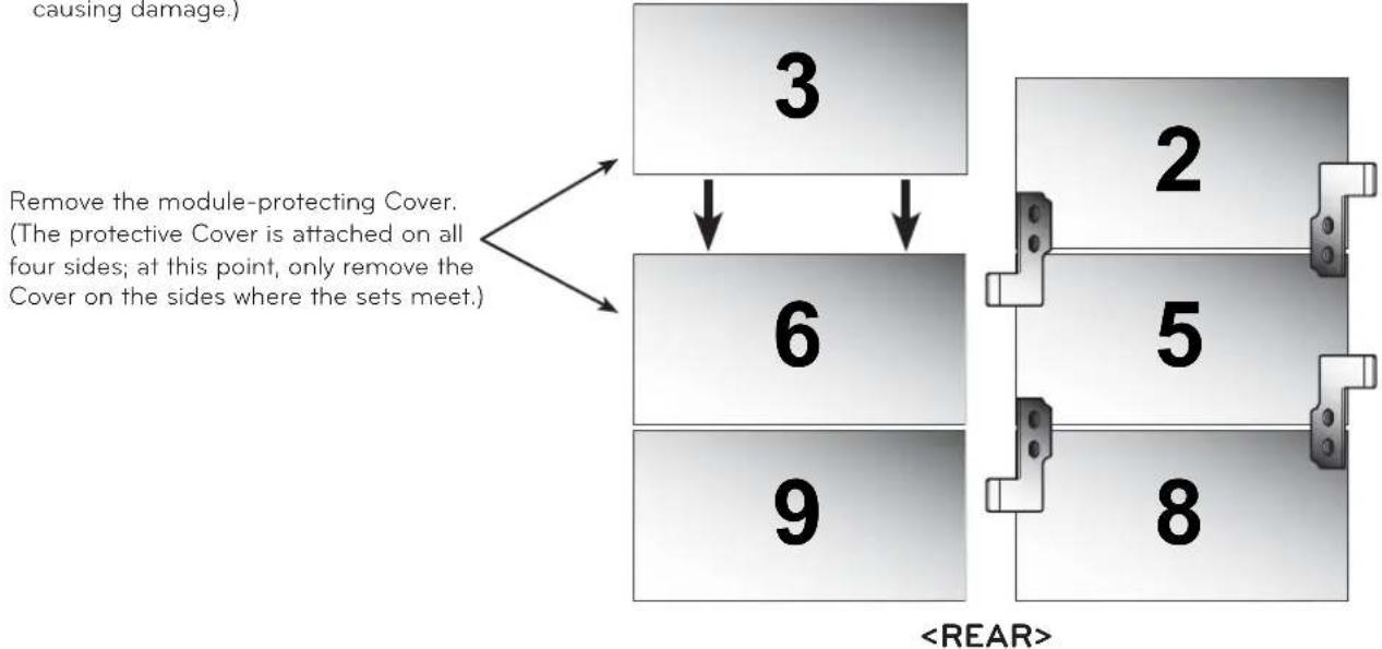
- Mount set 5, then remove the module-protecting Cover on sets 8 and 5.
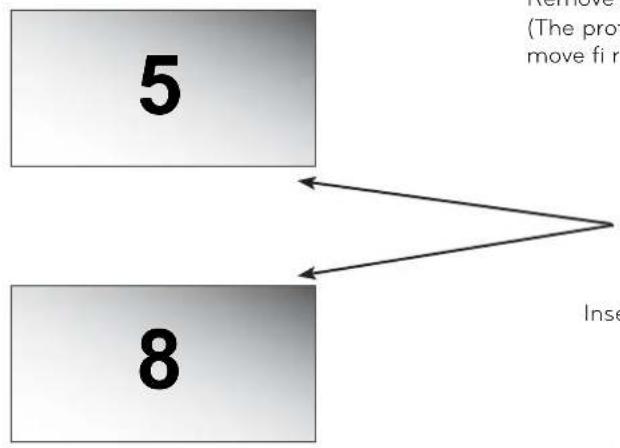
Remove the module-protecting Cover. (The protective Cover is attached on all four sides; only remove first the Cover on the sides where the sets meet.)

Insert Guide pins as shown in the figure below.

- Loosen the horizontal alignment screws on bracket 5, then attach set 5 to set 8. (Caution: Loosen the right and left horizontal alignment screws gently in turn to prevent the set from tilting and causing damage.) Fasten the right and left slides of set 5 using the right/left fixing screws.


CAUTION
-
Loosen the left and right leveling screws slowly in turns. Otherwise, this may make the set tilted, which may cause damage to the set.
-
Mount set 2 in the same way as set 5 is mounted.
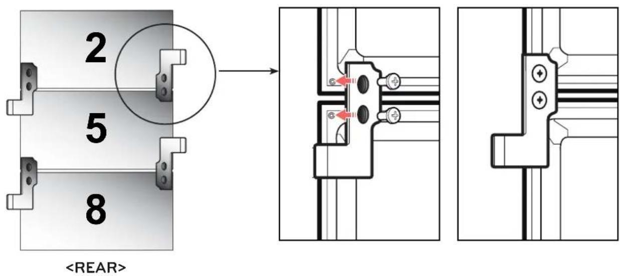
- Mount set 2, then remove the module-protecting Cover attached between set 5 and 2.
- Loosen the horizontal alignment screws on bracket 2, then attach set 2 to set 5.
(Caution: Loosen the right and left horizontal alignment screws gently in turn to prevent the set from tilting and causing damage.)
Fix the right and left slides of set 2 using the right/left fixing screws.

Loosen the screw to lower the set.
(Loosen the right and left screws gently in turn.)

Tighten the screws to fix the left and right slides.
- Use the guide fixers provided to attach sets 2, 5 and 8 as shown below and align them side by side so that no set sticks out at the front or back.
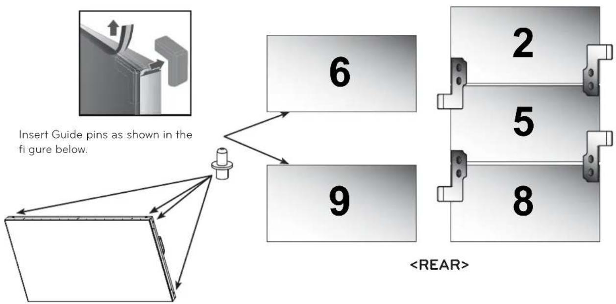
- Mount set 9 then adjust its height using the horizontal alignment screws so that set 9 and set 8 are at the same height.
(Caution: Before mounting the set, push bracket 7 to the left end to ensure there is enough space for set 8.)

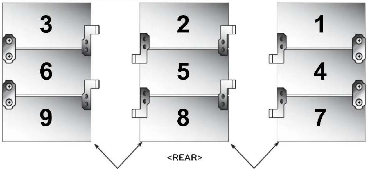
- Mount set 6, then remove the module-protecting Cover from sets 9 and 6.
Remove the module-protecting Cover.
(The protective Cover is attached on all four sides; only remove first the Cover on the sides where the sets meet.)
ENGLISH
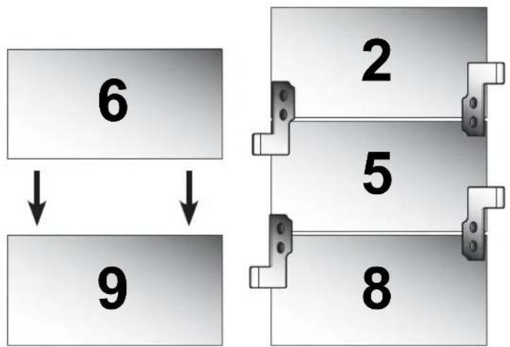
- Loosen the horizontal alignment screws on bracket 6, then attach set 6 to set 9.
(Caution: Loosen the right and left horizontal alignment screws gently in turn to prevent the set from tilting and causing damage.)
- Mount set 3, then remove the module-protecting Cover in the same way.
Loosen the horizontal alignment screws on bracket 3, then attach set 3 to set 6.
(Caution: Loosen the right and left horizontal alignment screws gently in turn to prevent the set from tilting and causing damage.)
- Use the guide fixers provided to attach sets 3, 6 and 9 as shown below so that the sets are aligned in a perfectly straight line.

- Mount sets 1, 4 and 7 in the same way as sets 3, 6 and 9 are mounted.
- Sets 2, 5 and 8 are fixed with the right/left fixing screws; sets 1, 4 and 7 and 3, 6 and 9 are not fixed with the right/ left fi xing screws and can slide to the right or left.
- Remove the module-protecting Cover before aligning the sets.
ENGLISH
Remove the module-protecting Cover. Remove the module-protecting Cover.
- Push sets 3, 6 and 9 to the right to meet sets 2, 5 and 8.
Similarly, push sets 1, 4 and 7 to the left to meet sets 2, 5 and 8.
(Caution: Push gently and slowly to avoid damage due to a collision.) - Once the sets meet, tighten the right and left fixing screws for sets 1, 4 and 7 and sets 3, 6 and 9 to prevent them from sliding.

- Attach additional fixers to the marked areas to make sure that sets do not stick out at the front or back.
- Finally, remove all the module-protecting Cover on the outside of the sets.
Remove the module-protecting Cover.
Remove the module-protecting Cover.


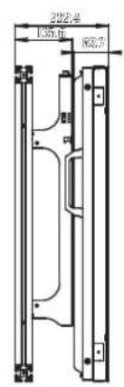

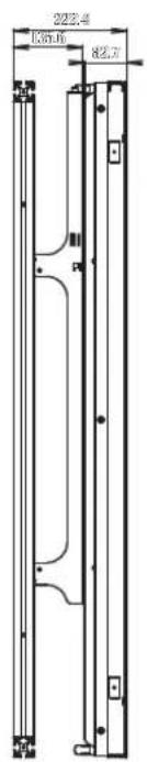
| Model Name | AB-VL200X AB-VP200X |
| Width (mm) 1426 1426 | |
| Height (mm) 210 210 | |
| Depth (mm) 1006 1006 | |
| Weight (kg) 22.6 22 |
The model name and serial number are located on the back and side of the product.
Please make a note of these below.
Model Name
Serial Number

- MultiVision Mounting Bracket
- Accessories
- Safety Precautions
- Warning
- Caution
- Transportation method for panel protection
- Storage method for panel protection
- NOTE
- Before Installation
- How to Install
- Assembling the MultiVision Bracket
- 2
- Verifying Where the Brackets Are Fixed
- 3
- Attaching the Guide Spacers
- Dip switch setting
- How to Attach the Product and Bracket
- Connecting Cables
- Set Arrangement
Brand : LG
Model : ABVP200X
Category : TV Mount