DKE985S - Basket BOSCH - Free user manual and instructions
Find the device manual for free DKE985S BOSCH in PDF.

User questions about DKE985S BOSCH
0 question about this device. Answer the ones you know or ask your own.
Ask a new question about this device
Download the instructions for your Basket in PDF format for free! Find your manual DKE985S - BOSCH and take your electronic device back in hand. On this page are published all the documents necessary for the use of your device. DKE985S by BOSCH.
USER MANUAL DKE985S BOSCH
natural_image
Black-and-white photo of a hand holding a plate of cooked rice with a small bowl and chili (no text or symbols visible)DKE 985 S
natural_image
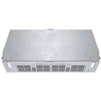
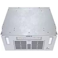
Exterior view of a stainless steel kitchen range hood (no text or symbols visible)de Gebrauchs- und
Montageanweisung
en Operating and
installation instructions
fr Mode d'emploi et
notice de montage
Household Appliances
de Seite 3–17
en page 18 - 32
fr pages 33 - 47
nl pagina 48 – 62
it pagina 63 – 77
es página 78 - 92
pt página 93 - 107
SV sid 108 - 122
no side 123 - 137
fi Sivu 138 - 152
da side 153 - 167
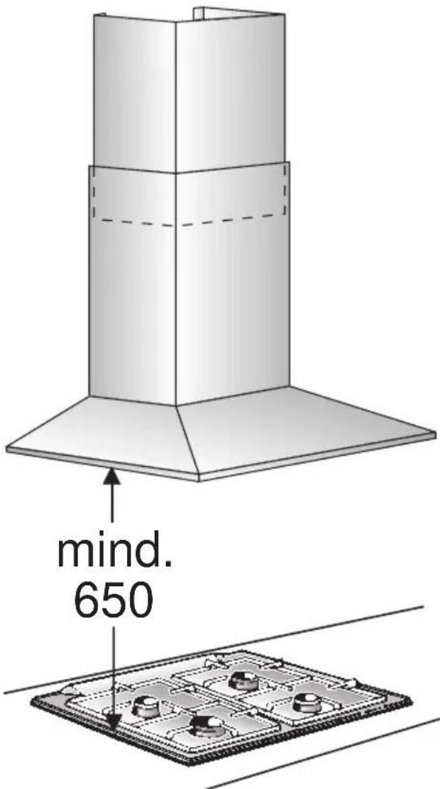
Abb. 1
GAS
GAZ
KAASU
GASS
ELEKTRO
ELECTR.
ELETT.
EL.
text_image
mind. 650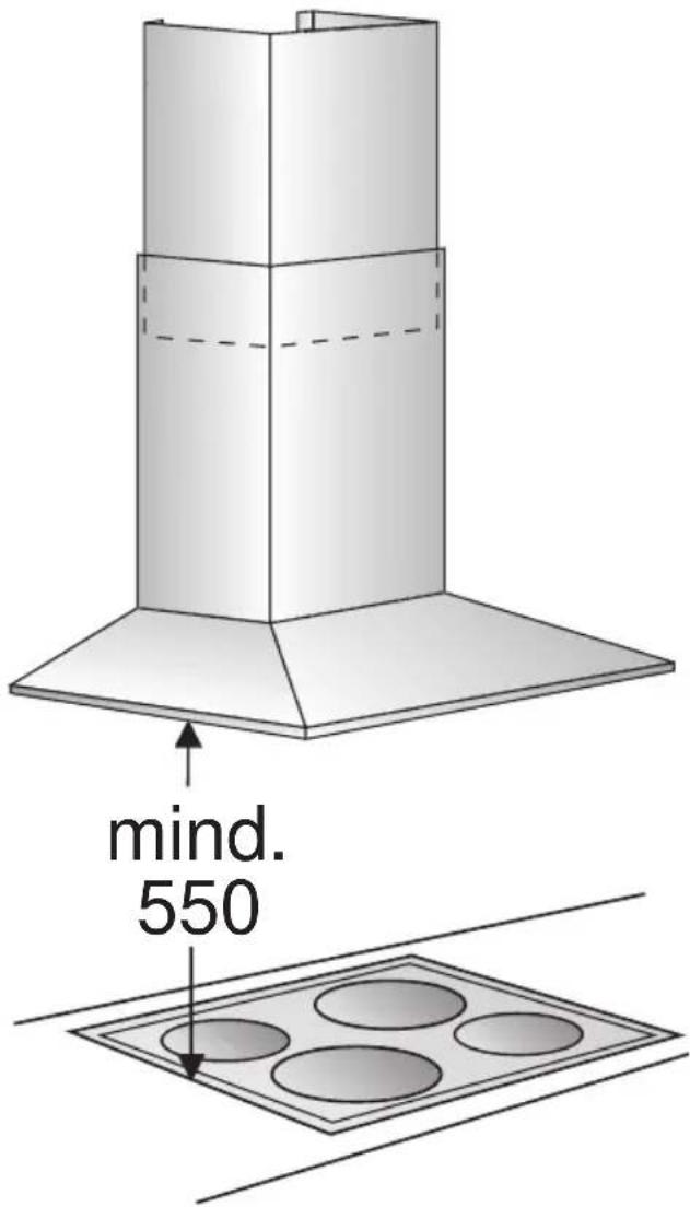
text_image
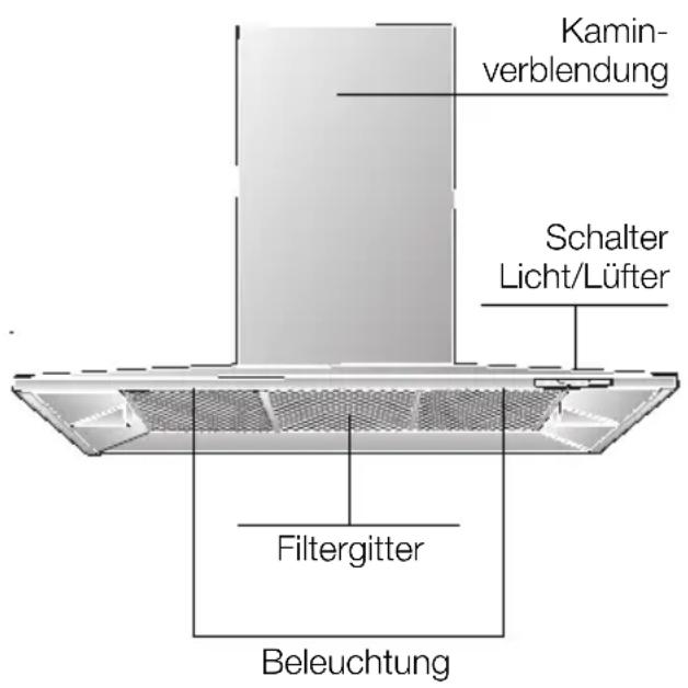
mind. 550Gerätebeschreibung
text_image
Hand-drawn interface with icons for addition, summing, rotation, and navigation controlsLüfterstufen:
text_image
Diagram showing a finger pointing to a numeric keypad with plus, minus, and angle indicators, alongside a stylized 'A' symbol.text_image
A ○ ← ● 灯Sonderfunktionen
text_image
Diagram showing three labeled objects with symbols and dashed lines, possibly illustrating a conceptual or mechanical concept.text_image
- B + o A o G =natural_image
Diagram showing three views of a device with mesh patterns and a magnified inset highlighting a specific area (no text or symbols present)natural_image
Illustration of a hand holding a shelf with a tray, no text or symbols presentnatural_image
Illustration of a hand inserting a Y-shaped tool into a metal panel (no text or symbols)natural_image
Illustration of a magnifying glass with a handle and circular lens (no text or symbols)natural_image
Illustration of a hand holding a device with a curved arrow pointing to a circular component (no text or symbols)natural_image
Diagram of airflow or heat transfer between a building interior and adjacent wall, showing directional arrows (no text or symbols)natural_image
Technical illustration of a mechanical assembly with labeled components (no text or symbols present)text_image
Technical diagram illustrating assembly steps of a mechanical assembly with labeled components and numbered instructions.text_image
Diagram illustrating a mechanical or electrical component with directional arrows and a magnified inset showing internal components.☐ The extractor-hood fan extracts the kitchen vapours and conveys them through the grease filter into the atmosphere.
☐ The grease filter absorbs the solid particles in the kitchen vapours.
☐ The kitchen is kept almost free of grease and odours.
When the extractor hood is operated in exhaust-air mode simultaneously with a different burner which also makes use of the same chimney (such as gas, oil or coal-fired heaters, continuous-flow heaters, hot-water boilers) care must be taken to ensure that there is an adequate supply of fresh air which will be needed by the burner for combustion.
Safe operation is possible provided that the underpressure in the room where the burner is installed does not exceed 4 Pa (0.04 mbar).
Operating modes
This can be achieved if combustion air can flow through non-lockable openings, e.g. in doors, windows and via the air-intake/exhaust-air wall box or by other technical measures, such as reciprocal interlocking, etc.
If the air intake is inadequate, there is a risk of poisoning from combustion gases which are drawn back into the room.
An air-intake/exhaust-air wall box by itself is no guarantee that the limiting value will not be exceeded.
Note: When assessing the overall requirement, the combined ventilation system for the entire household must be taken into consideration. This rule does not apply to the use of cooking appliances, such as hobs and ovens.
Unrestricted operation is possible if the extractor hood is used in recirculating mode – with activated carbon filter.
Circulating-air mode:
☐ An activated carbon filter must be fitted for this operating mode (see Filters and maintenance).
⚠️ The complete installation set and replacement filters can be obtained from specialist outlets. The corresponding accessory numbers can be found at the end of these operating instructions.
☐ The extractor-hood fan extracts the kitchen vapours which are purified in the grease filter and activated carbon filter and then conveyed back into the kitchen.
☐ The grease filter absorbs the grease particles in the kitchen vapours.
☐ The activated carbon filter binds the odorous substances.
Before using for the first time
Important notes:
☐ The Instructions for Use apply to several versions of this appliance. Accordingly, you may find descriptions of individual features that do not apply to your specific appliance.
☐ This extractor hood complies with all relevant safety regulations.
Repairs should only be carried out by qualified specialists.
Improperly executed repairs can give rise to significant hazards for the user.
☐ Before using your new appliance, please read these Instructions for Use carefully. They contain important information concerning your personal safety as well as on use and care of the appliance.
☐ Please keep the operating and installation instructions in a safe place; this important documentation may also be of use to a possible subsequent owner.
⚠ Do not use the appliance if it is damaged in any way
⚠ The appliance is not intended for use by young children or infirmed persons without supervision.
Young children should be supervised to ensure they do not play with the appliance.
⚠ The appliance should only be connected up to the mains and taken into use by a qualified specialist.
⚠ Dispose of packaging materials properly (see Installation instructions).
Light bulbs must always be fitted when the extractor hood is in use.
⚠️ Defective bulbs should be replaced immediately to prevent the remaining bulbs from overloading.
⚠️ Never operate the extractor hood without a grease filter.
Overheated fat or oil can easily catch fire.
If you are cooking with fat or oil, e.g. chips, etc., never leave the cooker unattended.
⚠ Do not flambé food directly under the extractor hood.
! Risk of grease filter catching fire due to flames.
⚠️ Restrictions apply to the use of the extractor hood over a solid-fuel burner (coal, wood, etc.). (See Installation instructions).
Gas hobs / gas cookers
⚠️ Always use gas hobs in a proper and safe manner.
Important:
The flames from the gas hob must always be covered by pots or pans.
The intense heat generated by the gas flames could cause damage to the extractor hood.
Operating procedure
The most effective method of removing kitchen fumes is to:
□ switch on the extractor hood when you start cooking.
□ switch off the extractor hood a few minutes after you finishing cooking.
☐ The fans in this appliance can be switched to the desired setting by hand (manual mode) or can be controlled fully automatically with the automatic function according to your requirements (automatic mode).
text_image
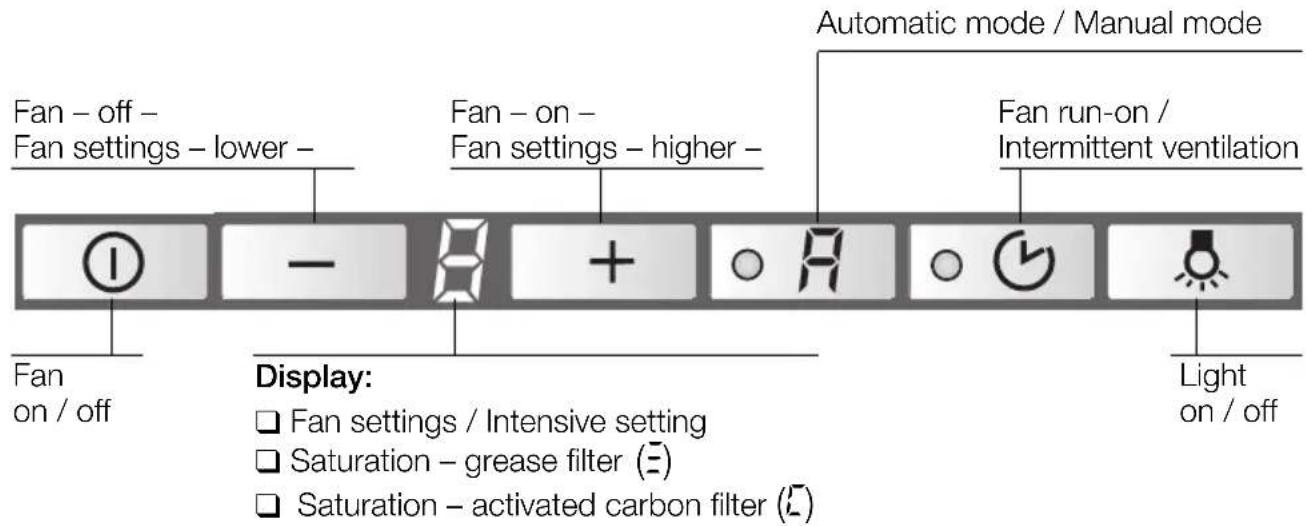
Fan - off - Fan settings - lower - Fan - on - Fan settings - higher - Automatic mode / Manual mode Fan run-on / Intermittent ventilation Fan on / off Display: □ Fan settings / Intensive setting □ Saturation - grease filter (E) □ Saturation - activated carbon filter (C) Light on / offSwitching on manual mode:
Press the Ⓐ or + button.
☐ The fan starts at Setting 2.
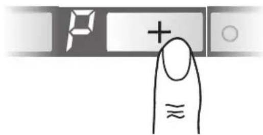
Switching on the fan settings/intensive setting:
- To increase the fan settings or switch on the intensive setting P, press the + button.
☐ The intensive setting operates at maximum power which should be used only briefly. If the intensive setting is not switched off manually, the fan automatically switches back to Setting after 10 minutes.
- To switch off the intensive setting P or switch back to fan settings 3 - 2 - and switch off the extractor hood completely, press the - button.
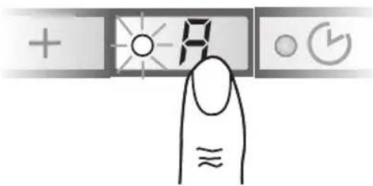
Switching over to automatic mode:
☐ To switch from manual mode to automatic mode at any time, press the R button.
Operating procedure
Switching on automatic mode:
Press the R button.
☐ The fan runs at least at Setting ^1 .
text_image
+ + # ○ (✓) ≈ ≈Fan settings:
☐ If required, the optimum fan setting is actuated automatically via a sensor.
☐ The automatic function operates at Settings 1 - 3.
Intensive setting:
- To switch on the intensive setting P, press the + button.
text_image
P + ≈☐ Automatic mode has been switched off.
☐ The intensive setting operates at maximum power which should be used only briefly.
If the intensive setting is not switched off manually, the fan automatically switches back to the optimum fan setting after 10 minutes.
- To switch off the intensive setting, press the - button.
☐ Automatic mode has been switched on again.
Switching over to manual mode:
☐ To switch from automatic mode to manual mode at any time, press the 🔒 button.
Intermittent ventilation
☐ Used for ventilating the kitchen at hourly intervals at the lowest fan setting, round the clock.
Switching on:
☐ Before intermittent ventilation can be switched on, the appliance must be switched off.
Press the ○ 📋 button.
text_image
+ o R ≈☐ The fan runs for 5 minutes at Setting 1, then switches off for 55 minutes. This process is repeated every hour.
Switching off:
Press the ○ 📋 button.
Operating procedure
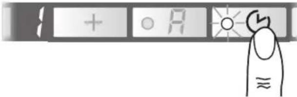
Switching off
With fan run-on started from manual mode:
Press the ○ 🎨 button.
text_image
A + O A ≈☐ The fan runs at the setting last selected.
☐ The dot on the display flashes.
□ After 10 minutes the fan switches off and the displays go out.
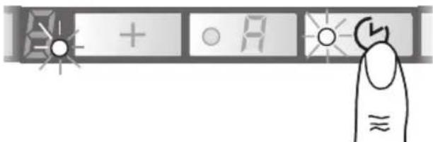
With fan run-on started from automatic mode:
Press the ○ 🎨 button.
☐ Fan run-on does not start until the automatic function has switched the fan back to Setting ^1 .
☐ The dot on the display flashes.
☐ After 10 minutes the fan switches off and the displays go out.
Without fan run-on:
Press the Ⓐ button.
text_image
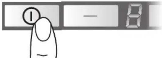
I — 8Light
☐ The light can be used at any time, even when the appliance has been switched off.
Switching on/off:
Press the 🔊 button.
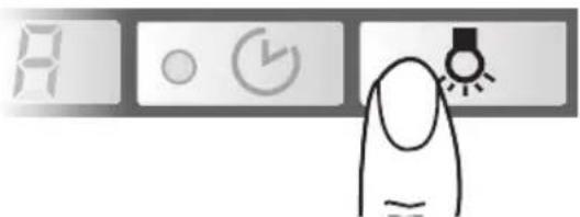
text_image
A ○ ← →Special functions
Adjusting the sensitivity of the sensor control:
- Press and hold down the automatic button.
- To display the current sensitivity, press the + or - button.
- You can now change the sensitivity of the sensor control by pressing the + or - button.
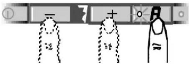
text_image
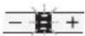
Diagram showing three labeled objects with symbols and dashed lines, possibly illustrating a physical or educational concept.□ Factory setting: 7.
☐ Lowest setting: ☐.
☐ Highest setting: 9.
Switching on the light automatically, e.g. via a timer:
☐ Fan and light must be switched off.
Switching on:
Simultaneously press the 🔒 and① buttons.
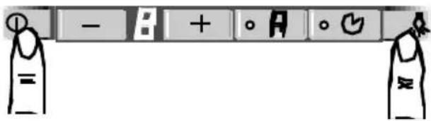
text_image
- B + o A o G =☐ After approx. 3 seconds the light switches on to acknowledge the setting.
Switching off:
Repeat the process with the light switched on.
☐ After approx. 3 seconds the light switches off to acknowledge the setting.
Filters and maintenance
Grease filters:
Metal filters are used to trap the greasy element of the vapours that develop during cooking.
The filter mats are made from non-combustible metal.
Caution:
As the filter becomes more and more saturated with grease, not only does the risk of it catching fire increase but the efficiency of the extractor hood can also be adversely affected.
Important:
By cleaning the metal grease filters at appropriate intervals, the possibility of them catching fire as a result of a build-up of heat such as occurs when deep-fat frying or roasting is taking place, is reduced.
Saturation indicator:
When the grease filters reach saturation point, an acoustic signal is sounded for 10 seconds after the fan has switched off, and an = appears in the display. The grease filters should be cleaned straight away.
Cleaning the metal grease filters:
☐ The filters can be cleaned in a dishwasher. It is however possible that they will become slightly discoloured.
Important:
Metal filters that are saturated with grease should not be washed together with other dishes etc.
☐ When cleaning the filters by hand, soak them in hot soapy water first of all. Then brush the filters clean, rinse them thoroughly and leave the water to drain off.
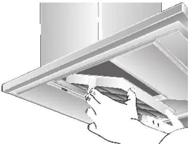
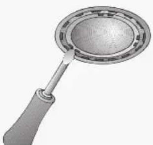
Removing and inserting the metal grease filters:
Warning: The halogen bulbs must be switched off and cool.
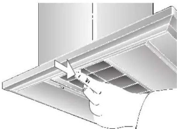
- Press the catch on the grease filters inwards and fold the filters down.
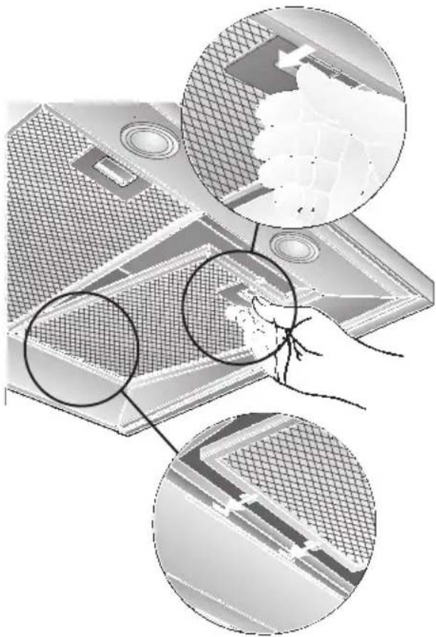
natural_image
Diagram showing three views of a device with mesh patterns and a magnified inset of its top surface (no text or symbols present)- Clean the filters.
- Insert the clean filters back into the hood.
- Cancel the = in the display.
☐ Press the Ⓐ button for at least 3 seconds.
The = is cancelled.
Filters and maintenance
Activated carbon filter:
For neutralizing odours in recirculating mode.
Inserting the filter:
Warning: The halogen bulbs must be switched off and cool.
-
Remove the metal filters (see "Removing and inserting the metal grease filters").
-
Insert the activated carbon filter.
natural_image
Illustration of a hand opening a ceiling-mounted shelf with shelves (no text or symbols visible)-
Engage the catches at both sides.
-
Insert the metal grease filters (see "Removing and inserting the metal grease filters").
-
Cancel the in the display.
☐ Press the Ⓑ button for at least 3 seconds. The ☐ is cancelled.
Saturation indicator:
When the activated carbon filter reaches saturation point, an acoustic signal is sounded for 10 seconds after the fan has switched off, and a appears in the display. The activated carbon filter should be replaced straight away.
Removing the filter:
Warning: The halogen bulbs must be switched off and cool.
- Remove the metal filters.
- Press the catches at both sides of the filter inwards and lift the carbon filter down and out.
natural_image
Illustration of a hand using a tool to lift or adjust a metal bracket (no text or symbols visible)- Insert the metal grease filters.
Replacing the activated carbon filter:
☐ A replacement filter can be obtained from any authorized dealer (see optional accessories). ☐ Use original filters only. By doing so you will obtain maximum performance from your extractor hood.
Disposing of the old activated carbon filter:
☐ There are no pollutants in the activated carbon filters. They can therefore be disposed of as part of your normal domestic refuse.
Cleaning and care
Disconnect the extractor hood from the electricity supply by pulling out the mains plug or switching it off at the fuse box.
☐ At the same time as you clean the grease filters, clean off any grease from all accessible parts of the housing. This significantly reduces the fire hazard and ensures that the extractor hood performs as effectively as possible.
☐ Use a hot detergent solution or a mild window cleaner to clean the canopy of the extractor hood.
☐ Do not scrape off any dirt that has dried on but loosen it up with a damp cloth.
☐ Do not use abrasive cleaning agents or sponges that could cause scratches.
☐ Note: Do not use alcohol (spirit) on plastic parts, otherwise the surface may become matt in appearance.
Caution: Ensure that the kitchen is adequately ventilated. Avoid naked flames!
⚠ Clean the operating buttons with a mild soapy solution and a soft, damp cloth only. Do not use stainless-steel cleaner to clean the operating buttons.
Stainless steel surfaces:
□ Use a mild non-abrasive stainless steel cleaner.
□ Clean the surface in the same direction as it has been ground and polished.
Do not use any of the following to clean stainless steel surfaces: abrasive sponges, cleaning agents containing sand, soda, acid or chloride!
Aluminium and plastic surfaces:
☐ Use a soft, non-linting window cloth or micro-fibre cloth.
☐ Do not use dry cloths.
☐ Use a mild window cleaning agent.
☐ Do not use aggressive, acidic or caustic cleaners.
☐ Do not use abrasive agents.
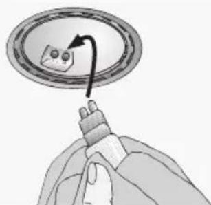
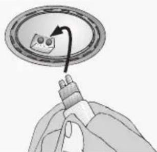
Replacing the light bulbs
- Switch off the extractor hood and pull out the mains plug or switch off the electricity supply at the fuse box.
When switched on, the halogen bulbs become very hot. Even for some time after the bulbs have been switched off there is still a risk of burns. - Remove the bulb ring with a screwdriver or similar tool.
natural_image
Illustration of a magnifying glass with a handle and circular lens (no text or symbols)- Replace the halogen light bulb (conventional halogen bulb, 12 Volt, max. 20 Watt, G4 cap). Caution: Refer for plug-in lampholder. Take hold of the bulb with a clean cloth.
natural_image
Illustration of a hand holding a device with a curved arrow pointing to a circular component (no text or symbols)- Re-insert the bulb ring.
- Plug the appliance into the mains or switch it on at the fuse box.
Note: If the light does not function, check that the bulbs have been inserted correctly.
Setting the saturation indicator
If it becomes necessary to change the operating mode (exhaust-air/recirculating mode), the saturation indicator for the filters must also be altered (see Installation Instructions).
If you encounter a problem
If an or appears in the display:
☐ See "Filters and maintenance" Section.
If is not possible to operate the extractor hood:
☐ Disconnect the extractor hood from the mains electricity supply by pulling out the plug or switching it off at the main fuse box.
Wait for approx. 1 minute and then switch it on again.
If you have any questions or if a fault occurs, please call Customer Service.
(See list of Customer Service representatives).
When you call, please quote the following:
E-Nr.
FD
Enter the relevant numbers into the box above. The E-Nr. (product no.) and FD (production date) are shown on the nameplate which can be seen inside the extractor hood after the filter frame has been detached.
Important information
⚠️ Old appliances are not worthless rubbish. If they are disposed of in an environment-friendly manner, valuable raw materials can be recovered for use again. Before you dispose of an old appliance, make sure that it has been rendered inoperative.
⚠️ Your new appliance was protected on its way to you by the packaging. None of the materials cause pollution to the environment and all can be recycled for use again. Please help to protect the environment and dispose of the packaging in an environment-friendly manner.
You can obtain information about the best method disposing of old appliances and packaging from your dealer or local municipal council.
⚠ The extractor hood can be used in either exhaust-air or recirculating mode.
⚠️ Always mount the extractor hood over the centre of the hob.
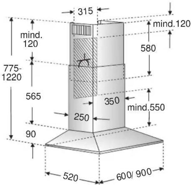
⚠️ Minimum distance between electric hob and bottom edge of extractor hood: 550 mm, Fig. 1.
Additional notes concerning gas cookers:
When installing gas hotplates, comply with the relevant national statutory regulations (e.g. in Germany: Technische Regeln Gasinstallation TRGI).
⚠ The relevant regulations and installation notes provided by the manufacturer of the gas cooker must be observed in all cases.
⚠ The extractor hood may be installed next to only one full-height cupboard or high wall. Gap to be at least 50 mm.
⚠ The installation of the extractor hood above gas cooking devices, at a minimum height of 650 mm – Fig. 1 – is permitted provided that the following nominal heat loads (Hs) are not exceeded:
Gas cookers
Load of one hotplate max. 3.0 kW Load of all hotplates max. 8.3 kW Load of the oven max. 3.9 kW
Gas hobs
Load of one hotplate max. 3.9 kW Load of all hotplates max. 11.3 kW
☐ Gas glass-ceramic hotplate
The data on nominal heat loads do not apply to gas glass-ceramic hotplates. Be sure to observe the instructions provided by the manufacturer of the hotplate.
Solid-fuel cookers
The maximum nominal heat loads and the minimum distance are the same as for gas cookers.
⚠️ Installation of the extractor hood over a solid-fuel burner which could constitute a potential fire hazard (e.g. due to flying sparks) is only permitted if the burner is equipped with an enclosed, non-removable cover and all country-specific regulations are observed. This restriction does not apply to gas cookers and gas hobs.
⚠ The smaller the gap between extractor hood and hob, the greater the likelihood that rising steam will cause condensation to form on the hood.
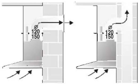
Prior to installation
Exhaust-air mode
text_image
120 150 120 150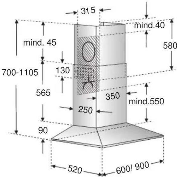
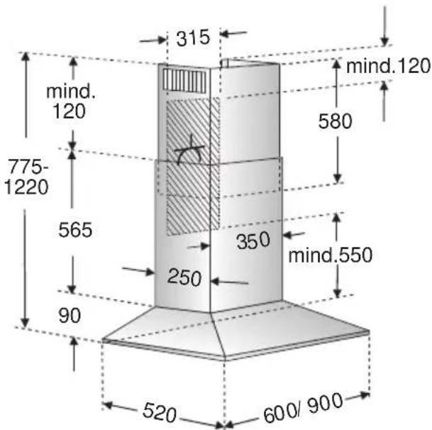
text_image
315 mind.40 mind. 45 700-1105 130 565 350 mind.550 250 90 520 600/ 900The exhaust air is discharged upwards through a ventilation shaft or directly through the outside wall into the open.
Exhaust air should neither be directed into a smoke or exhaust flue that is currently used for other purposes, nor into a shaft that is used for ventilating rooms in which stoves or fireplaces are also located.
Exhaust air may be discharged in accordance with official and statutory regulations only (e.g. national building regulations).
Local authority regulations must be observed when discharging air into smoke or exhaust flues that are not otherwise in use.
When the extractor hood is operated in exhaust-air mode simultaneously with a different burner which also makes use of the same chimney (such as gas, oil or coal-fired heaters, continuous-flow heaters, hot-water boilers) care must be taken to ensure that there is an adequate supply of fresh air which will be needed by the burner for combustion.
Safe operation is possible provided that the underpressure in the room where the burner is installed does not exceed 4 Pa (0.04 mbar).
This can be achieved if combustion air can flow through non-lockable openings, e.g. in doors, windows and via the air-intake/exhaust-air wall box or by other technical measures, such as reciprocal interlocking, etc.
If the air intake is inadequate, there is a risk of poisoning from combustion gases which are drawn back into the room.
An air-intake/exhaust-air wall box by itself is no guarantee that the limiting value will not be exceeded.
Note: When assessing the overall requirement, the combined ventilation system for the entire household must be taken into consideration. This rule does not apply to the use of cooking appliances, such as hobs and ovens.
Unrestricted operation is possible if the extractor hood is used in recirculating mode – with activated carbon filter.
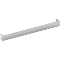
If the exhaust air is going to be discharged into the open, a telescopic wall box should be fitted into the outside wall.
Prior to installation
For optimum extractor hood efficiency:
☐ Short, smooth air exhaust pipe.
☐ As few bends in the pipe as possible.
☐ Diameter of pipe to be as large as possible and no tight bends in pipe.
If long, rough exhaust-air pipes, many pipe bends or smaller pipe diameters are used, the air extraction rate will no longer be at an optimum level and there will be an increase in noise.
Round pipes:
We recommend Internal diameter: 150 mm (at least 120 mm).
☐ Flat ducts must have an internal cross-section that equates to that of round pipes.
There should be no sharp bends.
∅ 120 mm approx. 113 cm
∅ 150 mm approx. 177 cm
☐ If pipes have different diameters: Insert sealing strip.
☐ For exhaust-air mode, ensure that there is an adequate supply of fresh air.
Circulating-air mode
☐ With activated carbon filter if exhaust-air mode is not possible.
⚠ The complete installation set can be obtained from specialist outlets. The corresponding accessory numbers can be found at the end of these operating instructions.
natural_image
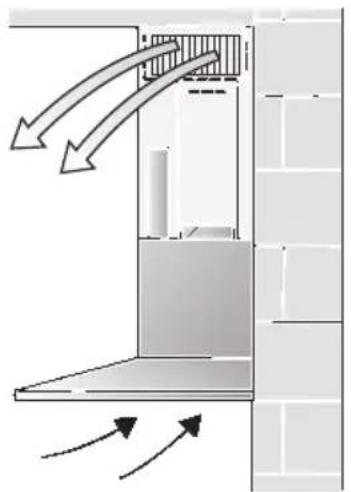
Diagram of airflow or heat transfer between a building interior and wall, showing directional arrows (no text or symbols)Connecting a 150 mm exhaust-air pipe:
☐ Mount the pipe directly onto the air outlet on the hood.
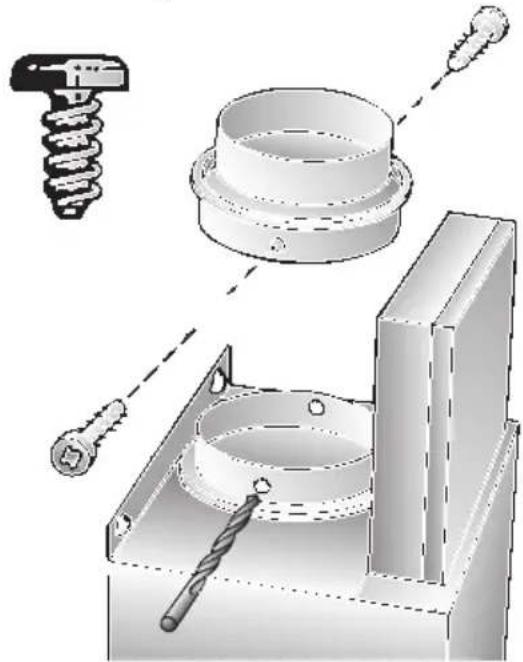
Connecting a 120 mm exhaust-air pipe:
☐ Insert the reducing connector into the air connector, drill 2x ∅ 3 mm holes and screw together.
natural_image
Technical illustration of a mechanical assembly with tool, screw, and housing components (no text or symbols)☐ Attach the exhaust-air pipe to the reducing connector.
text_image
315 mind. 120 775- 1220 565 90 250 350 mind.550 580 mind.120 520 600/900Electrical connectionPrior to installation
Preparing the wall
☐ The wall must be flat and perpendicular.
☐ Ensure that the wall is capable of providing a firm hold for mounting screws and plugs.
□ Appliances with a rear light:
A recess panel or tiles fitted to the wall directly under the extractor hood must not project by more than 15 mm, otherwise the light cover may be damaged.
Weight in kg:
| Exhaust air | Recirculating air | |
| 20,260 cm | 22,4 | |
| 23,2 25,490 cm | ||
We reserve the right to construction changes within the context of technical development.
Changing over from exhaust-air to recirculating mode
Changing the electronic control system to recirculating mode:
☐ The standard factory setting is for operation in exhaust-air mode.
☐ To change the mode, the extractor hood must have been connected up and should be switched off.

- Press and hold down the Ⓐ button.
- Press the ○ 🎨 button for approx. 3 seconds.
□ A ⊥ is displayed.
- Release the buttons.
☐ The display goes out shortly afterwards.
Resetting to exhaust-air mode:
- Repeat the procedure.
□ A ≡ is displayed. - Release the buttons.
☐ The display goes out shortly afterwards.
WARNING: THIS APPLIANCE MUST BE EARTHED
IMPORTANT: Fitting a Different Plug:
The wires in the mains lead are coloured in accordance with the following code:
Green and Yellow – Earth
Blue - Neutral
Brown – Live
If you fit your own plug, the colours of these wires may not correspond with the identifying marks on the plug terminals.
This is what you have to do:
- Connect the green and yellow (Earth) wire to the terminal in the plug marked 'E' or with the symbol (≡), or coloured green or green and yellow.
- Connect the blue (Neutral) wire to the terminal in the plug marked 'N' or coloured black.
- Connect the brown (Live) wire to the terminal marked 'L', or coloured red.
The extractor hood should only be connected to an earthed socket that has been installed according to relevant regulations.
If possible, site the earthed socket directly behind the chimney panelling.
Electrical data:
Are to be found on the name plate inside the appliance after removal of the filter frame.
⚠️ Before undertaking any repairs, always disconnect the extractor hood from the electricity supply.
Length of the connecting cable: 1.30 m.
If it is necessary to wire the extractor hood directly into the mains:
The extractor hood should only be connected to the electricity supply by a properly qualified electrician.
A separator must be installed in the household circuit. A suitable separator is a switch that has a contact gap of more than 3 mm and interrupts all poles. Such devices include circuit breakers and contactors.
This extractor hood corresponds to EC regulations concerning RF interference suppression.
Installation
This extractor hood is intended to be mounted onto the kitchen wall.
- Remove the grease filter (refer to Operating Instructions).
- Draw a line on the wall from the ceiling to the lower edge of the hood at the centre of the location where the hood is going to be mounted.
- Using the template, mark positions on the wall for the screws.
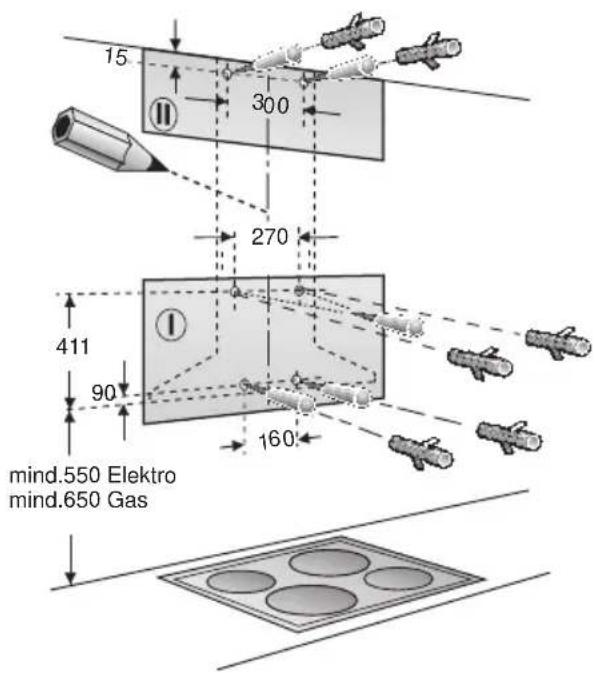
⚠ Ensure that the minimum distance between the hob and the extractor hood is maintained – 550 mm for an electric hob and 650 mm for a gas hob. The bottom edge of the template equates to the lower edge of the extractor hood.
- Drill 4 x ∅ 8 mm holes for the extractor hood and 2 x ∅ 8 mm holes for the chimney panelling. Insert plugs into the holes so that they are flush with the wall.
text_image
15 300 270 411 90 160 mind.550 Elektro mind.650 GasNote: Take into account any special accessories that are going to be fitted.
- Attach the fixing bracket for the chimney panelling using two hexagon head cap screws.
- Screw in the two upper hexagon head cap screws leaving them extended by approx. 5 mm.
- Attach the extractor hood to the screws.
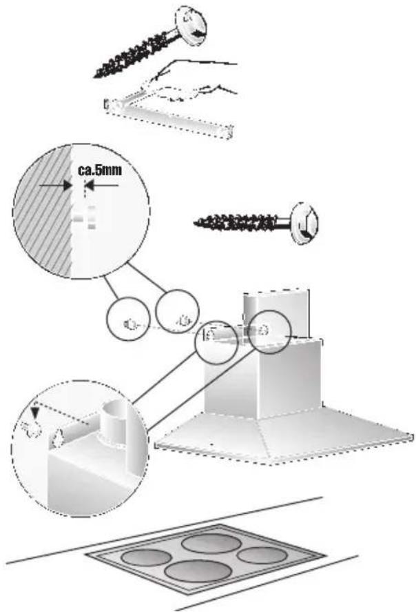
text_image
ca.5mm 15° 3Installation
- Screw in the two lower hexagon head cap screws.
⚠️ Before the 4 screws are tightened down, align the extractor hood properly.
9. Stick protective film over the holes of the 2 lower mounting bolts in the protective grid.
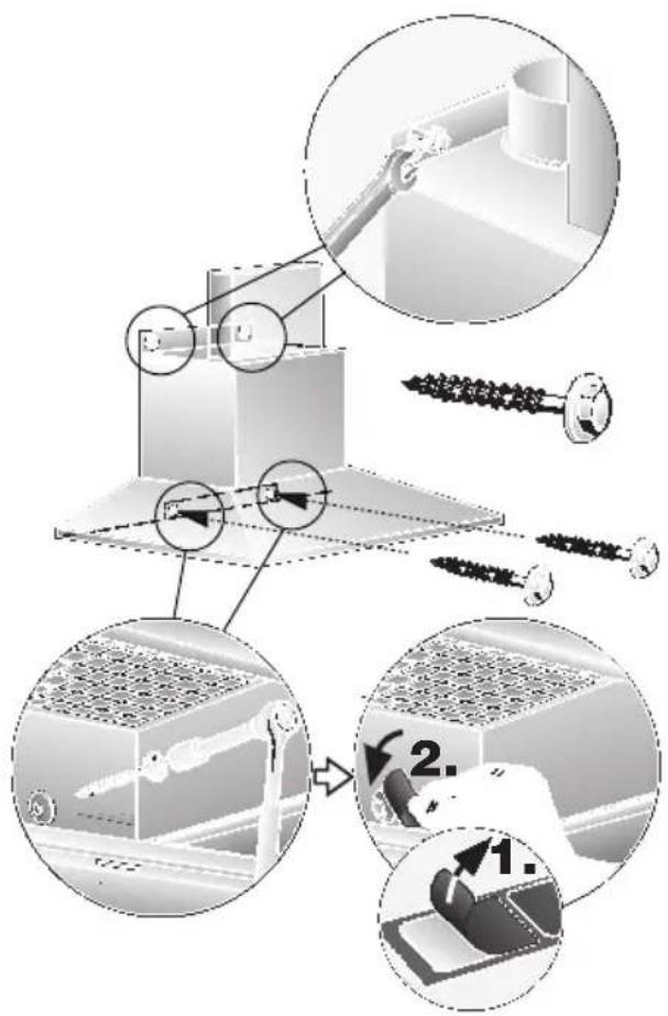
text_image
Technical diagram illustrating assembly steps of a mechanical assembly with labeled components and process flow arrows.- Connect up the air outlet pipe.
- Connect the hood to the electricity supply.
- Remove the protective film from the two flue ducts.
⚠️ Take care not to damage the stainless steel surfaces which are susceptible to scratches etc.
- Push both sections of the flue panelling together (slots in the upper section must be pointing downwards) and insert into the opening in the extractor hood.
⚠️ Protect the cover panels from scratches, for example by laying the template used for marking the wall over the top edge of the lower section.
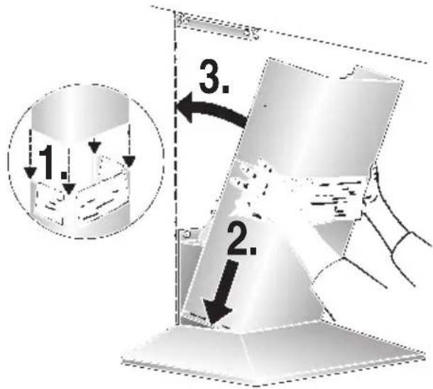
text_image
1. 2. 3.- Slide out the upper section and attach it to the mounting brackets at the sides with two screws.
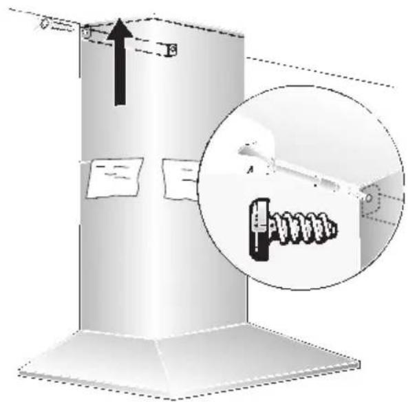
text_image
Diagram illustrating a mechanical or electrical component with labeled parts and an inset magnified view showing a device with a spring-like component.- Insert the grease filter (refer to Operating Instructions).
text_image
Hand-drawn interface with icons for addition, summing, rotation, and timer, plus a finger pointing to the digit 'F' on a finger.Aspiration intensive:
text_image
Diagram showing three labeled objects with symbols and dashed lines, possibly illustrating a physical or engineering concept.text_image
- B + o A o G =natural_image
Diagram showing three views of a solar panel with magnified insets highlighting internal structure (no text or symbols)natural_image
Illustration of a hand opening a ceiling-mounted shelf with shelves (no text or symbols visible)natural_image
Illustration of a hand inserting a Y-shaped arrow into a metal panel (no text or symbols)natural_image
Illustration of a circular object with a handle and textured surface, resembling a stylus or magnifying glass (no text or symbols)natural_image
Illustration of a hand holding a device with a circular component and an arrow indicating rotation (no text or symbols)natural_image
Diagram showing airflow or heat transfer between a building structure with arrows indicating direction (no text or symbols)text_image
manchons.text_image
Technical diagram illustrating assembly steps of a mechanical component with labeled parts and numbered instructions.text_image
Diagram illustrating a mechanical assembly or installation process with labeled components and directional arrows, including a magnified inset showing internal components.text_image
Hand-drawn icon showing a finger pointing to a timer or function button with plus, sine, and clock symbolsVentilatorstanden:
text_image
Diagram showing three labeled components with symbols and dashed lines, possibly illustrating a schematic or schematic.□ Fabrieksinstelling: 7.
□ Laagste instelling: □.
☐ Hoogste instelling: 9.
text_image
- B + o A o G =natural_image
Diagram showing three views of a solar panel installation with magnified insets (no text or symbols)natural_image
Illustration of a hand opening a ceiling-mounted shelf with shelves (no text or symbols visible)natural_image
Illustration of a hand using a tool to lift or adjust a metal bracket (no text or symbols visible)natural_image
Illustration of a magnifying glass with a handle and circular lens (no text or symbols)Let op: plugfitting.
natural_image
Illustration of a hand holding a circular object with an arrow pointing to it, no text or symbols present.natural_image
Diagram showing airflow or heat transfer between a wall-mounted structure and a brick wall (no text or symbols)natural_image
Technical illustration of a mechanical assembly with labeled components (no text or symbols present)text_image
ca.5mm 15° 3Inbouwen
text_image
Technical diagram illustrating assembly steps of a mechanical component with labeled parts and numbered instructions.text_image
Technical diagram showing a mechanical assembly with labeled components and an inset magnified view of a spring mechanism.text_image
A + O F ≈text_image
A O C Light BulbFunzioni speciali
text_image
Diagram showing three labeled objects with symbols and dashed lines, possibly illustrating a physical or educational concept.text_image
- B + o A o G =natural_image
Diagram showing a hand cleaning a solar panel with magnified views of internal components (no text or symbols)natural_image
Illustration of hands installing or adjusting a ceiling panel (no text or symbols visible)natural_image
Illustration of a hand using a tool to lift or adjust a metal panel (no text or symbols visible)natural_image
Illustration of a magnifying glass with a handle and circular lens (no text or symbols)- Sostituire la lampadina alogena (lampadina alogena commerciale, 12 Volt, max. 20 Watt, attacco G4).
natural_image
Illustration of a hand holding a device with a circular component and an arrow indicating rotation (no text or symbols)natural_image
Diagram of airflow or heat transfer between a building interior with directional arrows indicating flow direction (no text or symbols)natural_image
Technical illustration of a mechanical assembly with tool, gear, and component (no text or symbols)text_image
Technical diagram illustrating assembly steps of a mechanical component with labeled parts and process flow arrowstext_image
Diagram illustrating a mechanical or electrical component with directional arrows and a magnified inset showing internal components.text_image
Hand-drawn interface with icons for addition, summing, rotation, and navigation controlstext_image
Hand-drawn interface toolbar with plus, circle, and sun icons, next to a finger pointing to the right button.text_image
Diagram showing three labeled figures with symbols and dashed lines, possibly illustrating a process or concept.text_image
- B + o A o G =natural_image
Diagram showing three views of a solar panel installation with magnified insets highlighting structural details (no text or symbols present)natural_image
Illustration of a hand installing or adjusting a ceiling panel (no text or symbols visible)natural_image
3D illustration of a hand pressing down on a metal bracket with a tool, no text or symbols presentnatural_image
Illustration of a circular object with a handle and textured surface, resembling a magnifying glass or tool (no text or symbols visible)natural_image
Illustration of a hand holding a cable with a circular component above, showing a curved arrow indicating rotation (no text or symbols)natural_image
Diagram of airflow or heat transfer between a building structure with arrows indicating direction (no text or symbols)text_image
ca.5mm 16° 3Montaje
text_image
Technical diagram illustrating assembly steps of a mechanical component with labeled parts and numbered instructions.text_image
Diagram illustrating a mechanical assembly or mounting process with an inset magnified view showing a tool interacting with a component.text_image
A ○ ← ● 灯Funções especiais
text_image
Diagram showing three labeled figures with symbols and arrows, possibly illustrating a concept or concept in physics.text_image
- B + o A o G =natural_image
Illustration of a device with three circular insets showing close-ups of internal components (no text or symbols)natural_image
Illustration of a hand opening a ceiling-mounted shelf with shelves (no text or symbols visible)natural_image
Illustration of a hand inserting a triangular component into a metal panel (no text or symbols)- Recolocar o filtro de gordura.
natural_image
Illustration of a magnifying glass with a handle and circular lens (no text or symbols)- Substituir a lâmpada de halogéneo (lâmpada de halogéneo corrente no mercado, 12 Volt, máx. 20 Watt, casquilho G4).
natural_image
Illustration of a hand holding a small object with a curved arrow pointing to a circular component (no text or symbols)natural_image
Diagram showing airflow or heat transfer between a building facade and wall, with arrows indicating direction (no text or symbols)natural_image
Technical illustration of a mechanical assembly with labeled components (no text or symbols present)text_image
Technical diagram illustrating assembly steps of a mechanical assembly with labeled components and process flow arrows.text_image
Diagram illustrating a mechanical or electrical device with labeled components and directional arrows, including a magnified inset showing internal components.text_image
Hand-drawn interface with icons for addition, summing, rotation, and navigation controlstext_image
Diagram showing three labeled objects with symbols and dashed lines, possibly illustrating a physical or engineering concept.text_image
- B + o A o G =natural_image
Diagram showing three views of a device with mesh patterns and a magnified inset highlighting a grid interface (no text or symbols present)natural_image
Illustration of a hand installing or adjusting a ceiling panel (no text or symbols visible)natural_image
3D illustration of a hand inserting a triangular component into a metal panel (no text or symbols)natural_image
Illustration of a magnifying glass with a handle and circular lens (no text or symbols)natural_image
Illustration of a hand holding a device with a curved arrow pointing to a circular component (no text or symbols)natural_image
Diagram showing airflow or heat transfer between a wall-mounted structure with arrows indicating direction (no text or symbols)natural_image
Technical illustration of a mechanical assembly with tool, spring, and base components (no text or symbols)text_image
ca.5mm R1Montering
text_image
Technical diagram illustrating assembly steps of a mechanical component with labeled parts and numbered instructions.text_image
Diagram illustrating a mechanical or electrical setup with labeled components and directional arrows, including a magnified inset showing a device labeled 'A'.text_image
Diagram showing three labeled objects with symbols and dashed lines, possibly indicating positions or states in a technical or scientific context.text_image
- B + o A o G =natural_image
Diagram showing three views of a microenclosed panel with mesh patterns, highlighting a specific component (no text or symbols present)natural_image
Illustration of a hand opening a ceiling-mounted shelf with a tray (no text or symbols visible)natural_image
Illustration of a hand using a tool to lift or adjust a metal bracket (no text or symbols visible)natural_image
Illustration of a magnifying glass with a handle and circular lens (no text or symbols)- Skift ut halogenpæren (vanlig halogenpære som finnes i handelen, 12 volt, max. 20 watt, sokkel G4).
Pass på: Stikkontaktholder. Bruk en ren klut når du tar på lyspæren.
natural_image
Illustration of a hand holding a device with a circular component and an arrow indicating rotation (no text or symbols)natural_image
Diagram showing airflow or heat transfer between a building structure with arrows indicating direction (no text or symbols)natural_image
Technical illustration of a mechanical assembly with tool, spring, and drill bit (no text or symbols)text_image
Technical diagram illustrating assembly steps of a mechanical assembly with labeled components and process flow arrows.-
Legg opp rørforbindelsen.
-
Foreta den elektriske tilkoplingen.
-
Trekk av beskyttelsesfolien på begge sider av pipeblenden.
text_image
Diagram illustrating a mechanical or electrical device with labeled components and directional arrows, including a magnified inset showing internal components.text_image
Diagram showing a hand pointing to a toolbar with icons for addition, subtraction, and rotation.text_image
Diagram showing three labeled objects with symbols and dashed lines, possibly illustrating a conceptual or experimental setup.text_image
- B + o A o G =natural_image
Diagram showing three views of a device with mesh patterns and a magnified inset highlighting a grid structure (no text or symbols present)natural_image
Illustration of a hand opening a window frame (no text or symbols visible)natural_image
Illustration of a hand inserting a triangular component into a metal panel (no text or symbols)natural_image
Illustration of a magnifying glass with handle and circular lens (no text or symbols)natural_image
Illustration of a hand holding a small object with a curved arrow pointing to a circular component (no text or symbols)natural_image
Diagram showing airflow or heat transfer between a building facade and wall, with arrows indicating direction (no text or symbols)natural_image
Technical illustration of a mechanical assembly with tool, spring, and drill bit (no text or symbols)text_image
Technical diagram illustrating assembly steps of a mechanical component with labeled parts and numbered instructions.text_image
Diagram illustrating a mechanical or electrical component with an inset close-up showing a tool interacting with a spring-like device.text_image
Hand-drawn interface with icons for addition, summing, rotation, and navigation controlsVentilatortrin:
text_image
Hand-drawn interface toolbar with icons for addition, rotation, and navigation buttonstext_image
Diagram showing three labeled components with symbols and dashed lines, possibly illustrating a schematic or schematic.text_image
- B + o A o G =natural_image
Diagram showing three views of a microchip with mesh patterns and a magnified inset highlighting a specific component (no text or symbols present)natural_image
Illustration of a hand holding a shelf with a tray, no text or symbols visiblenatural_image
Illustration of a hand inserting a triangular tool into a metal frame (no text or symbols)- Sæt fedtfiltrene ind.
natural_image
Illustration of a magnifying glass with a handle and circular lens (no text or symbols)- Udskift halogenlampen (almindelig halogenlampe, 12 V, max. 12 W, sokkel G4).
natural_image
Illustration of a hand holding a device with a curved arrow pointing to a circular component (no text or symbols)natural_image
Technical illustration of a mechanical assembly with tool, spring, and base components (no text or symbols)natural_image
Diagram of airflow or heat transfer between a building facade and wall, showing curved arrows indicating direction (no text or symbols)