USER MANUAL MasterFlush MF 7120 DOMETIC
Mounting instructions. 93
NO
Macerator toilet
Mounting instructions 103
F1
Electrical connection
Installation instructions 113
PL
Cancer and Reproductive Harm
www.P65Warnings.ca.gov
Copyright
© 2024 Dometic Group. The visual appearance of the contents of this manual is protected by copyright and design law. The underlying technical design and the products contained herein may be protected by design, patent or be patent pending. The trademarks mentioned in this manual belong to Dometic Sweden AB. All rights are reserved.
Service center and dealer locations Visit: www.dometic.com
Please read these instructions carefully and follow all instructions, guidelines, and warnings included in this product manual in order to ensure that you install, use, and maintain the product properly at all times. These instructions MUST stay with this product.
By using the product, you hereby confirm that you have read all instructions, guidelines, and warnings carefully and that you understand and agree to abide by the terms and conditions as set forth herein. You agree to use this product only for the intended purpose and application and in accordance with the instructions, guidelines, and warnings as set forth in this product manual as well as in accordance with all applicable laws and regulations. A failure to read and follow the instructions and warnings set forth herein may result in an injury to yourself and others, damage to your product, or damage to other property in the vicinity. This product manual, including the instructions, guidelines, and warnings, and related documentation, may be subject to changes and updates. For up-to-date product information, please visit www.dometic.com.
Contents
1 Related documents 5 2 Explanation of symbols and safety instructions 5 3 Intended use 6 4 General information 7 5 Specifications 8 6 Installation 9 7 Disposal 13 8 Warranty information 13

Find the quick start guide online at http://qr.dometic.com/bejZbz

Find the operating manual online at http://qr.dometic.com/beetav
2 Explanation of symbols and safety instructions
This manual has safety information and instructions to help you eliminate or reduce the risk of accidents and injuries.

This is the safety alert symbol. It is used to alert you to potential physical injury hazards. Obey all safety messages that follow this symbol to avoid possible injury or death.
2.2 Understand signal words
A signal word will identify safety messages and property damage messages, and also will indicate the degree or level of hazard seriousness.

WARNING
Indicates a hazardous situation that, if not avoided, could result in death or serious injury.
NOTICE: Used to address practices not related to physical injury.

Indicates additional information that is not related to physical injury.
2.3 Supplemental Directives
To reduce the risk of accidents and injuries, please observe the following directives before proceeding to install or service this appliance:
Read and follow all safety information and instructions.
- Read and understand these instructions before operating or servicing this product.
- Dometic recommends that a qualified marine technician or electrician install or service this product. Equipment damage, injury to personnel or death could result from improper installation. The installation must comply with all applicable local or national codes.
2.4 General safety messages

WARNING: Flooding hazard. Failure to obey the following warnings could result in death or serious injury.
- If the toilet is connected to any through-the-hull fittings, properly installed seacocks must be installed in all piping connected to through-the-hull fittings. Seacocks must be easily accessible to all users of the toilet or secondary valves fitted in hoses where they are easily accessible. All valves must be full bore valves and of marine quality. Screw-to-close gate valves are not recommended.
- If the toilet is connected to any through-the-hull fittings, all flexible hoses must be of marine sanitation quality and must be secured to any fittings (such as those at seacock, vented loop or toilet) with two stainless steel, worm-drive hose band clamps at each connection. Connections must be checked frequently for integrity.
- If the toilet rim is ever less than 8 in. (20 cm) above the highest possible waterline at any time (during any conditions of heel, load, or trim) and is connected to any through-the-hull fittings, properly positioned ventilated (vented) loops must be installed in intake (if connected to raw water) or discharge piping to prevent potential back siphonage of seawater into the boat. Vented loops must be equipped with integral check valve that permits air into line to prevent siphoning.
- If toilet uses raw water for flushing at any time, a raw water pump controlled by an automatically operating demand switch must not be installed. If the onboard water valve or any plumbing connections were to leak, the automatically operated pump would start and could flood the boat.
- Do not connect raw water flush toilet (models 7160, 7260) to an onboard pressurized water system.
- Before beginning any work on this product, be sure that all electrical power to the unit has been turned off and that the seacocks are in the closed or off position.

WARNING: Electrical shock and/or fire hazard.
Follow all local regulations for electrical installations.
NOTICE: Overfilling the holding tank can cause serious damage to the sanitation system, such as rupturing the holding tank and releasing tank contents into the bilge. To prevent this possibility, Dometic recommends using a full tank shut-down relay. The full signal from the holding tank can be generated by an optional Dometic DTM01C tank monitor or DTM04 four-level tank monitor system.

Follow all local regulations for waste tank discharge.
3 Intended use
The Macerator toilet (hereinafter referred to as toilet or product) provides an electric-flush toilet that macerates waste and pumps it either to a holding tank or other effluent storage/disposal system, or overboard. Operated by a remote flush switch, the toilet allows the user to add water to the bowl (before or after flushing) and to flush the toilet by pushing a button. This toilet is designed for use in marine applications and is only suitable for the intended purpose and application in accordance with these instructions.
This manual provides information that is necessary for proper installation of the toilet. Poor installation and/or improper operating or maintenance will result in unsatisfactory performance and a possible failure. The manufacturer accepts no liability for any injury or damage to the product resulting from:
- Incorrect assembly or connection, including excess voltage
- Incorrect maintenance or use of spare parts other than original spare parts provided by the manufacturer
- Alterations to the product without express permission from the manufacturer
- Use for purposes other than those described in this manual
Dometic reserves the right to change product appearance and product specifications.
The images used in this document are for reference purposes only. Components and component locations may vary according to specific product models. Measurements may vary ±0.38 in. (10 mm).
4.1 Components
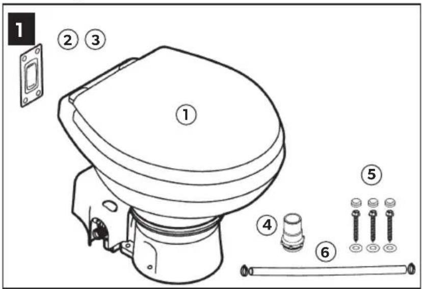
Packaging contents (Figure 1 on page 2)
| 1 Macerator toilet |
| 2 DFS-2F flush switch (standard - freshwater flush toilet) |
| 3 DFS-1F flush switch (standard - raw water flush toilet) |
| 4 1.5 in. (38 mm) discharge fitting |
| 5 Floor mounting hardware kit |
| 6 Water supply hose kit |
| Parts list1 |
| Quick start guide1 |
Not shown
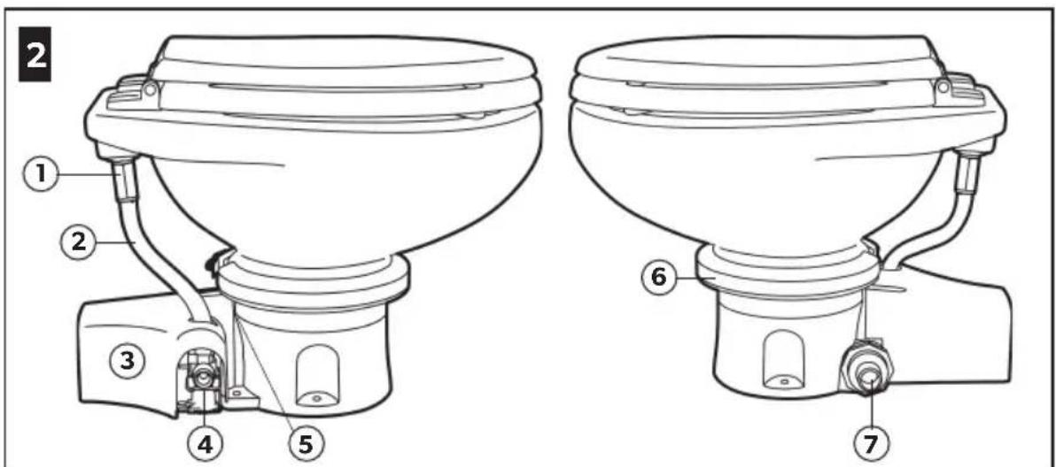
Toilet components (Figure 2 on page 2)
| 1 Rim flush check valve (freshwater toilet) or adapter (raw water model) |
| 2 Water supply hose |
| 3 Macerator pump (under plastic cover) |
| 4 Electric water valve (raw water model) |
| 5 Product ID label location |
| 6 Stainless steel compression band |
| 7 Discharge fitting |
4.2 Toilet system layouts
4.2.1 Above water line system
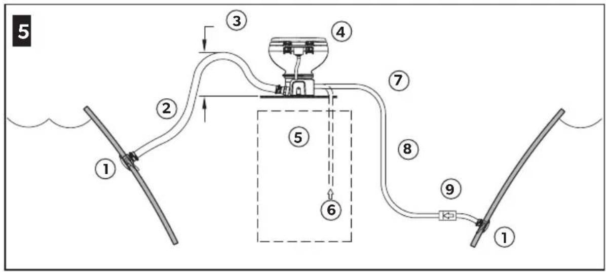
Toilet with direct overboard discharge
(Figure 5 on page 3)
| 1 Seacock |
| 2 1.0 in. (25 mm) or 1.5 in. (38 mm) ID hose |
| 3 Make loop 12.0 in. (305 mm) above the floor to retain water in the bowl |
| 4 Macerator toilet |
| 5 Freshwater supply
0.5 in. (13 mm) ID fresh water line |
| 6 From fresh water supply |
| 7 Seawater supply |
| 8 0.75 in. (19 mm) ID hose |
| 9 Check valve ensures that pump stays primed |
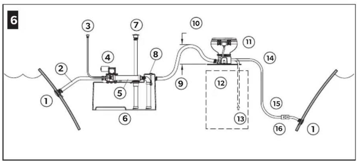
Toilet with holding tank discharge
| (Figure 6 on page 3) |
| 1 Seacock |
| 2 Add vented loop if holding tank is below the water line |
| 3 Vent fitting |
| 4 Discharge pump |
| 5 Vent filter |
| 6 Holding tank (cut-away view) |
| 7 Deck discharge |
| 8 Optional full tank level float |
| 9 1.0 in. (25 mm) or 1.5 in. (38 mm) ID hose |
| 10 Make loop 12.0 in. (305 mm) above the floor to retain water in the bowl |
| 11 Macerator toilet |
| 12 Freshwater supply
0.5 in. (13 mm) ID fresh water line |
| 13 From fresh water supply |
| 14 Seawater supply |
| 15 0.75 in. (19 mm) ID hose |
| 16 Check valve ensures that pump stays primed |
4.2.2 Below water line system
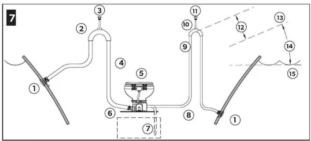
Toilet with direct overboard discharge
(Figure 7 on page 3)
1 Seacock 2 1.0 in. (25 mm) or 1.5 in. (38 mm) vented loop 3 Vent fitting 4 1.0 in. (25 mm) or 1.5 in. (38 mm) ID hose 5 Macerator toilet 6 Freshwater supply 7 0.5 in. (13 mm) ID fresh water line 8 Seawater supply 9 0.75 in. (19 mm) ID hose 10 0.75 in. (19 mm) vented loop with check valve 11 Vent fitting 12 8.0 in. (203 mm) minimum 13 Maximum heel 14 Waterline range 15 Static
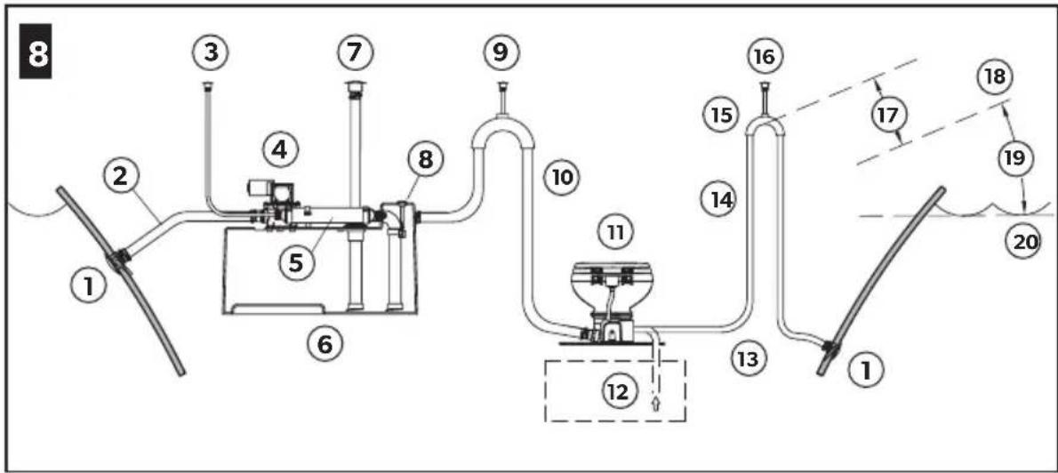
Toilet with holding tank discharge
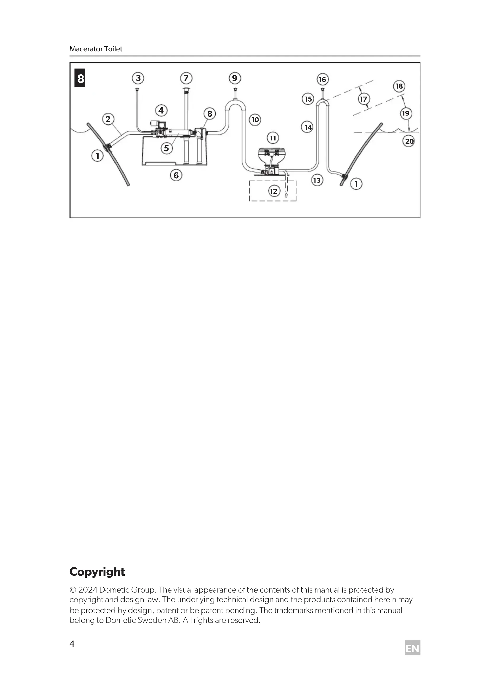
(Figure 8 on page 4)
1 Seacock 2 Add vented loop if the holding tank is below the waterline 3 Vent fitting 4 Discharge pump 5 Vent filter 6 Holding tank (cut-away view) 7 Deck discharge 8 Optional full tank level float 9 Vent fitting 10 1.0 in. (25 mm) or 1.5 in. (38 mm) ID hose 11 Macerator toilet 12 Freshwater supply 0.5 in. (13 mm) ID fresh water line
13 Seawater supply 14 0.75 in. (19 mm) ID hose 15 0.75 in. (19 mm) vented loop with check valve 16 Vent fitting 17 8.0 in. (203 mm) minimum 18 Maximum heel 19 Waterline range 20 Static
5 Specifications
5.1 Dimensions
7120, 7160 (standard bowl)
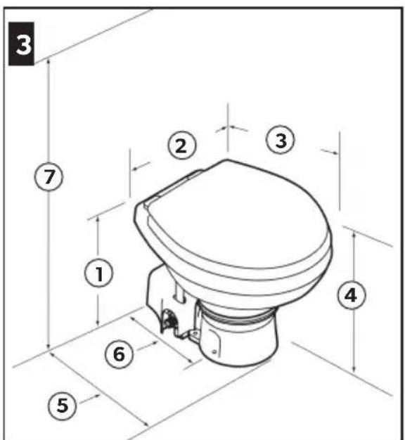
(Figure 3 on page 2)
1 14.8 in. (375 mm) 2 15.0 in. (381 mm) 3 19.0 in. (483 mm) 4 13.8 in. (349 mm) seat height 5 13.8 in. (349 mm) 6 10.0 in. (254 mm) 7 28.75 in. (730 mm) seat lid up
7220, 7260 (compact marine bowl)
(Figure 3 on page 2)
1 13.3 in. (337 mm) 2 14.5 in. (368 mm) 3 18.8 in. (476 mm) 4 12.3 in. (311 mm) seat height 5 13.8 in. (349 mm) 6 10.0 in. (254 mm) 7 26.3 in. (667 mm) seat lid up
Dometic flush switch panel
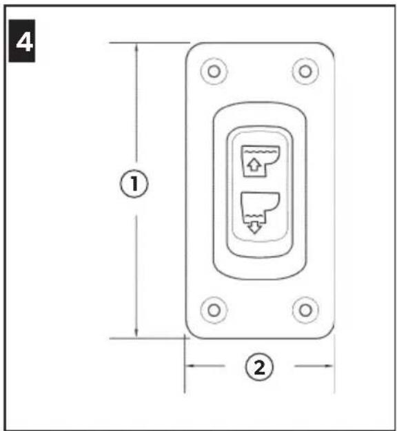
Figure 4 on page 2
1 3.25 in. (83 mm) 2 1.625 in. (41 mm)
5.2 Materials
| Toilet Vitreous ceramic |
| Toilet base Polypropylene |
| Domatic flush switch panel | Polystyrene (DFS-1F or DFS-2F); or powder-coated aluminum (DFST) |
5.3 Minimum System Requirements
| Electrical Power draw 20 amps
/12 VDC;
10 amps
/24 VDC | |
| Circuit breaker | 25 amps
/12 VDC;
15 amps
/24 VDC | |
| Wiring¹ | 12 gauge
Up to 25 ft
(7.6 m) total
circuit | |
| Water Supply | Fitting size
Supply hose
ID | 0.5 in. NPT -
fresh water flush
toilet |
| 0.75 in. ID - raw
water flush toilet |
| Flow rate 2.0 gpm
/7.6 lpm
minimum - fresh
water flush |
| Discharge | Inside diameter | 1.5 in. (38 mm)
or 1.0 in.
(25 mm) |
| Horizontal run² | 40 ft (12.2 m)
maximum |
| Vertical run² | 4 ft (1.2 m)
maximum |
Consult ABYC guidelines for additional information. 2 Horizontal and vertical run distances are not cumulative. Check for adequate discharge flow if installation nears one of these limits.
6 Installation
Determine whether the water supply to the toilet will be fresh water or sea water, above or below the vessel's water line, and then follow the appropriate instructions for the installation.
6.1 Above water line system
For layout details, see "Above water line system" on page 7.
The following information is important:
- The toilet bowl rim must be a minimum of 8.0 in. (203 mm) above the highest possible water line at full heel.
- Vented loops must be a minimum of 8.0 in. (203 mm) above the highest possible water line at full heel. For optimum toilet operation, install the vented loop as close to 8.0 in. (203 mm) height as possible.
- Place vented loops near the center of the boat to minimize fluctuation of the water line height. Maximum seawater pump lift is 4 ft (1.2 m). Maximum discharge head is 4 ft (1.2 m).
6.2 Below water line system
For layout details, see "Below water line system" on page 8.
The following information is important:
- The 0.75 in. (19 mm) vented loop must use either a duckbill valve or electric normally-open solenoid valve.
- Vented loops must be a minimum of 8.0 in. (203 mm) above the highest possible water line at full heel. For optimum toilet operation, install the vented loop as close to 8.0 in. (203 mm) height as possible.
- Vented loops should not exceed a maximum of 2 ft (0.6 m) above the water line.
- Place vented loops near the center of the boat to minimize fluctuation of the water line height. Maximum seawater pump lift is 4 ft (1.2 m). Maximum discharge head is 4 ft (1.2 m).
6.3 Inlet plumbing

WARNING: Flooding hazard.
Do not connect sea water flush toilet inlet line to a pressurized freshwater system. This will result in a continuously running freshwater pump, which can possibly overflow the toilet bowl, and flood the boat. Failure to obey this warning could result in death or serious injury.

WARNING: Contaminated water hazard.
Do not connect sea water flush toilet inlet line to an onboard potable water system in any way. This can cause contamination of the potable water system. If fresh water is desired, purchase the freshwater-flush version of the toilet, or provide a separate freshwater tank that supplies water only to the toilet. Failure to obey this warning could result in death or serious injury.

Be sure to install a vented loop that will not prevent the required water flow to the toilet when it is flushed. An electric solenoid type is recommended.
6.3.1 Sea water flush models
- Install the seacock and inlet water line (not supplied).
- Use a 3/4 in. (19 mm) full-flow seacock and a 3/4 in. (19 mm) ID flexible hose. Follow the seacock manufacturer's installation instructions.
- Make sure the inlet seacock is below the sea water line at all times, during all conditions of full heel.
- Make sure all inlet hose connections have no sharp bends or restrictions.
- Use two stainless steel hose clamps at each connection.
- Provide hose support every 3 ft (0.9 m) along the inlet hose run to limit movement.
- Keep hose runs as short as possible. Eliminate sags or low spots that may hinder flow.
- Install the water inlet strainer (not supplied).
A 100-mesh strainer is recommended between the inlet seacock and the sea water flush toilet.
- Install the inlet check valve for above-waterline installations (not supplied).
A check valve should be installed in the inlet supply line to ensure the toilet's sea water pump stays primed between flushes. The check valve should be located as close as possible to the inlet seacock. See "Above water line system" on page 7.
- Install a vented loop (not supplied).
- If the toilet rim will ever be less than 8.0 in. (203 mm) above the highest possible waterline at any point of heel, trim or load, then a 3/4 in. (19 mm) vented loop must be installed in the inlet hose between the inlet seacock and the toilet. See "Below water line system" on page 8.
- The vented loop must be positioned a minimum of 8.0 in. (203 mm) above highest possible waterline during all conditions of heel, trim or load.
6.3.5 Freshwater flush models
- Install the inlet water line (not supplied).
- Use a 0.5 in. (13 mm) ID flexible hose with 1/2 in. NPT fitting connects to the toilet water valve.
- Install a shut-off valve in the inlet line (not supplied).
- For toilet cleaning and maintenance.
6.4 Outlet plumbing
Sea water flush models only.
- Install the seacock and outlet sanitation hose (not supplied).
- Use a 1.0 in. (25 mm) or 1.5 in. (38 mm) full-flow seacock and flexible hose to route the waste to a holding tank with a discharge pump, or route directly overboard. Follow the seacock manufacturer's instructions.
- Make sure the waste outlet seacock is both aft and higher than the water inlet seacock.
- Outlet plumbing should have no sharp bends or restrictions.
- Use two stainless steel hose clamps at each connection.
- Provide support along entire hose run to limit movement and side-loading on connections.
- Keep hose runs as short as possible. Eliminate sags or low spots that may hinder the flow.
- Install the discharge hose loop near the toilet (not supplied).
- To retain water in toilet bowl, make a 12.0 in. (300 mm) high loop in the discharge line as near to the toilet as
possible. See "Above water line system" on page 7.
- Install a vented loop (not supplied).
- For recommended locations of discharge vented loops connected to system components that are below the water line or may be less than 8.0 in. (203 mm) above the highest possible water line at full heel, see Figure 7 and Figure 8.
- Vented loops must be positioned a minimum of 8.0 in. (203 mm) above highest possible water line at full heel.
6.5 Toilet and flush switch
- Carefully unpack the toilet, water supply hose, discharge fitting, and hardware. See Figure 1.
- Place the toilet in the desired location on the floor. If necessary, rotate the toilet so that the macerator pump housing does not interfere with walls, or so that it accommodates the intended plumbing layout. See Figure 2.
- Confirm that adequate clearance is available for the plumbing connections, and also for the seat and lid in the raised position.
- Mark the floor where the toilet will be installed.
- (Optional) If the macerator pump and base must be positioned at an angle so that the toilet bowl does not face the wrong direction, rotate the upper bowl to the proper position.
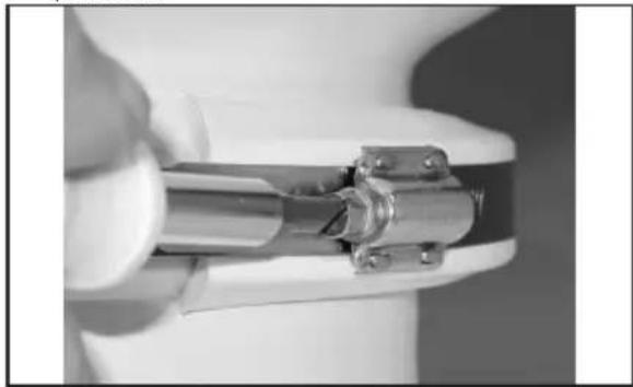
9. Loosening the compression band
a. Loosen the compression band just enough to slip it down past the lower plastic clamp.
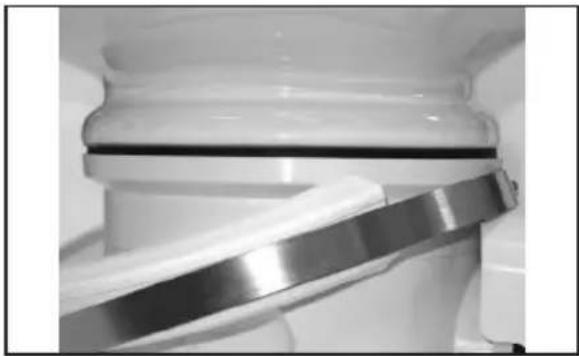
10. Removing the plastic clamps
b. Remove the upper and lower plastic clamps.
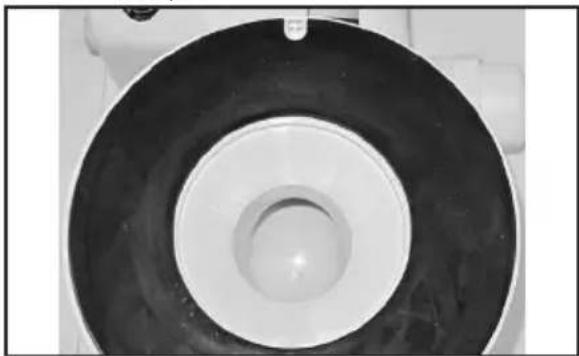
11. Positioning the gasket
c. Lift the bowl. Make sure the notch in the black rubber gasket sits around the shallow pin on the toilet base and remains centered between the bowl and base. d. Rotate the bowl to the desired position, then set it down on the gasket. e. Re-position the plastic clamps and compression band between the upper bowl and base. f. Join the clamps together at the front of the toilet bowl. There will be a space between the clamps behind the bowl. g. With the compression band screw positioned on a clamp (not in the gap between clamps), tighten the compression band to 65 in-lbs (7.3 N-m).
- Connect the water supply hose between the check valve or adapter and the water valve (freshwater flush model) or the water pump (sea water flush model) on the base. See Figure 2.
a. Cut the supply hose to a length that will not kink when connected. b. Remove the plastic cover from the pump. See Figure 2.

12. Tightening the hose clamp
c. Use the hose clamp to secure the hose to the water valve (freshwater model) or pump (sea water model) barbed fitting. d. Place the loose end of the supply hose up through the hole of the plastic cover. e. Lower and fit the cover to the macerator pump.
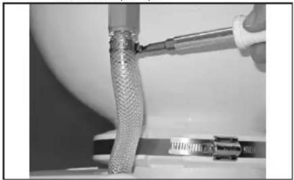
13. Connecting the water supply hose
f. Connect the water supply hose to the rim flush check valve with the hose clamp.
- Plan the electrical, water supply, and discharge plumbing according to the appropriate toilet system layout. See "Toilet system layouts" on page 7.
- Create access holes for the plumbing and electrical supplies to the toilet.
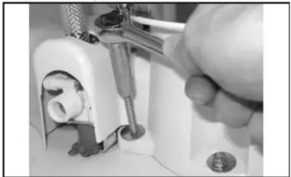
14 Fastening the toilet to the floor
- Place the toilet in its final location and fasten it to the floor with hex head fasteners and washers at the sides and rear of the base.
- Plan the flush switch location so that the electrical connections and wires cannot get wet.
- Use the switch template (packed separately) to mark the location of the fasteners and switch access hole.
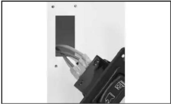
15 Switch access hole
- Cut out the switch access hole.
- Turn off the electrical power.
- Route the stranded copper positive wire (gauge per ABYC standards) from the circuit breaker or fuse to the switch access hole.
- If the toilet system includes a DTM series tank monitor system, see "Toilet system with tank monitor and shut-down relay" on page 13.
Refer to the wiring diagram on the reverse side of the parts list.
- Route the red wire from the macerator pump to the switch access hole.
- Route the wire from the switch access hole to the electric water valve at the bottom of the toilet (freshwater model).
- Connect the wires according to the diagram with the appropriate spade connectors.
- Attach the flush switch to the wall with the screws provided.
- Connect the ground wires from the macerator pump and the electric water valve (freshwater models only) to the vessel's electrical ground wiring according to the wiring diagram. Provide extra wire at the toilet so that the toilet can easily be removed from the floor for servicing.
- Route the vessel's water supply and the discharge plumbing to the toilet. See "Toilet system layouts" on page 7.
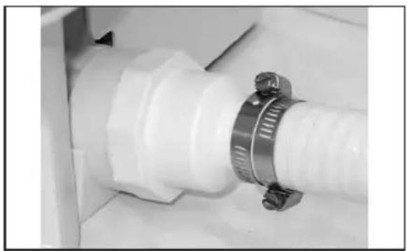
16 Hose clamps on discharge hose
- Securely connect all the discharge hoses with two stainless steel hose clamps with the screws positioned 180 degrees opposite each other.
- Lubricate the fittings and the hoses with silicone grease to make the hose connection easier.
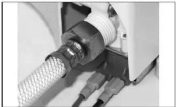
17 Connecting the water supply
- For a freshwater toilet, connect the water supply with a 0.5 in. NPT fitting.
NOTICE: Do not operate the toilet with the water supply turned off. Damage to the internal components may occur.
- For a sea water flush model, open the water supply and discharge the seacocks.
- For a freshwater model, turn on the water supply.
- Check for water leaks at all connections.
- Turn on electrical power to toilet.
- Press the flush switch and check for leaks. If a leak occurs, tighten the connection.
- Attach the plastic covers to the floor mounting fasteners.
6.6 Toilet system with tank monitor and shut-down relay
Dometic MasterFlush toilets operate with Dometic DTM tank monitor systems (available separately) to shut down electrical power to the
toilet when the holding tank is full. This prevents overfilling the holding tank. Refer to the toilet system wiring diagram on the parts list.
- Route the input power wire from full tank relay of the DTM panel to the flush switch location.
- Follow the flush switch installation instructions on page 11 beginning at step 10.
7 Disposal
Place the packaging material in the appropriate recycling waste bins, whenever possible. Consult a local recycling center or specialist dealer for details about how to dispose of the product in accordance with all applicable national and local regulations.
Refer to the sections below for information about warranty and warranty support in the US, Canada, and all other regions.
8.1 United States and Canada
LIMITED WARRANTY AVAILABLE AT DOMETIC. COM/EN-US/TERMS-AND-CONDITIONS-CONSUMER/WARRANTY.
IF YOU HAVE QUESTIONS, OR TO OBTAIN A COPY OF THE LIMITED WARRANTY FREE OF CHARGE, CONTACT:
DOMETIC CORPORATION SANITATION CUSTOMER SUPPORT CENTER 13128 STATE ROUTE 226 BIG PRAIRIE, OHIO, USA 44611 1-800-321-9886
8.2 Asia-Pacific (APAC) countries
If the product does not work as it should, please contact your retailer or the manufacturer's branch in your country (see the back of this instruction manual for the web addresses to locate your region or retailer). The warranty applicable to your product is ONE year.
For repair and warranty processing, please include the following documents when you send in the device:
- A copy of the receipt with purchasing date
- A reason for the claim or description of the fault
8.2.1 Australia only
Our goods come with guarantees that cannot be excluded under the Australian Consumer Law. You are entitled to a replacement or refund for a major failure and for compensation for any other reasonably foreseeable loss or damage. You are also entitled to have the goods repaired or replaced if the goods fail to be of acceptable quality and the failure does not amount to a major failure.
8.2.2 New Zealand only
This warranty policy is subject to the conditions and guarantees which are mandatory as implied by the Consumer Guarantees Act 1993 (NZ).
8.2.3 All other regions
The statutory warranty period applies. If the product is defective, please contact the manufacturer's branch in your region or your retailer (see the back of this instruction manual for the web addresses to locate your region or retailer).
For repair and warranty processing, please include the following documents when you send in the device:
A copy of the receipt with purchasing date - A reason for the claim or description of the fault
Note that self-repair or nonprofessional repair can have safety consequences and might void the warranty.
Visit: www.dometic.com.
9 Loosen the compression strap
8.2 Asia-Pacific (APAC) countries
the hose to prevent emptying.
8.2.2 New Zealand only
This warranty policy is subject to the conditions and guarantees that are mandatory as contained in the Consumer Guarantees Act 1993 (NZ).
8.2.3 All other regions
12 Pull the hose compartment
Dometic switch panel for monitoring
(Figure 4 on page 2)
183 mm (3.25 inches) 241 mm (1.625 inches)
5.2 Materials
Dometic switch panel for monitoring
Polystyrene (DFS-1F or DFS-2F); or aluminum (DFST)
5.3 Minimum system requirements
Toilet flush unit (Fig. 2 on page 2)
Toilet with direct discharge overboard (Fig. 7 on page 3)
1 Toilet 2 Ventilated elbow, 25 mm (1.0 in) or 38 mm (1.5 in) 3 Air inlet fitting 4 Flange, internal diameter 25 mm (1.0 in) or 38 mm (1.5 in) 5 Flush unit with shut-off valve 6 Fresh water supply 7 Water inlet, internal diameter 13 mm (0.5 in) 8 Seawater supply 9 Flange, internal diameter 19 mm (0.75 in) 10 Ventilated elbow 19 mm (0.75 in) with check valve 11 Air outlet fitting 12 203 mm (8.0 in) 13 Maximum heel 14 Waterline 15 Static position
Toilet with discharge to holding tank
(Fig. 8 on page 4)
1 Toilet 2 Add ventilated elbow if tank is below waterline 3 Air inlet fitting 4 Discharge pump 5 Air filter 6 Holding tank (in section) 7 Discharge to seacock
6.3 Inlet piping

WARNING: Risk of flooding.
Do not connect the seawater inlet of the toilet to the ship's freshwater system. This will cause constant leakage of water and may cause the toilet bowl to overflow and flood the vessel. Failure to follow this warning may result in death or serious injury.

WARNING: Risk of contamination.
Do not connect the seawater inlet of the toilet to the ship's potable water system. This may lead to contamination of the potable water system. If the toilet
will be used with fresh water, it is necessary to purchase a special version of the toilet designed for fresh water use, or to install a separate fresh water tank exclusively for the toilet water supply. Failure to follow this warning may result in death or serious injury.

Be sure to install a ventilated elbow that will not restrict the supply of the required amount of water to the toilet bowl. It is recommended to use an electromagnetic type.
- Install the toilet and discharge hose to the sanitation hose (not included in the supply set).
Use a full-bore toilet 25 mm (1.0 in) or 38 mm (1.5 in) flexible hose for transporting waste to the holding tank using the discharge pump, or lay
Tighten the discharge pipe directly to the tank. Follow the manufacturer's instructions for installing the hose.
-The discharge hose is located in the feed section above the discharge hose level. -The discharge pipeline must not have sharp edges or restrictions. -Use a hose clamp made of stainless steel at each hose connection. -Install supports along the entire hose to limit lateral movement and load on the connection. -The length of the sections must be checked. Eliminate sagging and low sections that may obstruct flow.
2. Install the elbow of the drain hose next to the tank (not included in the delivery scope).
-To maintain the water level in the tank, make the elbow at a height of 300 mm (12.0 inches) above the tank as close as possible. See "Water Drainage System" on page 169.
- Install a vented elbow (not included in the delivery scope).
-See recommendations for placement of the vented elbow relative to system components located below the waterline, especially at heights less than 203 mm (8.0 inches) above the maximum water level at extreme heel, in Fig. 7 and Fig. 8. -The vented elbow must be located at least 203 mm (8.0 inches) above the maximum possible water level at extreme heel.
6.5 Tank and drain valve
- Carefully unpack the tank, water supply hose, drain fitting, and fasteners. See Fig. 1.
- Place the tank in the desired location on the floor. If necessary, turn the tank so that the pump housing
The grinder does not touch the wall or to fit it into the existing piping layout. See Fig. 2.
3. Verify that there is sufficient free space for connecting the pipes, as well as access to the lid for maintenance. 4. Mark the location for the tank installation on the floor. 5. (Optional) If the pump and base need to be installed on a pedestal so that the tank outlet is not turned in the wrong direction, turn the upper part.
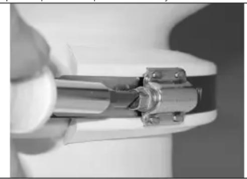
9 Loosening the banding strap
a. Loosen the banding strap just enough to slide the strap below the lower plastic clamp.

10 Removing the plastic clamps
b. Remove the upper and lower plastic clamps.
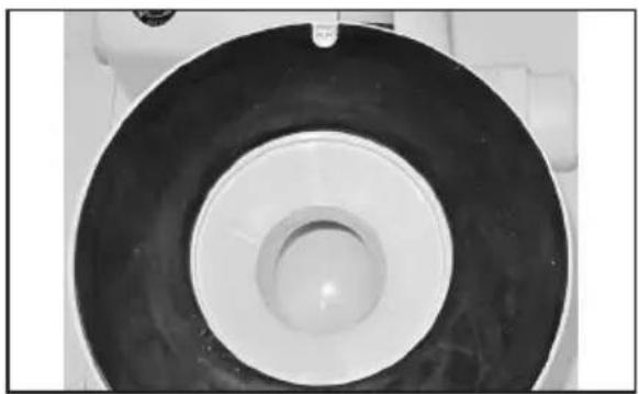
11 Installation of the base
c. Lift the unit and make sure that the recess in the rubber gasket is fitted onto the small flange at the base of the unit and is centered between the base flanges. d. Turn the unit to the required position, then install it on the gasket. e. Place the plastic clamps on the bandage tape between the upper unit and the base. f. Connect the clamps to each other in the front part of the unit. There will be free space between the clamps at the rear of the unit. g. With the bandage tape located on the clamp (not in the gap between the clamps), tighten the bandage tape with a torque of 7.3 N·m (65 pound-inches).
6. Connect the water supply hose between the check valve or adapter and the water valve (models for fresh water) or the water pump (models for sea water) at the base. See Fig. 2.
a. Cut the supply hose to the required length so that it does not twist when connected. b. Remove the plastic cover from the pump. See Fig. 2.
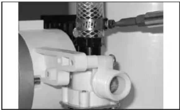
12 Clamp screw
c. Use the clamp screw to secure the hose to the water valve (models for fresh water) or the pump (models for sea water). d. Insert the free end of the hose upward into the hole in the plastic cover. e. Lower and install the cover on the pump and the strainer.
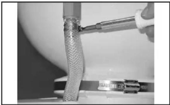
13 Connection of the water supply hose
f. Connect the new water supply hose to the check valve on the left side using the clamp.
- Make the electrical system, water supply system, and drainage system according to the requirements for the arrangement of components. See "System Diagrams" on page 169.
- Make openings for access to the pipes and electrical wiring of the unit.
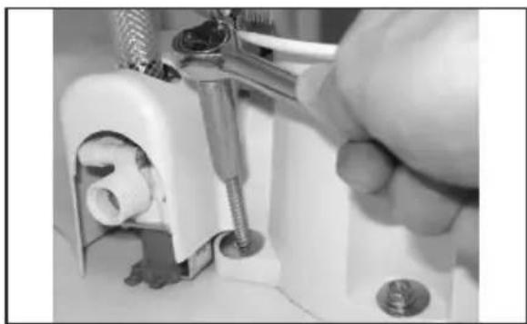
14 Securing the unit to the floor
9. Install the unit in its final position and secure it to the floor with fasteners with hex heads and washers on the sides and rear of the base. 10. Determine the position of the drain valve so that water does not splash on electrical connections or wires. 11. Use the valve template (packed separately) to mark the location of the drain and the opening for access to the valve.
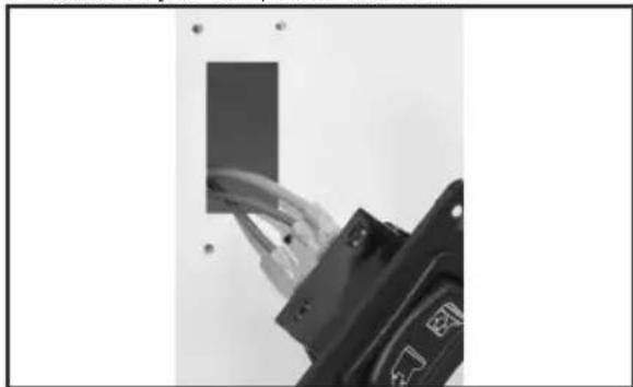
15 Opening for access to the valve
- Cut out the opening for access to the valve.
- Disconnect the electrical power.
- Power supply cable (according to ABYC standards) for automatic switch-off protection against access to the switch.
If the toilet system includes monitoring of the holding tank and a shut-off relay, see "Toilet System with Holding Tank Monitoring and Shut-off Relay" on page 176.
See the wiring diagram on the back of the spare parts list.
- Route the cable from the pump to the access opening to the switch. 16. Route the cable from the access opening to the switch to the electric water valve in the lower part of the toilet (model for freshwater). 17. Connect the cables according to the diagram using the appropriate flat contacts.
- Secure the switch with screws to the wall. 19. Connect the ground cables of the pump, macerator, and electric water valve (only for freshwater models) to the ground terminal according to the diagram. 20. Provide cable slack so that the toilet can be easily disconnected for servicing.
- Route the water supply hose from the sink to the toilet. See "Toilet System Diagrams" on page 169.
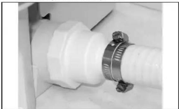
16 Hose clamp, left side
- Securely connect all hoses on the left side with two stainless steel clamps using screws positioned 180 degrees apart. 22. Lubricate the hose fittings with silicone grease to facilitate connection.
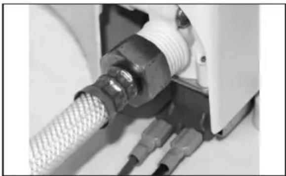
17 Connection to the water supply system
23. For freshwater models, connect the water supply using a 0.5-inch hose fitting.
NOTE: Do not use the toilet with the water supply disconnected. This
may cause damage to internal components.
24. For seawater models, open the water supply valve and follow the instructions. 25. For freshwater models, turn on the water supply. 26. Check all connections for leaks. 27. Turn on the toilet's electrical power. 28. Press the flush switch and check for leaks. If leaks are found, tighten the connections. 29. Attach the plastic covers with the provided screws.
6.6 Toilet System with Holding Tank Monitoring and Shut-off Relay
The Dometic MasterFlush toilet uses the DometicDTM monitoring system (supplied separately) to shut off the electric flush when the holding tank is full. This prevents overflow. See the wiring diagram in the spare parts section.
- Connect the input power cable from the battery charging source to the location of the switch.
- Follow the installation instructions for the switch on page 173, starting from step 10.
7 Disposal
If possible, recycle the material. Dispose of waste at the recycling center or through the trade network in accordance with the relevant national regulations.
dometic.com/sales-offices