MMX24USB - Mixer IMG STAGE LINE - Free user manual and instructions
Find the device manual for free MMX24USB IMG STAGE LINE in PDF.
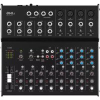
| Product type | Mixing console |
| Brand | IMG STAGE LINE |
| Model | MMX24USB |
| Mono input channels | 2 |
| Stereo input channels | 4 |
| Microphone input sensitivity | 0.5 mV |
| Line input sensitivity (mono) | 1 mV |
| Line input sensitivity (stereo) | 10 mV |
| Tape In input sensitivity | 100 mV |
| Master Out/Tape Out output level | 650 mV (for 0 dB indication) |
| Booth Out output level | 2 V (for 0 dB indication) |
| Aux Send output level | 9.5 V max |
| Headphone impedance | ≥ 8 Ω |
| Distortion rate | < 0.05 % |
| Signal-to-noise ratio | > 74 dB (A weighted) |
| Equalizer | Bass ±15 dB/80 Hz, Mid ±15 dB/2.5 kHz, Treble ±15 dB/12 kHz |
| Low Cut filter | 75 Hz |
| Phantom power | +48 V |
| Power supply | 18 V via power adapter (230 V/50 Hz) |
| Dimensions (W × H × D) | 220 × 65 × 260 mm |
| Weight | 2.1 kg |
| USB audio interface | Yes (USB type B port) |
| Operating temperature | 0 - 40 °C |
| Compatible operating systems | Windows 2000/XP or later, Mac OS 9.0.4 or higher, Mac OS X |
| Use | Indoor only |
| Cleaning | Dry soft cloth, no chemicals |
| Safety | Do not open the housing. Disconnect if damaged. Avoid moisture and water splashes. |
| Repairability | Repair by qualified technician only |
Frequently Asked Questions - MMX24USB IMG STAGE LINE
User questions about MMX24USB IMG STAGE LINE
0 question about this device. Answer the ones you know or ask your own.
Ask a new question about this device
Download the instructions for your Mixer in PDF format for free! Find your manual MMX24USB - IMG STAGE LINE and take your electronic device back in hand. On this page are published all the documents necessary for the use of your device. MMX24USB by IMG STAGE LINE.
USER MANUAL MMX24USB IMG STAGE LINE
These operating instructions are intended for users with basic knowledge in audio technology. Please read the instructions carefully prior to operation and keep them for later reference.
All operating elements and connections described can be found on the fold-out page 3.
1 Operating Elements and Connections
The figures on page 3 show model MMX-24USB. Model MMX-44, equipped with two additional mono input channels, features the same operating elements and connections except for the USB interface and the corresponding additional functions for USB operation.
1.1 Front panel
Figure 1 shows the example of a mono channel and a stereo channel; the other input channels are identical.
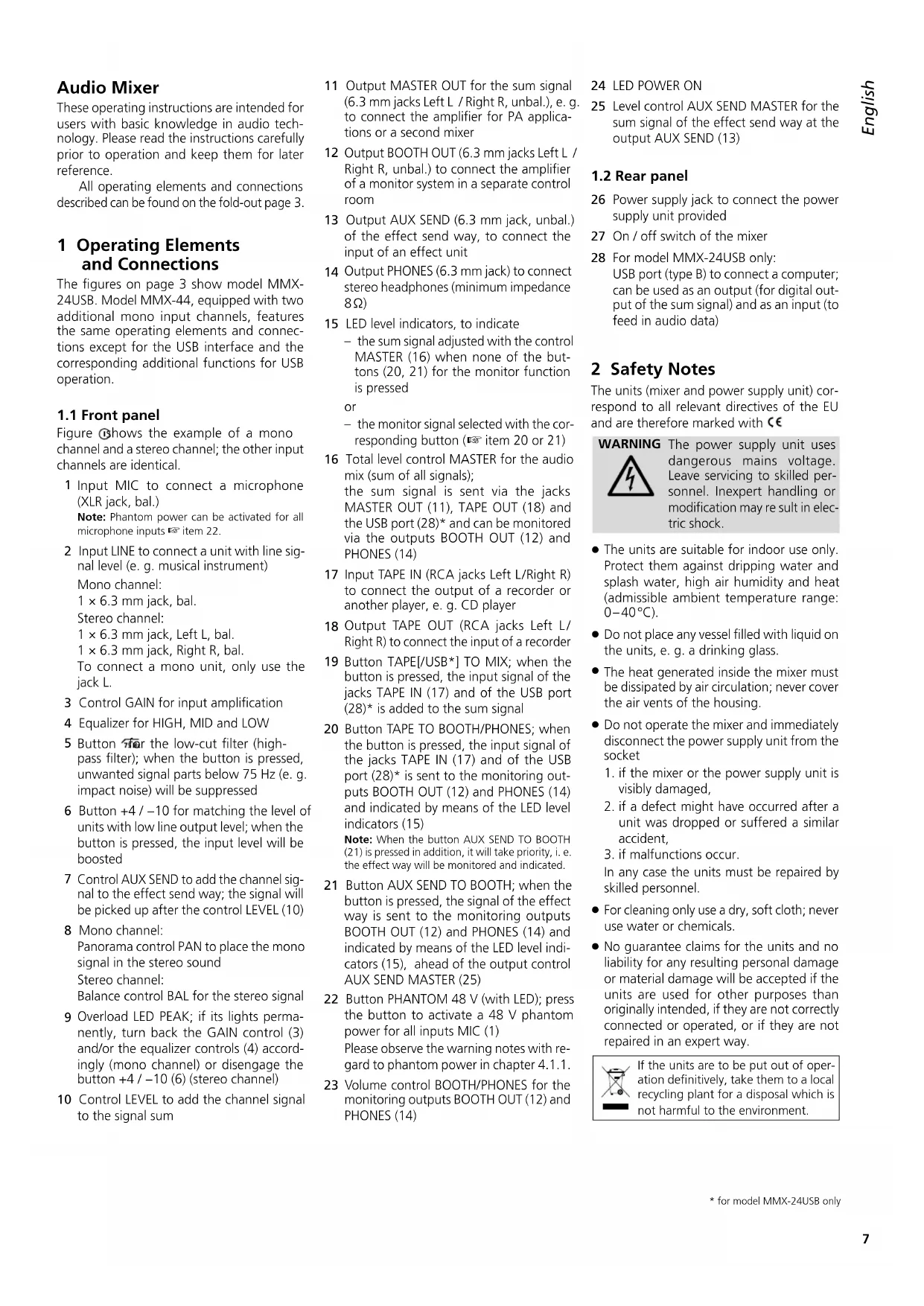
1 Input MIC to connect a microphone (XLR jack, bal.)
Note: Phantom power can be activated for all microphone inputs item 22.
2 Input LINE to connect a unit with line signal level (e.g. musical instrument)
Mono channel:
1 × 6.3 ~mm jack, bal.
Stereo channel:
1× 6.3mm jack,Left L,bal.
1 × 6.3 mm jack, Right R, bal.
To connect a mono unit, only use the jack L.
3 Control GAIN for input amplification
4 Equalizer for HIGH, MID and LOW
5 Button for the low-cut filter (high-pass filter); when the button is pressed, unwanted signal parts below 75Hz (e.g. impact noise) will be suppressed
6 Button +4 / - 10 for matching the level of units with low line output level; when the button is pressed, the input level will be boosted
7 Control AUX SEND to add the channel signal to the effect send way; the signal will be picked up after the control LEVEL (10)
8 Mono channel: Panorama control PAN to place the mono signal in the stereo sound
Stereo channel:
Balance control BAL for the stereo signal
9 Overload LED PEAK; if its lights permanently, turn back the GAIN control (3) and/or the equalizer controls (4) accordingly (mono channel) or disengage the button +4 / - 10 6)(stereo channel)
10 Control LEVEL to add the channel signal to the signal sum
11 Output MASTER OUT for the sum signal (6.3 mm jacks Left L / Right R, unbal.), e.g. to connect the amplifier for PA applications or a second mixer
12 Output BOOTH OUT (6.3 mm jacks Left L / Right R, unbal.) to connect the amplifier of a monitor system in a separate control room
13 Output AUX SEND (6.3 mm jack, unbal.) of the effect send way, to connect the input of an effect unit
14 Output PHONES (6.3 mm jack) to connect stereo headphones (minimum impedance 8Ω)
15 LED level indicators, to indicate the sum signal adjusted with the control MASTER (16) when none of the buttons (20, 21) for the monitor function is pressed
or
- the monitor signal selected with the corresponding button (item 20 or 21)
16 Total level control MASTER for the audio mix (sum of all signals);
the sum signal is sent via the jacks MASTER OUT (11), TAPE OUT (18) and the USB port (28)^ and can be monitored via the outputs BOOTH OUT (12) and PHONES (14)
17 Input TAPE IN (RCA jacks Left L/Right R) to connect the output of a recorder or another player, e. g. CD player
18 Output TAPE OUT (RCA jacks Left L/Right R) to connect the input of a recorder
19 Button TAPE[USB*] TO MIX; when the button is pressed, the input signal of the jacks TAPE IN (17) and of the USB port (28)^ is added to the sum signal
20 Button TAPE TO BOOTH/PHONES; when the button is pressed, the input signal of the jacks TAPE IN (17) and of the USB port (28)^ is sent to the monitoring outputs BOOTH OUT (12) and PHONES (14) and indicated by means of the LED level indicators (15)
Note: When the button AUX SEND TO BOOTH (21) is pressed in addition, it will take priority, i.e. the effect way will be monitored and indicated.
21 Button AUX SEND TO BOOTH; when the button is pressed, the signal of the effect way is sent to the monitoring outputs BOOTH OUT (12) and PHONES (14) and indicated by means of the LED level indicators (15), ahead of the output control AUX SEND MASTER (25)
22 Button PHANTOM 48 V (with LED); press the button to activate a 48V phantom power for all inputs MIC (1)
Please observe the warning notes with regard to phantom power in chapter 4.1.1.
23 Volume control BOOTH/PHONES for the monitoring outputs BOOTH OUT (12) and PHONES (14)
24 LED POWER ON
25 Level control AUX SEND MASTER for the sum signal of the effect send way at the output AUX SEND (13)
1.2 Rear panel
26 Power supply jack to connect the power supply unit provided
27 On/off switch of the mixer
28 For model MMX-24USB only: USB port (type B) to connect a computer; can be used as an output (for digital output of the sum signal) and as an input (to feed in audio data)
2 Safety Notes
The units (mixer and power supply unit) correspond to all relevant directives of the EU and are therefore marked with
WARNING
The power supply unit uses dangerous mains voltage. Leave servicing to skilled personnel. Inexpert handling or modification may re sult in electric shock.
- The units are suitable for indoor use only. Protect them against dripping water and splash water, high air humidity and heat (admissible ambient temperature range: 0 - 40^ ).
- Do not place any vessel filled with liquid on the units, e. g. a drinking glass.
- The heat generated inside the mixer must be dissipated by air circulation; never cover the air vents of the housing.
-
Do not operate the mixer and immediately disconnect the power supply unit from the socket
-
if the mixer or the power supply unit is visibly damaged,
- if a defect might have occurred after a unit was dropped or suffered a similar accident,
- if malfunctions occur.
In any case the units must be repaired by skilled personnel.
- For cleaning only use a dry, soft cloth; never use water or chemicals.
- No guarantee claims for the units and no liability for any resulting personal damage or material damage will be accepted if the units are used for other purposes than originally intended, if they are not correctly connected or operated, or if they are not repaired in an expert way.

If the units are to be put out of operation definitively, take them to a local recycling plant for a disposal which is not harmful to the environment.
3 Applications
This audio mixer is designed for universal PA and recording applications. It features 2 (MMX-24USB) or 4 (MMX-44) mono input channels and 4 stereo input channels to connect microphones (also phantom-powered microphones) and audio sources with line output level (e.g. musical instruments, players). A send way allows for use of an effect unit. In addition, connections for a recorder are available. Audio mixing can be monitored by means of headphones and / or a monitor system in a separate control room.
Model MMX-24USB additionally features a USB audio interface to connect a computer.
4 Before Operation
Prior to connecting / disconnecting and prior to switching on, always set the output controls BOOTH / PHONES (23) and MASTER (16) to minimum.
4.1 Connecting audio sources
Since it is not possible to switch over between the inputs in the mono channels, either use the microphone input (1) or the line input (2); never use both inputs at the same time.
4.1.1 Microphones
Connect microphones to the balanced XLR jacks MIC (1). For phantom-powered microphones, press the button PHANTOM 48 V (22) to activate a joint 48 V phantom power for all XLR jacks. When the phantom power has been activated, the LED next to the button will light up.
Caution: When the phantom power has been activated, do not connect any microphone with unbalanced output; it may be damaged.
To prevent switching noise in the speakers and the headphones, only activate or deactivate the phantom power when the mixer has been switched off or when the corresponding output controls have been set to minimum.
4.1.2 Line audio sources
Connect audio sources with line signal level (e.g. receivers of wireless microphone systems, effect units, musical instruments, players) to the 6.3mm jacks LINE (2) of the input channels. The jacks are balanced. However, to connect units with unbalanced output, use 2-pole 6.3mm plugs.
- Connect mono units to the mono channels CH 1 and CH 2 (MMX-24USB) or CH 1 to CH 4 (MMX-44).
- Connect stereo units to the stereo channels CH 3/4 to CH 9/10 (MMX-24USB) or CH 5/6 to CH 11/12 (MMX-44). To connect a mono
unit to a stereo channel, only use the jack L; the mono signal will then internally be sent to the right and the left channels.
If no recorder is connected to the RCA input TAPE IN (17) (chapter 4.3), this input is available for an additional stereo unit with line level (e.g. a CD player for background music during intervals).
4.2 Connecting an effect unit
Via the send way, signal parts can be decoupled from the input channels, routed via an effect unit and then, after being processed, added to the sum signal. The signal will be picked up after the control LEVEL (10) of the corresponding input channel.
1) Connect the input of the effect unit via a 6.3mm plug to the mono output AUX SEND (13).
2) Connect the output of the effect unit to the LINE input (2) of an input channel not used, please refer to chapter 4.1.2.
4.3 Connecting a recorder
A stereo recorder, e. g. a tape recorder, can be connected to the RCA jacks TAPE IN (17) and TAPE OUT (18):
1) Connect the reproduction output of the recorder to the input TAPE IN.
2) Connect the recording input of the recorder to the output TAPE OUT; the output will receive the sum signal adjusted with the control MASTER (16).
The RCA jacks can also be used for other units with line signal level; it is, for example, possible to connect a player (e.g. CD player or MP3 player) to TAPE IN or an additional amplifier to TAPE OUT.
4.4 Connecting a monitor system and headphones
The audio mix, the input signal of the jacks TAPE IN (17) and of the USB port (28)^* or the effect way can be monitored via stereo headphones and / or a monitor system in a separate control room. Connect the headphones (minimum im pedance 8 to the 6.3mm jack PHONES (14). Connect the amplifier of the monitor system to the stereo output BOOTH OUT (12); the two 6.3mm jacks of the output are unbalanced.
4.5 Connecting an amplifier
The stereo output MASTER OUT (11) receives the sum signal adjusted with the control MASTER (16). At this output, the amplifier for PA applications can be connected (or another unit with line input, e.g. a second mixer). The 6.3mm jacks are unbalanced.
4.6 Power supply/
Switching on and off
Connect the power supply unit provided to the power supply jack (26) on the rear panel and to a mains socket (230V / 50Hz)
To switch on the mixer, set the POWER switch (27) to ON; to switch it off, set the switch to OFF. When the mixer is switched on, the power LED (24) will light up.
Note: Always disconnect the power supply unit from the socket when the mixer is not in use for a longer period of time; even when the mixer has been switched off, the power supply unit will consume some power.
4.7 Operation with a computer*
Via the USB port (28), audio data can be transferred in both directions between the mixer and the computer, even at the same time:
- When the USB port is used as an input, data fed in via the USB port can be added to the sum signal and monitored via headphones/monitor system in a control room.
- When the USB port is used as an output, the USB port provides the sum signal adjusted with the control MASTER (16).
To operate the mixer with a computer, either use the audio software supplied with the operating system or audio software installed additionally. Various audio software programs for recording and reproduction are available on the Internet free of charge.
1) Start the computer and connect the USB port of the mixer to a USB connection on the computer.
2) The computer will recognize the switched-on mixer as a USB audio device for audio input and audio output. The required drivers (de fault drivers of the operating system) are available on the computer.
Note: If not all drivers required are available on the computer, install them, e. g. by means of the original CD of the operating system. If necessary, restart the computer after installing the drivers.
3) Call up the audio program used, make the settings required for audio reproduction via the mixer or audio recording from the mixer (135 manual of the program). The mixer can then be operated as described in chapter 5.
If no audio recording or audio reproduction is possible, check the system settings of the computer to find out if the USB interface has been selected for audio input or audio output.
Hint: If the mixer is connected to both a computer and to units earthed via their mains cable (e.g. amplifiers), hum interference may occur due to ground loops. To eliminate this interference, use a ground isolator (e.g. FGA-102 or FGA-202 from IMG STAGELINE) to connect the mixer to the corresponding unit.
5 Operation
CAUTION

Never adjust the audio system or the headphones to a very high volume. Permanent high volumes may damage your hearing! Your ear will get
accustomed to high volumes which do not seem to be that high any more after some time. Therefore, do not further increase a high volume after getting used to it.
5.1 Basic adjustments of the input channels
The following steps for level matching and sound correction, are merely an aid; other procedures are possible.
1) In all input channels, turn back the controls LEVEL (10) to the left stop.
In the mono input channels, set all controls GAIN (3), all controls EQ (4) and all controls PAN (8) to mid-position and disengage all buttons.
In the stereo input channels, disengage all buttons +4 / - 10 (6) and set all controls BAL8 to mid-position.
2) Turn back the control AUX SEND MASTER (25) to the left stop.
3) Disengage the buttons TAPE [/ USB*] TO MIX (19), TAPE TO BOOTH / PHONES (20) and AUX SEND TO BOOTH (21).
4) Set the control MASTER (16) to "0 dB".
5) Feed an audio signal to the corresponding input channel (e.g. sing into a microphone, play a musical instrument).
6) To adjust a mono channel, set the control LEVEL (10) to mid-position. Adjust the control GAIN (3) so that the LED level indicators (15) light up at 0 dB. Use the three EQ controls (4) to adjust the sound. If required, press the button
to suppress low-frequency interference (e.g. impact noise, hum). Then, if necessary, use the control GAIN to readjust the level adjustment. The LED PEAK (9) should briefly flash for signal peaks only. If it lights permanently, turn back the control GAIN and / or the equalizer controls accordingly. To adjust a stereo channel,
turn up the control LEVEL (10) so that the LED level indicators (15) light up at 0 dB. If you have to turn up the control considerably, press the button +4 / -10 (6) to boost the level (12 dB) for the channel. If you have to turn back the control considerably and the LED PEAK (9) of the channel lights permanently, attenuate the output level of the audio source.
7) After adjusting a channel, turn back its control LEVEL to the left stop, and then adjust the next channel.
5.2 Mixing audio sources
1) Slide up the control MASTER (16) so that the mixing ratio of the audio sources can be adjusted in an optimum way.
2) When all level matching adjustments and all sound adjustments have been made (10) to mix the signals of the input channels in the volume ratio desired. Always turn the controls LEVEL of the channels not used back to the left stop.
3) For the mono channels, use the panorama controls PAN (8) to place the mono signals in the stereo sound. For the stereo channels, use the controls BAL (8) to adjust the balance of the stereo signals.
4) When an effect unit has been connected, please refer to chapter 5.2.1.
5) To add the input signal of the jacks TAPE IN (17) and of the USB port (28) to the signal sum, press the button TAPE [/USB] TO MIX (19).
Note: If, during recording via the jacks TAPE OUT or the USB port, the recording signal is sent as an input signal to the jacks TAPE IN or to the USB port, make sure that the button TAPE [/ USB*] TO MIX is disengaged; otherwise, there will be feedback.
6) Use the control MASTER (16) to adjust the definitive volume of the sum signal; check the LED level indicators (15) while adjusting the volume. Make sure that the two buttons (20, 21) for the monitor function are disengaged; otherwise, the LED level indicators will not indicate the level of the sum signal. In case of overload, the red LEDs CLIP of the level indicators will light up.
5.2.1 Adjusting the effect send way
Connect the effect unit to the output AUX SEND (13) and to the LINE input (2) of an input channel not used.
1) To make sure that the subsequent effect adjustments are audible, first set the following controls approximately to mid-position:
-AUX SEND MASTER (25)
- the control LEVEL (10) of the channel to which the effect unit has been connected
2) Use the controls AUX SEND (7) to add the signals of the input channels to the effect way. The signal will be picked up after the control LEVEL (10), i.e. the effect part of a channel is always proportional to the channel level adjusted.
Note: Turn back the control AUX SEND of the channel to which the effect unit has been connected to the left stop; otherwise, there will be feedback.
3) Use the control AUX SEND MASTER (25) to adjust the level for the output signal of the effect way (sum of all signals added to the effect way) so that the effect unit will not be overloaded.
4) Use the control LEVEL (10) of the channel to which the effect unit has been connected to add the effect signal to the sum signal.
5.3 Monitoring via headphones and monitor system
The two assign buttons (20, 21) for the monitor function define which signal will be monitored via the outputs BOOTH OUT (12) and PHONES (14) and indicated by the LED level indicators (15):
If none of the buttons is pressed, the sum signal adjusted with the control MASTER (16) will be monitored and indicated.
If only the button TAPE TO BOOTH / PHONES (20) is pressed, the input signal of the jacks TAPE IN (17) and of the USB port (28)^* will be monitored and indicated (e. g. to check a recording).
- If the button AUX SEND TO BOOTH (21) is pressed, the signal of the effect way will be monitored and indicated, ahead of the output control AUX SEND MASTER (25). In this case, the position of the button TAPE TO BOOTH / PHONES is irrelevant.
Use the control BOOTH / PHONES (23) to adjust the monitoring volume.
6 Specifications
Input sensitivity
Mic: 0.5mV
Line (mono channel): .1mV
Line (stereo channel): 10mV
Tape In: 100mV
Output level
Master Out/Tape Out: 650mV (at indication 0 dB)
Booth Out: 2V (at indication 0 dB)
Aux Send: 9.5 V max.
Headphone impedance: ≥ 8
USB interface*: . USB 2.0 (Full Speed)
Frequency range: 20-20000 Hz
THD: < 0.05%
S/N ratio: >74 dB (A weighted)
Crosstalk: -63 dB
Equalizer controls
LOW: ±15dB/80Hz
MID: ±15dB/2.5kHz
HIGH: .±15dB/12kHz
Low-cut filter: 75 Hz
Phantom power: . . . . +48 V
Power supply: 18V via power
supply unit provided, connected to 230V / 50Hz
Ambient temperature: 0 - 40^
Dimensions (W× H× D)
MMX-24USB: .220 × 65 × 260 mm
MMX-44: 280 × 50 × 260 mm
Weight
MMX-24USB: 2.1 kg
MMX-44: 2.2 kg
Suitable operating systems for data transfer via USB interface*: Windows 2000, Windows XP or subsequent Windows versions, Mac OS 9.0.4 or later, Mac OS X
Windows is a registered trademark of Microsoft Corporation in the USA and other countries. Mac OS is a registered trademark of Apple Inc. in the USA and other countries.
Subject to technical modification.
Table de mixage audio
4.6 Alimentation/ Marche/arret
Interface USB* USB 2.0 (Full Speed)
Bande passante: 20-20000 Hz
USB-interface*: USB 2.0 (Full Speed)
Frequentiebereik: .20-20 000 Hz
THD: < 0.05%
Signaal/Ruis
Low Cut-filter: 75 Hz
Interfaz USB*: USB 2.0 (Full Speed)