G X56 Hotas - Game controller LOGITECH - Free user manual and instructions
Find the device manual for free G X56 Hotas LOGITECH in PDF.
| Product type | Game controller (joystick + throttle) |
| Brand | Logitech G |
| Model | G X56 Hotas |
| Main functions | Flight control with stick and throttle, programmable axes (X, Y, Rz, rudder), dual throttles with lock, analog mini-stick, HAT switches, switches and rotary controls, interchangeable F.E.E.L. spring system |
| Software | Logitech G HUB programming software (download at logitech.com/support/x56) to create profiles, adjust response curves and dead zones |
| Power supply | USB (via PC) |
| Operating systems | Windows 7, 8, 10 |
| Minimum configuration | .NET Framework required |
| Programmable axes | Stick: X, Y, rudder axes; Throttle: left/right throttle, 4 rotary controls |
| Interchangeable springs | 4 springs (red, yellow, blue, green) offering different tensions |
| Physical adjustments | Throttle tension adjuster, dual throttle lock |
| Lighting | RGB (brightness and colors adjustable via software) |
| Maintenance | Spring replacement possible; unplug USB before working on the stick |
| Safety | Unplug the USB cable before handling internal connectors |
| Spare parts | Replacement springs available (red, green, yellow, blue) |
| Compatibility | PC with USB ports |
Frequently Asked Questions - G X56 Hotas LOGITECH
User questions about G X56 Hotas LOGITECH
0 question about this device. Answer the ones you know or ask your own.
Ask a new question about this device
Download the instructions for your Game controller in PDF format for free! Find your manual G X56 Hotas - LOGITECH and take your electronic device back in hand. On this page are published all the documents necessary for the use of your device. G X56 Hotas by LOGITECH.
USER MANUAL G X56 Hotas LOGITECH
HANDS ON THROTTLE AND STICK
SYSTEME 3M
(MAINS SUR MANCHE ET MANETTE)
USER MANUAL / MANUEL DE L'UTILISATEUR
English 3
Espanol. 43
Francais 23
Portugues 63
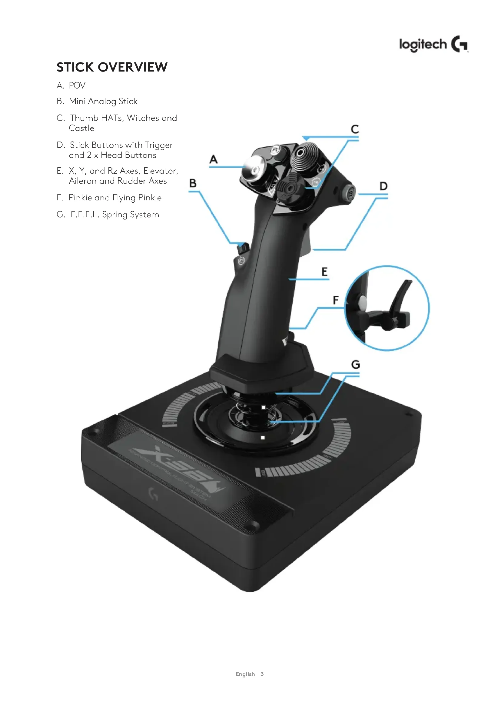
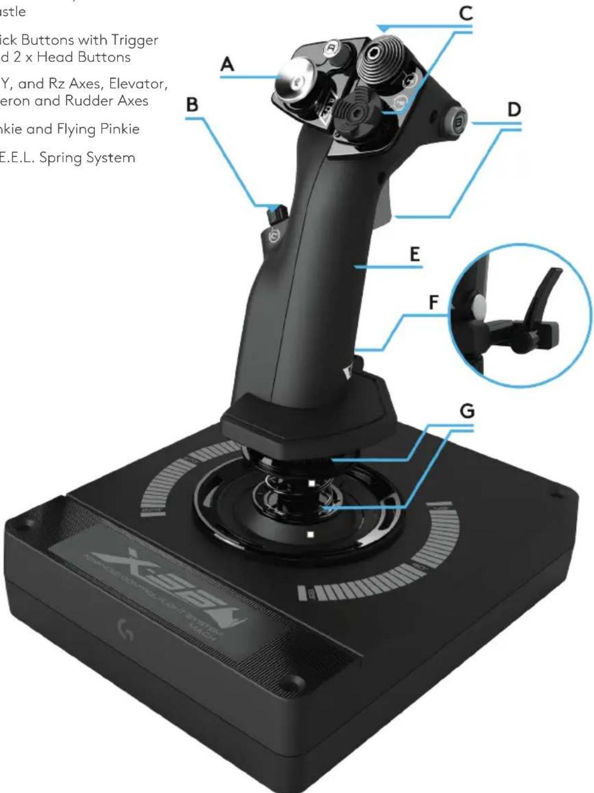
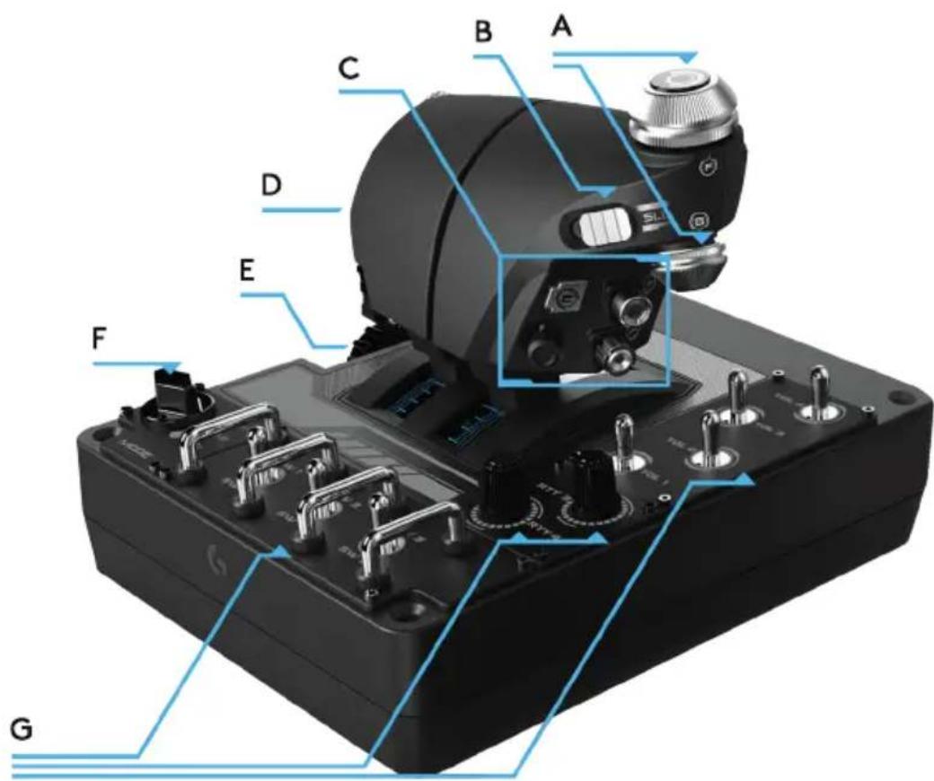
STICK OVERVIEW
A. POV
B. Mini Analog Stick
C. Thumb HATs, Witches and Castle
D. Stick Buttons with Trigger and 2 x Head Buttons
E. X, Y, and Rz Axes, Elevator, Aileron and Rudder Axes
F. Pinkie and Flying Pinkie
G. F.E.E.L. Spring System
THROTTLE OVERVIEW
A. Throttle Rotaries with inset buttons
B. 2-position Slider
C. Thumb Controls with 2 HATs, Thumb Button, Mini AnalogStick
D. Twin Throttles with Throttle Lock
E. Throttle Tension Adjuster
F. 3-position Mode Switch
G. Base Controls with 7 Toggles and 2 Rotaries
GETTING STARTED
Drivers and Software Installation
Windows® 7/8/10
- Download and install the X56 HOTAS software from logitech.com/support/x56
- After reading the Disclaimer, select the 'I accept the terms of the Disclaimer' option and click 'NEXT' to continue
- At the Plug In screen, plug the Stick and Throttle units into the PC. Click 'Next' when it becomes highlighted
- From the end screen, click 'Finish.' Your drivers and software are now installed
NET Framework
- If this is the first Logitech product that you have installed, you may be asked to install .NET Framework after the software installation finishes. This is strongly recommended; this Microsoft Feature Update is required by the Software
- Click 'Download and install this file.' The PC will now find the correct files from the Internet and download them
- When the installation finishes, click 'Close'
CONTROLLER SETTINGS
If at any time you wish to check that the X56 is working correctly, open the Game Controllers page and click on the controller's Properties tab.
Here are the various ways to do this from each operating system:
Windows® 8/10
- From the Metro/Start screen, click the 'Control Panel' icon. NOTE: If you have no Control Panel icon on your Metro/Start screen, type 'control panel' and the icon for the Control Panel will appear
- Once the Control Panel is open, double-click on the 'Devices and Printers' icon. NOTE: If you cannot see this icon, make sure that you have large icons selected
- With the Devices and Printers screen open, find the X56 HOTAS in the device list and right-click on this icon. From the dropdown menu, select 'Game Controller Settings'
- From the Game Controllers window, you should see the X56 HOTAS. listed and selected. Click 'Properties' and this should take you to the Controller Test screen
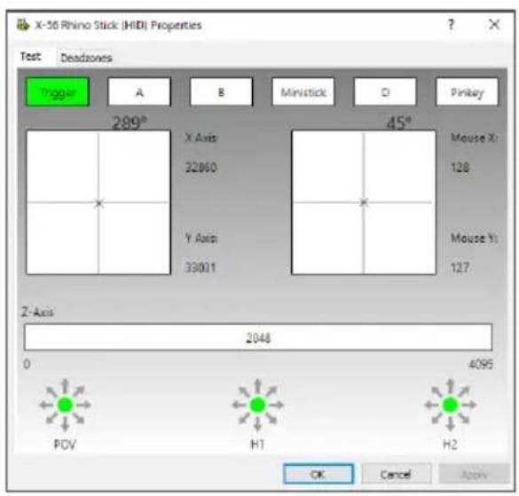
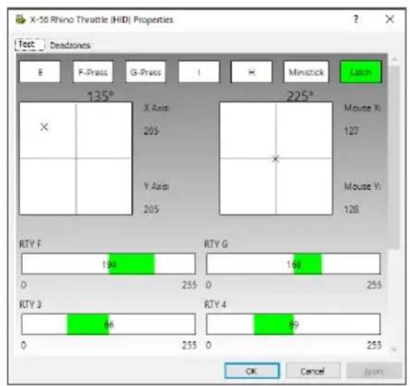
From the Controller Test screen you can test all the functions, axes, buttons, rotaries, etc. When you have completed your tests, click 'OK' twice to get back to the main desktop
Windows® 7
- Click on the 'Windows' icon from the system tray. Hover over the All Programs menu. Click the 'Games' folder and then the 'Games Explorer' icon
- Click the 'Tools' option (with downward facing arrow) from the list across the top of the window. From the dropdown list, click 'Input Devices'
- From the Game Controllers window, you should see the X-56 Rhino listed and selected. Click 'Properties' and this should take you to the Controller Test screen
F.E.E.L. Spring Tension System
Each spring placed on the Rhino stick shaft will give a different feeling. You can also operate the stick without a spring, providing a total of five different forces.
Each spring has a unique feel and different identification. These identifiers are color swatches at the top of each spring - Red, Yellow, Blue, and Green. This table lists some of the calculations used for differentiation:

| RED GREEN YELLOW BLUE Notes | |||||
| k = Rate 1 2 3 4 | |||||
| OD = Outside diameter 33 33 33 33 | |||||
| d = Wire diameter 1.8 1.8 1.8 | 1.8 | ||||
| E = Youngs Modulus ( 210000 ) | 210000 | 210000 | 210000 | 210000 | N/mm2 |
| FL = Free length | 52 | 47 | 42 | 36 | Un-compressed |
| WL = Working length | 30.8 | 30.8 | 30.8 | 30.8 | Pre-compressed |
| P1L = Position 1 length | 25.8 | 25.8 | 25.8 | 25.8 | Full Working Compression |
| n = Total Number of coils | 4.5 | 4.5 | 4.5 | 4.5 | Active coils (6.5 coils in spring) |
| D = Mean Diameter | 31.2 | 31.2 | 31.2 | 31.2 | |
| Rate K= Ed*4/8n D *3 | 1.70 | 1.70 | 1.70 | 1.70 | N/mm |
| Load @ Breakout BL = FL-WL x k | 36.12 | 27.60 | 19.08 | 8.86 | N |
| Load @ P1L SoL = FL - SL x k | 44.64 | 36.12 | 27.60 | 17.38 | N |
| Stress= 8 x P x D/3.14 x d *3 | 608.50 | 492.38 | 376.25 | 236.90 | N/mm2 |
| % UTS ( M4 Music Wire ) | 30.89 | 24.99 | 19.10 | 12.03 | % |
Changing or removing a spring
To insert, change, or remove a spring, follow these steps. Ensure the trigger is facing away from you and that the X56 HOTAS logo plate is facing you.
- Turn the Locking Bezel (part B) counterclockwise until the Stick comes away from the base.
- Remove the Seal Ring (part C) by placing the fingers from your left and right hand under the ring on either side, and then lift up. The Seal Ring is stiff by design.
- Pry apart the Locking Clamps (part D). These pull apart from the stick, but are under load from the spring. Take one half off first, hold the spring, and then remove the other half.
- Remove the Spring (part E), then either replace with a new Spring of leave the Spring off.
To reassemble, reverse the order of the above steps, making sure to securely seat the Seal Ring (Part C) and firmly tighten the Locking Bezel (part D) on the Stick base.
Note: When changing springs, please ensure that the USB cable is disconnected from your PC and avoid touching the connectors in the stick handle and base.
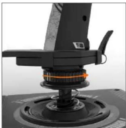
1. Turn Locking Bezel counterclockwise
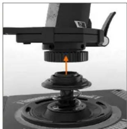
2. Remove Stick
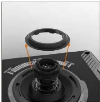
3. Remove Seal Ring
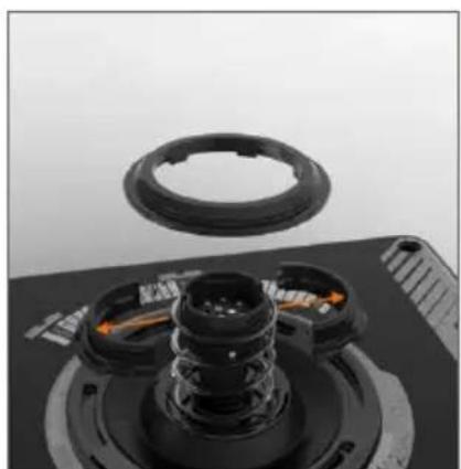
4. Pry apart Locking Clamps
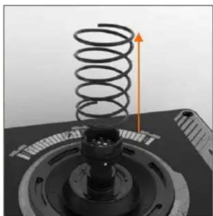
5. Remove Spring
Software Overview
The software allows you to program the X56 with an array of keyboard commands, from basic single-key commands to very advanced, timed, and macro commands. It will also allow you to program any axis with keyboard commands, and program mouse commands.
In the software you can also alter the response curves and deadbands of the main axis - we'll cover the explanation of these topics later in the manual.
There are two ways to launch the software:
- From the desktop icon that looks like this 2. From the start menu bar...
Once the software launches, you will be presented with the Home Screen.
If it's the first time you've run the software, you will be asked to choose your language.
Once this is done the main Home Screen will appear. If you've made a mistake choosing your language or you wish to choose another language, the language menu can be accessed by clicking on the icon in the bottom-right corner of the Home Screen.
There are three main Tabs within the software:
- HOME
2.PROGRAMMING - SETTINGS

HOMETAB

On the Home screen you'll see:
Live Facebook feed from Logitech G
- Social media and website shortcuts, LogitechG.com, Twitter, YouTube, Instagram, etc
- Language selection, use the flag icon in the bottom-right corner to access this
PROGRAMMING TAB
After selecting the PROGRAMMING Tab you will see the X56's programming environment.
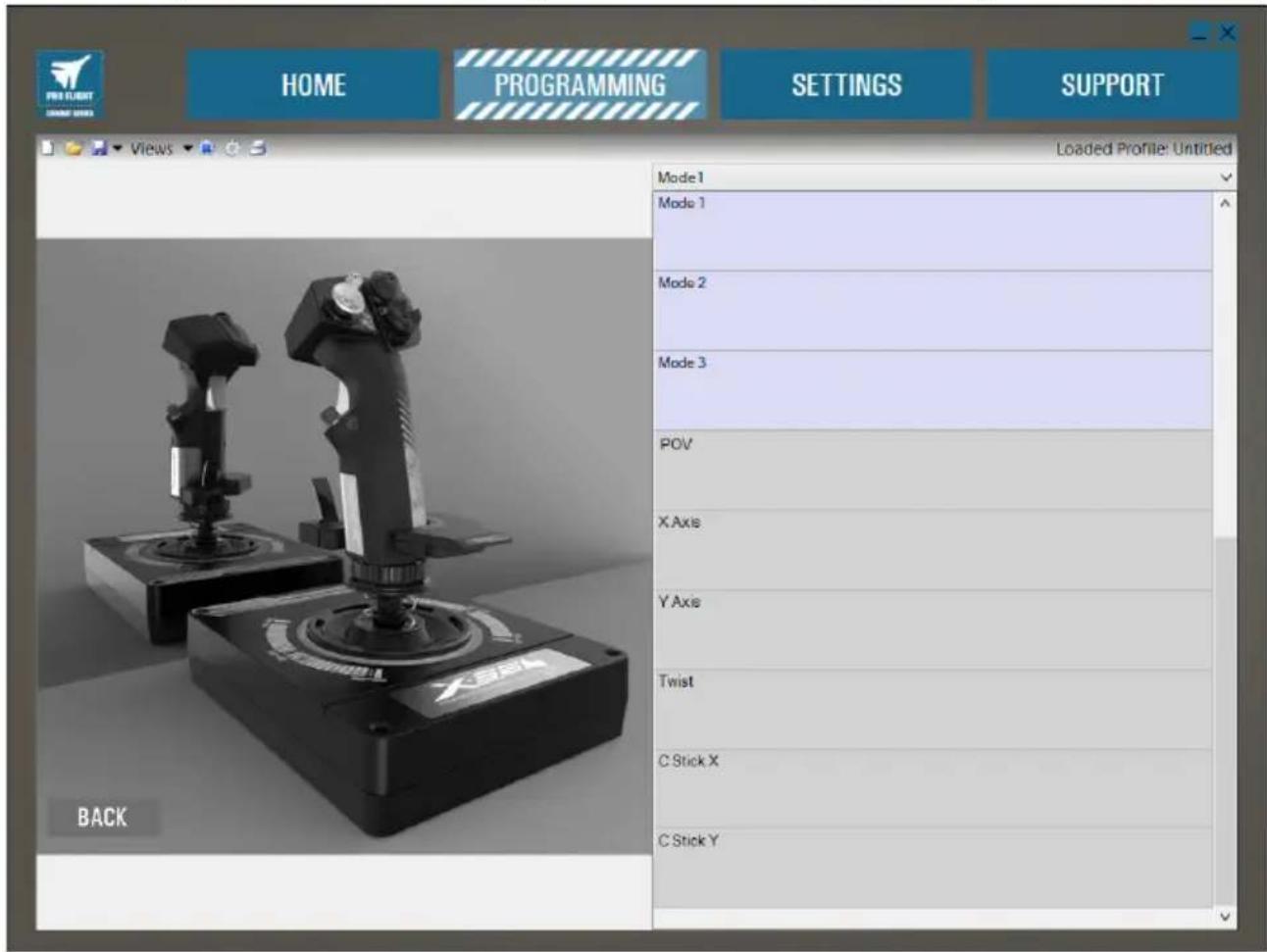
You will see a high-resolution image of the controller you are going to program on the left side of the screen. On the right side of the screen you will see a list of command boxes, called "Cells," going down the page.
At the top of the image panel you will see Stick and Throttle icons. Clicking on either of these will change the current unit you are programming. The unit you are programming is easily recognizable by the larger image that fills the window.
In the PROGRAMMING Tab you can mimic your controller to directly copy any of the keyboard commands used in your favorite games. The commands are then saved in what we call a Profile.
What is a Profile?
A Profile is the name given to a file that has programmed controller commands saved into it. For example, you may have a Joystick with a number of buttons/hats. If you want one of these to do something in-game that you would normally have to use a keyboard shortcut for, you can "assign" that command to that button. If you want Button 'A' to activate the landing gear (which is the "G" key on a keyboard), you can use the software to assign this function. You can also create more complicated assignments, like "shift+F2," or even timed commands and macros.
Making your first Profile
- Either hover the mouse pointer over the Cell, or press the button you want to create a Profile for on the controller. If you hover your mouse over the Button 'A' Cell, Button 'A' will light up on the 3D Joystick image. Or just click Button 'A' on the stick and the correct Cell will light up.
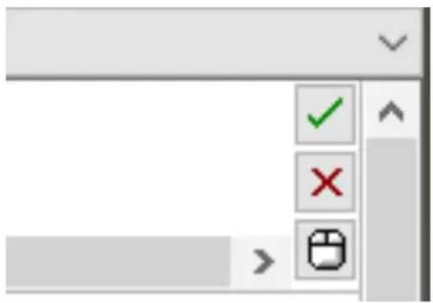
- When the correct Cell is lit, left-click in it and a large flashing cursor will appear in the left side of the Cell. You will also see a green tick, a red cross, and a mouse icon on the right side of the Cell.
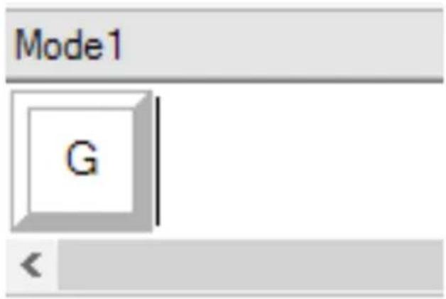
- The Cell is now waiting for the keyboard command. Using your keyboard, press the button on the keyboard you would like Button 'A' on the stick to activate. For this example we will use the 'G' key, which usually activates landing gear. When you press 'G' on the keyboard, a large white tile with the letter 'G' should appear in the Cell, as shown here. If this is the correct keyboard command, press the green tick icon on the right side. If not, press the red cross and redo the procedure to get the keyboard command into the Cell again.
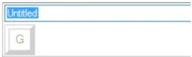
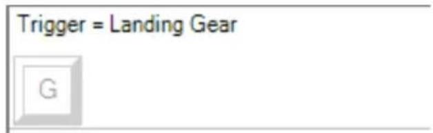
- After pressing the green tick icon, the command name box will appear, labeled as "Untitled" (left image, below). Simply choose a name for the command and type the name into this box. For this example, we chose "Landing gear." Press the enter key to complete the Cell. Button 'A' = Landing gear, which is your keyboard's 'G' key (right image, below).
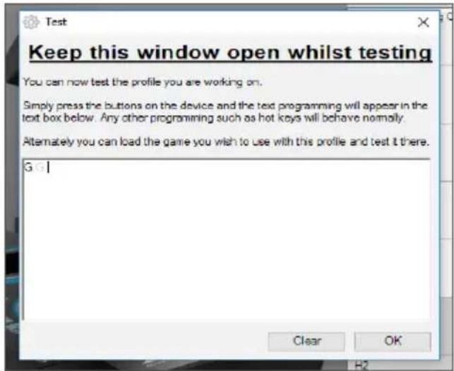
- Test your Profile by opening the "Testing" window. Above the 3D image there are seven icons. The one that is second from the right, which looks like a silver cog, is labeled "Test Profile."
Click on this icon and a new window will open. A cursor will already be flashing in the test area. Simply press Button 'A' on the X56. When this is pressed, letter 'G' will appear in the window, which proves your first programmed button is working.
Close this window by clicking on the "OK" icon in the bottom-right corner of the Testing window.
- You can add other keyboard commands if you wish and then test them. Just remember to save your work before you shut down the software.

- To make the programming you have just created work in your game, you must first save it as a Profile and then activate it. This can be done with one click. In the icon row just above the 3D image, you will see an icon that looks like a blue target. If you hover over this icon a tool tip labeled "Profile" will appear.
Click this icon and a standard Windows save box will appear. Give your Profile a name and save it. After saving, the Profile will become active and you can shut down the software and play your game. The X56 will now respond as you have programmed it.
- The software is capable of many other powerful programming features that we have not yet covered. For example, you can program axes, mouse movement and mouse buttons, hats, and special timed or complicated commands.
Icons in the Profile Editor

1. New Profile
Opens a blank Profile for you to edit/build.
2. Open Profile
Opens a previously created Profile for editing.
3. Save Profile
Clicking "Save" will save a new Profile or overwrite a current Profile.
Using the drop-down arrow next to "Save," you can "Save as," allowing you to save the current Profile to a different location or as a different name.
4. Views
You can change the view in the Profile Editor to be just programming Cells (i.e., no image). Clicking the "Views" button again will restore the default view and the image will reappear.
5. Profile
If you are working on a Profile to use immediately, so you can get flying straight away, click here.
6. Test Profile
Clicking this icon will bring up the test window. This is especially useful if you are attempting to program advanced timed or macro commands as it gives you a place to test your work before you fly.
7. Print
By pressing this icon, the Profile that you are currently building will be sent to the default printer on your system.
Settings
The settings page will allow you to alter the deadzone and response curves of all axes on both the Stick and the Throttle.
Response Curves
Depending on the type of aircraft that you fly, you may want your joystick to be more or less sensitive around the middle or end points of the axes. For example, if you're flying an F/18 on a refueling mission at 25,000 feet, you will be making very fine movements to get into the correct position. Having a shallower response curve around the center point of the joystick's X and Y axes will enable you to make very fine adjustment to your aircraft.
Deadbands
A deadband, sometimes known as a deadzone or neutral zone, is a part of the range in which an axis moves, undetected by the drivers and without effect on in-game progress. It may be around the center point of the axis range, or at either end of the axis range.
Axis Range Adjustment
The axis range adjustment, or axis saturation to assign its correct name, allows you to shrink the raw data range of an axis.
Physical Axis Adjustment
The physical axis adjustment, or physical saturation, allows you to shrink the full axis data range into a small physical stick movement.
S-Curves and J-Curves
There are two types of adjustable curves - S-Curves and J-Curves. J-Curves are linear axes, like throttles and rotaries. S-Curves are non-linear, like X and Y axes.
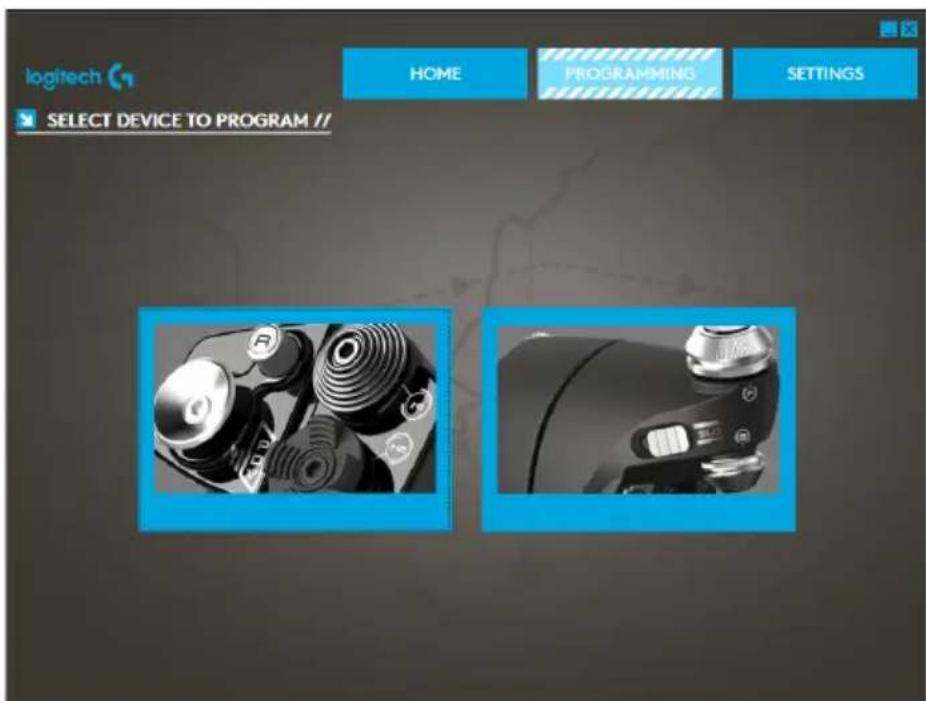
The first screen you'll see is the 'SELECT DEVICE TO MODIFY' screen.
You have two choices; choose to alter either the Stick or the Throttle axis.
Once you are in the 'STICK // AXIS MODIFICATION' screen, you'll see a raft of options. We'll go through them one by one.
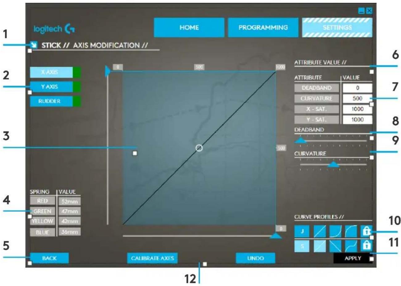
- Name of the Part being Modified
2.Modifiable Axes - Manual Axis Adjustment and Test Area
- Spring Values - for Reference when Changing Axis Data
- Back Button
- Physical Axis Adjustment Slider
- Manual Axis Attribute Boxes
- Deadzone Adjustment
- Axis Curvature Adjustment
- Pre-made Profiles
- Apply Button
- Undo Button
1. Name of the Part being Modified
This will either be the Stick or the Throttle unit for the X-56. If you wish to change the part that you're not currently on, use the back button (5) to go back to the selection screen.
2.Modifiable Axes
This shows a list of all modifiable axes. The Stick has three modifiable axes:
- X Axis
- Y Axis
Rudder Axis
The Throttle unit has six modifiable axes:
- Left Throttle
-Right Throttle - Rotary1
Rotary 2 - Rotary 3
- Rotary 4
3. Manual Axis Adjustment and Test Area
This area will show you how the current response curves / dead zones / saturation points are set up on the selected axis. You can also adjust the center deadzone, the range saturation, physical saturation, and the response curve on the selected axis. There is also a cross-hair which will show the physical position of the axis you are manipulating.
4. Spring Values
This is a reference section when you are adjusting the axes on the Stick. It will act as a guide for axis modification, and you may choose differing axis curves or deadzones depending on the Spring you have fitted to the Stick. If you are modifying the Throttle unit's axes you will not see this reference section.
5. Back Button
Takes you to the device selection screen.
6. Physical Axis Adjustment Slider
Allows the ends of the axes, the far left and far right on the X Axis or full up and full down on the Y Axis, to be moved inwards towards the center point. It is similar to setting up a deadzone at the far ends of your axis.
7. Manual Axis Attribute Boxes
This area allows you to input raw data to setup your deadband, curvature, range saturation, and physical saturation settings. This is very useful if you already have the data or a third-party source is supplying the data. For example, a forum post on how to setup the response curve for an F/A-18F.
8. Deadzone Adjustment
The deadzone slider will allow you to adjust the deadzone around the center point of the axis you currently have selected.
9. Axis Curvature Adjustment Slider
Shrinks the range of an axis. Instead of going from 0 to 65555, for example, we can shrink it to 300 to 62555.
10. Pre-made Profiles
We have included a set a predefined curves to select. This is to make it easier for those who do not wish to make their own curves. There are two different types of curves to choose from:
- J-Curves - these curves will give you a single point of manipulation and are ideal for throttles and rotaries.
- S-Curves - these curves will give you two points of manipulation and are ideal for setting up X and Y axes.
11. Apply Button
This button will save the curve that you are manipulating on the selected axis. Once saved, this axis will perform as saved, for all games, until the axis is adjusted and resaved or the reset button is used.
12. Undo Button
This button will turn the response curves on your currently selected axis back to their default state. This can be very useful when experimenting with curves and deadbands.
Altering Axis Attributes
Axis Status Notifications
You'll need to be aware of several notifications in the axis highlighter box when manipulating and applying axis data. On the left is a list of the current device's axes. The colors indicate the status of each axis.
X AXIS
Light Blue in the larger box indicates the currently selected axis. Green in the smaller box indicates that the data on the settings page and the data on the device are in sync for this axis.
X.AXIS
Yellow in the smaller box indicates that the data for this axis has been modified on the settings page but has not yet been synced to the device.
AX15
To sync data, click 'Apply' in the bottom right. The entire box will turn Yellow then start to fill up Green to indicate that the data on the settings page is being synced to the device. Once data is fully synced, the larger box will revert to Light Blue and the smaller box will stay Green.
X AXIS
X AXIS
When the Axis box turns Green, the data from the settings page saves to the physical device. The main Axis box will then turn Blue and the slash will turn to Green.
Setting a Deadzone
To set a deadzone on an axis, whether it's an S-Curve or a J-Curve, simply move the deadzone slider (part 8). You will see the axis start to split from the middle in the manual adjust area. The deadzone will become larger as the slider moves farther.
Setting a Response Curve
To set a response curve on an axis, whether it's an S-Curve or a J-Curve, simply move the curvature slider. On an S-Curve setting you will see the curve turn snake-like, which indicates curvature above and below the center point the axis.
On a J-Curve setting you will see the whole axis curve as the slider moves. You can also change the curvature of either curve by moving the points in the manual adjustment area (part 4). If you move the points in the area, 2 for an S-Curve and 1 for a J-Curve, then the curve will adjust to the new points.
Setting an Axis Range
To set an axis range, simply move the Axis Range Adjustment Slider (part 5). This will shrink the data for that axis from the full negative side and from the full positive side. Now when you use the axis that you have just altered, the axis data output will only output up to the points that you have set in the settings.
Setting a Physical Axis
To set the physical axis range on any axis, move the Physical Axis Adjustment Slider (part 6). Moving this slider will shrink the minimum and maximum range of the physical axis. After moving the sliders to set your axis, every time you move the physical axis you'll see that the minimum and maximum range has shrunk.
Saving a Setting
To save settings so they're usable, click the 'Apply' Button in the bottom right-hand corner of the screen (part 13). Once you've hit 'Apply,' the axis icon (part 1) will turn Yellow, and progressively turn Green. A Green end segment and Blue main axis indicates saved data. For more details on axis notification, please check the 'Axis Notifications' section.
TROUBLESHOOTING
Q1 My computer is not recognizing the Controller, what's wrong?
A 1. Have you downloaded and installed the drivers from support.logitech.com?
A 2. Check the cable connections. Unplug your controller and plug it back in, making certain that it is securely attached.
A 3. If you're using front or top facing USB ports, try plugging into the back of the PC.
A 4. If using a hub, make sure it's a powered hub.
Q2 Why doesn't the game I'm playing recognize my Controller?
A 1. Ensure that you have conducted the checks in Q1 [above].
A 2. Does the game you are playing offer support for game controllers? Please refer to your game's manual, which should contain information regarding the use of game controllers. If it does not, you can use the powerful programming software to emulate the mouse and keyboard on your X56 HOTAS.
Q3 One of the buttons or axes is not working on my controller.
A 1. Please test your product in the Game Controllers panel as mentioned in the early part of this manual.
A 2. If you are still experiencing problems with the controller, please contact the tech support team at http://support.logitech.com/Tickets/Submit
Q4 In flight simulation games, like FSX, why doesn't my aircraft correctly respond to axes?
A1 The X56 HOTAS stick and throttle units are independent units, therefore they both have an X Axis, a Y Axis, etc. It is a simple case of going into the controller settings for your simulation game and setting up the X56 HOTAS. For a more detailed overview on how to do this please visit our FAQ page: logitech.com/support/x56
Q5 How do I change the X56 HOTAS LED color and brightness?
A 1 Install the software to find a brightness slider under the SETTINGS tab.