Micro Converter HDMI to SDI wPSU - Audio/video converter Blackmagic Design - Free user manual and instructions
Find the device manual for free Micro Converter HDMI to SDI wPSU Blackmagic Design in PDF.
User questions about Micro Converter HDMI to SDI wPSU Blackmagic Design
0 question about this device. Answer the ones you know or ask your own.
Ask a new question about this device
Download the instructions for your Audio/video converter in PDF format for free! Find your manual Micro Converter HDMI to SDI wPSU - Blackmagic Design and take your electronic device back in hand. On this page are published all the documents necessary for the use of your device. Micro Converter HDMI to SDI wPSU by Blackmagic Design.
USER MANUAL Micro Converter HDMI to SDI wPSU Blackmagic Design
Installation and Operation Manual
Blackmagic Converters
June 2018
English, 日本語, Français, Deutsch, Espanol, 中文, 한국어, Рсккий and Italiano.
Languages
To go directly to your preferred language, simply click on the hyperlinks listed in the contents below.
English 3.
日本語 92
Français 182
Deutsch 272
Espanol 362
中文 452
542
Pycckn 632
Italiano 722

Welcome
Thank you for purchasing Blackmagic Converters for your production needs.
Blackmagic Mini Converters, Mini Converter Heavy Duty, Battery Converters and Micro Converters give you a solution for virtually any conversion you could need. Mini Converters convert analog to digital, digital to analog, SDI to audio, audio to SDI, up, down and cross conversion, SDI distribution, and can even provide a sync generator for locking all your video equipment to the same reference signal. Mini Converter Heavy Duty gives you the same conversions in a super tough design that's perfect for use on location and Battery Converters let you work on location with or without external power. Blackmagic Micro Converters are even smaller, designed for popular conversions such as SDI to HDMI and HDMI to SDI so you can plug any HDMI output into SDI video recorders and switchers, or plug SDI video equipment into HDMI monitors.
This instruction manual contains all the information you need to start using your Blackmagic Converters.
Please check the support page on our web site at www.blackmagicdesign.com for the latest version of this manual and for updates if your Blackmagic Converter has internal software. Keeping your internal software up to date will always ensure you get all the latest features. When downloading software, please register with your information so we can keep you updated when new software is released. We are constantly working on new features and improvements, so we would love to hear from you!

Grant Petty
CEO Blackmagic Design
Contents
Blackmagic Converters
Getting Started 4 Mini Converter HDMI to SDI 4K 33
Plugging in Power 4 Mini Converter HDMI to SDI 6G 36
Plugging in Video 5 Mini Converter SDI to Analog 39
Plugging in Audio 6 Mini Converter SDI to Analog 4K 44
Installing Administration Software 7 Mini Converter Analog to SDI 48
Installling Blackmagic Converters Setup 7 Mini Converter SDI to Audio 52
Updating the Internal Software 8 Mini Converter SDI to Audio 4K 55
Updating Mini Converter SDI Mini Converter Audio to SDI 58
Distribution 4K 9 Mini Converter Audio to SDI 4K 62
Changing Settings 10 Mini Converter Optical Fiber 66
Changing Settings using Switches 10 Mini Converter Optical Fiber 4K 67
Changing Settings using Mini Converter Optical Fiber 12G 68
Blackmagic Converters Setup 11
About Tab 12 Minr Converter Quad SDI to HDMI 4K 69
Blackmagic Converter Models 12
Teranex Mini Converters 12
Blackmagic Micro Converters 13 Mini Converter Super Generator 75
Micro Converter SDI to HDMI 13
Micro Converter HDMI to SDI 14 Micro Converter HDSOHD
Micro Converter BiDirectional SDI/HDMI 16 Converter Setup Utility 85
Blackmagic Mini Converters 18 Blackmagic Battery Converters 86
Mini Converter SDI to HDMI 18 Battery Converter SDI to HDMI 86
Mini Converter SDI to HDMI 4K 21 Battery Converter HDMI to SDI 87
Mini Converter SDI to HDMI 6G 25 Help 89
Mini Converter HDMI to SDI 30 Warranty 90
Getting Started
Getting started with your Blackmagic Converter is as simple as plugging in power, plugging your source video into your converter's video input, and plugging the video output into your destination equipment.
Plugging in Power
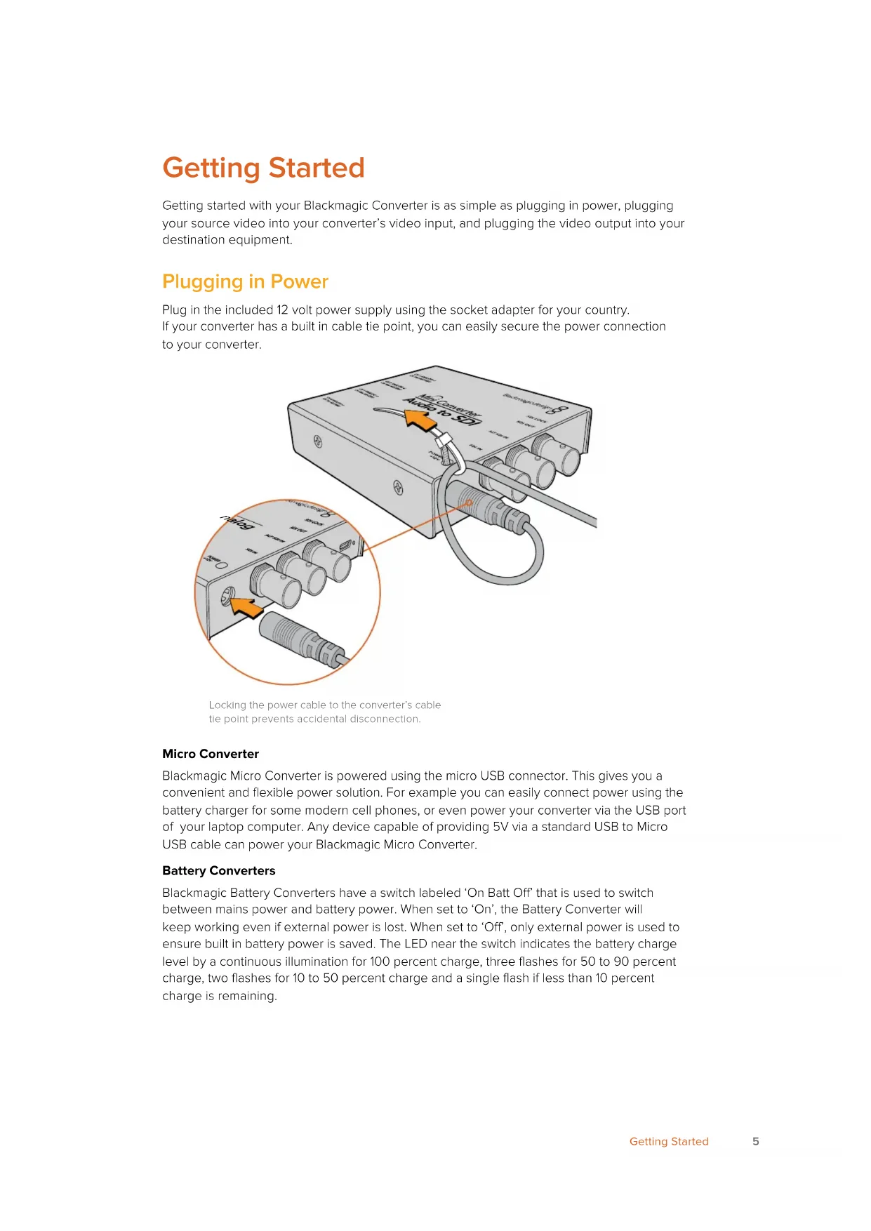
Plug in the included 12 volt power supply using the socket adapter for your country. If your converter has a built in cable tie point, you can easily secure the power connection to your converter.
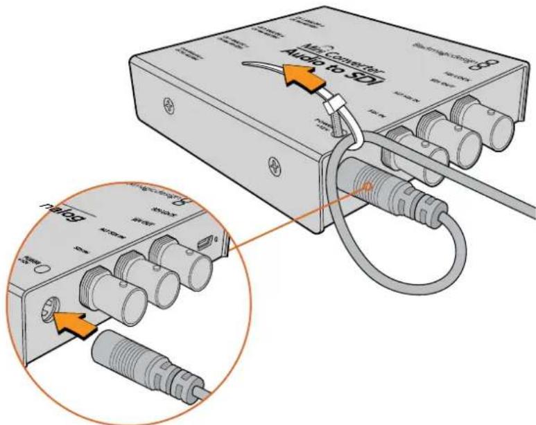
Locking the power cable to the converter's cable tie point prevents accidental disconnection.
Micro Converter
Blackmagic Micro Converter is powered using the micro USB connector. This gives you a convenient and flexible power solution. For example you can easily connect power using the battery charger for some modern cell phones, or even power your converter via the USB port of your laptop computer. Any device capable of providing 5V via a standard USB to Micro USB cable can power your Blackmagic Micro Converter.
Battery Converters
Blackmagic Battery Converters have a switch labeled 'On Batt Off' that is used to switch between mains power and battery power. When set to 'On', the Battery Converter will keep working even if external power is lost. When set to 'Off', only external power is used to ensure built in battery power is saved. The LED near the switch indicates the battery charge level by a continuous illumination for 100 percent charge, three flashes for 50 to 90 percent charge, two flashes for 10 to 50 percent charge and a single flash if less than 10 percent charge is remaining.
Plugging in Video
To connect your video inputs and outputs, simply plug your source video into your converter's video input and plug the video output into your destination equipment.
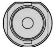
BNC HDMI Optical Fiber
Depending on your Blackmagic Converter model, the video connectors may be BNC, HDMI, or optical fiber LC.
Optical Fiber Connectors
Some Blackmagic Converter models include an SFP socket to accept a compatible SFP optical fiber module that supports up to 3G, 6G or 12G-SDI video. The module is an optical transmitter and receiver with sockets for optical fiber cables.
Examine the Optical Out/In socket to make sure it is free of dust.

Remove the protective cover from the SFP optical fiber module, and insert it in the SFP socket. A locking pin clicks into position to secure the module in the socket.
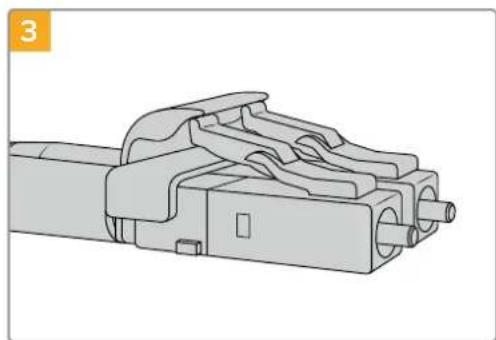
The optical fiber cables have latching tabs on top to make sure they don't fall out.
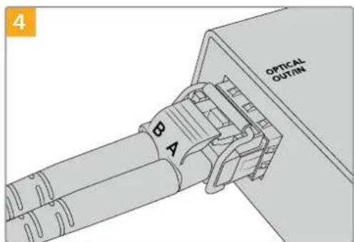
Plug in the optical fiber cables. Confirm the Out and In plugs are in the correct sockets, and that the locking tabs on the plugs hold the lever of the SFP optical fiber module upright.
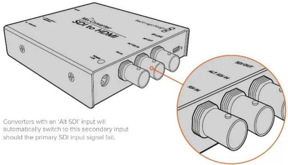
Fail Safe Alternate SDI inputs
Some Blackmagic Converter models include alternative SDI inputs for redundancy. These inputs are labeled 'Alt SDI In' and will immediately take over should the primary SDI input signal fail. In this rare scenario, the SDI LOCK LED will flash, indicating that the converter has switched to the ALT SDI input.
Plugging in Audio
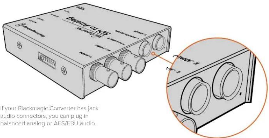
Jack Audio Connectors
Some Blackmagic Converters have built in 1/4" jacks, so you can easily plug in balanced external analog or digital AES/EBU audio. The 1/4" jacks are balanced TRS connectors. TRS stands for Tip, Ring, Sleeve which refers to the three contacts of the jack connector.
Below is an illustration showing the wiring pins inside the male 1/4" jack connector if you want to make your own audio cables.
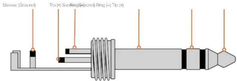
The audio jack illustration on the previous page shows the jack connector's positive, negative and ground wiring pins. If you need to reverse the polarity of your analog audio cable to suit your audio equipment, you can simply swap the positive and negative wiring on the tip and ring pins.
NOTE If you are connecting stereo analog audio, it's worth mentioning that if you reverse the polarity for one channel jack connector, make sure you do the same for the second or your stereo analog audio will be out of phase.
Installing Administration Software
Installing Blackmagic Converters Setup
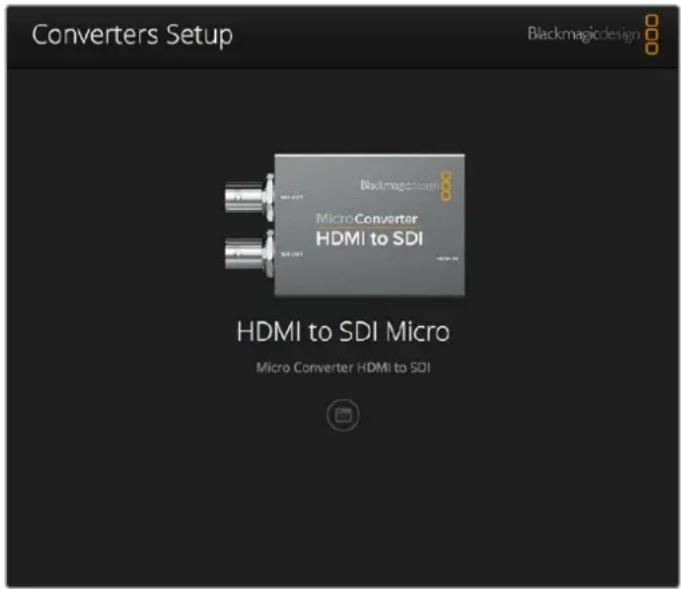
Blackmagic Converters Setup is used to change settings on your converter and to update your converter's internal software. The settings available will depend on the converter you are using. However, some Blackmagic Converters don't require any adjustable settings and don't have internal software, therefore these particular converters will not have a USB connector. If your converter is one of these, you can go straight to your converter model in this manual to learn more about it.
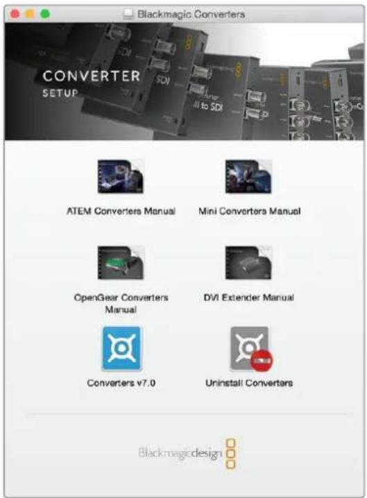
Blackmagic Converters Setup can be installed on Mac OS X and Windows computers.
Installation on Mac OS X
1 Download the Blackmagic Converters Setup software from www.blackmagicdesign.com
2 Unzip the downloaded file and open the resulting disk image to reveal its contents.
3 Double click the installer and follow the prompts to complete the installation.
4 When the installation has finished, click 'close'. Blackmagic Converters Setup is now installed.
Installation on Windows
1 Download Blackmagic Converters Setup from www.blackmagicdesign.com
2 Unzip the downloaded file. You should see a Blackmagic Converters Setup folder containing this PDF manual and the Blackmagic Converters Setup installer.
3 Double click the installer and follow the prompts to complete the installation.
4 Click 'finish' to complete the installation.
Blackmagic Converters Setup is now ready to use.
Updating the Internal Software
If your Blackmagic Converter has a USB connector, then you may have additional settings you can change, plus you can update your converter with the latest internal software. The latest software can be downloaded from the Blackmagic Design support center at www.blackmagicdesign.com/support.
When updating Blackmagic Micro Converters, power is already supplied via the USB port, so you don't have to worry about connecting power.
On Blackmagic Mini Converters, Battery Converters and Mini Converters Heavy Duty, you'll need to ensure your converter is powered before connecting to your computer via USB.
1 Power your converter.
2 Attach a USB cable from the computer to the converter and launch the Blackmagic Converter Setup.
Your Blackmagic Converter will be displayed on the setup utility's home page. If you have more than one converter connected via USB, click on the arrow icons on the left or right side of the home page to select your desired converter.
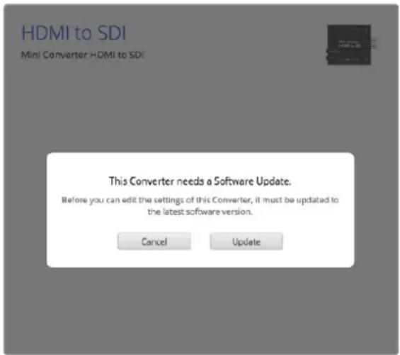
If Blackmagic Converters Setup detects an earlier version of your converter's internal software, it will prompt you to update.
If no converter is connected, the home page will display "no converters found". If you have a converter connected to your computer via USB, but you don't have power plugged in, the home page may display 'no power connected'. Simply plug power into your converter to access the settings.
If Blackmagic Converters Setup contains newer internal software than that currently installed in your Blackmagic Converter, it will prompt you to update. Simply follow the on screen instructions to complete the update.
Updating Mini Converter SDI Distribution 4K
Blackmagic Mini Converter SDI Distribution 4K has an internal USB connector. This mini converter has no user adjustable settings, so you will never need to connect setup software. Very occasionally, though, internal software updates will be released to improve compatibility with some devices. For example, Blackmagic Converters Software version 7.0.9 improves this mini converter's compatibility with level A 3G SDI signals.
If a particular update applies to the equipment you are using with Mini Converter SDI Distribution 4K, follow these steps to access your mini converter's USB connector:
NOTE Make sure you disconnect power before accessing your Mini Converter SDI Distribution 4K. We recommend this job is undertaken by a qualified engineer using an anti static strap.
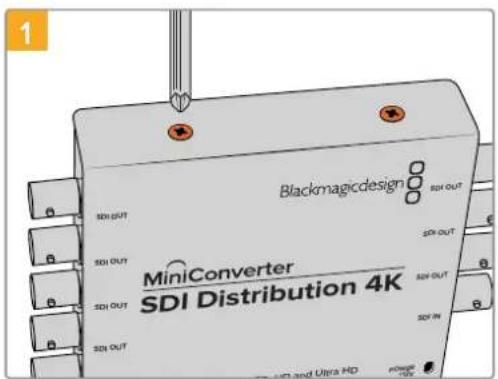
Using a philips head screwdriver, remove the four (M3) screws on the sides of Mini Converter SDI Distribution 4K.
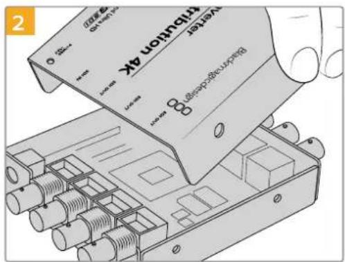
Slide off the external cover.
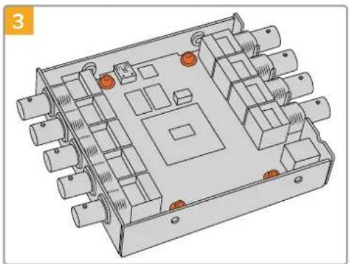
Using a T10 torx screwdriver, remove the four screws connecting the circuit board to Mini Converter SDI Distribution 4K's frame.
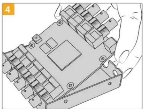
Gently pull the circuit board from the frame to access the USB connector.

Plug in your Mini Converter SDI Distribution 4K's power supply and connect it to a computer using a USB cable. Update the internal software as you would any other mini converter.
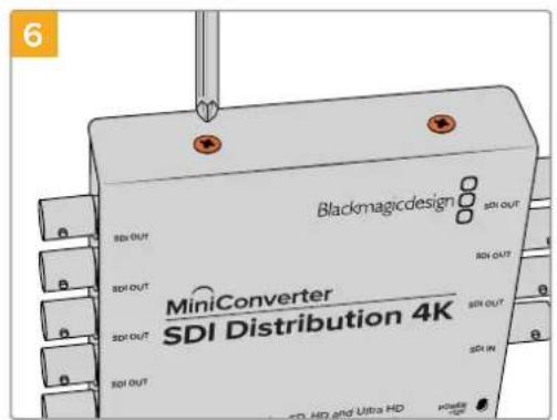
Repeat steps 1-4 in reverse to reassemble Mini Converter SDI Distribution 4K.
NOTE When handling your Mini Converter SDI Distribution 4K's circuit board, be careful to always hold it by the edges to prevent accidentally short circuiting internal components.
Changing Settings
If your Blackmagic Converter has adjustable settings, there are two ways you can change them. You can use the built in switches on the side of your converter, or you can change settings using the Blackmagic Converters Setup utility software. The utility is also used to change any settings that can't be set using the switches, for example analog video and audio levels.
Changing Settings using Switches
Many Blackmagic Converter models have built in switches.
To change a switch setting simply push the switch up or down using the tip of a pen. This turns the switches on or off. With 8 switches, this gives you many combinations so you can choose exactly the conversion settings you want.
You'll find a switch settings diagram printed on the base of your converter. Ensure your switch settings correspond to the legend by observing the switch numbers from 1 to 8, left to right.
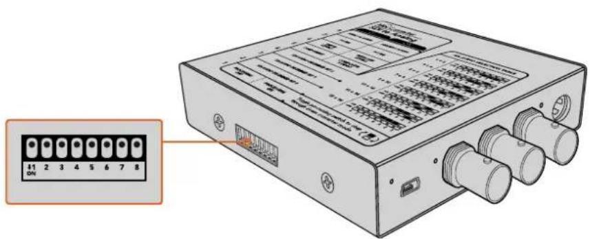
Change settings by adjusting the switches with a pen.
For a full description of the switches and their settings, refer to your converter model in this manual. Even though switch settings are printed on the base of your converter, new features in later updates can add new settings so it's worth checking the latest version of this manual for the most up to date information. You can download the latest version from the Blackmagic Design support center at www.blackmagicdesign.com/support.
Changing Settings using Blackmagic Converters Setup
Once Blackmagic Converters Setup is installed on your computer, connect the setup utility to your Blackmagic Converter via USB.
The Blackmagic Converters setup utility lets you update your converter's internal software and adjust settings using a Mac OS X or Windows computer.
The first thing you'll see when launching the software is the 'home' page. If you have more than one converter connected to your computer, select your desired converter by clicking the arrows on the left and right side of the Blackmagic Converters Setup home page.
To change settings, click on the 'settings' icon below the image of your Blackmagic Converter. Adjustments will be immediately saved to your converter. This means if power is lost, your settings will be reestablished as soon as power is restored.
Even though most settings are configured using the built in switches, some settings can only be set using the setup software, for example adjusting analog video or audio levels.
TIP Teranex Mini Converters are 12G-SDI converters that support even more video formats including up to 4K DCI 60p. If you are looking for information on how to use a Teranex Mini Converter, including how to change settings using the Blackmagic Teranex Setup utility, refer to the Teranex Mini Converters manual. You can download the most up to date manual from the Blackmagic Design support center at www.blackmagicdesign.com/support
About Tab
The 'about' tab in Blackmagic Converters Setup is common across all converter models. You can use the settings in this tab to name your Blackmagic Converter. Simply click in the 'name' text box and type your desired converter name. Click 'save' to confirm the change.

The 'about' tab in Blackmagic Converters Setup is used to name your Blackmagic Converter. You can also check the version of the setup software.
The 'Software Information' menu in the 'about' tab identifies which software version your Blackmagic Converter is running. If your converter's internal software is older than the current version that comes with Blackmagic Converters Setup, an update button will be present here that allows you to bring your converter's software up to date.
Blackmagic Converter Models
Blackmagic Converters provide conversion solutions for all types of conditions. For example, Mini Converters are tough and lightweight so you can mount them on video equipment or video trays, Battery Converters are super strong with a built in rechargeable battery so are portable and self powered and Blackmagic Micro Converters are tiny SDI to HDMI and HDMI to SDI converters that can be powered via USB so are perfect for attaching to monitors and laptop computers.
The following pages contain information about your Blackmagic Converter, plus switch settings and setup software settings.
Teranex Mini Converters
Blackmagic Teranex Mini Converters are 12G-SDI converters that support video formats up to 4K DCI 60p. These converters can be controlled using an optional Teranex Mini Smart Panel with built in LCD, buttons and a rotary knob, and can be powered via Ethernet. If you are looking for information about these converters, including controlling them via the Blackmagic Teranex Setup utility, refer to the Teranex Mini Converters manual which you can download from the Blackmagic Design support center at www.blackmagicdesign.com/support
Blackmagic Micro Converters
Micro Converter SDI to HDMI
With Micro Converter SDI to HDMI you can connect a huge range of HDMI displays and video projectors to SDI based equipment. Your Micro Converter SDI to HDMI automatically detects between SD/HD/3G-SDI and converts to HDMI with embedded audio. This tiny broadcast quality converter is protected by a strong aluminum chassis and powers over USB, meaning you can power your Blackmagic Micro Converter via your laptop or television's USB connector using a common micro USB cable. Micro USB cables are used to connect some cell phones to chargers and laptops, so if you have one of these, you can use the same cable. If the USB connector on your cable is a different type, the correct cable can be purchased from most electronic equipment stores.
Connectors
1 SDI In
Primary SDI input BNC connector.
2 SDI Loop
Loop through output of your SDI input BNC connector.
3 Micro USB / Power
Provides power from the included adapter or any device capable of providing 5V via a standard USB to Micro USB cable, such as a laptop or television. Also connects to Blackmagic Converters Setup software via your Mac OS X or Windows Computer.
4HDMI Out
HDMI type A video output.
Blackmagic Converters Setup Settings
The Blackmagic Converters Setup utility can be used to change settings and update your Micro Converter's software. You can access these settings by moving between the 'video' and 'about' tabs.
The 'about' tab is detailed in the 'changing settings' section in this manual.
The 'video' tab for Micro Converter SDI to HDMI contains the following settings.

The clip video output to legal levels' setting is checked by default. This setting ensures your HDMI output is a true representation of the SDI input.
Processing menu
The 'clip video output to legal levels' checkbox controls clipping of your SDI input to ensure that it stays within HDMI legal levels and should be kept on by default.
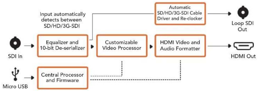
Micro Converter SDI to HDMI Block Diagram
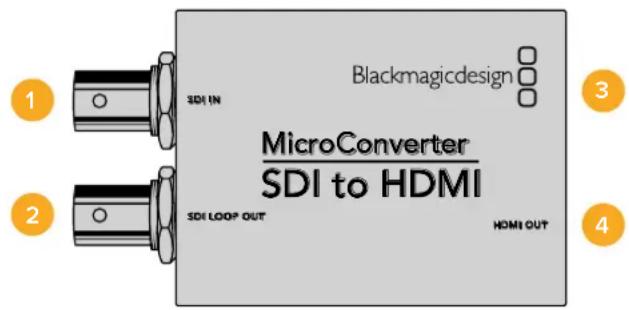
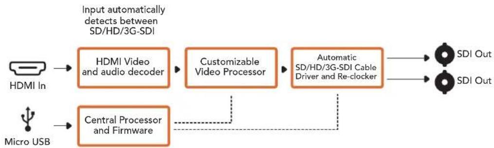
Micro Converter HDMI to SDI
You can use Micro Converter HDMI to SDI to convert HDMI outputs from devices such as HDV cameras and game consoles to SDI. This means you can send video signals from HDMI over SDI using the longest SDI cables. You can even add SDI outputs to computers with HDMI compatibility. This tiny broadcast quality converter is protected by a strong aluminum chassis and powers over USB, meaning you can power your Blackmagic Micro Converter via your laptop or television's USB connector using a common micro USB cable. Micro USB cables are used to connect some cell phones to chargers and laptops, so if you have one of these, you can use the same cable. If the USB connector on your cable is a different type, the correct cable can be purchased from most electronic equipment stores.
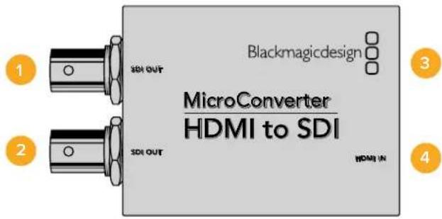
Connectors
1 SDI OUT
SDI video output BNC connector.
2 SDI OUT
Second SDI output.
3 Micro USB / Power
Provides power from the included adapter or any device capable of providing 5V via a standard USB to Micro USB cable, such as a laptop or television. Also connects to Blackmagic Converters Setup software via your Mac OS X or Windows Computer to update the Micro Converter's internal software.
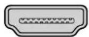
4HDMI In
HDMI type A video input.
Blackmagic Converters Setup Settings
The Blackmagic Converters Setup utility can be used to change settings and update your Micro Converter's software. You can access these settings by moving between the 'video,' and 'about' tabs.
The 'about' tab is detailed in the 'changing settings' section in this manual.
The 'video' tab for Micro Converter HDMI to SDI contains the following settings.

Use the 'video' tab in Blackmagic Converters Setup to toggle SDI levels.
Processing menu
The '3G Output' menu lets you select between Level A or Level B 3G-SDI. This setting lets you change the 3G-SDI output standard to maintain compatibility with equipment that can only receive level A or level B 3G-SDI video. Level B is the default setting.
Micro Converter HDMI to SDI Block Diagram
Micro Converter BiDirectional SDI/HDMI
Micro Converter BiDirectional SDI/HDMI converts SD and HD video from HDMI to SDI, and SDI to HDMI with embedded audio simultaneously. For example, you can convert the HDMI output from an HDV camera to SDI for longer cable lengths, while also converting an SDI return feed to HDMI so you can connect to an HDMI TV.
If you have only one input connected, the SDI and HDMI outputs both become loop outputs so you can feed the input signal to other HDMI and SDI equipment.
Your Micro Converter BiDirectional SDI/HDMI automatically detects SD/HD/3G-SDI input format and sets the output format to match.
This tiny broadcast quality converter is protected by a strong aluminum chassis. It is powered over USB, meaning you can power your Blackmagic Micro Converter BiDirectional SDI/HDMI from your laptop or television's USB connector using a common micro USB cable. Micro USB cables are used to connect some cell phones to chargers and laptops, so if you have one of these, you can use the same cable. If the USB connector on your cable is a different type, the correct cable can be purchased from most electronic equipment stores.
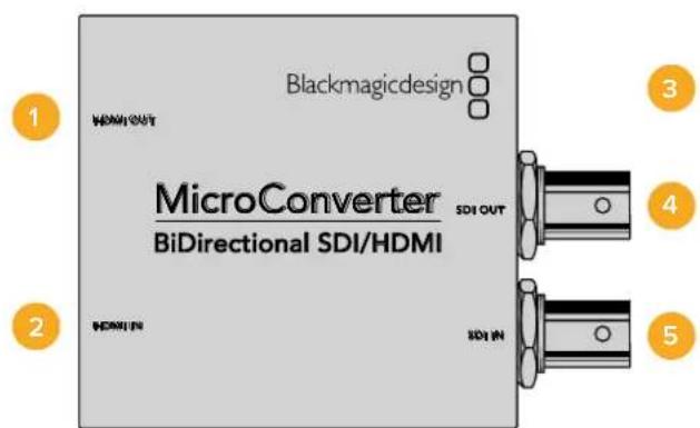
Connectors
1 HDMI Out
HDMI type A video output.
2HDMI In
HDMI type A video input.
3 Micro USB / Power
Provides 5V power from any device capable of providing 5V via a standard USB to Micro USB cable, such as a laptop or television. Also connects to Blackmagic Converters Setup software via your Mac OS X or Windows Computer.
4 SDI Out
SDI video output BNC connector.
5 SDIn
SDI video input BNC connector.
Blackmagic Converters Setup Settings
The Blackmagic Converters Setup utility can be used to change settings and update your Micro Converter's software. You can access these settings by moving between the 'video,' and 'about' tabs.
The 'About' tab is described in the 'Changing Settings' section in this manual.
The 'Video' tab for Micro Converter BiDirectional SDI/HDMI contains the following settings.
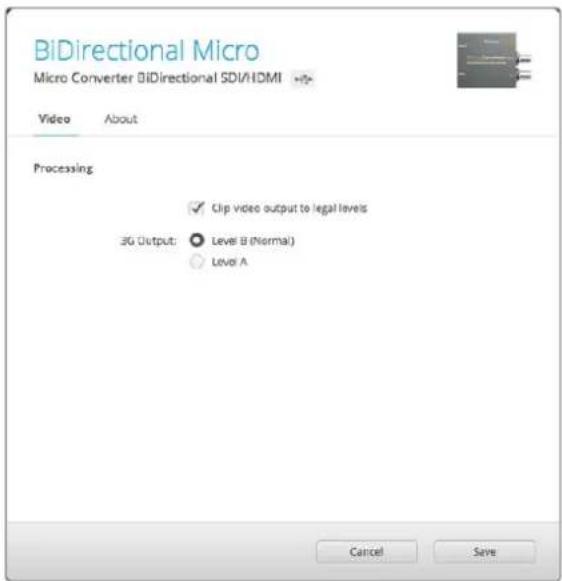
The 'Clip video output to legal levels' setting is checked by default. This setting makes sure your HDMI output is a true representation of the SDI input.
Processing menu
The 'Clip video output to legal levels' checkbox controls clipping of your SDI input to ensure that it stays within HDMI legal levels and should be kept on by default.
The '3G Output' setting lets you select between Level A or Level B 3G-SDI. This changes the 3G-SDI output standard to maintain compatibility with equipment that can receive only level A or level B 3G-SDI video. The default setting is Level B.
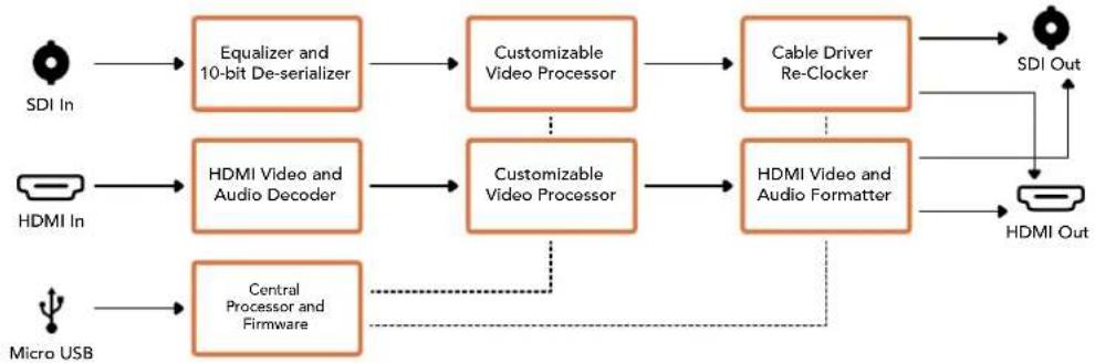
Micro Converter BiDirectional SDI/HDMI Block Diagram
Blackmagic Mini Converters
Mini Converter SDI to HDMI
Mini Converter SDI to HDMI can connect a huge range of HDMI displays and video projectors to SDI based equipment. Your Mini Converter SDI to HDMI automatically detects between SD/HD/3G-SDI and converts to HDMI with embedded audio, plus balanced AES/EBU or analog audio out.
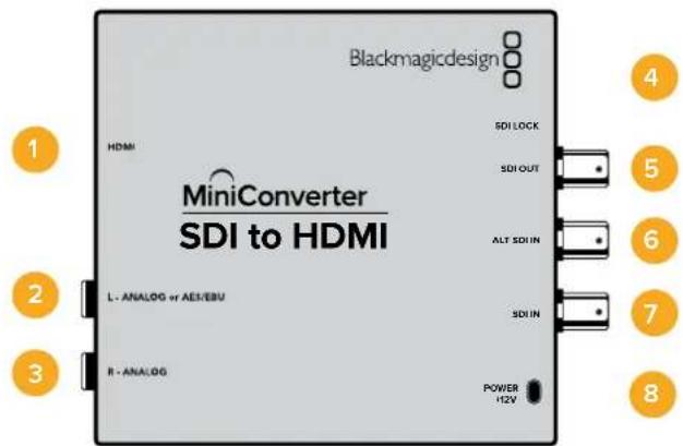
Connectors
1 HDMI
HDMI type A video output.
2 L-ANALOG or AES/EBU
Balanced left channel analog audio, or AES/EBU digital audio output on a 1/4" jack connector.
3 R-ANALOG
Balanced right channel analog audio output 1/4" jack connector.
4 MINI-B USB PORT
Connects to the Converters Setup software via your Mac OS X or Windows computer. The Mini Converter's internal software is also updated using the USB port.
5 SDI OUT
SDI video output on a BNC connector.
6 ALT SDI IN
Redundant SDI input is provided as an optional back up.
7 SDIN
Primary SDI input.
8 POWER +12V
12 volt power supply input.
Switches
Switch 8 - Analog Audio, AES/EBU Audio
Set switch 8 to OFF to select balanced analog audio, or to ON for digital AES/EBU audio output.
Switch 4 - SDI Audio De-Embed Bit 2
Switches 4, 3 and 2 are grouped together to provide 8 ON/OFF combinations. Having eight different combinations allows eight independent pairs of audio channels to be de-embedded from your SDI input and output to HDMI, analog or AES/EBU audio.
Switch 3 - SDI Audio De-Embed Bit 1
See switch 4 description.
Switch 2 - SDI Audio De-Embed Bit 0
See switch 4 description.
Switch 1 - Processing Off - Processing On
This switch is not used.
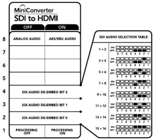
The switch legend on the base of your converter gives you all the information you need to change conversion settings.
Mini Switch Settings Example
Experiment with the switches by setting your Blackmagic Mini Converter to de-embed SDI audio channels 1 and 2 and output to analog by setting switches 8, 4, 3 and 2 to the OFF position.
SDI Audio Selection Table
| Audio Channels | Switch 4 | Switch 3 Switch 2 Switch Diagram | |
| 1 and 2 | OFF | OFF OFF | |
| 3 and 4 OFF ON | ON OFF 8 7 6 5 4 3 2 1 | ||
| 5 and 6 OFF ON | ON OFF 8 7 6 5 4 3 2 1 | ||
| 7 and 8 OFF ON | ON OFF 8 7 6 5 4 3 2 1 | ||
| 9 and 10 ON OFF | ON OFF 8 7 6 5 4 3 2 1 | ||
| 11 and 12 ON OFF | ON OFF 8 7 6 5 4 3 2 1 | ||
| 13 and 14 ON ON | ON OFF 8 7 6 5 4 3 2 1 | ||
| 15 and 16 ON ON | ON OFF 8 7 6 5 4 3 2 1 | ||
Blackmagic Converters Setup Settings
The Converters Setup utility can be used to change settings and update your Mini Converter's software. You can access these settings by moving between the 'video,' 'audio,' and 'about' tabs.
The 'about' tab is detailed in the 'changing settings' section in this manual.
The 'video' tab for Mini Converter SDI to HDMI contains the following settings.
Processing menu
The 'clip video output to legal levels' checkbox controls clipping of your SDI input to ensure that it stays within HDMI legal levels and should be kept on by default.
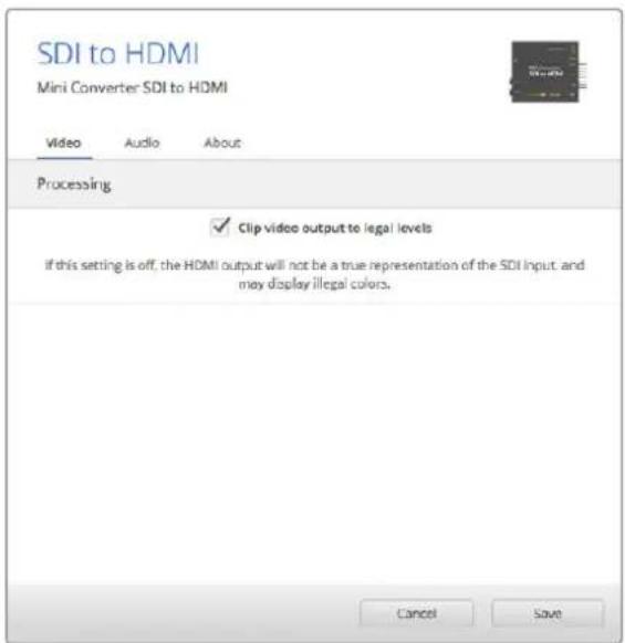
The 'clip video to legal levels' setting is checked by default. This ensures that your HDMI video output stays within legal levels.
The 'audio' tab for Mini Converter SDI to HDMI contains the following settings.
Output Levels menu
This menu allows you to adjust the gain on the audio output. You can adjust audio levels independently per channel, or together by clicking the 'link' icon next to their sliders. To reset all audio levels back to 0 dB click the 'reset' button at the top of the 'output levels' menu.

Use the 'audio' tab in Converters Setup to adjust audio levels.
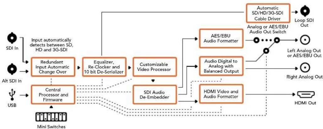
Mini Converter SDI to HDMI Block Diagram
Mini Converter SDI to HDMI 4K
With Mini Converter SDI to HDMI 4K and the SDI to HDMI 4K Heavy Duty model, you can connect a huge range of HDMI displays and video projectors to SDI based equipment. Your Mini Converter SDI to HDMI 4K automatically detects between SD/HD/3G/6G-SDI and converts to HDMI with embedded audio, plus balanced AES/EBU or analog audio out. The HDMI instant lock feature lets you lock the HDMI output so that changing sources using the same format is clean and glitch free. If your converter detects an HD monitor or TV connected to the HDMI output and has Ultra HD connected to the SDI input, the Ultra HD source will be automatically down converted so you can view the Ultra HD source on an HD monitor.
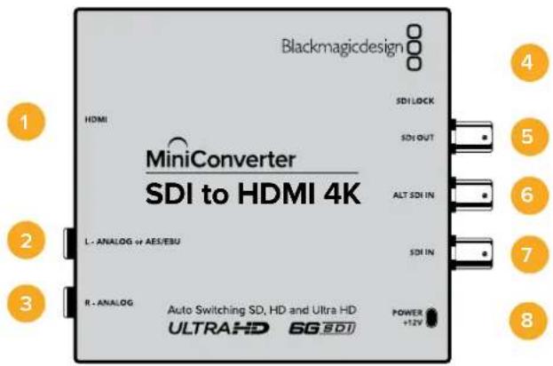
Connectors
1 HDMI
HDMI type A video output.
2 L-ANALOG or AES/EBU
Balanced left channel analog audio, or AES/EBU digital audio output 1/4" jack connector.
3 R-ANALOG
Balanced right channel analog audio output 1/4" jack connector.
4 MINI-B USB PORT
Connects to the Converters Setup software via your Mac OS X or Windows computer. The Mini Converter's internal software is also updated using the USB port.
5 SDI OUT
SDI video output BNC connector.
6 ALT SDI IN
Redundant SDI input is provided as an optional back up.
7 SDIN
Primary SDI input.
8 POWER +12V
12 volt power supply input.
Switches
TIP On the Mini Converter Heavy Duty model, the switches are protected by a rubber dust cover. Simply lift the edge of the cover to access the switches.
Mini Converter SDI to HDMI 4K's switches provide the following settings:
Switch 8 - Analog Audio, AES/EBU Audio
Set switch 8 to OFF to select balanced analog audio, or to ON for digital AES/EBU audio output.
Switch 4 - SDI Audio De-Embed Bit 2
Switches 4, 3 and 2 are grouped together to provide 8 ON/OFF combinations. Having eight different combinations allows eight independent pairs of audio channels to be de-embedded from your SDI input and output to HDMI, analog or AES/EBU audio.
Switch 3 - SDI Audio De-Embed Bit 1
See switch 4 description.
Switch 2 - SDI Audio De-Embed Bit 0
See switch 4 description.
Switch 1 - Processing Off - Processing On
This switch is not used.
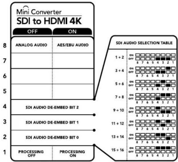
The switch legend on the base of your converter gives you all the information you need to change conversion settings.
Mini Switch Settings Example
Experiment with the switches by setting your Blackmagic Mini Converter to de-embed SDI audio channels 1 and 2 and output to analog by setting switches 8, 4, 3 and 2 to the OFF position.
SDI Audio Selection Table
| Audio Channels Switch 4 Switch 3 Switch 2 Switch Diagram | |||
| 1 and 2 OFF OFF OFF | ON OFF 8 7 6 5 4 3 2 1 | ||
| 3 and 4 OFF OFF ON | ON OFF 8 7 6 5 4 3 2 1 | ||
| 5 and 6 OFF ON OFF | ON OFF 8 7 6 5 4 3 2 1 | ||
| 7 and 8 OFF ON ON | ON OFF 8 7 6 5 4 3 2 1 | ||
| 9 and 10 ON OFF OFF | ON OFF 8 7 6 5 4 3 2 1 | ||
| 11 and 12 ON OFF ON | ON OFF 8 7 6 5 4 3 2 1 | ||
| 13 and 14 ON ON OFF | ON OFF 8 7 6 5 4 3 2 1 | ||
| 15 and 16 ON ON ON | ON OFF 8 7 6 5 4 3 2 1 | ||
Blackmagic Converters Setup Settings
The Converters Setup utility can be used to change settings and update your Mini Converter's software. You can access these settings by moving between the 'video,' 'audio,' and 'about' tabs.
The 'about' tab is detailed in the 'changing settings' section in this manual.
The 'video' tab for Mini Converter SDI to HDMI 4K contains the following settings.

The 'clip video to legal levels' setting is checked by default. This ensures that your HDMI video output stays within legal levels
Processing menu
HDMI Instant Lock
Select this checkbox to enable the HDMI instant lock feature. When HDMI instant lock is enabled, the HDMI output signal is kept active even when changing sources. This means your converter does not have to wait for the HDMI television or monitor to lock before displaying the video output as the HDMI signal is already locked. It's important to note that this feature only works when changing sources using the same video standard.
The HDMI instant lock feature can introduce a small delay in video and audio, so if you need zero delay in your converted output you can bypass the HDMI instant lock feature by deselecting the checkbox.
- Clip Video Output to Legal Levels
This checkbox controls clipping of your SDI input to ensure that it stays within HDMI legal levels and should be kept on by default.
Output Levels menu
This menu allows you to adjust the gain on the audio output. You can adjust audio levels independently per channel, or together by clicking the 'link' icon next to their sliders. To reset all audio levels back to 0 dB click the 'reset' button at the top of the 'output levels' menu.
The 'audio' tab for Mini Converter SDI to HDMI 4K contains the following settings.

Use the 'audio' tab in Converters Setup to adjust audio levels.
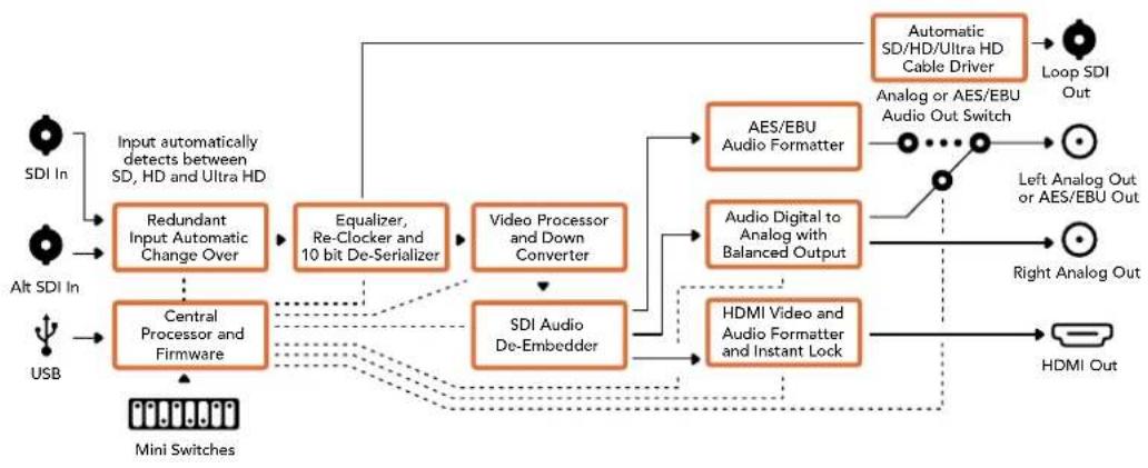
Mini Converter SDI to HDMI 4K Block Diagram
Mini Converter SDI to HDMI 6G
With Mini Converter SDI to HDMI 6G, you can connect a huge range of HDMI displays and video projectors to SDI based equipment. Your Mini Converter SDI to HDMI 6G automatically detects between SD SDI, HD-SDI, 3G-SDI and 6G-SDI input sources and converts to HDMI with embedded audio, plus balanced AES/EBU or analog audio out.
The HDMI instant lock feature lets you lock the HDMI output so that changing sources using the same format is clean and glitch free. If your converter detects an HD monitor or TV connected to the HDMI output and has Ultra HD connected to the SDI input, the Ultra HD source will be automatically down converted so you can view the Ultra HD source on an HD monitor.
You can also load 3D LUTs for adding looks, grades, and color profiles to your converted output. The 3D LUT is a full 33 point hardware lookup table for greater accuracy with color manipulation and can even be used to accurately color calibrate consumer televisions so they can be used for critical color correction work. The 3D LUT also allows color space conversions so different color spaces can be used with various displays. Your Mini Converter SDI to HDMI 6G comes with two default LUTs, including color to monochrome and Blackmagic camera default color space to REC 709.
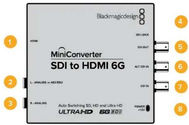
Connectors
1HDMI
HDMI type A video output.
2 L-ANALOG or AES/EBU
Balanced left channel analog audio, or AES/EBU digital audio output 1/4" jack connector.
3 R-ANALOG
Balanced right channel analog audio output 1/4" jack connector.
4 MINI-B USB PORT
Connects to the Converters Setup software via your Mac OS X or Windows computer. The Mini Converter's internal software is also updated using the USB port.
5 SDIOUT
SDI video output BNC connector
6 ALT SDI IN
Redundant SDI input is provided as an optional back up.
7 SDIN
Primary SDI input.
8 POWER +12V
12 volt power supply input.
Switches
Mini Converter SDI to HDMI 6G's switches provide the following settings:
Switch 8 - Analog Audio, AES/EBU Audio
Set switch 8 to OFF to select balanced analog audio, or to ON for digital AES/EBU audio output.
Switch 7 - LUT Off, LUT On
Set Switch 7 to OFF to disable the LUT, or to ON to enable the LUT.
Switch 6 - LUT 1, LUT2
Set Switch 6 to OFF to select LUT 1, or to ON to select LUT 2.
Switch 5 - LUT On Loop Off, LUT On Loop On
Set Switch 5 to OFF to select LUT On Loop Off, or to ON to select LUT On Loop On.
Switch 4 - SDI Audio De-Embed Bit 2
Switches 4, 3 and 2 are grouped together to provide 8 ON/OFF combinations. Having eight different combinations allows eight independent pairs of audio channels to be de-embedded from your SDI input and output to HDMI, analog or AES/EBU audio.
Switch 3 - SDI Audio De-Embed Bit 1
See switch 4 description.
Switch 2 - SDI Audio De-Embed Bit 0
See switch 4 description.
Switch 1 - HDMI Instant Lock Off, HDMI Instant Lock On
Set switch 1 to OFF to select HDMI Instant Lock Off, or to ON to select HDMI Instant Lock On.
When HDMI instant lock is enabled, the HDMI output signal is kept active even when changing sources. This means your converter does not have to wait for the HDMI television or monitor to lock before displaying the video output as the HDMI signal is already locked. It's important to note that this feature only works when changing sources using the same video standard.
The HDMI instant lock feature can introduce a small delay in video and audio, so if you need zero delay in your converted output you can bypass the HDMI instant lock feature by turning HDMI Instant Lock OFF.
The switch legend on the base of your converter gives you all the information you need to change conversion settings
Mini Switch Settings Example
Experiment with the switches by setting your Blackmagic Mini Converter to de-embed SDI audio channels 1 and 2 and output to analog by setting switches 8, 4, 3 and 2 to the OFF position.
SDI Audio Selection Table
| Audio Channels Switch 4 Switch 3 Switch 2 Switch Diagram | |||
| 1 and 2 OFF OFF OFF | ON OFF 8 7 6 5 4 3 2 1 | ||
| 3 and 4 OFF OFF ON | ON OFF 8 7 6 5 4 3 2 1 | ||
| 5 and 6 OFF ON OFF | ON OFF 8 7 6 5 4 3 2 1 | ||
| 7 and 8 OFF ON ON | ON OFF 8 7 6 5 4 3 2 1 | ||
| 9 and 10 ON OFF OFF | ON OFF 8 7 6 5 4 3 2 1 | ||
| 11 and 12 ON OFF ON | ON OFF 8 7 6 5 4 3 2 1 | ||
| 13 and 14 ON ON OFF | ON OFF 8 7 6 5 4 3 2 1 | ||
| 15 and 16 ON ON ON | ON OFF 8 7 6 5 4 3 2 1 | ||
Blackmagic Converters Setup Settings
The Converters Setup utility can be used to change settings and update your Mini Converter's software. You can access these settings by moving between the 'video,' 'audio,' and 'about' tabs. The 'about' tab is detailed in the 'changing settings' section in this manual.
The 'video' tab for Mini Converter SDI to HDMI 6G contains the following settings.

The clip video output to legal levels' setting is checked by default. This ensures that your HDMI video output stays within legal levels.
Processing menu
33 Point 3D LUT
Your Mini Converter SDI to HDMI 6G supports .cube LUT files that can be created using DaVinci Resolve software, or other color correction software that can export .cube files.
You can load 2 separate LUTs by clicking on the 'load' button for each LUT slot, selecting the desired .cube file from your computer, and clicking 'OK'. Click 'save' to confirm your settings. The LUT filename will appear next to each 'load' button so you know which LUT is being used for LUT 1 or LUT 2.
What is a 3D LUT?
A 3D LUT, or '3D Lookup Table', is a file containing table of values that are used to modify the video colorspace to a new set of color values in a 3D cube space.
The color cube contains all the variations between the mix of each primary color, defined within three x, y, z spatial dimensions. This means the RGB channels in the SDI input video can be remapped to any other RGB output color in the HDMI video output. This is very powerful as it means any color can be mapped to any other color so you can perform very precise color adjustments for calibrating displays, or loading log gamma curves for display when working with different types of raw camera files on set where you want to see linear gamma.
To show how powerful 3D LUTs can be, one of the default LUTs loaded can convert your input video to black and white. This shows that all the input RGB colors are remapped via the 3D LUT to black and white RGB output values via the HDMI output. You can create your own 3D LUTs and upload them via the admin software and DaVinci Resolve even allows you to convert a color grade setting to a 3D LUT that you can then upload to your Mini Converter SDI to HDMI 6G. You can output the 3D LUT on the SDI video loop output so you could even use your Mini Converter as a dedicated 3D LUT color processor even if you don't use the HDMI output!
For more information on how to create a 3D LUT .cube file, refer to the DaVinci Resolve manual which you can download from the Blackmagic Design website at www.blackmagicdesign.com/support.
- Clip Video Output to Legal Levels
This checkbox controls clipping of your SDI input to ensure that it stays within HDMI legal levels and should be kept on by default.
Output Levels menu
This menu allows you to adjust the gain on the audio output. You can adjust audio levels independently per channel, or together by clicking the 'link' icon next to their sliders. To reset all audio levels back to 0 dB click the 'reset' button at the top of the 'output levels' menu. The 'audio' tab for Mini Converter SDI to HDMI 6G contains the following settings.

Use the 'audio' tab in Converters Setup to adjust audio levels
Mini Converter SDI to HDMI 6G Block Diagram
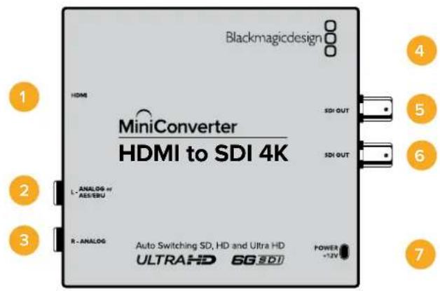
Mini Converter HDMI to SDI
Your Mini Converter HDMI to SDI can convert HDMI outputs from devices such as HDV cameras and game consoles to SDI with the choice to embed audio from HDMI, AES/EBU or balanced analog audio inputs. This means you can send video signals from HDMI over SDI using the longest SDI cables. You can even add SDI outputs to computers with HDMI compatibility. This converter also includes HD to SD down conversion.
Connectors
1 HDMI
HDMI type A video input.
2 L-ANALOG or AES/EBU
Balanced left channel analog audio or AES/EBU digital audio input on a 1/4" jack connector.
3 R-ANALOG
Balanced right channel analog audio input 1/4" jack connector.
4 MINI-B USB PORT
Connects to the Converters Setup software via your Mac OS X or Windows computer. The Mini Converter's internal software is also updated using the USB port.
5 SDIOUT
SDI video output on a BNC connector.
6 SDI OUT
Second SDI output.
7 POWER +12V
12 volt power supply input.
Switches
Mini Converter HDMI to SDI's switches provide the following settings:
Switch 8 - Analog Audio, AES/EBU Audio
Set switch 8 to OFF to select balanced analog audio, or to ON for digital AES/EBU audio input. To use these inputs Switch 7 must also be set to ON.
Switch 7 - HDMI Audio - Input Audio
Set switch 7 to OFF to select embedded HDMI audio, or to ON for analog or AES/EBU audio.
Switch 1 - Processing Off - Processing On
Down convert HD to SD with 3 types of aspect ratios by cycling through switch 1. For example, each time you cycle between OFF and On you apply anamorphic, center cut or letterbox aspect ratios. Leaving switch 1 set to OFF bypasses the down converter and outputs in HD.
When connected to the Blackmagic Converters Setup via USB, your down conversion settings are controlled by the software. If you want the converter to remember your software settings, disconnect from the computer, power cycle your converter and set your down conversion using mini switch 1.
The switch legend on the base of your converter gives you all the information you need to change conversion settings.
Blackmagic Converters Setup Settings
The Converters Setup utility can be used to change settings and update your Mini Converter's software. You can access these settings by moving between the 'video,' 'audio,' and 'about' tabs.
The 'about' tab is detailed in the 'changing settings' section in this manual.
The 'video' tab for Mini Converter HDMI to SDI contains the following settings.
Processing menu
This menu lets you select the aspect ratio of content that is down converted from HD to SD. The options are 'letterbox,' 'anamorphic,' 'center cut', or 'off.'
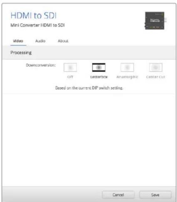
Use the 'video' tab in Converters Setupo adjust processing settings.
The 'audio' tab for Mini Converter HDMI to SDI contains the following settings.
Input Levels menu
This menu allows you to adjust the gain on the audio input. You can adjust audio levels independently per channel, or together by clicking the 'link' icon next to their sliders. To reset all audio levels back to 0 dB click the 'reset' button at the top of the 'input levels' menu.
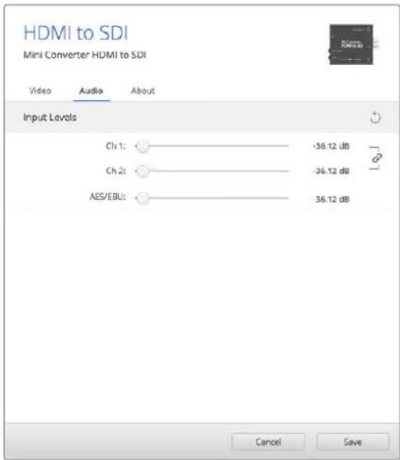
Use the 'audio' tab in Converters Setup to adjust audio levels.
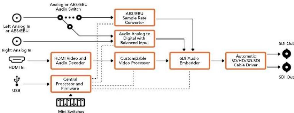
Mini Converter HDMI to SDI Block Diagram
Mini Converter HDMI to SDI 4K
Your Mini Converter HDMI to SDI 4K and the HDMI to SDI 4K Heavy Duty model can convert HDMI outputs from devices such as HDV cameras and game consoles to SDI with the choice to embed audio from HDMI, AES/EBU or balanced analog audio inputs. This means you can send video signals from HDMI over SDI using the longest SDI cables. You can even add SDI outputs to computers with HDMI compatibility.
Connectors
1 HDMI
HDMI type A video input.
2 L - ANALOG or AES/EBU
Balanced left channel analog audio or AES/EBU digital audio input 1/4" jack connector.
3 R-ANALOG
Balanced right channel analog audio input 1/4" jack connector.
4 MINI-B USB PORT
Connects to the Converters Setup software via your Mac OS X or Windows computer. The Mini Converter's internal software is also updated using the USB port.
5 SDIOUT
SDI video output BNC connector.
6 SDI OUT
Second SDI output.
7 POWER +12V
12 volt power supply input.
Switches
TIP On the Mini Converter Heavy Duty model, the switches are protected by a rubber dust cover. Simply lift the edge of the cover to access the switches.
Mini Converter HDMI to SDI 4K's switches provide the following settings:
Switch 8 - Analog Audio, AES/EBU Audio
Set switch 8 to OFF to select balanced analog audio, or to ON for digital AES/EBU audio input. To use these inputs Switch 7 must also be set to ON.
Switch 7 - HDMI Audio - Input Audio
Set switch 7 to OFF to select embedded HDMI audio, or to ON for analog or AES/EBU audio.
Switches 2, 1 - Select Format Bit 1,0
When connecting an HDMI source that can output Ultra HD and HD, you can set your converter to force the source output to one or the other. This can be helpful when you want to record or display your computer's desktop on SDI equipment in HD so it is larger and easy to view.
While it may appear like it's an up or down conversion setting, what your converter is actually doing is telling your source equipment to output Ultra HD or HD video so that your converter can then output the source video's native HD or Ultra HD resolution without up or down conversion.
To force your source video to HD, Ultra HD, or to let your converter automatically negotiate the optimum resolution with your source equipment, simply use combinations of switches 1 and 2.
The combination settings are shown below.
AUTO - switch 1 to OFF, switch 2 to OFF.
Your converter will negotiate an optimum HD or Ultra HD resolution with your source equipment based on its output capabilities.
FORCE TO HD - switch 1 to OFF, switch 2 to ON.
If your HDMI source equipment is capable of outputting HD and Ultra HD, your converter will instruct the source equipment to output HD video.
FORCE TO ULTRA HD - Switch 1 to ON, Switch 2 to OFF.
If your HDMI source equipment is capable of outputting HD and Ultra HD, your converter will instruct the source to output Ultra HD video.
The switch legend on the base of your converter gives you all the information you need to change conversion settings.
Blackmagic Converters Setup Settings
The Converters Setup utility can be used to change settings and update your Mini Converter's software. You can access these settings by moving between the 'audio,' and 'about' tabs.
The 'about' tab is detailed in the 'changing settings' section in this manual.
The 'audio' tab for Mini Converter HDMI to SDI 4K contains the following settings.
Input Levels menu
This menu allows you to adjust the gain on the audio input. You can adjust audio levels independently per channel, or together by clicking the 'link' icon next to their sliders. To reset all audio levels back to 0 dB click the 'reset' button at the top of the 'input levels' menu.
Use the 'audio' tab in Converters Setup to adjust audio levels.
Mini Converter HDMI to SDI 4K Block Diagram
Mini Converter HDMI to SDI 6G
Your Mini Converter HDMI to SDI 6G can convert HDMI outputs from devices such as HDV cameras and game consoles to SDI with the choice to embed audio from HDMI, AES/EBU or balanced analog audio inputs. This means you can send video signals from HDMI over SDI using the longest SDI cables. You can even add SDI outputs to computers with HDMI compatibility.
Connectors
1 HDMI
HDMI type A video input.
2 L-ANALOG or AES/EBU
Balanced left channel analog audio or AES/EBU digital audio input 1/4" jack connector.
3 R-ANALOG
Balanced right channel analog audio input 1/4" jack connector.
4 MINI-B USB PORT
Connects to the Converters Setup software via your Mac OS X or Windows computer. The Mini Converter's internal software is also updated using the USB port.
5 SDIOUT
SDI video output BNC connector.
6 SDIOUT
Second SDI output.
7 POWER +12V
12 volt power supply input.
Switches
Mini Converter HDMI to SDI 6G's switches provide the following settings:
Switch 8 - Analog Audio, AES/EBU Audio
Set switch 8 to OFF to select balanced analog audio, or to ON for digital AES/EBU audio input. To use these inputs Switch 7 must also be set to ON.
Switch 7 - HDMI Audio, Input Audio
Set switch 7 to OFF to select embedded HDMI audio, or to ON for analog or AES/EBU audio.
Switch 6 - 3G Level B Output (Normal), 3G Level A Output
Set switch 6 to OFF to select 3G Level B Output, or to ON to select 3G Level A Output
Switches 2, 1 - Select Format Bit 1,0
When connecting an HDMI source that can output Ultra HD and HD, you can set your converter to force the source output to one or the other. This can be helpful when you want to record or display your computer's desktop on SDI equipment in HD so it is larger and easy to view.
While it may appear like it's an up or down conversion setting, what your converter is actually doing is telling your source equipment to output Ultra HD or HD video so that your converter can then output the source video's native HD or Ultra HD resolution without up or down conversion.
To force your source video to HD, Ultra HD, or to let your converter automatically negotiate the optimum resolution with your source equipment, simply use combinations of switches 1 and 2.
The combination settings are shown below.
AUTO - switch 1 to OFF, switch 2 to OFF
Your converter will negotiate an optimum HD or Ultra HD resolution with your source equipment based on its output capabilities.
FORCE TO HD - switch 1 to OFF, switch 2 to ON
If your HDMI source equipment is capable of outputting HD and Ultra HD, your converter will instruct the source equipment to output HD video.
FORCE TO ULTRA HD - Switch 1 to ON, Switch 2 to OFF
If your HDMI source equipment is capable of outputting HD and Ultra HD, your converter will instruct the source to output Ultra HD video.
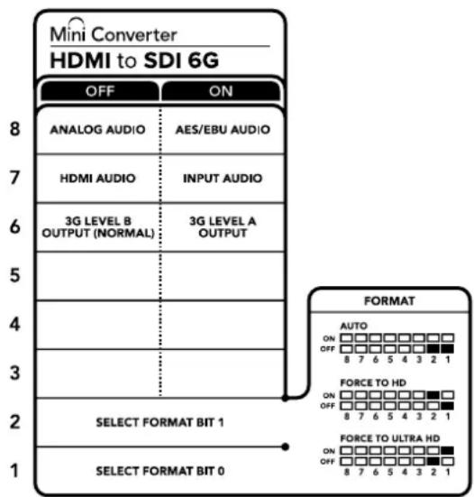
The switch legend on the base of your converter gives you all the information you need to change conversion settings.
Blackmagic Converters Setup Settings
The Converters Setup utility can be used to change settings and update your Mini Converter's software. You can access these settings by moving between the 'audio,' and 'about' tabs. The 'about' tab is detailed in the 'changing settings' section in this manual. The 'audio' tab for Mini Converter HDMI to SDI 6G contains the following settings.
Input Levels menu
This menu allows you to adjust the gain on the audio input. You can adjust audio levels independently per channel, or together by clicking the 'link' icon next to their sliders. To reset all audio levels back to 0 dB click the 'reset' button at the top of the 'input levels' menu.

Use the 'audio' tab in Converters Setup to adjust audio levels.
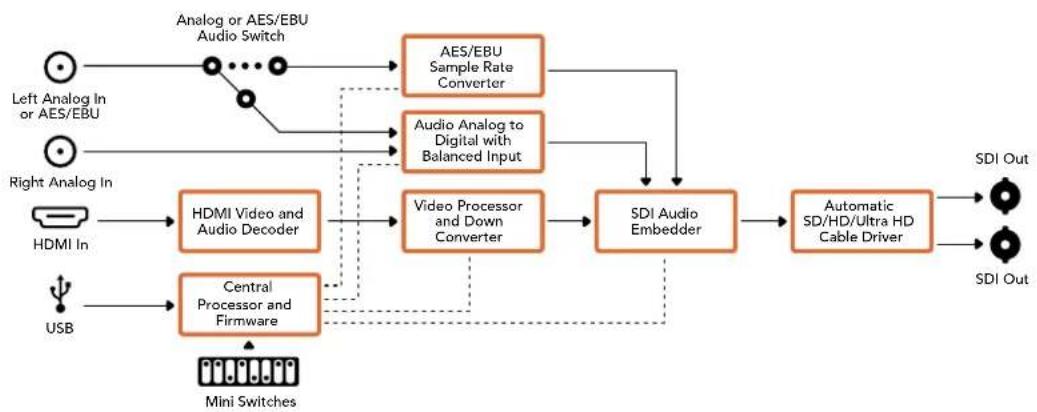
Mini Converter HDMI to SDI 6G Block Diagram
Mini Converter SDI to Analog
Your Blackmagic Mini Converter SDI to Analog converts from SD/HD-SDI to analog component, NTSC and PAL video out, plus balanced AES/EBU and analog audio out. Your converter easily connects to analog video monitors and decks such as Betacam SP and VHS. A hardware down converter lets you connect HD-SDI video to SD analog equipment. You can even output pairs of analog audio from 16 de-embedded SDI audio channels.

Connectors
1 Y or NTSC/PAL
Analog component Y, or composite NTSC/PAL output on a BNC connector.
2 B-Y or S-VIDEO Y
Analog component B-Y, or S-Video Y output BNC connector.
3 R-Y or S-VIDEO C
Analog component R-Y, or S-Video C output BNC connector.
4 L - ANALOG or AES/EBU
Balanced left channel analog audio, or AES/EBU digital audio output on a 1/4" jack connector.
5 R-ANALOG
Balanced right channel analog audio output 1/4" jack connector.
6 MINI-B USB PORT
Connects to the Converters Setup software via your Mac OS X or Windows computer. The Mini Converter's internal software is also updated using the USB port.
7 SDI OUT
SDI video output on a BNC connector.
8 ALT SDI IN
Redundant SDI input is provided as an optional back up.
9 SDIN
Primary SDI input.
10 POWER +12V
12 volt power supply input.
Switches
Switch 8 - Analog Audio, AES/EBU Audio
Set switch 8 to OFF to select balanced analog audio, or to ON for digital AES/EBU audio output.
Switch 7-7.5 IRE -0.0 IRE
The USA and countries using NTSC with 7.5 setup should set switch 7 to OFF. If you're working in countries not using 7.5 setup, set switch 7 to ON. This setting only affects composite or S-Video outputs.
Switch 6 - SMPTE Levels - Betacam Levels
Set switch 6 to OFF for SMPTE levels, or ON for Betacam levels. SMPTE levels are more common and even Betacam SP decks can use SMPTE levels, so only switch this to Betacam if you are sure that Betacam levels are being used.
Switch 5 - Component, Composite or S-Video
Set switch 5 to OFF to select analog component video output, or ON for composite and S-Video outputs.
To display the HD video input on the S-Video and composite outputs, down conversion must be set to ON. Component analog video supports both HD and SD video.
Switch 4 - SDI Audio De-Embed B it 2
Switches 4, 3 and 2 are grouped together to provide 8 ON/OFF combinations. Having eight different combinations allows eight independent pairs of audio channels to be de-embedded from your SDI input.
Switch 3 - SDI Audio De-Embed Bit 1
See switch 4 description.
Switch 2 - SDI Audio De-Embed Bit 0
See switch 4 description.
Switch 1 - Processing Off - Processing On
Down convert HD to SD with 3 types of aspect ratios by cycling through switch 1. For example, each time you cycle between Off and On you apply anamorphic, center cut or letterbox aspect ratios. Leaving switch 1 set to OFF bypasses the down converter and outputs in HD.
When connected to Blackmagic Converters Setup via USB, your down conversion settings are controlled by the software. If you want the converter to remember your software settings, disconnect from the computer, power cycle your converter and set your down conversion using switch 1.
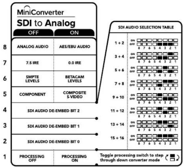
The switch legend on the base of your converter gives you all the information you need to change conversion settings.
Mini Switch Settings Example
Experiment with the switches by setting your Blackmagic Mini Converter to output high definition component video and analog audio channels 1 and 2 by setting switches 8, 5, 4, 3 and 2 to the OFF position.
SDI Audio Selection Table
| Audio Channels Switch 4 Switch 3 Switch 2 Switch Diagram | |||
| 1 and 2 OFF OFF OFF | ON OFF 8 7 6 5 4 3 2 1 | ||
| 3 and 4 OFF OFF ON | ON OFF 8 7 6 5 4 3 2 1 | ||
| 5 and 6 OFF ON OFF | ON OFF 8 7 6 5 4 3 2 1 | ||
| 7 and 8 OFF ON ON | ON OFF 8 7 6 5 4 3 2 1 | ||
| 9 and 10 ON OFF OFF | ON OFF 8 7 6 5 4 3 2 1 | ||
| 11 and 12 ON OFF ON | ON OFF 8 7 6 5 4 3 2 1 | ||
| 13 and 14 ON ON OFF | ON OFF 8 7 6 5 4 3 2 1 | ||
| 15 and 16 ON ON ON | ON OFF 8 7 6 5 4 3 2 1 | ||
Blackmagic Converters Setup Settings
The Converters Setup utility can be used to change settings and update your Mini Converter's software. You can access these settings by moving between the 'video,' 'audio,' and 'about' tabs.
The 'about' tab is detailed in the 'changing settings' section in this manual.
The 'video' tab for Mini Converter SDI to Analog contains the following settings.
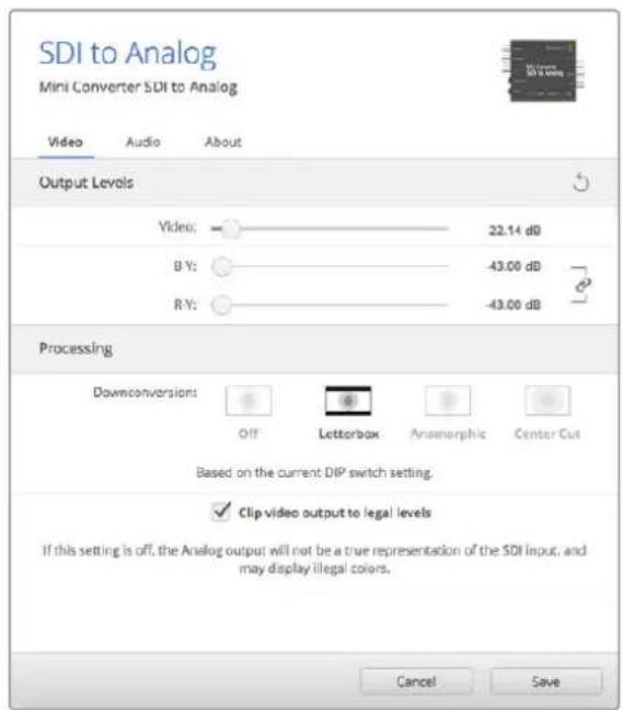
Use the 'video' tab in Converters Setup to adjust analog video levels and processing settings.
Processing menu
This menu allows you to set the aspect ratio of down converted video. The options are letterbox, anamorphic, center cut or no processing.
The 'clip video output to legal levels' checkbox controls clipping of your SDI input to ensure that it stays within HDMI legal levels and should be kept on by default.
Output Levels menu
This lets you set the luminance and chroma levels, and the B-Y and R-Y component levels independently.
The 'audio' tab for Mini Converter SDI to Analog contains the following settings.
Output Levels menu
This menu allows you to adjust the gain on the audio output. You can adjust audio levels independently per channel, or together by clicking the 'link' icon next to their sliders. To reset all audio levels back to 0 dB click the 'reset' button at the top of the 'output levels' menu.

Use the 'audio' tab in Converters Setup to adjust analog audio levels.
Mini Converter SDI to Analog Block Diagram
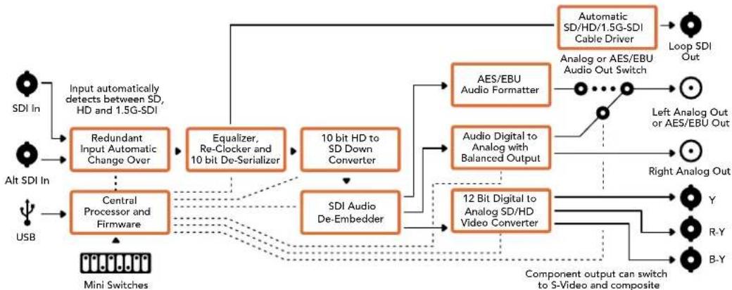
Mini Converter SDI to Analog 4K
Your Mini Converter SDI to Analog 4K and the SDI to Analog 4K Heavy Duty model can convert from SD/HD/3G/6G-SDI to analog component, NTSC and PAL video out, plus balanced AES/ EBU and analog audio out. This down converter lets you connect up to 6G-SDI video to SD or HD analog equipment and easily connects to video monitors and decks such as Betacam SP and VHS. You can even output pairs of analog audio from 16 de-embedded SDI audio channels.
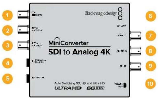
Connectors
1 Y or NTSC/PAL
Analog component Y or composite NTSC/PAL output BNC connector.
2 B-Y or S-VIDEO Y
Analog component B-Y, or S-Video Y output BNC connector.
3 R-Y or S-VIDEO C
Analog component R-Y, or S-Video C output BNC connector.
4 L - ANALOG or AES/EBU
Balanced left channel analog audio, or AES/EBU digital audio output 1/4" jack connector.
5 R-ANALOG
Balanced right channel analog audio output 1/4" jack connector.
6 MINI-B USB PORT
Connects to the Converters Setup software via your Mac OS X or Windows computer. The Mini Converter's internal software is also updated using the USB port.
7 SDI OUT
SDI video output BNC connector.
8 ALT SDI IN
Redundant SDI input is provided as an optional back up.
9 SDI IN
Primary SDI input.
10 POWER +12V
12 volt power supply input.
Switches
TIP On the Mini Converter Heavy Duty model, the switches are protected by a rubber dust cover. Simply lift the edge of the cover to access the switches.
Mini Converter SDI to Analog 4K's switches provide the following settings:
Switch 8 - Analog Audio, AES/EBU Audio
Set switch 8 to OFF to select balanced analog audio, or to ON for digital AES/EBU audio output.
Switch 7 - 7.5 IRE - 0.0 IRE
The USA and countries using NTSC with 7.5 setup should set switch 7 to OFF. If you're working in countries not using 7.5 setup, set switch 7 to ON. This setting only affects composite or S-Video outputs.
Switch 6 - SMPTE Levels - Betacam Levels
Set switch 6 to OFF for SMPTE levels, or ON for Betacam levels. SMPTE levels are more common and even Betacam SP decks can use SMPTE levels, so only switch this to Betacam if you are sure that Betacam levels are being used.
Switch 5 - Component, Composite or S-Video
Set switch 5 to OFF to select analog component video output, or ON for composite and S-Video outputs.
To display the HD video input as SD on the S-Video and composite outputs, down conversion must be set to ON. Component analog video supports both HD and SD video.
Switch 4, 3 and 2 - SDI Audio De-Embed
Switches 4, 3 and 2 are grouped together to provide 8 ON/OFF combinations. Having eight different combinations allows eight independent pairs of audio channels to be de-embedded from your SDI input.
Switch 1 - Processing Off - Processing On
Down conversion with 3 types of aspect ratios by cycling through switch 1. Each time you cycle between Off and On you apply anamorphic, center cut or letterbox aspect ratios.
For both HD and Ultra HD input, set switch to OFF to output HD analog via the component outputs.
Set switch to ON and Ultra HD input downconverts to either analog PAL/NTSC or HD component depending on the other switch settings. 4K DCI will be cropped on the component HD output.
An ON setting with HD input will be downconverted to analog PAL/NTSC or component depending on the other switch settings.
When connected to Blackmagic Converters Setup via USB, your down conversion settings are controlled by the software. If you want the converter to remember your software settings, disconnect from the computer, power cycle your converter and set your down conversion using switch 1.

The switch legend on the base of your converter gives you all the information you need to change conversion settings.
Mini Switch Settings Example:
Experiment with the switches by setting your Blackmagic Mini Converter to output high definition component video and analog audio channels 1 and 2 by setting switches 8, 5, 4, 3 and 2 to the OFF position.
Audio Selection Table
| Audio Channels Switch 4 Switch 3 Switch 2 Switch Diagram | |||
| 1 and 2 OFF OFF OFF | ON OFF 8 7 6 5 4 3 2 1 | ||
| 3 and 4 OFF ON | ON OFF 8 7 6 5 4 3 2 1 | ||
| 5 and 6 OFF ON | ON OFF 8 7 6 5 4 3 2 1 | ||
| 7 and 8 OFF ON | ON OFF 8 7 6 5 4 3 2 1 | ||
| 9 and 10 ON OFF OFF | ON OFF 8 7 6 5 4 3 2 1 | ||
| 11 and 12 ON OFF ON | ON OFF 8 7 6 5 4 3 2 1 | ||
| 13 and 14 ON ON OFF | ON OFF 8 7 6 5 4 3 2 1 | ||
| 15 and 16 ON ON ON | ON OFF 8 7 6 5 4 3 2 1 | ||
Blackmagic Converters Setup Settings
The Converters Setup utility can be used to change settings and update your Mini Converter's software. You can access these settings by moving between the 'video,' 'audio,' and 'about' tabs.
The 'about' tab is detailed in the 'changing settings' section in this manual.
The 'video' tab for Mini Converter SDI to Analog 4K contains the following settings.
Output Levels menu
This lets you set the luminance and chroma levels, and the B-Y and R-Y component levels independently.
Processing menu
This menu allows you to set the aspect ratio of down converted video. The options are letterbox, anamorphic, center cut or no processing.
The 'clip video output to legal levels' checkbox controls clipping of your SDI input to ensure that it stays within HDMI equal levels and should be kept on by default.
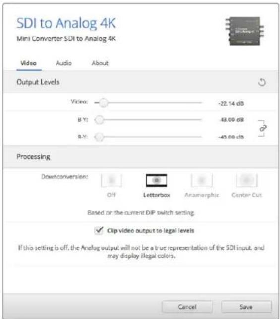
Use the 'video' tab in Converters Setup to adjust analog video levels and processing settings.
The 'audio' tab for Mini Converter SDI to Analog 4K contains the following settings.
Output Levels menu
This menu allows you to adjust the gain on the audio input. You can adjust audio levels independently per channel, or together by clicking the 'link' icon next to their sliders. To reset all audio levels back to 0 dB click the 'reset' button at the top of the 'output levels' menu.

Use the 'audio' tab in Converters Setup to adjust analog audio levels.
Mini Converter SDI to Analog 4K Block Diagram
Mini Converter Analog to SDI
With your Mini Converter Analog to SDI and the Analog to SDI Heavy Duty model you can convert video and audio from analog equipment such as Betacam SP decks, HDV cameras and game consoles to SD/HD-SDI video. A choice of analog and digital formats is supported, including component SD/HD, S-Video, or composite NTSC and PAL. The converter's HD-SDI outputs include the option to embed digital AES/EBU or analog audio.
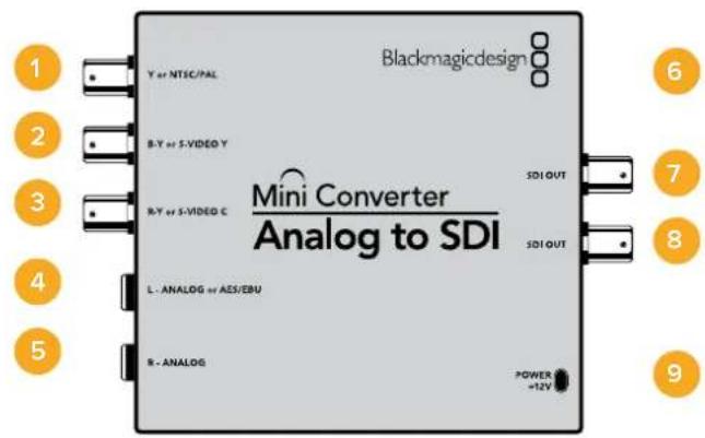
Connectors
1 Y or NTSC/PAL
Analog component Y, or composite NTSC/PAL input BNC connector.
2 B-Y or S-VIDEO Y
Analog component B-Y, or S-Video Y input BNC connector.
3 R-Y or S-VIDEO C
Analog component R-Y, or S-Video C input BNC connector.
4 L-ANALOG or AES/EBU
Balanced left channel analog audio, or AES/EBU digital audio input 1/4" jack connector.
5 R-ANALOG
Balanced right channel analog audio input 1/4" jack connector.
6 MINI-B USB PORT
Connects to the Converters Setup software via your Mac OS X or Windows computer. The Mini Converter's internal software is also updated using the USB port.
7 SDI OUT
SDI video output BNC connector.
8 SDI OUT
Second SDI output.
9 POWER +12V
12 volt power supply input.
Switches
TIP On the Mini Converter Heavy Duty model, the switches are protected by a rubber dust cover. Simply lift the edge of the cover to access the switches.
Mini Converter Analog to SDI's switches provide the following settings:
Switch 8 - Analog Audio, AES/EBU Audio
Set switch 8 to OFF to select balanced analog audio, or to ON for digital AES/EBU audio input.
Switch 7-7.5 IRE -0.0 IRE
The USA and countries using NTSC with 7.5 setup should set switch 7 to OFF. If you're working in countries not using 7.5 setup, for example Japan, set switch 7 to ON. This setting only affects composite or S-Video outputs.
Switch 6 - SMPTE Levels - Betacam Levels
This setting selects between SMPTE or Betacam video levels. Set switch 6 to OFF for SMPTE levels, or to ON for Betacam levels. SMPTE levels are more common and even Betacam SP decks can use SMPTE levels so only switch this to Betacam if you are sure that Betacam levels are being used.
Switch 5 - Component, Composite or S-Video
Set switch 5 to OFF to select analog component video input, or to ON for composite video and S-Video analog inputs.
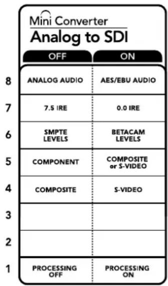
The switch legend on the base of your converter gives you all the information you need to change conversion settings.
Switch 4 - Composite - S-Video
Set switch 4 to OFF to select composite video input, or to ON for S-Video input.
Switch 1 - Processing Off - Processing On
This switch is not used.
Mini Switch Settings Example
Experiment with the switches by setting your Blackmagic Mini Converter to Component and Analog Audio input by setting switches 8 and 5 to the OFF position.
Blackmagic Converters Setup Settings
The Converters Setup utility can be used to change settings and update your Mini Converter's software. You can access these settings by moving between the 'video,' 'audio,' and 'about' tabs.
The 'about' tab is detailed in the 'changing settings' section in this manual.
The 'video' tab for Mini Converter Analog to SDI contains the following settings.
Input Levels menu
This lets you set the luminance and chroma levels, and the B-Y and R-Y component levels independently.
The 'audio' tab for Mini Converter Analog to SDI contains the following settings.
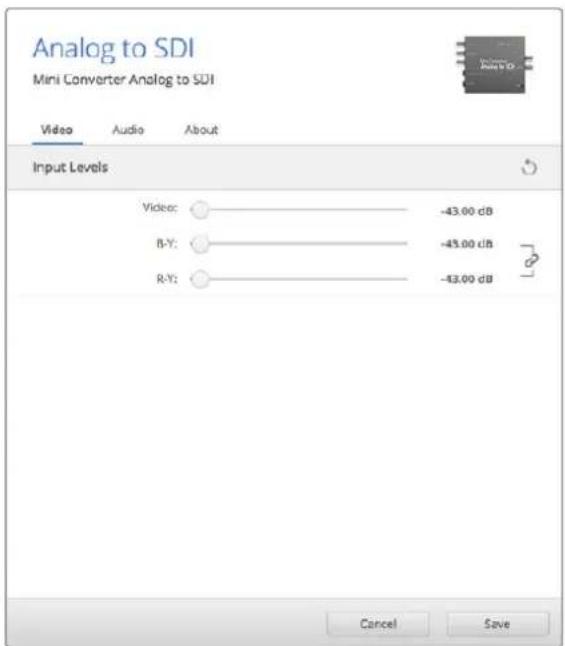
Use the 'video' tab in Converters Setup to adjust video levels.
Input Levels menu
This menu allows you to adjust the gain on the audio input. You can adjust audio levels independently per channel, or together by clicking the 'link' icon next to their sliders. To reset all audio levels back to 0 dB click the 'reset' button at the top of the 'input levels' menu.

Use the 'audio' tab in Converters Setup to adjust analog audio levels.
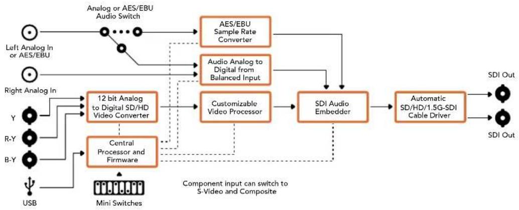
Mini Converter Analog to SDI Block Diagram
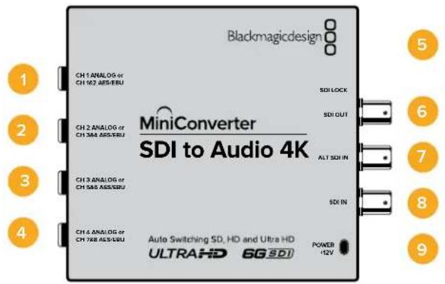
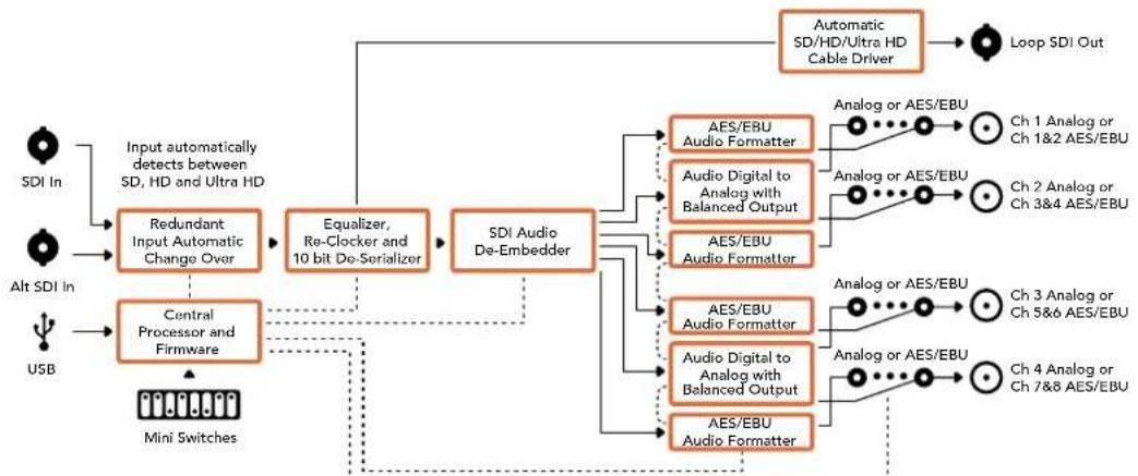
Mini Converter SDI to Audio
Your Mini Converter SDI to Audio can de-embed 4 channels of audio from any SDI video connection and output to 4 channels of analog audio or 8 channels of AES/EBU digital. Output to audio equipment such as audio mixers, analog decks and reference monitors. Additional SDI audio channels can be de-embedded by daisy chaining another Mini Converter SDI to Audio to your converter's SDI output.
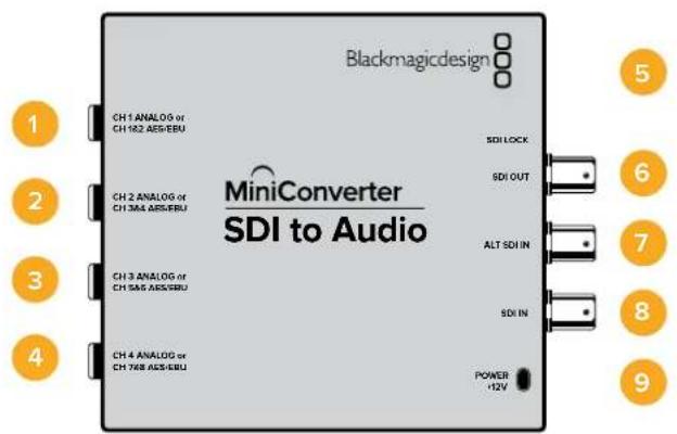
Connectors
1 CH 1 ANALOG or CH 1 & 2 AES/EBU
Balanced analog audio channel 1, or AES/EBU digital audio channels 1 and 2 output 1 / 4 jack connector.
2 CH 2 Analog or CH 3 & 4 AES/EBU
Balanced analog audio channel 2, or AES/EBU digital audio channels 3 and 4 output 1 / 4 jack connector.
3 CH 3 Analog or CH 5 & 6 AES/EBU
Balanced analog audio channel 3, or AES/EBU digital audio channels 5 and 6 output 1 / 4^ jack connector.
4 CH 4 Analog or CH 7 & 8 AES/EBU
Balanced analog audio channel 4, or AES/EBU digital audio channels 7 and 8 output 1 / 4 jack connector.
5 MINI-B USB PORT
Connects to the Converters Setup software via your Mac OS X or Windows computer. The Mini Converter's internal software is also updated using the USB port.
6 SDI OUT
Loop through SDI video output BNC connector.
7 ALT SDI IN
Redundant SDI input provided as an optional back up. When using both the SDI IN and ALT SDI IN, the ALT SDI IN will take over should the SDI IN signal fail. The SDI LOCK LED will flash indicating that the converter has switched to the ALT SDI IN.
8 SDI IN
Primary SDI input.
9 POWER +12V
12 volt power supply input.
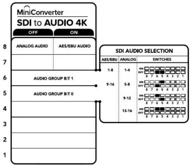
Switches
Mini Converter SDI to Audio's switches provide the following settings:
Switch 8 - Analog Audio, AES/EBU Audio
Set switch 8 to OFF to select balanced analog audio, or to ON for digital AES/EBU audio output.
Switch 6 - Audio Group Bit 1
Switches 6 and 5 are grouped together to provide four ON/OFF combinations. This allows up to 4 quadruplets of analog audio channels, or 2 sets of 8 AES/EBU audio channels, to be de-embedded from your SDI input.
Switch 5 - Audio Group Bit 0
See switch 6 description.
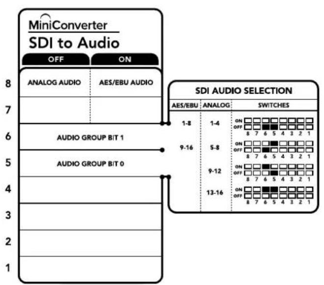
The switch legend on the base of your converter gives you all the information you need to change conversion settings.
Mini Switch Settings Example
Try experimenting with the switches. Select analog audio channels 1 to 4 by setting switches 8, 6 and 5 to the OFF position.
Audio Selection Tables
| Analog Audio Channels Switch 6 Switch 5 Switch Diagram | |||
| 1 to 4 OFF OFF | ON OFF 8 7 6 5 4 3 2 1 | ||
| 5 to 8 OFF ON | ON OFF 8 7 6 5 4 3 2 1 | ||
| 9 to 12 ON OFF | ON OFF 8 7 6 5 4 3 2 1 | ||
| 13 to 16 ON ON | ON OFF 8 7 6 5 4 3 2 1 | ||
| AES/EBU Channels Switch 6 Switch 5 Switch Diagram | |||
| 1 to 8 OFF OFF | ON OFF 8 7 6 5 4 3 2 1 | ||
| 9 to 16 OFF ON | ON OFF 8 7 6 5 4 3 2 1 | ||
Blackmagic Converters Setup Settings
The Converters Setup utility can be used to change settings and update your Mini Converter's software. You can access these settings by moving between the 'audio,' and 'about' tabs.
The 'about' tab is detailed in the 'changing settings' section in this manual.
The 'audio' tab for Mini Converter SDI to Audio contains the following settings.
Output Levels menu
This menu allows you to adjust the gain on the audio output. You can adjust audio levels independently per channel, or together as channel pairs by clicking the 'link' icon next to their sliders. To reset all audio levels back to 0 dB click the 'reset' button at the top of the 'output levels' menu.
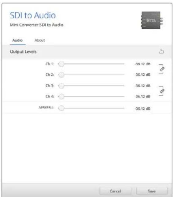
Use the 'audio' tab in Converters Setup to adjust audio levels.
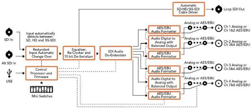
Mini Converter SDI to Audio Block Diagram
Mini Converter SDI to Audio 4K
With Mini Converter SDI to Audio 4K you can de-embed 4 channels of audio from any SDI video connection and output to 4 channels of analog audio or 8 channels of AES/EBU digital. Output to audio equipment such as audio mixers, analog decks and reference monitors. Additional SDI audio channels can be de-embedded by daisy chaining another Mini Converter SDI to Audio 4K to your converter's SDI output.
Connectors
1 CH 1 ANALOG or CH 1 & 2 AES/EBU
Balanced analog audio channel 1, or AES/EBU digital audio channels 1 and 2 output 1 / 4 jack connector.
2 CH 2 Analog or CH 3 & 4 AES/EBU
Balanced analog audio channel 2, or AES/EBU digital audio channels 3 and 4 output 1 / 4 jack connector.
3 CH 3 Analog or CH 5 & 6 AES/EBU
Balanced analog audio channel 3, or AES/EBU digital audio channels 5 and 6 output 1 / 4 jack connector.
4 CH 4 Analog or CH 7 & 8 AES/EBU
Balanced analog audio channel 4, or AES/EBU digital audio channels 7 and 8 output 1 / 4 jack connector.
5 MINI-B USB PORT
Connects to the Converters Setup software via your Mac OS X or Windows computer. The Mini Converter's internal software is also updated using the USB port.
6 SDI OUT
Loop through SDI video output BNC connector.
7 ALT SDI IN
Redundant SDI input provided as an optional back up. When using both the SDI IN and ALT SDI IN, the ALT SDI IN will take over should the SDI IN signal fail. The SDI LOCK LED will flash indicating that the converter has switched to the ALT SDI IN.
8 SDIN
Primary SDI input.
9 POWER +12V
12 volt power supply input.
Switches
Mini Converter SDI to Audio 4K switches provide the following settings:
Switch 8 - Analog Audio, AES/EBU Audio
Set switch 8 to OFF to select balanced analog audio, or to ON for digital AES/EBU audio output.
Switch 6 - Audio Group Bit 1
Switches 6 and 5 are grouped together to provide four ON/OFF combinations. This allows up to 4 quadruplets of analog audio channels, or 2 sets of 8 AES/EBU audio channels, to be de-embedded from your SDI input.
Switch 5 - Audio Group Bit 0
See switch 6 description.
Mini Switch Settings Example
Try experimenting with the switches. Select analog audio channels 1 to 4 by setting switches 8, 6 and 5 to the OFF position.
The switch legend on the base of your converter gives you all the information you need to change conversion settings.
Audio Selection Tables
| Analog Audio Channels Switch 6 Switch 5 Switch Diagram | ||
| 1 to 4 OFF OFF | ON OFF 8 7 6 5 4 3 2 1 | |
| 5 to 8 OFF ON | ON OFF 8 7 6 5 4 3 2 1 | |
| 9 to 12 ON OFF | ON OFF 8 7 6 5 4 3 2 1 | |
| 13 to 16 ON ON | ON OFF 8 7 6 5 4 3 2 1 | |
| AES/EBU Channels Switch 6 Switch 5 Switch Diagram | ||
| 1 to 8 OFF OFF | ON OFF 8 7 6 5 4 3 2 1 | |
| 9 to 16 OFF ON | ON OFF 8 7 6 5 4 3 2 1 | |
Blackmagic Converters Setup Settings
The Converters Setup utility can be used to change settings and update your Mini Converter's software. You can access these settings by moving between the 'audio,' and 'about' tabs.
The 'about' tab is detailed in the 'changing settings' section in this manual.
The 'audio' tab for Mini Converter SDI to Audio 4K contains the following settings.
Output Levels menu
This menu allows you to adjust the gain on the audio output. You can adjust audio levels independently per channel, or together as channel pairs by clicking the 'link' icon next to their sliders. To reset all audio levels back to 0 dB click the 'reset' button at the top of the 'output levels' menu.

Use the 'audio' tab in Converters Setup to adjust analog audio levels.
Mini Converter SDI to Audio 4K Block Diagram
Mini Converter Audio to SDI
Your Mini Converter Audio to SDI can embed four channels of analog audio, or eight channels of AES/EBU digital audio into any SDI video connection. You can use this Mini Converter to embed audio from equipment, such as audio mixers and analog decks, into SDI video connections for use with SDI routers and decks. Additional SDI audio channels can be embedded by daisy chaining another Mini Converter Audio to SDI to your converter's SDI output.
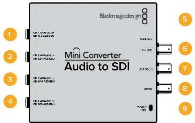
Connectors
1 CH1 Analog or CH 1 & 2 AES/EBU
Balanced analog audio channel 1, or AES/EBU digital audio channels 1 and 2 input 1 / 4 jack connector.
2 CH 2 Analog or CH 3 & 4 AES/EBU
Balanced analog audio channel 2, or AES/EBU digital audio channels 3 and 4 input 1 / 4 jack connector.
3 CH 3 Analog or CH 5 & 6 AES/EBU
Balanced analog audio channel 3, or AES/EBU digital audio channels 5 and 6 input 1 / 4 jack connector.
4 CH 4 Analog or CH 7 & 8 AES/EBU
Balanced analog audio channel 4, or AES/EBU digital audio channels 7 and 8 input 1 / 4^ jack connector.
5 Mini-B USB PORT
Connects to the Converters Setup software via your Mac OS X or Windows computer. The Mini Converter's internal software is also updated using the USB port.
6 SDI OUT
Loop through SDI video output BNC connector.
7 ALT SDI IN
Redundant SDI input provided as an optional back up. When using both the SDI IN and ALT SDI IN, the ALT SDI IN will take over should the SDI IN signal fail. The SDI LOCK LED will flash indicating that the converter has switched to the ALT SDI IN.
8 SDIN
Primary SDI input.
9 POWER +12V
12 volt power supply input.
Switches
Mini Converter Audio to SDI's switches provide the following settings:
Switch 8 - Analog Audio, AES/EBU Audio
Set switch 8 to OFF to select balanced analog audio, or to ON for digital AES/EBU audio input.
Switch 7 - Sample Rate Conversion, No Sample Rate Conversion
Set switch 7 to OFF to enable sample rate conversion, or ON to disable sample rate conversion. This switch should almost always be set to OFF to ensure audio is embedded at the correct sample rate for television.
When switch 7 is set to OFF this setting converts the sample rate of your analog or AES/EBU audio and embeds audio into the SDI output at a sample rate of 48kHz . When switch 7 is set to ON, sample rate conversion is disabled and audio is output at the original sample rate of your input audio.
Switch 6 - Audio Group Bit 1
Switches 6 and 5 are grouped together to provide four ON/OFF combinations. Having four different combinations allows up to four analog audio channels, or eight AES/EBU audio channels to be embedded in your SDI output.
Switch 5 - Audio Group Bit 0
See switch 6 description.
Audio Selection Table
| Analog Audio Channels Switch 6 Switch 5 Switch Diagram | ||
| 1 to 4 OFF OFF | ON OFF 8 7 6 5 4 3 2 1 | |
| 5 to 8 OFF ON | ON OFF 8 7 6 5 4 3 2 1 | |
| 9 to 12 ON OFF | ON OFF 8 7 6 5 4 3 2 1 | |
| 13 to 16 ON ON | ON OFF 8 7 6 5 4 3 2 1 | |
| AES/EBU Channels | Switch 6 Switch 5 Switch Diagram | |
| 1 to 8 OFF OFF | ON OFF 8 7 6 5 4 3 2 1 | |
| 9 to 16 OFF ON | ON OFF 8 7 6 5 4 3 2 1 | |
Embedding or Disabling Channels
Once you have selected your audio channels, use switches 4, 3, 2 and 1 to select which channels to embed or disable. The disable setting lets you avoid overwriting audio channels you wish to keep in the SDI signal.
For example, you can disable analog audio channel 1 or AES/EBU channels 1 and 2 by setting switch 1 to the ON position. Alternatively, you can embed the audio channels by setting switch 1 to the OFF position.
Audio Channel De-Embed or Disable Settings
| Switch Setting Audio Channels | |
| 4 | ON Disable analog CH 4, AES/EBU CH 7 and 8 |
| OFF Embed analog CH 4, AES/EBU CH 7 and 8 | |
| 3 | ON Disable analog CH 3, AES/EBU CH 5 and 6 |
| OFF Embed analog CH 3, AES/EBU CH 5 and 6 | |
| 2 | ON Disable analog CH 2, AES/EBU CH 3 and 4 |
| OFF Embed analog CH 2, AES/EBU CH 3 and 4 | |
| 1 | ON Disable analog CH 1, AES/EBU CH 1 and 2 |
| OFF Embed analog CH 1, AES/EBU CH 1 and 2 | |
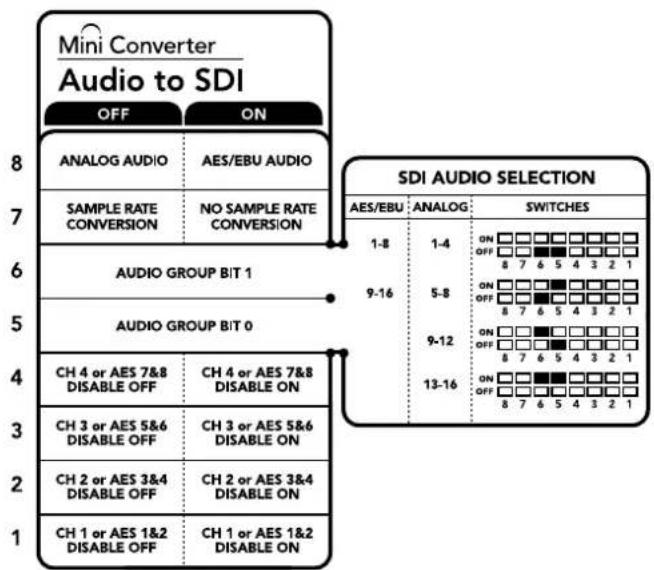
The switch legend on the base of your converter gives you all the information you need to change conversion settings.
Mini Switch Settings Example:
Try experimenting with the switches. Select analog audio channels 1 to 4 by setting switches 8, 6 and 5 to the OFF position.
Blackmagic Converters Setup Settings
The Converters Setup utility can be used to change settings and update your Mini Converter's software. You can access these settings by moving between the 'audio,' and 'about' tabs.
The 'about' tab is detailed in the 'changing settings' section in this manual.
The 'audio' tab for Mini Converter Audio to SDI contains the following settings.
Input Levels menu
This menu allows you to adjust the gain on the audio input. You can adjust audio levels independently per channel, or together as channel pairs by clicking the 'link' icon next to their sliders. To reset all audio levels back to 0 dB click the 'reset' button at the top of the 'output levels' menu.

Use the 'audio' tab in Converters Setup to adjust analog audio levels.
Mini Converter Audio to SDI Block Diagram
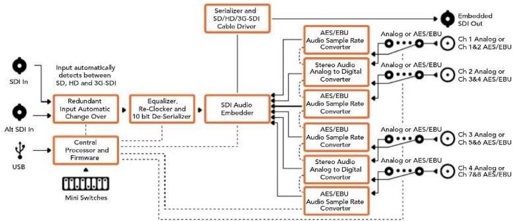
Mini Converter Audio to SDI 4K
Your Mini Converter Audio to SDI 4K can embed four channels of analog audio, or eight channels of AES/EBU digital audio into any SDI video connection. You can use this Mini Converter to embed audio from equipment, such as audio mixers and analog decks, into SDI video connections for use with SDI routers and decks. Additional SDI audio channels can be embedded by daisy chaining another Mini Converter Audio to SDI 4K to your converter's SDI output.
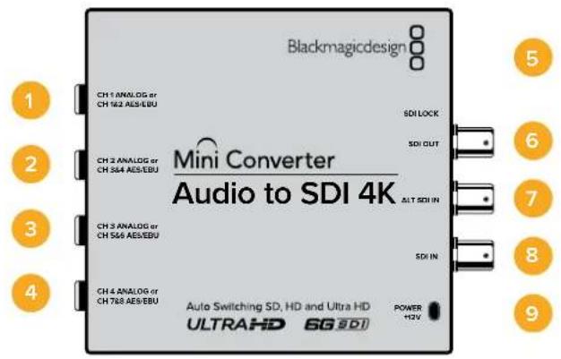
Connectors
1 CH 1 Analog or CH 1 & 2 AES/EBU
Balanced analog audio channel 1, or AES/EBU digital audio channels 1 and 2 input 1 / 4 jack connector.
2 CH 2 Analog or CH 3 & 4 AES/EBU
Balanced analog audio channel 2, or AES/EBU digital audio channels 3 and 4 input 1 / 4 jack connector.
3 CH 3 Analog or CH 5 & 6 AES/EBU
Balanced analog audio channel 3, or AES/EBU digital audio channels 5 and 6 input 1 / 4 jack connector.
4 CH 4 Analog or CH 7 & 8 AES/EBU
Balanced analog audio channel 4, or AES/EBU digital audio channels 7 and 8 input 1 / 4 jack connector.
5 Mini-B USB PORT
Connects to the Converters Setup software via your Mac OS X or Windows computer. The Mini Converter's internal software is also updated using the USB port.
6 SDI OUT
Loop through SDI video output on a BNC connector.
7 ALT SDI IN
Redundant SDI input provided as an optional back up. When using both the SDI IN and ALT SDI IN, the ALT SDI IN will take over should the SDI IN signal fail. The SDI LOCK LED will flash indicating that the converter has switched to the ALT SDI IN.
8 SDIN
Primary SDI input.
9 POWER +12V
12 volt power supply input.
Switches
Mini Converter Audio to SDI 4K switches provide the following settings:
Switch 8 - Analog Audio, AES/EBU Audio
Set switch 8 to OFF to select balanced analog audio, or to ON for digital AES/EBU audio input.
Switch 7 - Sample Rate Conversion, No Sample Rate Conversion
Set switch 7 to OFF to enable sample rate conversion, or ON to disable sample rate conversion. This switch should almost always be set to OFF to ensure audio is embedded at the correct sample rate for television.
When switch 7 is set to OFF this setting converts the sample rate of your analog or AES/EBU audio and embeds audio into the SDI output at a sample rate of 48kHz . When switch 7 is set to ON, sample rate conversion is disabled and audio is output at the original sample rate of your input audio.
Switch 6 - Audio Group Bit 1
Switches 6 and 5 are grouped together to provide four ON/OFF combinations. Having four different combinations allows up to four analog audio channels, or eight AES/EBU audio channels to be embedded in your SDI output.
Switch 5 - Audio Group Bit 0
See switch 6 description.
Audio Selection Table
| Analog Audio Channels Switch 6 Switch 5 Switch Diagram | |||
| 1 to 4 OFF OFF | ON OFF 8 7 6 5 4 3 2 1 | ||
| 5 to 8 OFF ON | ON OFF 8 7 6 5 4 3 2 1 | ||
| 9 to 12 ON OFF | ON OFF 8 7 6 5 4 3 2 1 | ||
| 13 to 16 ON ON | ON OFF 8 7 6 5 4 3 2 1 | ||
| AES/EBU Channels Switch 6 Switch 5 Switch Diagram | |||
| 1 to 8 OFF | OFF | ON OFF 8 7 6 5 4 3 2 1 | |
| 9 to 16 OFF | ON | ON OFF 8 7 6 5 4 3 2 1 | |
Embedding or Disabling Channels
Once you have selected your audio channels, use switches 4, 3, 2 and 1 to select which channels to embed or disable. The disable setting lets you avoid overwriting audio channels you wish to keep in the SDI signal.
For example, you can disable analog audio channel 1 or AES/EBU channels 1 and 2 by setting switch 1 to the ON position. Alternatively, you can embed the audio channels by setting switch 1 to the OFF position.
Audio Channel De-Embed or Disable Settings
| Switch Setting Audio Channels | |
| 4 | ON Disable analog CH 4, AES/EBU CH 7 and 8 |
| OFF Embed analog CH 4, AES/EBU CH 7 and 8 | |
| 3 | ON Disable analog CH 3, AES/EBU CH 5 and 6 |
| OFF Embed analog CH 3, AES/EBU CH 5 and 6 | |
| 2 | ON Disable analog CH 2, AES/EBU CH 3 and 4 |
| OFF Embed analog CH 2, AES/EBU CH 3 and 4 | |
| 1 | ON Disable analog CH 1, AES/EBU CH 1 and 2 |
| OFF Embed analog CH 1, AES/EBU CH 1 and 2 | |
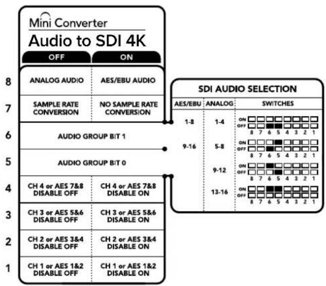
The switch legend on the base of your converter gives you all the information you need to change conversion settings.
Mini Switch Settings Example
Try experimenting with the switches. Select analog audio channels 1 to 4 by setting switches 8, 6 and 5 to the OFF position.
Blackmagic Converters Setup Settings
The Converters Setup utility can be used to change settings and update your Mini Converter's software. You can access these settings by moving between the 'audio,' and 'about' tabs.
The 'about' tab is detailed in the 'changing settings' section in this manual.
The 'audio' tab for Mini Converter Audio to SDI 4K contains the following settings.
Input Levels menu
This menu allows you to adjust the gain on the audio input. You can adjust audio levels independently per channel, or together as channel pairs by clicking the 'link' icon next to their sliders. To reset all audio levels back to 0 dB click the 'reset' button at the top of the 'output levels' menu.

Use the 'audio' tab in Converters Setup to adjust analog audio levels.
Mini Converter Audio to SDI 4K Block Diagram
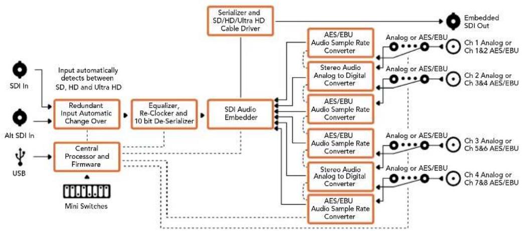
Mini Converter Optical Fiber
With Mini Converter Optical Fiber you can convert SDI to Optical Fiber and Optical Fiber to SDI simultaneously. Mini Converter Optical Fiber automatically switches between SD/HD/3G-SDI video standards and both directions are completely independent. Use this converter if you need to send and receive SDI signals over longer distances than traditional SDI cables will support. SD video can be sent up to 45 km or 147000 feet using optical fiber, compared to just 300 feet with copper SDI cables. 3G-SDI can be sent up to 25 km away!
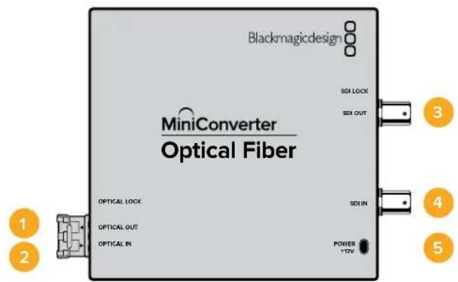
Connectors
1 Optical Out
Optical fiber output supports a single mode optical fiber cable with LC connector.
2 Optical In
Optical fiber input supports a single mode optical fiber cable with LC connector.
3 3G-SDI Out
SDI video output on a BNC connector for connection to traditional SDI equipment.
4 3G-SDI In
SDI input on a BNC connector for connection to traditional SDI equipment.
5 Power +12V
12 volt power supply input.
Mini Converter Optical Fiber Block Diagram
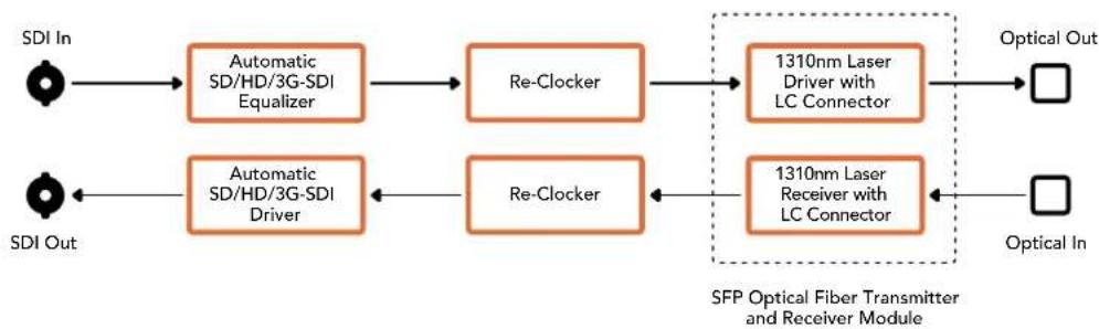
Mini Converter Optical Fiber 4K
Convert SD/HD and single link 6G-SDI to Optical Fiber and Optical Fiber to SD/HD and single link 6G-SDI simultaneously. Mini Converter Optical Fiber 4K automatically switches between SD/HD/3G/6G-SDI video standards and both directions are completely independent. Use this converter if you need to send and receive SDI signals over longer distances than traditional SDI cables will support. SD video can be sent up to 45km or 147000 feet using optical fiber, compared to just 300 feet with copper SDI cables. 6G-SDI can be sent up to 12km away!
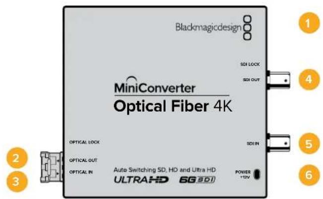
Connectors
1 Mini-B USB Port
The Mini Converter's internal software is updated using the USB port.
2 Optical Out
Optical fiber output supports a single mode optical fiber cable with LC connector.
3 Optical In
Optical fiber input supports a single mode optical fiber cable with LC connector.
4 SDI Out
SDI video output on a BNC connector for connection to traditional SDI equipment.
5 SDIn
SDI input on a BNC connector for connection to traditional SDI equipment.
6 Power +12V
12 volt power supply input.
Mini Converter Optical Fiber 4K Block Diagram
Mini Converter Optical Fiber 12G
This converter converts SD and HD video up to 12G-SDI to optical fiber and the other way around simultaneously.
The socket for the SFP type optical fiber module can be fitted with a compatible SFP optical fiber module that supports up to 3G, 6G or 12G-SDI video.
Your converter automatically detects the video input format and sets the output format to match. Both directions are completely independent.
This converter is helpful if you need to send and receive SDI signals over longer distances than traditional SDI cables will support. For example, SD video can be sent up to 45 km or 147,000 feet using optical fiber, compared to just 300 feet with copper SDI cables. 12G-SDI can be sent up to 6 km away!
Connectors
1 Optical Out
Optical fiber output supports a single mode optical fiber cable with LC connector.
2 Optical In
Optical fiber input supports a single mode optical fiber cable with LC connector.
3 SDI Out
SDI video output on a BNC connector for connection to SDI equipment.
4 SDIn
SDI input on a BNC connector for connection to SDI equipment.
5 Power +6 to 36V
6-36 volt power supply input. The support screw can be secured to the unit's power connector to prevent accidental disconnection.
Mini Converter Optical Fiber 12G Block Diagram
Mini Converter Quad SDI to HDMI 4K
Your Mini Converter Quad SDI to HDMI 4K can connect single link, dual link and quad link SDI Ultra HD to the latest Ultra HD projectors and televisions that support Ultra HD over a single HDMI link. You can also convert any of the following inputs to HDMI:
SD SDI
HD-SDI
- Singlelink 3G-SDI
- Singlelink 6G-SDI
Duaillink HD-SDI
Dual link 3G-SDI Ultra HD
- Quad link HD-SDI Ultra HD
If the HDMI output detects an HD monitor or HDTV, the output signal is automatically downconverted. Only use inputs 1 and 2 with a valid dual link signal.
Connectors
Supported formats are listed under each SDI input:
1 SDIn 1
SD/HD-SDI
- Single link 3G-SDI
- Single link 6G-SDI
Dual link HD-SDI channel A
Dual link 3G-SDI Ultra HD channel A
- Quad link HD-SDI Ultra HD channel A
2 SDIn 2
Dual link HD-SDI channel B
Dual link 3G-SDI Ultra HD channel B
- Quad link HD-SDI Ultra HD channel B
3 SDIn 3
- Quad link HD-SDI Ultra HD channel C
4 SDIn 4
- Quad link HD-SDI Ultra HD channel D
5 Mini-B USB port
Connects to the Converters Setup software via your Mac OS X or Windows computer.
The Mini Converter's internal software is also updated using the USB port.
6HDMI
HDMI type A video output.
7 Power +12V
12 volt power supply input.
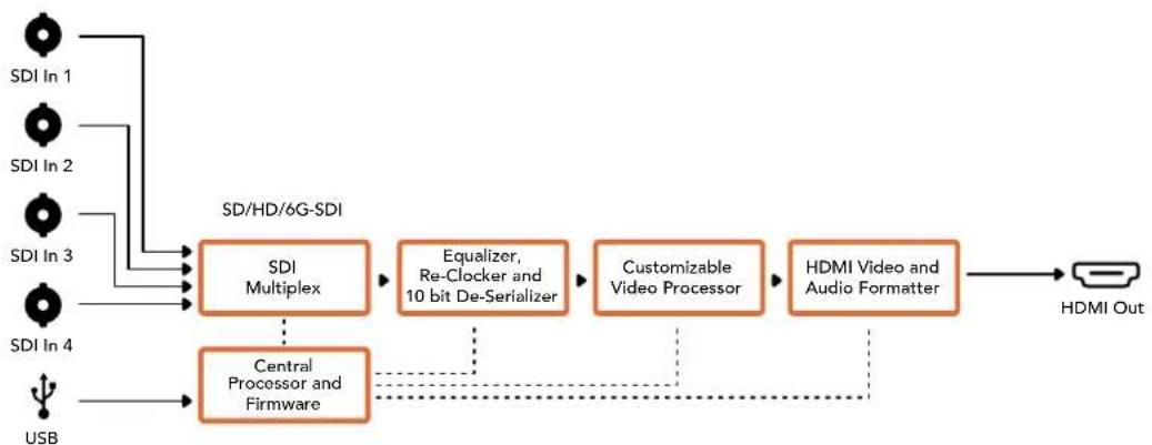
Mini Converter Quad SDI to HDMI 4K Block Diagram
Mini Converter SDI Distribution
With Mini Converter SDI Distribution you can output your SDI signal to eight SDI devices simultaneously, such as decks, monitor walls and switchers. Whenever the video input changes between SD-SDI, HD-SDI and 3G-SDI video formats, Mini Converter SDI Distribution automatically switches the 8 re-clocked outputs to match with support for ASI, ancillary data and embedded audio formats.
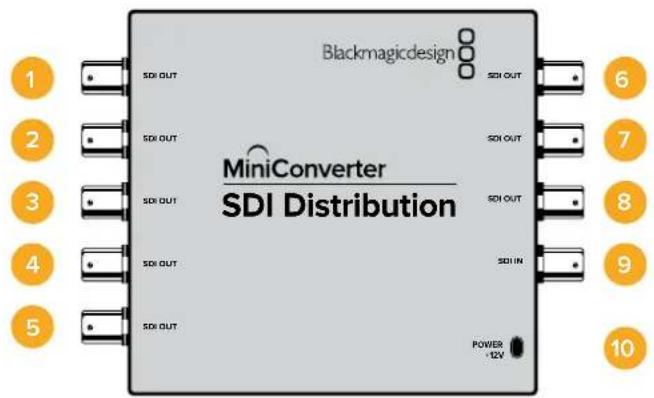
Connectors
1-8 SDI Out
SDI video outputs on BNC connectors.
9SDlIn
SDI input.
10 Power +12V
12 volt power supply input.
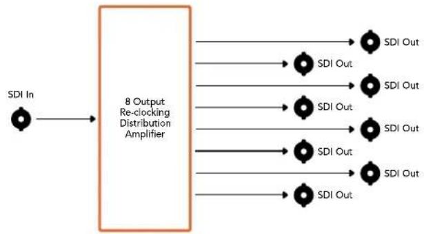
Mini Converter SDI Distribution Block Diagram
Mini Converter SDI Distribution 4K
Your Mini Converter SDI Distribution 4K outputs your SDI signal to eight SDI devices simultaneously, such as decks, monitor walls and switchers. Whenever the video input changes between SD/ HD/3G/6G-SDI video formats, Mini Converter SDI Distribution 4K automatically switches the 8 re-clocked outputs to match, with support for ASI, ancillary data and embedded audio formats.
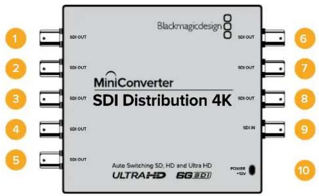
Connectors
1-8 SDI Out
SDI video outputs on BNC connectors.
9SDlIn
SDI input.
10 Power +12V
12 volt power supply input.
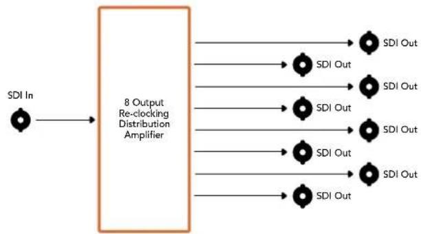
Mini Converter SDI Distribution 4K Block Diagram
Mini Converter SDI Multiplex 4K
Your Mini Converter SDI Multiplex 4K can perform the following conversions:
- Distribute an SD/HD and 6G-SDI signal to all four outputs.
- Distribute a dual link HD-SDI signal to all four 3G-SDI outputs.
- Single link 3G-SDI to dual link HD-SDI. The dual link output is distributed on both pairs of outputs.
- Single link 6G-SDI to dual link 3G-SDI or Quad link 1.5G-SDI.
- Quad link HD-SDI Ultra HD to single link 6G-SDI, or dual link 3G-SDI Ultra HD so you can connect existing Ultra HD sources to dual link Ultra HD displays. The dual link output is distributed on both pairs of outputs.
- Dual link 3G-SDI to single link 6G-SDI.
- Dual link 3G-SDI Ultra HD to quad link HD-SDI Ultra HD so you can connect the latest dual link Ultra HD sources to existing quad link Ultra HD displays.
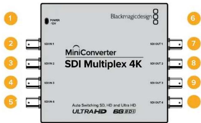
Connectors
1 Power +12V
12 volt power supply input
Supported formats for each SDI input
2 SDIn1
SD/HD-SDI
- Single link 3G-SDI
- Single link 6G-SDI
Dual link HD-SDI channel A
Dual link 3G-SDI Ultra HD channel A
- Quad link HD-SDI Ultra HD channel A
3 SDIn 2
Dual link HD-SDI channel B
Dual link 3G-SDI Ultra HD channel B
- Quad link HD-SDI Ultra HD channel B
4 SDIn 3
- Quad link HD-SDI Ultra HD channel C
5 SDIn 4
- Quad link HD-SDI Ultra HD channel D
6 Mini-B USB port
Connects to the Converters Setup software via your Mac OS X or Windows computer.
The Mini Converter's internal software can also be updated using the USB port.
Supported formats are listed under each SDI output:
7 SDI Out 1
SD/HD-SDI
- Single link 3G-SDI
- Single link 6G-SDI
Dual link HD-SDI channel A
Dual link 3G-SDI Ultra HD channel A
- Quad link HD-SDI Ultra HD channel A
8 SDI Out 2
SD/HD-SDI
- Single link 3G-SDI
- Single link 6G-SDI
Dual link HD-SDI channel B
Dual link 3G-SDI Ultra HD channel B
- Quad link HD-SDI Ultra HD channel B
9 SDI Out 3
SD/HD-SDI
- Single link 3G-SDI
- Single link 6G-SDI
Dual link HD-SDI channel A
Dual link 3G-SDI Ultra HD channel A
- Quad link HD-SDI Ultra HD channel C
10 SDI Out 4
SD/HD-SDI
- Single link 3G-SDI
- Single link 6G-SDI
Dual link HD-SDI channel B
Dual link 3G-SDI Ultra HD channel B
- Quad link HD-SDI Ultra HD channel D
Switches
Mini Converter SDI Multiplex 4K's switches provide the following settings:
Switches 8, 7 and 6 - Format Conversion
Combinations of switches 8, 7 and 6 set conversions such as dual link HD-SDI to single link HD-SDI, or quad link Ultra HD to single link Ultra HD.
Switch 1 - Processing ON/OFF
When switch 1 is set to OFF, Mini Converter SDI Multiplex 4K acts as a 4 output SD/HD/6G-SDI distribution amplifier.
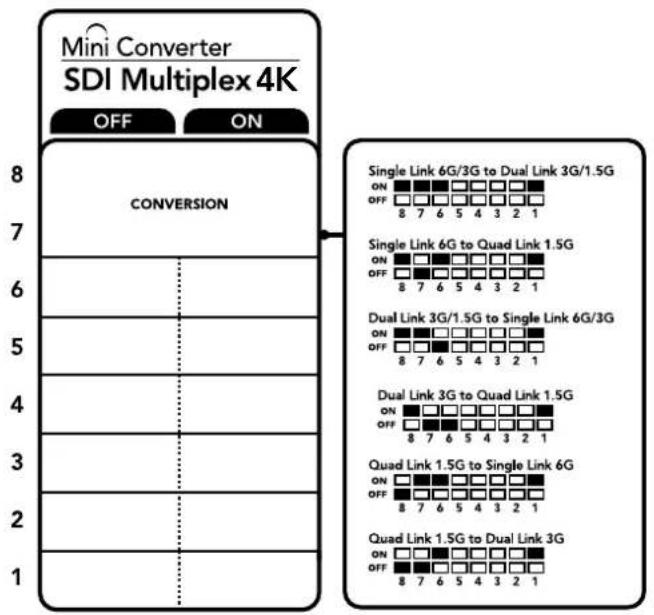
The switch legend on the base of your converter gives you all the information you need to change conversion settings.
Mini Switch Settings Example
Convert quad link Ultra HD to dual link Ultra HD by setting switch 8 to ON, and switch 7 to OFF.
SDI Connection Table
| Conversion Switch 8 Switch 7 Switch 6 Switch 1 Switch Diagram | ||||||||||
| Single Link 6G/3G-SDI to Dual Link 3G/1.5G-SDI | ON ON | ON ON | ||||||||
| Single Link 6G-SDI to Quad Link 1.5G-SDI | ON OFF | ON ON | ||||||||
| Dual Link 3G/1.5G-SDI to Single Link 6G/3G-SDI | ON ON | OFF ON | ||||||||
| Dual Link 3G-SDI to Quad Link 1.5G-SDI | ON OFF | OFF ON | ||||||||
| Quad Link 1.5G-SDI to Single Link 6G-SDI | OFF ON | ON ON | ||||||||
| Quad Link 1.5G-SDI to Dual Link 3G-SDI | OFF OFF | ON ON | ||||||||
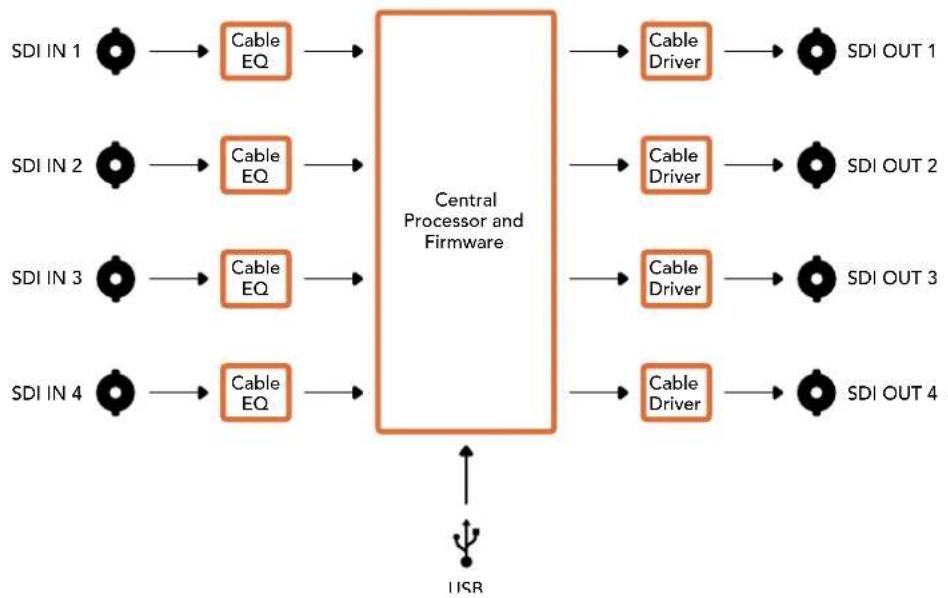
Mini Converter SDI Multiplex 4K Block Diagram
Mini Converter Sync Generator
Your Mini Converter Sync Generator includes 6 crystal stabilized video reference outputs for locking your video equipment to a common reference signal. Sync Generator produces high definition tri-sync or standard definition blackburst signals and is perfect for small studios and outside broadcasts.
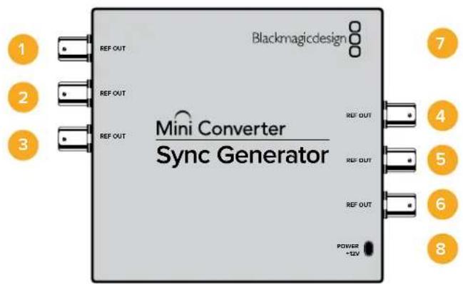
Connectors
1-6 REF Out
Reference video outputs BNC connectors.
7 Mini-B USB port
Connects to the Converters Setup software via your Mac OS X or Windows computer. The Mini Converter's internal software is also updated using the USB port.
8 Power+12V
12 volt power supply input.
Switches
Mini Converter Sync Generator's switches provide the following settings:
Switch 4,3,2 and 1-SYNC REF FORMAT BIT 3,2,1 and 0
Switches 4, 3, 2 and 1 are grouped together to select from many reference video formats, including:
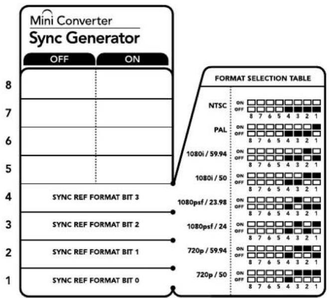
The switch legend on the base of your converter gives you all the information you need to change conversion settings.
Video Format Selection Table
| Video Format Switch 4 Switch 3 Switch 2 Switch 1 Switch Diagram | |||||||||
| NTSC OFF OFF OFF OFF | ON OFF 8 7 6 5 4 3 2 1 | ||||||||
| PAL OFF OFF OFF ON | ON OFF 8 7 6 5 4 3 2 1 | ||||||||
| 720p50 OFF ON ON ON | ON OFF 8 7 6 5 4 3 2 1 | ||||||||
| 720p59.94 OFF ON ON OFF | ON OFF 8 7 6 5 4 3 2 1 | ||||||||
| 720p60 ON ON ON ON OFF | ON OFF 8 7 6 5 4 3 2 1 | ||||||||
| 1080i50 OFF OFF ON ON | ON OFF 8 7 6 5 4 3 2 1 | ||||||||
| Video Format Switch 4 Switch 3 Switch 2 Switch 1 Switch Diagram | |||||
| 1080i59.94 OFF OFF ON OFF | ONOFF87654321 | ||||
| 1080i60 ON OFF OFF | ONOFF87654321 | ||||
| 1080PsF23.98 OFF ON OFF OFF | ONOFF87654321 | ||||
| 1080PsF24 OFF ON OFF ON | ONOFF87654321 | ||||
| 1080p23.98 ON ON OFF ON | ONOFF87654321 | ||||
| 1080p24 ON ON OFF OFF | ONOFF87654321 | ||||
| 1080p25 | ON OFF ON ON | ONOFF87654321 | |||
| 1080p29.97 | ON | OFF | ON | OFF | ONOFF87654321 |
| 1080p30 | ON | OFF | OFF | ON | ONOFF87654321 |
Mini Converter Sync Generator Block Diagram
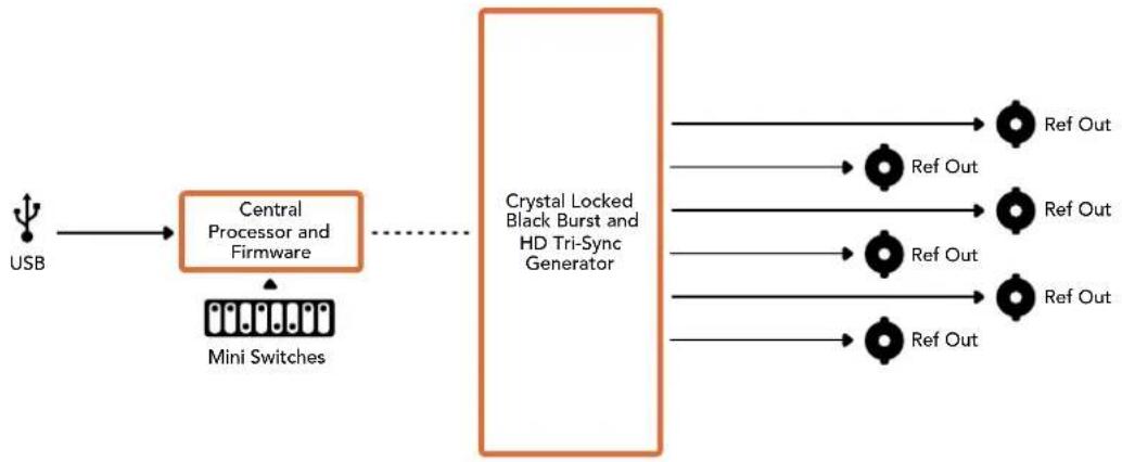
Mini ConverterUpDownCross
Your Mini Converter UpDownCross performs up, down and cross conversions as well as NTSC/PAL standards conversion and format conversion. Mini Converter UpDownCross can convert between video formats such as 720p to 1080i and PAL and NTSC video standards. It also provides up conversions with aspect ratios such as 4:3 Pillarbox and 16:9 zoom, and down conversion options such as letterbox 4:3 and anamorphic 16:9.
When conversion processing is set to OFF, the Mini Converter acts as an SDI distribution amplifier.
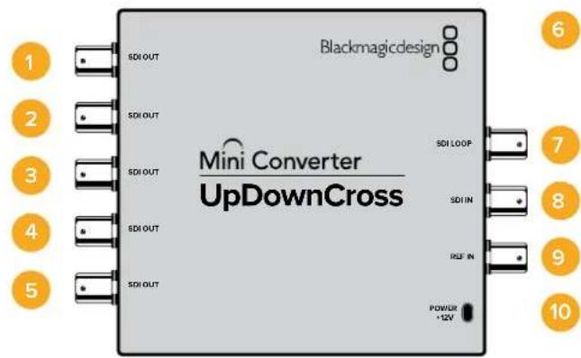
Connectors
1-5 SDI Out
SDI video outputs BNC connectors.
6 Mini-B USB port
Connects to the Converters Setup software via your Mac OS X or Windows computer. The Mini Converter's internal software is also updated using the USB port.
7 SDI LOOP
Direct output of your input video.
8 SDI IN
SDI Input.
9 REF IN
Reference video input.
10 Power +12V
12 volt power supply input.
Switches
Mini ConverterUpDownCross' switches provide the following settings:
Switch 8 - Aspect Ratio Conversion
Combinations of switches 8 and 7 set the video aspect ratio when up or down converting. For example, when down converting, the letterbox aspect ratio is applied by setting switch 8 and 7 to the OFF position.
Aspect Ratio Conversion Table
You've probably noticed switches 8 and 7 share settings for up and down conversions. This is because aspect ratio settings are determined by the output settings. For example, if you have switches 3 and 2 set for 1080i50 HD output, and processing switch 1 set to ON, Mini Converter UpDownCross will automatically set switches 8 and 7 for down conversion.
Below is a description for each aspect ratio conversion:
Up conversion
- 4:3 Pillarbox: This setting displays 4:3 standard definition inside a high definition 16:9 frame. Black bars feature on the sides.
- 14:9 Pillarbox: This setting is a compromise between 4:3 pillarbox and 16:9 zoom. The standard definition 4:3 image is slightly zoomed into, allowing more image in the 16:9 frame and reducing the amount of black bars on the sides, but slightly losing the top and bottom.
- 16:9 De-Squeeze: This setting de-squeezes the standard definition 4:3 anamorphic image until it completely fills the 16:9 frame. None of the 4:3 image is lost.
Down conversion
- Letterbox: This setting scales the entire 16:9 HD image into a 4:3 SD frame without squeezing, leaving black bars on the top and bottom.
- Anamorphic: This setting horizontally squeezes the 16:9 HD image into a 4:3 SD frame.
- Center Cut: This setting cuts a 4:3 SD frame from the 16:9 HD image. This aspect ratio setting discards a portion from each side of the 16:9 image.
Switch 1 - Processing Off - Processing On
When switch 1 is set to OFF all conversions are bypassed and the Mini Converter can be used to distribute your video to six SDI devices.
Mini Switch Settings Example:
Set the converter to up convert 4:3 625i50 video to 1080i50 with the 4:3 Pillarbox aspect ratio by setting switches 8 and 7 to the OFF position and switches 3, 2 and 1 to the ON position.
The switch legend on the base of your converter gives you all the information you need to change conversion settings.
Mini ConverterUpDownCross Conversion Table
| Input Video | NTSC Switches 1 and 2 ON | PAL Switch 1 ON | 720p Switches 1 and 3 ON | 1080 Switches 1, 2 and 3 ON |
| 525i59.94 525i59.94 625i50 720p59.94 | 625i50 720p59.94 | 1080i59.94 | ||
| 625i50 525i59.94 625i50 720p50 1080i50 | ||||
| 720p50 525i59.94 625i50 720p50 1080i50 | ||||
| 720p59.94 525i59.94 625i50 720p59.94 | 625i50 720p59.94 | 1080i59.94 | ||
| 720p60 525i59.94 625i50 720p60 1080i60 | ||||
| 1080PsF23.98 | 525i59.94 | 625i50 | 720p59.94 | 1080PsF23.98 |
| 1080p23.98 | 525i59.94 | 625i50 | 720p59.94 | 1080p23.98 |
| 1080PsF24 525i59.94 625i50 720p50 | 625i50 720p50 | 1080PsF24 | ||
| 1080p24 | 525i59.94 | 625i50 | 720p50 | 1080p24 |
| 1080p25 | 525i59.94 | 625i50 | 720p50 | 1080p25 |
| 1080p29.97 | 525i59.94 | 625i50 | 720p59.94 | 1080p29.97 |
| 1080p30 | 525i59.94 | 625i50 | 720p60 | 1080p30 |
| 1080i50 525i59.94 625i50 720p50 1080i50 | ||||
| 1080i59.94 | 525i59.94 | 625i50 | 720p59.94 | 1080i59.94 |
| 1080i60 525i59.94 625i50 720p60 1080i60 | ||||
| 1080p50 | 525i59.94 | 625i50 | 720p50 | 1080p50 |
| 1080p59.94 | 525i59.94 | 625i50 | 720p59.94 | 1080p59.94 |
| 1080p60 | 525i59.94 | 625i50 | 720p60 | 1080p60 |
| 2048x1556PsF23.98 | 525i59.94 | 625i50 | 2048x1556PsF23.98 | 2048x1556PsF23.98 |
| 2048x1556PsF24 | 525i59.94 | 625i50 | 2048x1556PsF24 | 2048x1556PsF24 |
| 2048x1556PsF25 | 525i59.94 | 625i50 | 2048x1556PsF25 | 2048x1556PsF25 |
Mini ConverterUpDownCross Block Diagram
Mini ConverterUpDownCross HD
Mini Converter UpDownCross HD is a powerful standards converter that gives you the ability to convert any SD or HD video format with up, down, or cross conversion via SDI and HDMI. This converter supports all SD and HD formats up to 1080p60 plus NTSC and PAL with aspect ratio options for up and down conversions. The HDMI input also accepts 1024 × 768 , 800 × 600 , and 640 × 480 computer output resolutions.
When conversion processing is set to OFF the HDMI and SDI outputs become loop outputs so you can feed the input signal to other HDMI and SDI equipment.
Connectors
1 SDIN
SDI input. The small LED next to the BNC connector illuminates when a locked SDI signal is detected. When both SDI and HDMI inputs are connected, the SDI input takes priority.
2 SDI LOOP
Direct loop output of your SDI input video.
3HDMLIN
HDMI type A video input. A small LED next to the HDMI IN connector illuminates to show when it detects a valid HDMI input.
4 REF IN
Reference video input. A small LED next to the REF IN connector indicates the reference lock status:
Constant white - the REF IN matches the format of the output video format set on the converter.
Flashing white - the REF IN is a valid video format but doesn't match the output video format set on the converter.
5 USB-C PORT
Connects to the Converters Setup software via your Mac OS X or Windows computer. The Mini Converter's internal software is also updated using the USB port.
6-7 SDI OUT
SDI video output BNC connectors.
8HDMIOUT
HDMI type A video output.
9 POWER +6 to 36V
6 to 36 volt power supply input. The support screw can be secured to the unit's power connector to prevent accidental disconnection. A small LED next to the DC input jack illuminates to show when power is connected.
Switches
Mini ConverterUpDownCross HD's switches provide the following settings :
Switch 1 - Processing Off - Processing On
When switch 1 is set to OFF all conversions are bypassed and the converter can be used to distribute your video via both SDI and HDMI outputs.
With switch 1 set to OFF the SDI and HDMI outputs match their corresponding inputs.
When switch 1 is set to ON, processing is enabled and switches 4 to 8 configure the converter's output.
Switch 2 - Level A and Level B 3G-SDI
When switch 2 is set to OFF the converter outputs level B 3G-SDI. When set to ON the converter outputs level A 3G-SDI. This provides compatibility with other SDI equipment that uses level A or level B 3G-SDI.
TIP If you have connected a 3G-SDI signal to 3G-SDI equipment and the signal is not being detected, try changing the setting for switch 2 as the equipment you're connected to may be using an alternate SDI level.
Switches 4-8
Switches 4 to 8 determine the format and standard of the converter's output signal. The switch configuration for each format and standard is shown on the table on the base of the unit.
Mini Switch Settings Example:
Video Format Selection Table
| Video Format | Switch8 | Switch7 | Switch6 | Switch5 | Switch4 | Switch Diagram |
| 525i59.94NTSC | OFF OFF OFF OFF | OFF | ONOFF87654321 | |||
| 625i50 PAL OFF OFF ON | ONOFF87654321 | |||||
| 720p50 OFF OFF ON OFF | ONOFF87654321 | |||||
| 720p59.94 OFF OFF ON ON | ONOFF87654321 | |||||
| 720p60 OFF OFF ON OFF ON | ONOFF87654321 | |||||
| 1080i50 OFF OFF ON OFF ON | ONOFF87654321 | |||||
| 1080i59.94 OFF ON ON OFF | ONOFF87654321 | |||||
| 1080i60 OFF ON ON ON | ONOFF87654321 | |||||
| 1080PsF23.98 OFF ON OFF | OFF OFF | ONOFF87654321 | ||||
| 1080PsF24 OFF ON OFF ON | ONOFF87654321 | |||||
| 1080PsF25 | OFF | ON | OFF | ON | OFF | ONOFF87654321 |
| 1080PsF29.97 | OFF | ON | OFF | ON | ON | ONOFF87654321 |
| 1080PsF30 | OFF ON ON OFF OFF | ONOFF87654321 | ||||
| 1080p23.98 | OFF | ON | ON | OFF | ON | ONOFF87654321 |
| 1080p24 | OFF | ON | ON | ON | OFF | ONOFF87654321 |
| 1080p25 | OFF ON ON ON ON | ONOFF87654321 | ||||
| 1080p29.97 | OFF | ON | ON | ON | OFF | ONOFF87654321 |
| 1080p30 | ON | OFF | OFF | OFF | ON | ONOFF87654321 |
| 1080p50 | ON | OFF | OFF | ON | OFF | ONOFF87654321 |
| 1080p59.94 ON | OFF OFF ON ON | ONOFF87654321 | ||||
| 1080p60 | ON | OFF | ON | OFF | OFF | ONOFF87654321 |
Converter Setup Utility
The Blackmagic Converters Setup utility can be used to change settings such as aspect ratio, and update your Mini Converter's software. All utility settings are maintained, even when the Mini Converter is switched off. You can access these settings by moving between the 'video,' 'audio,' and 'about' tabs.
The 'about' tab is detailed in the 'changing settings' section in this manual.
The 'video' tab for Mini Converter UpDownCross HD contains the following settings:

Use the 'video' tab in Converters Setup to select an SD aspect ratio.
Aspect Ratio for Standard Definition
Select an option for the aspect ratio of the SD output. You can choose 4:3 pillar boxed or 16:9. For example, if your input video is SD 4:3 then selecting 4:3 will output 4:3 pillar boxed to maintain the original 4:3 aspect ratio inside the 16:9 frame. However, if your input video is SD 16:9 select the 16:9 option to output a direct 16:9 conversion.
The default aspect ratio setting in the setup utility will output SD video as pillar boxed 4:3, however, you can set the converter to maintain a 16:9 ratio if required by selecting the 16:9 option on the 'video' tab of the setup utility.
Blackmagic Battery Converters
Battery Converter SDI to HDMI
With Battery Converter SDI to HDMI you can connect a huge range of HDMI displays and video projectors to SDI based equipment. Your Battery Converter SDI to HDMI automatically detects between SD/HD/3G-SDI and converts to HDMI with embedded audio. Battery Converter SDI to HDMI includes a built in rechargeable battery and recessed connectors protected by an aircraft grade aluminum chassis.
Connectors
1 Mini-B USB port
Connects to the Blackmagic Converters Setup software via your Mac OS X or Windows computer. The Mini Converter's internal software is also updated using the USB port.
2 SDI In
Primary SDI input BNC connector.
3 SDI Loop
Loop through output of your SDI input BNC connector.
4 HDMI
HDMI type A video output.
5 ON BATT OFF
Switches battery power On or Off. When set to On, the Battery Converter will keep working even if external power is lost. When set to Off, only external power is used to ensure built in battery power is saved. The LED near the switch indicates the battery charge level by a continuous illumination for 100 percent charge, three flashes for 50 to 90 percent charge, two flashes for 10 to 50 percent charge and a single flash if less than 10 percent charge is remaining.
6 Power +12V
12 volt power supply input.
Battery Converter SDI to HDMI Block Diagram
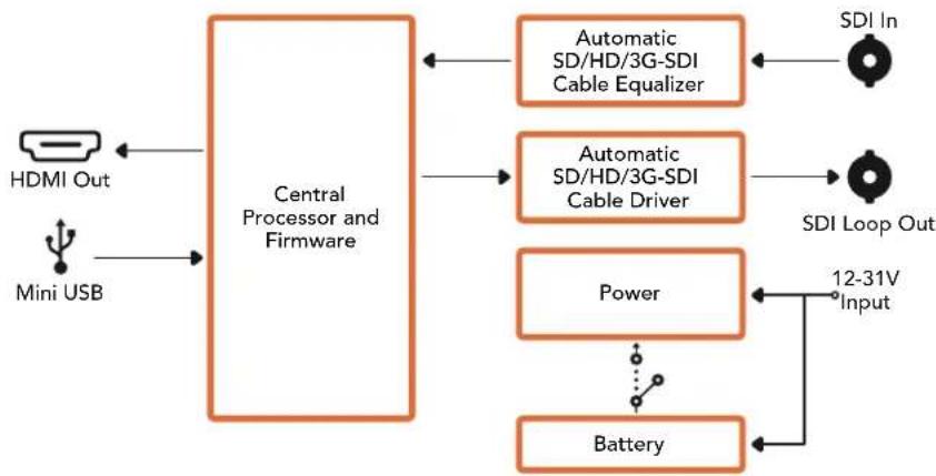
Battery Converter HDMI to SDI
Your Battery Converter HDMI to SDI can convert HDMI outputs from devices such as HDV cameras and game consoles to SDI. This means you can send video signals from HDMI over SDI using the longest SDI cables. You can even add SDI outputs to computers with HDMI compatibility. Battery Converter HDMI to SDI includes a built in rechargeable battery. Connectors are recessed and protected by an aircraft grade aluminum chassis.
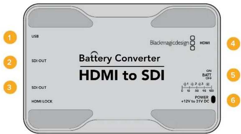
Connectors
1 Mini-B USB port
Connects to the Blackmagic Converters Setup software via your Mac OS X or Windows computer. The Mini Converter's internal software is also updated using the USB port.
2 SDI OUT
SDI video output BNC connector.
3 SDI OUT
Second SDI output.
4 HDMI
HDMI type A video input.
5 ON BATT OFF
Switches battery power On or Off. When set to On, the Battery Converter will keep working even if external power is lost. When set to Off, only external power is used to ensure built in battery power is saved. The LED near the switch indicates the battery charge level by a continuous illumination for 100 percent charge, three flashes for 50 to 90 percent charge, two flashes for 10 to 50 percent charge and a single flash if less than 10 percent charge is remaining.
6 Power +12V
12 volt power supply input.
Battery Converter HDMI to SDI Block Diagram
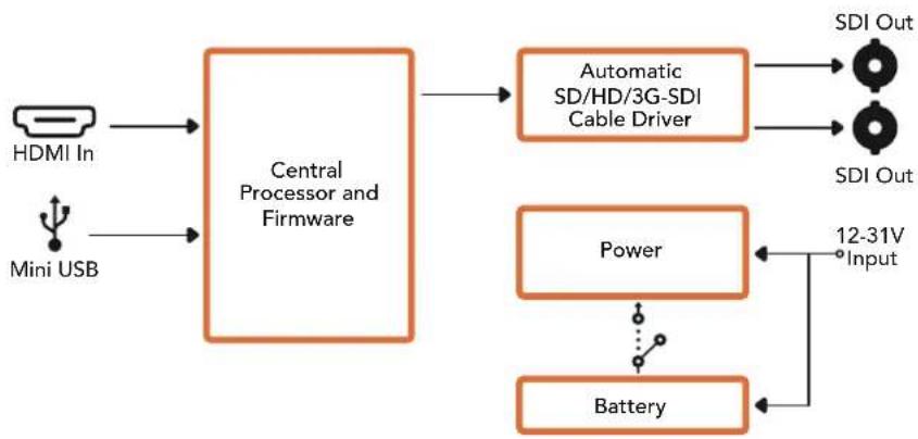
Help
Getting Help
The fastest way to obtain help is to go to the Blackmagic Design online support pages and check the latest support material available for your Blackmagic Converter.
Blackmagic Design Online Support Pages
The latest manual, software and support notes can be found at the Blackmagic Design support center at www.blackmagicdesign.com/support.
Blackmagic Design Forum
The Blackmagic Design forum on our website is a helpful resource you can visit for more information and creative ideas. This can also be a faster way of getting help as there may already be answers you can find from other experienced users and Blackmagic Design staff which will keep you moving forward. You can visit the forum at https://forum.blackmagicdesign.com
Contacting Blackmagic Design Support
If you can't find the help you need in our support material, or on the forum, please click the "Send us an email" button on the support page to email a support request. Alternatively, click on the "Find your local support team" button and call your nearest Blackmagic Design support office.
Checking the Software Version Currently Installed
To check which version of Converter Setup software is installed on your computer, open the About Blackmagic Converter Setup window.
- On Mac OS X, open Blackmagic Converter Setup from the Applications folder. Select About Blackmagic Converter Setup from the application menu to reveal the version number.
- On Windows, open Blackmagic Converter Setup from your Start menu. Click on the Help menu and select About Blackmagic Converter Setup to reveal the version number.
- On Windows 8, open Blackmagic Converter Setup from the Blackmagic Converter Setup tile on your Start page. Click on the Help menu and select About Blackmagic Converter Setup to reveal the version number.
How to Get the Latest Software Updates
After checking the version of Blackmagic Converters Setup software installed on your computer, please visit
the Blackmagic Design support center at www.blackmagicdesign.com/support to check for the latest updates. While it is usually a good idea to run the latest updates, it is wise to avoid updating any software if you are in the middle of an important project.
Warranty
Limited Warranty
Blackmagic Design warrants that Mini Converters and Mini Converters Heavy Duty will be free from defects in materials and workmanship for a period of 36 months from the date of purchase excluding connectors, cables, fiber optic modules, fuses and batteries which will be free from defects in materials and workmanship for a period of 12 months from the date of purchase. Blackmagic Design warrants that Battery Converters will be free from defects in materials and workmanship for a period of 12 months from the date of purchase. If a product proves to be defective during this warranty period, Blackmagic Design, at its option, either will repair the defective product without charge for parts and labor, or will provide a replacement in exchange for the defective product.
In order to obtain service under this warranty, you the Customer, must notify Blackmagic Design of the defect before the expiration of the warranty period and make suitable arrangements for the performance of service. The Customer shall be responsible for packaging and shipping the defective product to a designated service center nominated by Blackmagic Design, with shipping charges pre paid. Customer shall be responsible for paying all shipping charges, insurance, duties, taxes, and any other charges for products returned to us for any reason.
This warranty shall not apply to any defect, failure or damage caused by improper use or improper or inadequate maintenance and care. Blackmagic Design shall not be obligated to furnish service under this warranty: a) to repair damage resulting from attempts by personnel other than Blackmagic Design representatives to install, repair or service the product, b) to repair damage resulting from improper use or connection to incompatible equipment, c) to repair any damage or malfunction caused by the use of non Blackmagic Design parts or supplies, or d) to service a product that has been modified or integrated with other products when the effect of such a modification or integration increases the time or difficulty of servicing the product. THIS WARRANTY IS GIVEN BY BLACKMAGIC DESIGN IN LIEU OF ANY OTHER WARRANTYES, EXPRESS OR IMPLIED. BLACKMAGIC DESIGN AND ITS VENDORS DISCLAIM ANY IMPLIED WARRANTY OF MERCHANTABILITY OR FITNESS FOR A PARTICULAR PURPOSE. BLACKMAGIC DESIGN'S RESPONSIBILITY TO REPAIR OR REPLACE DEFECTIVE PRODUCTS IS THE WHOLE AND EXCLUSIVE REMEDY PROVIDED TO THE CUSTOMER FOR ANY INDIRECT, SPECIAL, INCIDENTAL OR CONSEQUENTIAL DAMAGES IRRESPECTIVE OF WHETHER BLACKMAGIC DESIGN OR THE VENDOR HAS ADVANCE NOTICE OF THE POSSIBILITY OF SUCH DAMAGES. BLACKMAGIC DESIGN IS NOT LIABLE FOR ANY ILLEGAL USE OF EQUIPMENT BY CUSTOMER. BLACKMAGIC IS NOT LIABLE FOR ANY DAMAGES RESULTING FROM USE OF THIS PRODUCT. USER OPERATES THIS PRODUCT AT OWN RISK.
Copyright 2018 Blackmagic Design. All rights reserved. 'Blackmagic Design', 'DeckLink', 'HDLink', 'Workgroup Videohub', 'Multibridge Pro', 'Multibridge Extreme', 'Intensity' and 'Leading the creative video revolution' are registered trademarks in the US and other countries. All other company and product names may be trade marks of their respective companies with which they are associated.

インズル/才レーニングマニアル
Blackmagic Converters
2018年6月
日本語

はこ
This is a Blackmagic One-tuple to be買ing求的做誠的如
Blackmagic Design CEO
glarnt-
目次
Blackmagic Converters
はしだに 95
電源の接続 95
比才の接続 96
才一德才の接統 97
管理の工法の 98
Blackmagic Converters Setup
1nst-198
内部SFTUFA的AFTF一T 99
Mini Converter SDI Distribution
4Kのアツフト一 100
設定の変更 101
スイチを使用て設定を変更 101
Blackmagic Converters Setup 芯
使用て設定を変更 102
About夕 103
Blackmagic Converter 103
Teranex Mini Converters 103
Blackmagic Micro Converters 104
Micro Converter SDI to HDMI 104
Micro Converter HDMI to SDI 105
Micro Converter BiDirectional SDI/HDMI 107
Blackmagic Mini Converters 109
Mini Converter SDI to HDMI 109
Mini Converter SDI to HDMI 4K 112
Mini Converter SDI to HDMI 6G 116
Mini Converter HDMI to SDI 121
Mini Converter HDMI to SDI 4K 124
Mini Converter HDMI to SDI 6G 127
Mini Converter SDI to Analog 130
Mini Converter SDI to Analog 4K 135
Mini Converter Analog to SDI 139
Mini Converter SDI to Audio 143
Mini Converter SDI to Audio 4K 146
Mini Converter Audio to SDI 149
Mini Converter Audio to SDI 4K 153
Mini Converter Optical Fiber 157
Mini Converter Optical Fiber 4K 158
Mini Converter Optical Fiber 12G 159
Mini Converter Quad SDI to HDMI 4K 160
Mini Converter SDI Distribution 161
Mini Converter SDI Distribution 4K 162
Mini Converter SDI Multiplex 4K 163
Mini Converter Sync Generator 166
Mini Converter UpDownCross 169
Mini Converter UpDownCross HD 173
Blackmagic Battery Converters 177
Battery Converter SDI to HDMI 177
Battery Converter HDMI to SDI 178
180
保证 181
はしだに
Backing port of the S-1000, 2.5V DC, 120V PWM voltage, 120Hz PWM frequency, 120Hz PWM frequency, 120Hz PWM frequency, 120Hz PWM frequency, 120Hz PWM frequency, 120Hz PWM frequency, 120Hz PWM frequency, 120Hz PWM frequency, 120Hz PWM frequency, 120Hz PWM frequency, 120Hz PWM frequency, 120Hz PWM frequency, 120Hz PWM frequency, 168MHz PWM frequency, 168MHz PWM frequency, 168MHz PWM frequency, 168MHz PWM frequency, 168MHz PWM frequency, 168MHz PWM frequency, 168MHz PWM frequency, 168MHz PWM frequency, 168MHz PWM frequency, 168MHz PWM frequency, 168MHz PWM frequency, 168MHz PWM frequency, 168MHz PWM frequency,
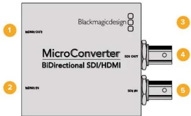
封装器
1 HDMI Out HDMI
TALI A BI DI O
2HDMI In HDMI
Tahll A bito oIleR.
3 昆虫克隆 USB/京东
注:USB-MAIOKLOR USB KIEIILBL 5V 10000000000000000000000000000000000000000000000000000000000000000000000000000000000000000000000000000
4 SDI OUT SDI
ViDIO 套(BNCK
5 SDINSDI
BNC
Blackmagic Converters Setup 小节
Blackmagic Converters Setup mytilerltoe thoe selctog beong hMicro Converter of
SopfTWeHrFenl 100000000000000000000000000000000000000000000000
AboutTabe观,相的自,
2 L-ANALOG or AES/EBU
S-1-Processing Off-Processing On
IiswuiiH

KnBnT 1
就的s用可上用范部一,
Swoihtelpreny
Blackmagic Mini Converter 1980 SDI Ondo 2000 1980
SDI ODOO
雀默莱[Bel(OutputLevels)备]
i 10000000000000000000000000000000000000000000000000000000000000000
![Blackmagic Design Micro Converter HDMI to SDI wPSU - 雀默莱[Bel(OutputLevels)备] - 1](/content/2026/03/454896/images/8f573bd63230fabf9285da352280dc9025c87922488ff6580feb080bb4789ac5.jpg)
Blackmagic Converters Setup [Audio]
藥樂
Mini Converter SDI to HDMI 落默 释
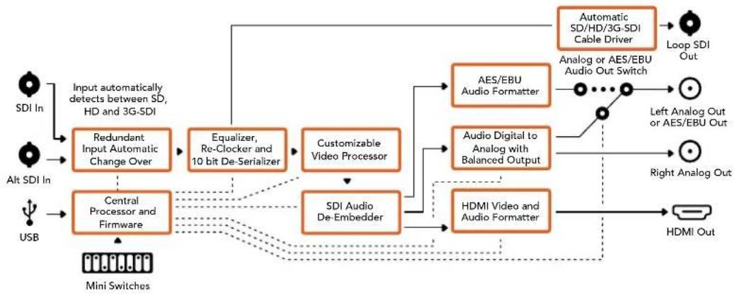
Mini Converter SDI to HDMI 4K
Mini Converter SDI to HDMI and SDI to HDMI 4K Heavy Duty mode will be used to accommodate HDMI. Mini Converter SDI to HDMI 4K is SD/HD/3G/6G-SDI which can achieve an end-to-end connection. HDMI Instant Lock function is used to ensure the secure and safe connection of the device. The HDMI amplifier is used to ensure the device's ability to operate in a wide range of conditions. Ultra HD has been designed to support different applications, including the use of ultralow current and high power.
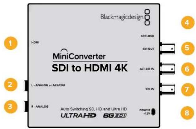
K
1HDMI
HDMI TAPAL A BUDI O CHUK
2 L-ANALOG or AES/EBU
私函相信的国造阿自托其云AES/EBU迪于AES/EBU
3 R-ANALOG
早凿朝南的国造阿半隆去O口O香
4 MLI -B USB 五
Swoi8oOFFro selrtoongloOnOIOONoR selrtoondIeAES/EBU OIO
4-SDI Audio De-Embed Bit 2
S戦き4の3,2は8がの主をON/OFF設定背心用到公合如。8の的相之在通SDI信默京中8の対部O口IO朝日主音HDM,阿自隆上且AES/EBU ODOLO 造梁歌 悦
S-3-SDI Audio De-Embed Bit 1
SwaI 4的藥男到中主哈
SloWt 2 -SDI Audio De-Embed Bit 0
SwaI 4的藥皂到中主
S-1- Processing Off - Processing On
IiswuiHn
HMI Instant Lock i 1 HMI Instant Lock i 1 HMI Instant Lock i 1 HMI Instant Lock i 1 HMI Instant Lock i 1 HMI Instant Lock i 1 HMI Instant Lock i 1 HMI Instant Lock i 1 HMI Instant Lock i 1 HMI Instant Lock i 1 HMI Instant Lock i 1 HMI Instant Lock i 1 HMI Instant Lock i 1 HMI Instant Lock i 1 HMI Instant Lock i 1 HMIInstant LOCK i 1 HMI Instant Lock i 1 HMI Instant Lock i 1 HMI Instant Lock i 1 HMI Instant Lock i 1 HMI Instant Lock i 1 HMI Instant Lock i 1 HMI Instant Lock i 1 HMI Instant Lock i 1 HMI Instant Lock i 1 HMI Instant Lock i 1 HMI Instant Lock i 1 HMI Instant Lock i 1 HMI Instant Lock i 1 HMI Instant Lock i
S-UI 8 - Analog Audio, AES/EBU Audio
Swoi8oOFFro selgehmangohn ondoOgONofoelgehanyDzEBU Odo
S-7-LUTOff,LUTOn
SWEI7ON/OFFLOFSELGTHELUTUHCHSYFOBNNBUBHCHSYHAP
6-LUT1,LUT2
Swoi16oFFro 50LUT1,ONOLOF 50LUT2
S-Wiki 5 - LUT On Loop Off, LUT On Loop On
S戦き5則OFFL締詠者LUTOnLoopOff,ONORL締詠者LUTOnLoopOn
Slo4-SDI Audio De-Embed Bit 2
StwI 4W3,28aJ9J60FF5F18A7HDM,ahnloH
S-Wiki 3-SDI Audio De-EmbedBit 1
SwaI 4的释明将中
SWDI 2 - SDI Audio De-Embed Bit 0
Swoi14的电男
S-1-HDMI Instant Lock Off,HDMI Instant Lock On
Swoi1HDMI Instant Lock Off,OFFro selgehman HDMl Instant Lock On
2 L-ANALOG or AES/EBU
相承的构法。
3 R-ANALOG
早
4 MI L -B USB 手
S-8- Analog Audio, AES/EBU Audio
Swoi 8o OFF ro selgeh aon go ono oan stckod ONo r selgeh nai tAES/EBU Odi oilr k i stcklnda Swoi 7oONo r selgeh ao i lkrue to sngd
S-7-HDMI Audio-Input Audio
S戦き7をOFF反成達者HDMI OukiO,ONOR成達者阿南LTOAES/EBU OukiO为
S-1 Processing Off - Processing On
2 L-ANALOG or AES/EBU
栽藻賊的國造阿藥羅去AES/EBU尼士日贝云口
3 R-ANALOG
早
4 MLI -B USB 五
Mini Converter Heavy Duty Mo-del's St-wi- is hong wu kbrro dwerlhyo
Mini Converter HDMI to SDI 4K的S戦きはと音和は上部の状態沈態を試証成功か
S-8-Analog Audio,AES/EBU Audio
Swoi 8o OFF ro selcthao gno oioo aenrto ONOro selcthao nAiTe AES/EBU OdiOnlreI 7on
S-7-HDMI Audio - Input Audio
Swoi 7o OFFro selcthre hmeBdiHDMIOOioo,ONoR selcthaonnnaLROgAES/EBU Ooi ooi sekchhal s
Slowi 2 and 1-Select Format Bit 1,0
Ultra HD的HD都由重做数合有在HDMI主系中用结合格,主系重做也中合如拉可重重成自上到下
dunh 1/da n kbrn 100000000000000000000000000000000000000000000000000000000000000000000000000000
S-1111111111111111111111111111111111111111111111111111
主合结尾是a#
AUTO - St-WiTc1是OFF, St-WiTc2是OFF.
Kunbertern is a sstic htrbereret ane hthd e n tht H d t
FORCE TO HD - Stwirr1 is OFF, Stwirr2 is ON.
Kunbrte ngre to hdeHD utn Ultra HD t chy h s HDMs sth eH D bio
FORCE TO ULTRA HD - St-Wi-12 ON, St-Wi-22 ON OFF.
KunberH
2 L-ANALOG or AES/EBU
私桑賊的公造阿南羅上O司AES/EBU尼贝罗
3 R-ANALOG
乌雀賊的公達阿日羅其云口
4 MLI -B USB 手
S-8- Analog Audio, AES/EBU Audio
Swoi 8oFFro selgeh a n oOuOg stckod ONou ro selgeh nn AES/ EBU OIOI ow lreik i sriokn da Swoi 7oONo r selgeh ao i lkrue to saugahs uoh
S-WiT7-HDMI Audio,Input Audio
Swoi7oFFro selgehreHDMIOOIO,ONrlo selgehreAahrogIAEES/EBU OoiOto sekchshou
S-3G Level B Output(Normal), 3G Level A Output
Mini Converter SDI to Analog
Blackmagic Mini Converter SDI to Analog是SD/HD-SDI到ahnalro夫KefoNtD与NTSC/PAL bitioo 香默或用反向音有如在贝阿AES/EBU及ahnalrogOoL 0010000000000000000000000000000000000000000000000000000000000000000000000000000000000
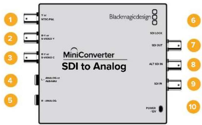
KuN
1 Y or NTSC/PAL
ahnelroKoFNTYtntKTNTSC/PAL
2 B-Y S-VIDEO Y
ahelroB KFOBNTB-Y,S-VideoY ChRe(BNCKnEeT).
3 R-Y果S-VIDEO C
4 L-ANALOG or AES/EBU
相的,如:AES/EBU 二日
5 R-ANALOG
乌雀朝南的国韵阿南归其云口云香/41
6 MLI-BUSBF
Mac OS X/Windows Blackmagic Converters Setup SóPiT Wefw Eae Ane Jellah Su
Jt. Mini Converter of the Naub SoPiT Wefw Eae USB FoT to Tbe
Ieaii Tchh Su Ie
7 SDI OUT
SDI bitioo BNC KnekeTe).
8 ALT SDI IN
RiTnDnTDSDIILKREIKBIL
9 SDI IN
孕 SDI
10 POWER +12V
12V 裁原 公国 信
sui
S-8-Analog Audio,AES/EBU Audio
Swoi 8 oFFo fio hou gnoon OIOOgONofo fio hao nAES/EBU OIOO
S7-7.5IRE-0.0IRE
7.5IRE 7.5Ie S-Video
S6 - SMPTE Levels - Betacam Levels
Swoi 6oFFr 5eF 5n SMPTE RBL,ONr 5eF 5n Betacam RBLu 5n 5n SmpTE RBLn Ht 5n 5n 5n Betacam SP DcK3eAeT oD SMPTE RBLu 5n 5n 5n 5n 5n 5n 5n 5n 5n 5n 5n 5n 5n 5n 5n 5n 5n 5n 5n 5n 5n 5n 5n 5n 5n 5n 5n 5n 5n 5n 5n 5n 5n 5n
S-Wiki 5 - Component, Composite 同 S-Video
S-WiJI 5L OFFLOFSTHnAALNOG KcFONNTBtDIOO OeRTOONoL FSTHnKcFOJITnS-Video
HD bitioomletoeS-VideoiFtT3oHnOON
4-SDI Audio De-Embed Bit 2
SwaH 4w3,28aJ9J60fON/OFFF 8J178A
3-SDI Audio De-Embed Bit 1
Sua 4
2-SDI Audio De-Embed Bit 0
Swicht4的释明将中止
S-1 Processing Off - Processing On
Ie MeNupEnrnnn daon KcnBtngn DndOoJouoJooJooJooJooJooJooJooJooJooJooJooJooJooJooJooJooJooJooJooJooJooJooJooJooJooJooJooJooJooJooJooJooJooJooJooJooJooJooJooJooJooJooJooJooJooJooJooJooJooJooJOO
4 L-ANALOG or AES/EBU
哉函函的园造阿落托其O迪云贝T AES/EBU 微信器O迪云
5 R-ANALOG
乌当期的国自阿日
6 MI N -B USB 扎三
Swoi8oOFFro 8oONoOfoAES/EBU
SUKI 7-7.5IRE -0.0IRE
7.5IRE 7.5IRE 7.5Ie S-Video
S-6 - SMPTE Levels - Betacam Levels
Swoi 6 oFF ro selgeh SMPTE ReB, ON onr selgeh anet Betacam RleB to sAing h ousnni. SMPTE RleB is hhi sAing h n Btacam SP dKeepo SMPTE RleB to sAing h ouhro, Betacam RleB sAing ybu to bndsi kih an h eBacam oro Swoi t selge to bengh sey
S-Wiki 5 - Component, Composite & S-Video
St-1] 3aJt OAnamorphic)
Mini Converter SDI to Analog 4K of Video] [Video] [Video]
函数调用代码如下:
Ie 13.
Mini Converter Analog to SDI
Mini Converter Analog to SDI Analog to SDI Heavy Duty BoDell to Thee Betacam SP DeKcAnd HDV KMaR, Keim Keh Cngn an Nalro Hg Jtioo fnd OIOO SD/HD-SDI BIOLO Rthch su hnu. Kfno TSD/HD& S-BiDIO o nne KpTn NTSC/PAL dH aonlto f nd t fo i 10000000000000000000000000000000000000000000000000000000000
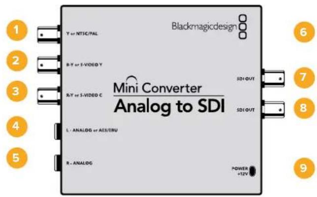
K
1 Y or NTSC/PAL
ahelroKoNTY 1B
2 B-Y S-VIDEO Y
ahelroB.
3 R-Y S-VIDEO C
ahelroR KFOHNT R-Y, S-Video C IeRbBNC
4 L-ANALOG or AES/EBU
S-1-Processing Off-Processing On
iswui
Swoihtelpreny
KemfonntoBviDiooAahneloGouDIOOIeRueWHeSwTcBandSwoTc5RoOffroSeHgBlackmagicMiniConvertersextqtoiIdofoBso
Blackmagic Converters Setup
<|im_start|>assistant
Export/Export
[About]
[About]
[About]
Mini Converter SDI to Audio
1 CH 1ANALOG or CH 1&2 AES/EBU
国達阿日羅其O口O 12AES/EBU DZIJIOT OIOO 14
2 CH 2 Analog or CH 3 & 4 AES/EBU
国達阿日羅上O口O 2EAS/EBU尼日尔O口O日O 3和4
3 CH 3 ANALOG or CH 5 & 6 AES/EBU
14
4 CH 4 ANALOG or CH 7 & 8 AES/EBU
14
5 ML -B USB 扎旦
S-5-Audio Group Bit 0
Swirki6的使命将告
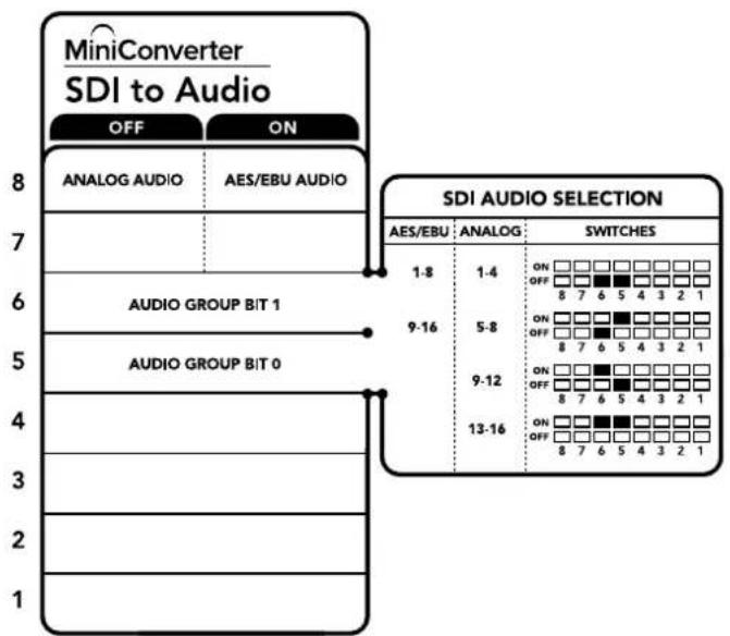
KnBtB TaBnFmEeHtNnSsWtT BReAeHrSn
整定越完,自要汉的多道
Swoi t
SwoiHro 86,50FFo 14
OukiO
1 CH 1ANALOG or CH 1&2 AES/EBU
国達阿日羅其O口O 1EES/EBU DZIJI0O OIOO 2
2 CH 2 Analog or CH 3 & 4 AES/EBU
4 CH 4 ANALOG or CH 7 & 8 AES/EBU
14
5 MLI -B USB 扎三
KnBtBbBnBnBnBnBnBnBnBnBnBnBnBnBnBnBnBnBnBnBnBnBnBnBnBnBnBnBnBnBnBnBnBnBnBnBnBnBnBnBnBnBnBnBnBnBnBnBnBnBnBnB
OukiO
[About]TablEJ#HJFJ#J#J#J#J#J#J#J#J#J#J#J#J#J#J#J#J#J#J#J#J#J#J#J#J#J#J#J#J#J#J#J#J#J#J#J#J#J#J#
Mini Converter SDI to Audio 4K of [Audio] Tabsetter n the duc and kng selctog uagulh s f
叠默默ReBb(OutputLevels)
oi Me n oioo hte iin to tclsh s hnu daa chnlo of oioo Re bokd ktof lro oolrnnl eon nn ene gai konu klnkhrh an the nlln hchne rnr hse hse uohni d.
00000000000000000000000000000000000000000000000000000000
Mini Converter Audio to SDI
S-7-Sample Rate Conversion, No Sample Rate Conversion
Swoi7oFFLOF50H 7OFFTOFFHOH 7oFFTOFFHOH
S戦戦7をOFF運締定期Hz上はAES/EBU 001000的産言歌功が広かのSDI 奎勅用48KHz産言歌功はIMBIDTRHNG。S戦戦7をON連成時通産言歌功は 壬効能は比効性現状が上は産言歌功は
S-Audio Group Bit1
Swoi 6和Swo15eNgJIOFFOJHJIOI 4A0EAEADJIOO 8AEBU ODDO 3D
S-Audio Group Bit 0
SwaH 6的
OoD0
Mini Converter Audio to SDI 落默 释
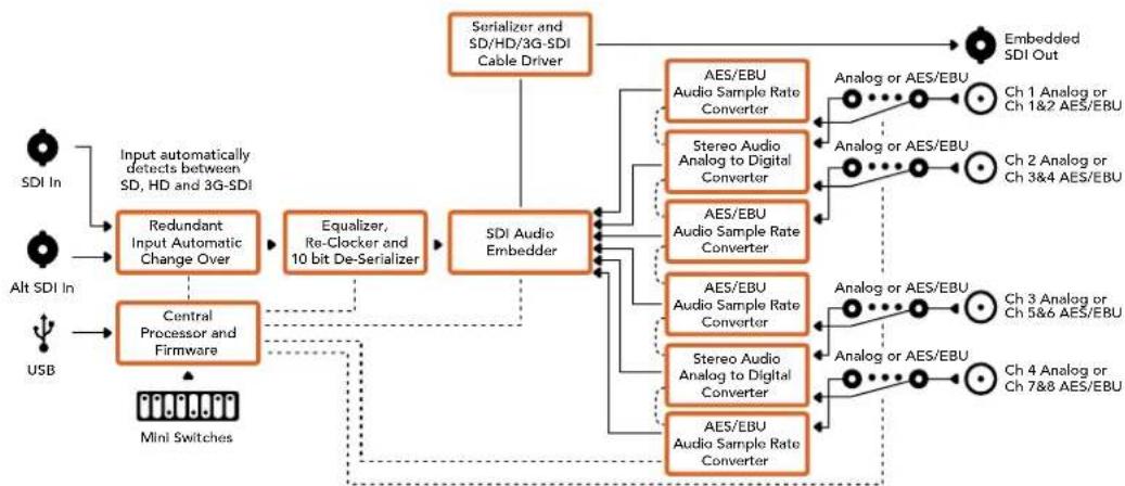
Mini Converter Audio to SDI 4K
S-7-Sample Rate Conversion, No Sample Rate Conversion
SWW7OFFLOF50H7H 70010000000000000000000000000000000000000000000000000000
Swoi7oFFro selgehao haofoeAES/EBUoioo的歌音歌动daiy
S-Audio Group Bit1
★相樂用樂勳樂樂樂樂樂樂樂樂樂樂樂樂樂樂樂樂樂樂樂樂樂樂樂樂樂樂樂樂樂樂樂樂樂樂樂樂樂樂樂樂樂樂樂樂樂樂樂樂樂樂樂樂樂樂樂樂樂樂樂樂樂樂樂樂樂
3 Optical In
S-1 Processing Off - Processing On
6V-36V 1E 1E 1E 1E 1E 1E 1E 1E 1E 1E 1E 1E 1E 1E 1E 1E 1E 1E 1E 1E 1E 1E 1E 1E 1E 1E 1E 1E 1E 1E 1E 1E 1E 1E
swo
Mini Converter UpDownCross HD的スイチは図音とをは成言の状態を試証成功か
Stw11-Processing Off-Processing On
Stwo110FFoF 100000000000000000000000000000000000000000000000000000000000000
SWEI10FFF
Battery Converter SDI to HDMI
Battery Converter SDI to HDMI将正常使用厂商版的HDMI MiniFloRei与BiDor ProToTto SDI相后当BnE 电能如。Battery Converter SDI to HDMI是SD/HD/3G-SDI到自动或到关机他HDMI反HDMIto B. Battery Converter SDI toHDMI是中置用包器拉内量而有从可调的高功机,
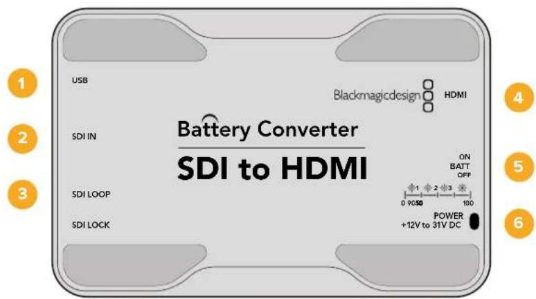
KuN
1.2-BUSB示例
Mac OS X/Windows 黑Magic Converters Setup 紅兆器用脚本安装 Mac OS X/Windows 黑Magic Converters Setup 索兆器用脚本安装 Mac OS X/Windows 黑Magic Converters Setup 索兆器用脚本安装 Mac OS X/Windows 黑Magic Converters Setup 索兆器用脚本安装 Mac OS X/Windows 黑Magic Converters Setup 索兆器用脚本安装 Mac OS X/Windows 黑Magic Converters Setup 索兆器用脚本安装 Mac OS X/Windows 黑Magic Converters Setup 素兆器用脚本安装 Mac OS X/Windows 黑Magic Converters Setup 素兆器用脚本安装 Mac OS X/Windows 黑Magic Converters Setup 素兆器用脚本安装 Mac OS X/Windows 黑Magic Converters Setup 素兆器用脚本安装 Mac OS X/Windows 黑Magic Converters Setup 素兆器用脚本安装 Mac OS X/Windows 黑Magic Converters Setup 細兆器用脚本安装 Mac OS X/Windows 黑Magic Converters Setup 素兆器用脚本安装 Mac OS X/Windows 黑Magic Converters Setup 素兆器用脚本安装 Mac OS X/Windows 黑Magic Converter
2 SDInJouSDIJILKRE(BNCKINKTE)
3 SDI Loop
SDI日制BNC封装电路的脱拉斯单击
4 HDMI
HDMI A B D O
5 ON BATT OFF
BateRl 10%
6 Power +12V
12V 裁元公国
Battery Converter SDI to HDMI 背景 送电
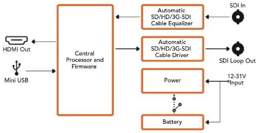
Battery Converter HDMI to SDI
Battery Converter HDMI to SDI 落默 释
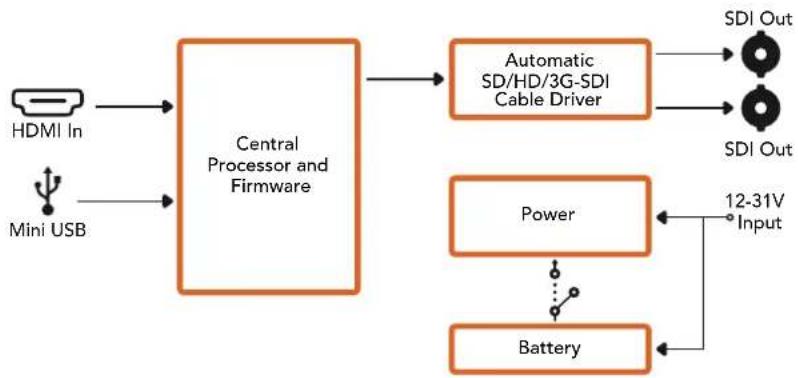
i
지원발기
Ja3eBnEeBnEeBnEeBnEeBnEeBnEeBnEeBnEeBnEeBnEeBnEeBnEeBnEeBnEeBnEeBnEeBnEeBnEeBnEeBnEeBnEeBnEeBnEeBnEeBnEeBn
Blackmagic Design for
Jr.
Blackmagic Design 1
Battery Converter SDI to HDMI 717
Battery Converter HDMI to SDI 718
Pomou 720
TapaHTna 721
Повтовka к paбote
Yto6bHaayabapotyckoHBeptepomBlackmagic,doctatoUHO NOKJIouHTbNITAHne,nCTOHHK BIneo KBOxOyUOBOpYDoBaHNeIINPnEmaCnHanaK BbIXOyU.
IopKIOUeHne nHTaHn
Iopknouhte npnilaraembl 6nok nntanna 12 B K ceteboi po3eke. Ecn konheptep imeet kaebnbHbXOMyT,ncnoNb3yte ero dny npedotBpaueHnra CnyaHoro oTooeHHHeHnKa6eJ.
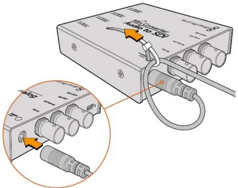
Ka6eHbHbXOMyT NOMOaTe npedotBpaTb CnyuauHoe OTKIOueHHe Ka6eH
Micro Converter
Moei nnneek Micro Converter ochaeneh npToM Micro USB. Bnaorapr 3omy nnoaunn HMOXHO NcnoB3oBaTb 3apnHbIe yctpoCTBa HeKOTOpbIX TepeOHOB nHACToNbHbIE KOMNIOTebpI c pa3bemom USB. Dnra 3TO rakke noonadet IIO6a dpyra TExnka, KOtopa nOepKBAET nepea TuKa hnpaeKeHem 5 B no nepexoHomy kaebio USB/Micro USB.
Battery Converter
Moei HneBki Bation Converter mEOT nepeKIOUATEb ON Batt Off, KOtOpB npedHa3HaeH dIy BbOpa cnoocoba nHTAHN. KOrda OH yCTaHOBJIeB bNOJoxHeNe ON, KOHBePtep 6ydt npoJokatb paobTaB daKe npn OTKIOUeHH NBEHrO nCTOHNa. EcII nepeKIOUATEb HaxoITcB b NOJoxEHN Off, IcNoJIb3yETcTobko BHeuHHe nITAHne. CBeToIOIDhINHnIKaTOp PdOM C nepeKIOUaTelem ropnt HeNPepbIBHO, KOrda bAtapera zapXeHa Ha 100%, MIRaET trn i Dba p3a npn 3apJe 50-90% n 10-50% COOTBeTCTBeHHO, a npn ypOBHe MeHee 10% zaropaetc n rachet.
IopKJIoueHne NCTOuHnKOB BnDeo
IopKIOUHTe ITOUYHK BINO KO BXOy KOHBepTea, a BbIXoCoeHNITc OobopyoBaHHeM, npedHa3HaueHHbIM dnn noJyEHHn CnHaJa.

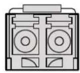
BNC HDMI Optical Fiber
B 3aBcMocTn OT moen BxOHa KOHepTepaX Blackmagic npedctabnre Tco6oB BNC-paBem, HDMI-nHTeppeuc nnn onTueckn nopT LC
OnTnueckn nHTeppeic
HekotopbkeonBepbblBlackmagicmeIOTcneuaabHoe rHe3do nla yctaHOBNOnTnueckoro SFP-moynnoCTaHapTy SMPTE c noidepKko 3G-,6G-nn12G-SDI.ETOT moynlpndctabJrEcoBo yctpoiCTBO npnema npepaun CnHaJa CnHTepfecom dna noKnIOueHn ONTOBOLOKOHHORO kaBJIa.
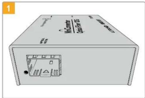
Ipeepncnonb3oBaHnem rHe3a Optical Out/In n3 Hero Heo6xOyMD ydaNtB nbIb.
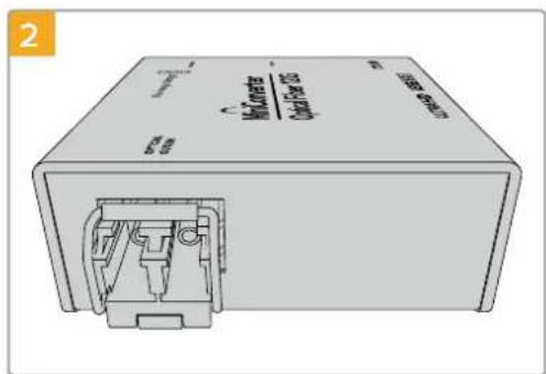
CHINMITEaunTHyKOpbIuKyNyCTaHOBNTe SFP-MOynbBrHe3do.
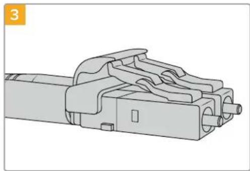
OToBOnoKoHHbI Ka6eIb Cha6KeH BepXHMnФHKcTOpamN DnA 3aunTb CoeHHeHn.
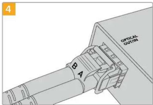
IopknIOHTe ONTOBONOKOHbIe Ka6enn.
Y6eNTcB TOM, YTO BXOHOH N BbIXoHOH
Ka6en IpaBnBHO NOKIOUeHb K Moynio, a
nxΦHKCaTOpbl 3aueNkHybl.
DononHnteBhie SDI-BXoDbI
HekotopbIe MoDen KOnBepTepeB Blackmagic ochauehI dononHnTeHBm SDI-BxOaMn dnyDblnpoBaHn. OHn IMeOT mapKIpOBky "Alt SDl In" nncnoJb3yIOr c np nponaadHn CnHaHa OCHOBHom SDI-BxoJe. Pp npepexoe Ha paobTy c dononHnTeHBm SDI-BxOaOM haunHaet Mrratb INdnKaTOp SDI LOCK.
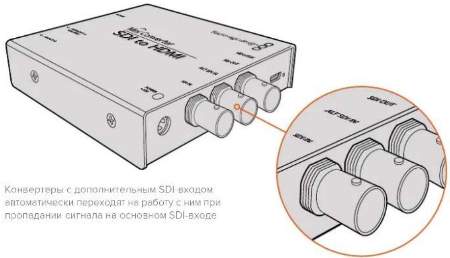
IopKJIoueHHe nCTOuHnKOB aydno
Aynopa3beMbI
HeKoTOpBie KOHBePtepbl Blackmagic mMeIOT pa3bEmbl dAmetpOM 1/4 IIOIma, uepe3 KOTopbIE MoJHO nOKnIOuATb BHeUHHe NCTouHnK bAaHCHOrO aHaIorOBOrO uINuΦpOBOr AOES/EBU-3Byka. 3To pa3bEmbl Tnna TRS c TpeM aKOHTAKTaM: T, R n S.
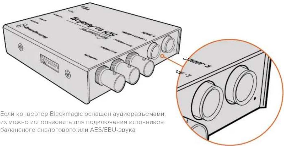
Ha pncyHke nHexe nokazha cxema pacnaikn 7tbpbeBoro pa3bema 1/4 noiMa. NcnoIb3y eE B KaueCTBe o6pa3u, MoXHO n3rOToBNTb CO6CTBEHNbI ayNOKa6enb.
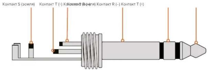
Ha cxeme pacnaiK (cm. npdeIbduyUcTpaHnu) noka3aHb noJoxnteHbH, oTPuTaTeHbHIn 3a3emraouk konTakbl. Ecn nnay aynooobopydOBAHn HyxHa opaTHa noJrpHOCTb, DOCTaTOH OmeHrMb MeCTaMn pacnaKy noJoxnteHbHO n oTPuTaTeHbHO KOHTAKOB.
PIMMEAHNE.BoBpempaobtbcAHAANOOBbIMcTepeo3ByKOM npnN3MeHIN NOJAPHOCTNOODHOpa3bemaHeo6xoDIMO npOeIaTbAHAONrHoeJeCTBNE DnB TOporo pa3bema.BIpOTNBHom cIyuea DBA CnHaHa He 6yUT COBnaATbNo pae.
YcTaHOBka npoRpaMMHoro o6ecneueHna
Ytuna Blackmagic Converters Setup
Ytnty Blackmagic Converters Setup nncnoIb3yIOT dny yctahOBKn HAcTpoE KOnBepTepa
n 06HOBHeHn BCTpoEHnO IIO. DcToynhble Oncm 3aBnCrt OT moeIn yCTpoiCTBa. HeKotopbie
KoHBepTebl Blackmagic He TpebyI NImeHnHaCTpoE IN He IMeOt BHyTpHeHero
nporpamMnHO oBeceHn, noTOMy y Hnx OTCyTCTByET IOpT USB. B 3om Cnyae MoxHo cpa3y
nepeuN K ONcaHncooTBetCTByUoeMmoJIHnke.

Ytnty Blackmagic Converters Setup moKHO yCTaHOBHT Ha KOMTbOtepbC onepaUNoHHHM CnCTeMaM Mac OS X u Windows
YcTaHObKa Ha Mac OS X
3arpynte ytnity Blackmagic Converters Setup c be6-caeta www.blackmagicdesign.com/ru.
2 Pacnakyte 3a rpyxehhbl qai n Bb6epnte COOTBeTCTBHyOu nn Dnck dna npocmoTa ercoepxHMOro.
3ДвждышкнTe KHONKOMMbIIN NO 3HaUKy yCTaHOBUNKa N cneDyIte INHCTpyKUIM Ha ekpaHe.
4 Nocne oKoHuaHn yTaHOBKn BbIepeNte Close. YTuNTa Blackmagic Converters Setup roToba K paBote.
YCTAHOBKa Ha Windows
1 3aŋpy3nte yɪnɪtɪy Blackmagic Converters Setup c Bæb-caiTa www.blackmagicdesign.com/ru.
2 Pacnakyte 3arpykeHHbI qaiI. YcTaHOBzIK yTINITBI I pyKOBOCTBO no 3KcnnyaTuaHaxoJrTcB nanke Blackmagic Converters Setup.
3Двжды ueJIKNHTe KHOHKOI MbluN NO 3HaUky yCTaHOBUNKa N cNeDuYTe INHCTpyKUm Ha ekpaHe.
4 BbBepTe Finish nIa3BepeHnY yCTaHOBKn.
Ytuna Blackmagic Converters Setup roToBA KncNoB3OaHIO.
OboBHeHnBCTpoeHHoro npoRpaMMHoro oBeCneueHn
Ecn konBepTep Blackmagic ochaueh nopTom USB, ero moxho nCnoJb3oBaT dny yctaHOBKn DOnonHnTeNbHbIX HacTpoek N O6HOBNeHn BCTpoeHHoro nporpaMMHOrO oecneueHn. IocneHnBcPnIO DocTyHa B ceHTpe noDdepKn Ha Be6-caIte Blackmagic Design no aDpecy www.blackmagicdesign.com/ru/support.
PnBbInonHeHnOsbHBeHnHaMoTeJxBlackmagic Micro Converter nntaHne noctynaet uepe3 npT USB, noTOMy DononHntelhBiE coeHNHeHn He TpebyOTc.
EcnBbncnbl3yeTBeaBlackmagc Mini Converter, Battery Converter nMini Converter Heavy Duty, nepe coeHHeHem c KOMlbotepom ueep 10s USB heo6xOIMo BkIouHTb nTahne yctpoictBa.
1 BkIIOUHTe KOHBeTpE.
2 CoeINHITe KOMNbTeP c KOHBePtePOM uepe3 nopT USB n 3aynrty Blackmagic Converters Setup.
HaHauaBHO CTpaHnue yTINNTbOyET OToobpaxaTcR Ha3BaHHe moen. PnnoKIOUeHN HecKnBkNX KOHBePTePOB BbEpeNe HyKhBI C NOMOsbI neBOI nII npaBOI cTePLKN.
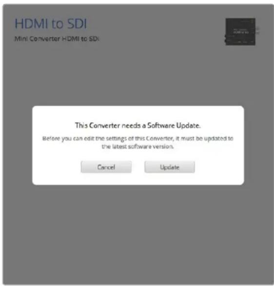
Ecnn KOHBePep mMeet 60one paHHIO BepcnIO BCTpoEHnOr nporpamMHoro oecneueHna, yTnHTa Blackmagic Converters Setup npednoKt BbInOnHnt bOHOBnHe
PnOTCBNNIOKNUeHHORO KOHBepTepa Ha NaaIbHyIO CTpaHcy BBBOIDTCs COo6eHne "No converters found".Ecn KOBBeTpepcoedHcKOMNBIOTepom uepe3 npT USB,HO He nolyaet NITAHNA,OTobpaKaETCAOooHHe "No power connected".ДЯdoCTyNA K HAcTPOIKAM HeoXoIMNOIOKJIQUHTB NCTOCHNK IITAHNA.
Ecnn konhepep Blackmagic nmeet oone paHHIO Bepcno BCTpoEHnro IIO, ytnnnta Blackmagic Converters Setup npednojnt nepenHa akTuJIbHyU. Yto6bl bIIOHnTb 06HOBneHne, cneynte INCTpyKuMaM Ha kpaHe.
06HOBJIeHne IO Ha Mini Converter SDI Distribution 4K
Mini Converter SDI Distribution 4K He Tpe6yet N3MeHeHnna napaTePoB, no3ToMy yctpoiCTBO HnyKHO NOkJIIOuATb K KOMNBIOTepy dIry UCTAOHOBKn HAcTPOEc C NOMOUBIO YTNNTb. TeM He MeHee, HA KOHBepTepe npEDyCMOTpe nOpT USB, uee3 KOtOpBIM MOxHO O6HO BHyTPeHHee IIO dIIN NOBbIeHncoBmectHMocTc DpyrIM o6OpyOBAHNem. TaK, BepCra 7.0.9 No3BOJraT yNyUHTb paBoTy c ciHaHAm 3G-SDI ypoBHnA.
HTo6bI nOlyuHTb DoCTyN K npTy USB Ha Mini Converter SDI Distribution 4K, BbInOnHnTe onncAHhle HIXe DeiCTBn.
PIMMEAHNE. Ppexde qem ChrB kpyk Kpnyca, oKIOHTe Mini Converter SDI Distribution 4K ot nTahn. Paobota doJxHa BbINHbTc KaBANPHPOBaHHbIM CneuaNCTOM C NcNoB3OBAHHe m AHTnCTaTnueCKOrO bpaCeta.
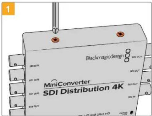
C NOMOsbIO OTBepTKn Phillips oTkpyTne yeTbIpe BnHTa M3 no 6okam Kopnyca Mini Converter SDI Distribution 4K.
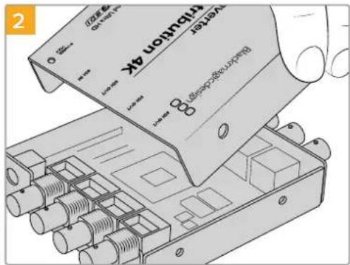
CHIMMITE KpbIUKy Kopnyca.
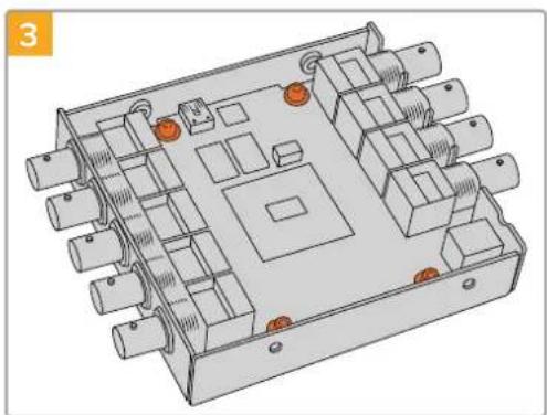
NcnoB3yorOBepkTyT10Tox,OTKpynteYtebpe BNHTa,KoTOpblkpenr nNaTy K Kopnyc Mini Converter SDI Distribution 4K.
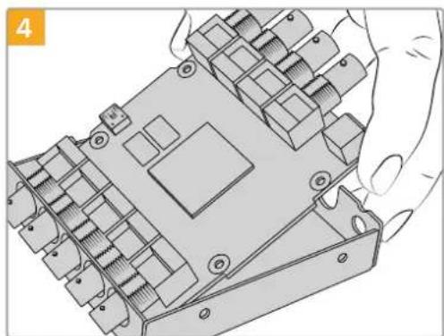
Octopoxho n3BneKte pNaTy, T06bl nOnyntb docynk npoty USB.
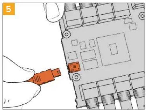
IoiKnIOuHnE Mini Converter SDI Distribution 4K K nCTOuHnky nHTaHn I coeDnHt e c KOMNbIoTePOM uepe3 npT USB. BblOnHnTe o6HOBHeHne BHyTppeHHero IO B O b6bUHOM nopAKe.

BbnonHnTe DeIcTBn, onucaHHbIe B waraX 1-4, B o6paTHOM npaKe.
PIMMEAHNE. Pn obaeHn c natoK konBepTepa Mini Converter SDI Distribution 4K depKeTte ee Toblko 3a Kpar, TObbl 36eXaTb KopoTKoro 3ambikaHn BHyTpEHNX KOMIOHEHTOB.
Изменения настpoек
EcnKoHBePep BlackmagicOnyckaet N3MeHeHHe HAcTpoek,ДЯnxYCTaHOBKnEcTBcNoCoba.MoxHoNcNoBzOBaTb BcTpoEHbIe nepeKIOUaTeHnHa KOpnyce nnporpaMMHyOytunuty Blackmagic Converters Setup.YtInuTa TaKke No3BOJnET paOToTb C npapMaTepAMn, KOtOpBie HeIb3a3aTb C NOMOsbIO nepeKIOUaTeHne,HanpIMep yPoBeHb aHaNoROBOrO BVdeOi ayDnOscuHaNoB.
I3meHHeHnHaCTpoek C nOMoUbIO nepeKlIOuTaTeJe
Mhore konBeprebl Blackmagic MeIOT BCTpoehbIe nepeKnIOuateiN.
YTo6bI N3MeHnTb HAcTpOuKy, YcTaHOBnTe nepeKKnOuateB B BepXHee IIN HIXKHee NOIOKeHne C NOMOUsBO ABTOpyuKn, HaNHyNE BOcMbN NepeKKnOuateNei No3BOJrEe T BblpaTb Heo6xOaMMyo KOMBuHaCnIO npaMeTPOB B COOTBeCTBUN C BblNoHNHeMm Ppeo6pa3OBaHnEM.
Ha HnKHe NIOBepXHOCTN KOpNyCa eCt bCxema CoeHHeH.N.HactpoKn NepeKluOaTeNe BbIOnHJOTCB COOTBeTCTBUN CNX HOMEPbIMN Oo03HaueHnMn (1-8) CneBa HAnpaBO.
IopnoBHee O nactpoiKax IpeeknOuateJe cm. pa3den c onncaHem COOTBeCTbkyoUeM oMeJI KOnBepTepa.B KaueCTBe NODcKa3Kn MOxHO INCNoB3OBaTb DnAarpAMMy Ha HIXHeN NOBepXHOCTN KopnyCa, Ondako OHa He Bcerda OTPaKaET KOM6nHaun DnE HeBaHb DoabLeHHbIX fYHKUIN.
PekomEndyetcnaobpaatabcnKnoceHneBepcnnypkoBOcTBa no kcnnyataun,KOtopaIocTynHa BpaZene npndepkKn Blackmagic Design Ha cTpaHnue www.blackmagicdesign.com/ru/support.
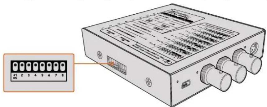
YcTaHOBkHaHCTpoek NpepkNIOuATEneN C nMOouA BTOpyKIN
XOTI yCTAHOBK 60JIbHINHCTBa HAcTPOE KnpEDyCMOTpeHb BCTPOEHbIe nepeKIOUaTeHN, HEKOToPbIE npaAMETpbI (HaNPmEp, yPoBEHb aHaIOrOBOr BnDeo- nIy AyDIOcIRHaIa) MOxHO I3MeHHTb TOnbKO C NOMOUsbIO pOrpamMHOH yTnITbl.
COBET. Mojenu Teranex Mini ochaeHbI INTepfeiom 12G-SDI n nopejkbaiot o6paotky cnHana b fopmatax do 4K DCI 60p. HfopmauO o paobte c 3TNMI KOHeptepamn o ob yctahOBke hactpoek c nomoubO ytnntbl Blackmagic Teranex Setup moxho haTn B pykoBoDCTBe no Teranex Mini Converter. PekomeHyetcra o6paatcbc K noCneHneB vepnnpykoBoDCTBa no ekcnnyataun, kOtopa dOCTynBa b paZdene npdeppkN Blackmagic Design Ha cTpaHnue www.blackmagicdesign.com/ru/support.
BklaJaKa About
BknaKa About ytnntb l Blackmagic Converters Setup nMeet oHaKOBn Bn dIe BCex moene. Ha He KOnBepTepy MoXHO npCBOITb IMy. IeKHTe KhoNko Mblu B none Name n BBeNTe HxKnH TeKT. HxMnTe Save, tO6b coXpaHtB.
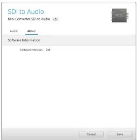
BklaJaKa About yinnnbl Blackmagic Converters Setup
N03BOJRAETPNCBOUTKOHBPCTEPYIMR.
3Dec6KeMOXHOIPOBepNTB BepCNIOYTNNTbl.
Ctpoka Software Information Ha BknaKe About copeKHT Homep Bepcn IIO, nnoIb3ayemoi KOHbepTePOM Blackmagic. EcnBCTpoEHHO nporpaMMHoe oecneueHne Tpe6yET 0bHOJIeHNA, 6yET OTo6paKaTbCA KONIka, C NOMOuBIO KOTopoM MOXHO yCTaHOBNT b AkyaIbHyIO BEPCNIO.
Mодели конвертуов Blackmagic
KoHBeptepb Blaekmigc - 3to noHbHn Habop peeHn dIy npeoobpaObaHn CnHaHa CaMbix pa3hix npoeKtax. TaK, moJIeMini Converter otNuaAOTcMaIbIM BecOM, tTO no3BOJET yCTAHOBHTB IN B CTOnKy IIN HA dpyroE o6OpdyOBaHne. JInHeKa Battery Converter npedHa3HaueHa dIra kCnpyatauB MObNbHbIX ycNoBnx npi OTCyTCTBn 3HeprochAo6KeHn, a Micro Converter SDl to HDMI n HDMI to SDl moryt nonyatb nItaHne uepe3 nopT USB npn NOkKnUoyEHn K MoHITOpam n HactOnlbHbIM Komblotepam.
Hnke coepkntc onucaHne konBepTepoB Blackmagic, npaKa paObTb c nepeKIOUaTeIaMn u yctahOBKn HactpoeK c nOMoUbNo nporpaMMHOyTuNTbI.
KoHBeptepbl Teranex Mini
Moei Teranex Mini ochaueHb Hntepfcom 12G-SDI n noDpeKnBAOT obpaobKy ciHa naB B opMaTao 4K DCI 60p.3TN KOHBepBdoNcyAOT yCTaHOky DoonHtBelho KOHTPOBHO nanei Teranex Mini Smart Panel, kotopaa meeT K-dncnn,Knokn nOBOPoTHyO pyk.Bolee noDpoBHyIOHOpMaUIO, B TOM uCne O b ynpABLeHH C nmoouy tINbl Blackmagic Teranex Setup, moXHO hainB pykoBOdCTBe no EKnpyatauHN Teranex Mini. Dnaero 3arpy3kn nepeinTe B pa3deI noDepxKn Ha Be6-caite Blackmagic Design no apecy www.blackmagicdesign.com/ru/support.
Blackmagic Micro Converter
Micro Converter SDI to HDMI
3TOT MIKPOKOHBePc CnyxNITIIN BbIBOa I3o6paKeHnC SD-OBOpyIOBaHnHa DnCnnei INBundeONpoEKTopb c HDMl-INTeppeom. Modenb Micro Converter SD to HDMI aBtOMaTIueckn BbIbnpaET SD, HD nII 3G-SDI n BblOnJHReI pneo6pa3oBaHnE cnHana co BCTpAnBaHnEM 3Byka. PpOchHyk Kopnyc n3 aIIOmHNr OTnIuaeTcBCEPXKOMNaKTbIMn pa3Mepamn, a NITAHne NOCTynaet Chepe3 npT USB. 3TO IO3BOJAE TcNOJIb3OBAbB KauchETBe UCTOCHNA 3Heprnn HAcToJIbHbIE KOMbIoTEpbI n TeJeBn3OpbI.Длп NOdKnIOUeHnY yctpoiCTBa NODoiTe O6bHbI Ka6eNB USB/ Micro USB, c nomoubIO KOtporo 3apjXaOT MObIJbHbIte TenefoHbI. Tako Ka6eNB MoXHO npno6pcTeB bOBJshINCTBe MaRa3INOB b6ItOB0I 3NeKTPoHNIK.
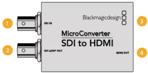
Pa3beMbl
1 SDI IN
OCHOBHON SDI-BXoD C BNC-pa3beMOM.
2 SDI LOOP
CKB03HOn SDI-BbIXoD c BNC-pa3beMOM.
3 NopT Micro USB/nntaHne
ObecneuBaET nTaHHe c nOmoBIO npnnaeMoro 6noka nn yctpoNCTBa, noepKnBaIoero nepeauy toka HappKeHem 5 B no Kaebio USB/Micro USB (TB nnPiK). TaKke cnKyNT dIy nOdkIoueHn K KomblTepy c onepaunHOH couTeMoI Mac OS X nn Windows n ynpabNeHn c nOmoBIO ytnnbl Blackmagic Converters Setup.
4 HDMI OUT
HDMI-BbIXoTnA.
Hac troponu ytnntbI Blackmagic Converters Setup
Ytuna Blackmagic Converters Setup no3B0nAeT MeHb HAcToPkn MKNpOKoHBeptepa nOboHbIb ero nporpaMMHoe oecneueHHe. DnA DocTyna K 3TNM HAcToPknAM NcNoIb3yIOT BkJaKn Video n About.
Pa6oTa C BklaaKo Aobut onncana B pa3dene IImeHHe Hactpoek DaHHoro pykoBocTba.
BklaKa Video nla Micro Converter SDI to HDMI daet BO3MOxHocTb BbipaTb onicaHHble Hnke onu.
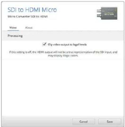
Onuia "Clip video output to legal levels" nCnoIbayetcno ymoIaHIO. OHa oBecneuBaET KoppeKTHbI BbIBoD BXOJaeroSDI-cnHana uepe3 HDMI-nHTepfieC.
MeHIO Processing
Onuia "Clip video output to legal levels" no3B0n8eAaantnpoBaT BxOJaun SDI-cunHan dna BBIOda uepeHDMI-ntepfeic. No ymoJauHH OHa oJnxHa 6bY BkIoueHa.
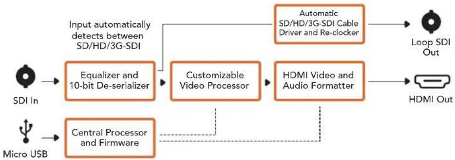
Cxema coeHneH Micro Converter SDI to HDMI
Micro Converter HDMI to SDI
Modenb Micro Converter HDI to SDI cnxntn BbVbOda cHMD-ycpocTB (taknx kak HDV-kamepbui nrgpobie koncoi) H aTexnky c SDI-nhtepfecom. bnaorapra 3omy moxno nepedabatn06paexene n3 HDMI-nctouhka no SDI-kabeio ha 6oNbwoe pacctoHne, a taKxe ioknquatb kombotep K SDI-obopyoabaio. Ipouhyk Kopnyc n3 anOMHH oTInhaetc CBepxkomnakthbmi pa3mepam, a ntaHne noctynaet uee3 nopT USB. 3to no3Bolare INCIOB3OBaB t KaeeCTBe NCTOUHnKa 3Heprnn HactoNBhle KOMNBoTepebl TeJeBn3Opbl. IIN naOKnlueyuCTpoictBa nOoiDeT obuHb Kaebb USB/Micro USB, c nomoubo KOtoporo 3apjaoT MOBnblte TnefoHb. TaKo Kaebb MoXHO npnoobpctn B 6oNbunHCTBe Mara3nHOB 6bTOBOJ 3neKTPOHNI.
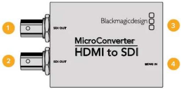
Pa3beMbl
1 SDI OUT
SDI-BbIXoD c BNC-pa3beMOM.
2 SDI OUT
Btpoi SDI-BbIXoD.
3 Nopt Micro USB/nntaHne
ObecneuBaetnTaHHe c nOmoBIO npnlaeMOro 6noka nn yctpoiCTBa, noepKnaBauoero nepeauy ToKa HapJxKeHem 5 B no KaebIO USB/Micro USB (TB nnPi).Takke cnjxNIT dIy nOdkIoUeHn K Komblotepy C onepaOnHOHc nCtEmoM Mac OS X nn Windows uynpabEnHn KOHbEpTePOM nn OboHbEnHra erO bctpoeHHoro PO c nOmoBIO ytnntBi Blackmagic Converters Setup.
4HDMI IN
HDMI-BXOД Tuna A.
Hac troponu ytnntbI Blackmagic Converters Setup
Ytuna Blackmagic Converters Setup noaBolniet MeHb HacpoKN MKNpOKOBepepa nOHOBnIb ero nporpaMMHoe oecneueHne. Dna DocTyNA K 3TNM HAcToKAM NcNoJIb3yIOB BkJaKn Video n About.
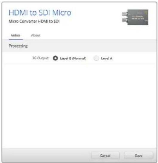
Bkana Video ytnnbl Blackmagic Converters
Selup no3BONHETyCTAHOBHTyPOBEHBSDI-cnHana
Pabota C Bklaikoi About onica H pa3dene IImeHne Hacpoek DaHHoro pykoBodCTBa.
BklaKa Video dnia Micro Converter HDMI to SDI daet Bo3MOXHOCTb Bb6paTb ONCAHbte Hnke onuim.
MeHoo Processing
MeHIO 3G Output daet BO3MOXHocb HcnoIb3ObaT bOnuio "Level A" nn "Level B". 3Ta Hactpoika no3B0JAEr BbIpaTb cNoCob BbIBoDa cnHana 3G-SDI Ha o6OpyDObaHne, KOTOpoe nOndepxNBAe ToIbKO oINH yPoBeH - Level A nn Level B. No yMonuaHIO nCnoIb3yETcOnuia "Level B".
Cxema coeHneHn Micro Converter HDMI to SDI
Micro Converter BiDirectional SDI/HDMI
MoJIb Micro Converter BiDirectional SDI/HDMI no3BONaET OJHOBpeMeHNO BbBOAnTb SD- nHn HD-cunHaC HDMl-yCTpOINCTBa HA TexHnky C SDI-HHTepFeuCOM HAObOpOT BmecTe Co BCtpanBaHnem 3Byka. 3TO o6eCneuBaET nepeDauy N3OpaXeHnN 3 HDMI-nCTouHKnOB (HanpImep, HDV-Kamep) no SDI-KaBeJIO Ha 60nbUoe pacctOHaHe, a TAKKe pneOpa3oBaHne 6oPaTHoro SDI-noToKa npi NoKInoueHHn TexHnKn K HDMl-ObOpyDobAHnIO (HanpImep, TeLeBnOpy c HDMl-HHTepFeuCOM).
PnncnoB3OBaHnToIbko Ondoro BxOda SDI-N HDMI-BbxOdbCTaHOBATcCKBO3bIMN,TO nO3BOJnTnepeBaTaNoctynaoiunCnHnHaDpyroEHDMI-nnSDI-6OpdyoBaHn.
Model Micro Converter BiDirectional SDI/HDMI abTomatueckn onpeidenet fopmat Ha Bxode (SD/HD/3G-SDI) n cnojbyet ero Ha bixoje.
IpouHb KOpNc n3 aIOMHHa OTnuaeTc CBepxKoMnakTHbIM pa3MepaAM, a NITaHne NoCTynae Tpe3 npT USB. 3to no3BOJHET mnoJIb3ObaT b KaueCTBe nCTOHyKa 3Heprn HAcToIbHbIe KOMNbItepbI n TeBn3Opbl. Ira n oNDKIIOUeHn yCtpoCTBa nOdoJeT oBlyHbIKabE h USB/ Micro USB, c nOMoUbIO KOtOporo 3apjXaOT MObInbHbIE TenePOnbl. TaKoI KabEn MoXHO npNoObpctn B 60lbWnHCTBe MaRa3INHO BbTOBoI 3NeKtpOHKn.
Pa3beMbl
1HDMI OUT
HDMI-BbIXOaTnA.
2 HDMI IN
HDMI-BXoD TunaA.
3 Nopt Micro USB/nntaHne
ObecneuBaet nTahne c nOmoBko IIOBoro yCtpoiCTBa, noDepKBAUoero nepeauy ToKa HanpJxKeHem 5 B no KaBeIIO USB/Micro USB (TB nnPiK). TaKxe cnYknt dny PoKnIOUeHn K KombIoTepy c onepauOnHOHcnCTeMoM Mac OS X nn Windows n npabEnHc n oMOsBu yTmTTb BlaKmagic Converters Setup.
4SDIOUT
SDI-BbIXoC BNC-pa3beMOM.
5 SDIN
SDI-BXoC BNC-pa3bemOM.
Hacrtpoynytnntbl Blackmagic Converters Setup
Ytnta Blackmagic Converters Setup no3BnAeMeHb HAcTpoKn MmKpOKOBepTepa nO6HOBnIbEero nporpamMHOe oecneHHe. Ira doctya KnapaMetpam NcNoJIb3yIOT BkJaDKn Video n About.
Pa6oTa C BknaIkoB About onncaHa B pa3dene «IImeHHeH He HactpoEK>.
BknaKa Video nIra Micro Converter BiDirectional SDI/HDMI daet BO3MOXHocTb Bb6paTb ONcaHHbIe Hnke onn.
Onuia "Clip video output to legal levels" nnonbayetcno ymonnauHIO. OHa oecneueBaet KoppeKTHbBbBOD BXoAeero SDI-cunhana uepea HDMI-ntepfeic.
MeHIO Processing
Onuia "Clip video output to legal levels" no3Bolnaret aandtnipoBaTB BxOJaSNI SDI-cnrHAn dny BBboda uepe3 HMI-ntepfeic. No ymouhno OHa donjha 6bItb BKIOueHa.
Hactpoika 3G Output daet BOZMOxHocTB nCnOJIb3OBaTb onuio "Level A" uN "Level B". OHa onpeDeneT cnOCoB BBIOda dIra CnHana 3G-SDI, yTO6bl oEeNeHTb COBMecTMOCt b cObOpyDobAHnEM, KOtOpoe noJdEpxKIBaET BBOI 3G-SDI toIbKO kAk Level A uNl Nlevel B. ITo yMOnUHAnIO nCnOJIb3EyTec onuia "Level B".
Cxema coeHneHn Micro Converter BiDirectional SDI/HDMI
Blackmagic Mini Converter
Mini Converter SDI to HDMI
TOT MINH-KOHBepTeP No3BOJAE TpepaTa H3O6paKeHne c SDI-OBOpyDobAHnHa DnCnien n BIndeonpoeKTopb c HDMI-HnTepefcom. Moenb Mini Converter SDl to HDMI aBTOMaTHueckn Bb6paeT SD, HD nIN 3G-SDI n BbIOJIHeT ppeo6pa30BaHne cnHana co BCtpanBaHem 3Byka n er O bIBoDM o Ha balaHcHb anAHOroBb nN AES/EBU-BixoJd.
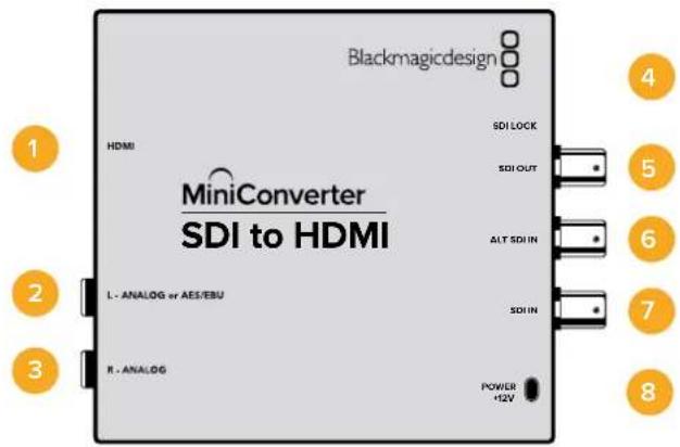
Pa3beMbl
1HDMI
HDMI-BbixoTunaA.
2 L-ANALOG nnn AES/EBU
Baanchbna ananorobn (neBkana) nnnu npoBoA EAS/EBU-aynoBixOc pa3bemom 1/4 duim.
3 R-ANALOG
BaanhChn b aHaONOBb yauNOBbIXoN (npabBk KaH) Cpa3bEmOM 1/4IouMa.
4 NopT MINI-B USB
ObecneuBaet noKnHoueHn K Komblotepy c onepauonHOn ciCTemOa Mac OS X nN Windows dIpaBt cyntinToB Blackmagic Converters Setup. TaKke cnYknt dnna 6bHOHeHH BcTpoEHHoro PO MmHi-KOHBeptepa.
5 SDI OUT
SDI-BbixoC BNC-pa3beMOM.
ALT SDI IN
DOnonHnTeIbHbN SDI-BxOd nIyDy6nIpOBaHn ciHaHa.
7 SDIN
OCHOBHOI SDI-BXoI.
8 POWER +12V
Bxod nitaHn12B.
Ipeeknouatei
IpeeknouateB 8 - Analog Audio, AES/EBU Audio
YcTaHOBtne nepeKIOUaTeIb 8 b noJooKeHHe OFF (BbIKn.)yTObblBbOuNTb banaHCbH aHaIorOBbI 3Byk, nI ON (BKn.) dIra nCIOJIb3OBAHnA uNΦpOBOr AOES/EBU-BbXoJa.
IpeeknouateB 4 - SDl Audio De-Embed Bit 2
Ipeeknioatei 4,3 n 2 no3oJnoIOT nCnoJIb3ObaT BOCEm kOMBnaU ON/OFF.Cnx nmoou Bo MoXHO bIbpaT BOCEm pa3bIX nap ayDIOKAHANOB,KOTOpBE 6yUT BvIDeNEHb IN3 BXOJUero SDI-cnHaHa Ira BbBOda Ha HDMI-INTepfeic,aHAnorOBb nnu CnpobOy AES/EBU-pa3bEmbl.
IpeeklouateB 3 - SDI Audio De-Embed Bit 1
CM. onncaHne nepeKlnouateT4.
Ipeeknouateb 2 - SDl Audio De-Embed Bit O
CM. onncaHne nepeKniouateTn4.
Ipeeknouateb1 - Processing Off/Processing On
TOT nepekniouateIb He nCnonb3yETc.
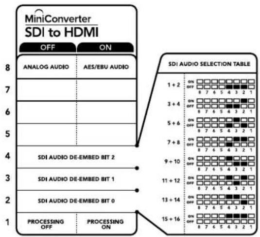
CxemaHaHnKHeNOBepxHOCTN KOpnyCa cOePxyT ONcAHne HAcTPOeK, COOTBetCTBYUUX pa3HbIM NOnOKeHNrM NepeKIOuATEnei
Ppimep Hactpoek nepeeknouatele
Ecn n3 SDI-noToKa HyxHO BbIeNtB ayDnOKaHaNb1 1 n 2 dnn Xx BBIOda Ha aHaIorOBb BbIXoJ, yctaHOBnte nepeKIOUcATE8,4,3 n 2 B noLoXeHne OFF (BbIK).
AydnookaHaJIbSI-DcHana
| Аudносаныпескюстов 4 пескюстов 3 пескюстов 2 | Посьени пескюстуя | |
| 1 и 2 OFF OFF | ON OFF 8 7 6 5 4 3 2 1 | |
| 3 и 4 OFF ON | ON OFF 8 7 6 5 4 3 2 1 | |
| 5 и 6 OFF ON OFF | ON OFF 8 7 6 5 4 3 2 1 | |
| 7 и 8 OFF ON ON | ON OFF 8 7 6 5 4 3 2 1 | |
| 9 и 10 ON OFF OFF | ON OFF 8 7 6 5 4 3 2 1 | |
| 11 и 12 ON OFF ON | ON OFF 8 7 6 5 4 3 2 1 | |
| 13 и 14 ON ON OFF | ON OFF 8 7 6 5 4 3 2 1 | |
| 15 и 16 ON ON ON | ON OFF 8 7 6 5 4 3 2 1 | |
HacrtpoiKn yTnntbI Blackmagic Converters Setup
Ytuna Blackmagic Converters Setup no3BnAeT MeHb HAcToKn MHH-KOHBePepa nOboBnIb ero nporpamMHOe oecneueHHe. Jn DaocTyna K 3mH HAcToKn mCNoJIb3yIOB BklaKn Video, Audio n About.
Pabota C BklaKoB About onicaH a pa3dene IImeHeHHe HAcTpoek DaHORO pyKOBOCTBa.
BknaKa Video dny Mini Converter SDI to HDMI daet BO3MOXHOCTb BbOpaTb ONCAHHBe HnKe ONCN.
MeHIO Processing
Onuia "Clip video output to legal levels" no3Bolrae adanTpoBaTB BxOaun SDI-cnHAn dna BBbOda uepe3 HDMI-ntepdeic. No ymouhno OHa donxha 6bItb BKIOueHa.
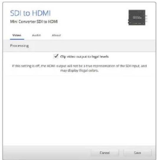
Onuia "Clip video output to legal levels" nncnojbyetc no ymonuaHIO.3To no3B0JeT aadantipoBaTb CnHan dIy BvBoDa chez HDMi-nHTepfeic.
Bknapka Audio nra Mini Converter SDI to HDMI daer BO3MOXHOCTb Bb1paTb ONcaHbte Hnke onuim.
MeHIO Output Levels
3To MeHIO No3B0JIeT yCTaHabINbAte b ypoBeHc CnHaHa aaynoBbxOe. HAcTpOKn MoKHO B6paTb dIy KaJdoro KaHana NO OTDeNbHOCTn, a cIIN HaKaTb 3NaUOK cKpeKN cnpBa O t CnaIepOB - IIN oBOx cxp3y. TTo6bl BepHyTBc K 3NaueHIno O nD nBcx HAcTpoE, HaxMITE Ha 3NaUOK c6poca B cTPOke Output Levels.
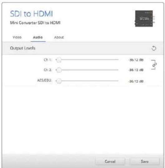
Bknadka Audio ytmntbl Blackmagic Converters Setup n03bONaTeYcTaHOBnTb ypOBeHb 3Byka
Cxema coeHneH Mini Converter SDI to HDMI
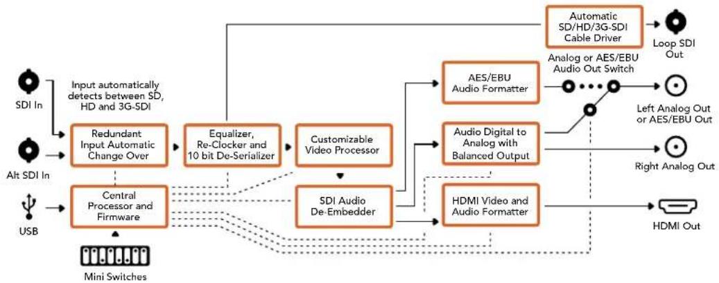
Mini Converter SDI to HDMI 4K
Model Mini Converter SDI to HDMI 4K and em modina to HDMI 4K Heavy Duty no3Boln intepcom. Mini Converter SDI to HDMI 4K abTomatneckn Bbipraet SD, HD n3G-SDI, BbnoHnnpoeobaoa HcHana co BCTpnaBaHem 3Byka n ero BbOdom Ha 6aHaChbn anorobn nn AES/EBU-BbxoD. FyHKnHDMI instant lock oecneuBaET nctoe nepeKnouHHe HA HDMI-BbxOe npCmHe nToHukOB COnnHakOBm fOpMaTOM BnDeo. Ecnn ha SDI-Bxod noctyaet cnHan B Ultra HD, a K HDMI-BbxOdy noklouen HD-MOHITop ntn TeBeN3Op, bndt ABtomatueckn BbInonHeHa NoHHXiaOua KOHBercn. To no3Bolnre npocmatpmbab TIObpaHne CBepXBicOKoi Yekocn Ha HD-ekpahe.
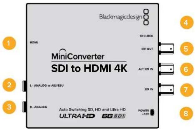
Pa3beMbl
1 HDMI
HDMI-BbIXoD TnA.
2 L-ANALOGnnnAES/EBU
Banachbna ananorobn (neBkahan) nnnu npoBoAES/EBU-aynoBixOc pa3bemom 1/4 duim.
3 R-ANALOG
BaIaHCHbI aHaIorOBbI ayDIOBbIXOd (npaBBi KaHJI) c pa3bEmOM 1/4 IouMa.
4 Nopt MINI-B USB
ObecneuBaET noKkHueHHe K KombIepey c onepaunHOHcNCTeMoM Mac OS X nn Windows dna paobTu CytunToB Blackmagic Converters Setup. TaKke cnxJnt dnna 6OBnBeHnBCTpOeHHoro IIO MmH-KOHBeptepa.
5 SDI OUT
SDI-BbixoC BNC-pa3beMOM.
6 ALT SDI IN
DOnonHnTeIbHbN SDI-BXoD IyDyBnIpOBaHnCnHaHa.
7 SDIN
OCHBHOI SDI-BXoI.
8 POWER +12V
Bxod nntaHn 12 B.
Pepekliouatei
COBET. Moenb Mini Converter Heavy Duty NMeet peHOByKpblkny dna 3auntb nepeknouatee. Hto6bI noynHT doCTyn KHN, nOHNMTe Kpbikky.
Mini Converter SDI to HDMI 4K imeeT nepeknioatei, c nmoocIO KOtOpbIX MOXHO Bbipapb pa3nHbHe HactpOKn pneo6pa3OBaHna.
IpeeknouateB 8-Analog Audio,AES/EBU Audio
YcTaHOBnTe nepeKniOuatEn 8 B noJoxeHne OFF (BbIKn.)yTObblBbODnTb banaHCbI anaIorOBbI 3Byk, nnn ON (BKn.) dIy nCnOJIb3oBaHnI cNΦpOBOr AOES/EBU-BbxOJa.
IpeeklouateIb 4 - SDI Audio De-Embed Bit 2
Ipeeknioateen 4,3 n 2 no3B0JrOHT NCIOB3OBaT BOCEm KOMbHaUON ON/OFF.Cnx NMOO Bo MOxHO Bb6paTb BOcEMpa3bIX nap ayDnOKaHAnOB,KOTOpbe 6ydyT BbIDeNeHb IN3 BXoAurero SDI-cnHana dny BbBOda Ha HDMI-nteppeuc,aHAnorOBb nnu cnpobou AES/EBU-pa3bembl.
Ipeeklouatelb 3 - SDI Audio De-Embed Bit 1
Cm. onncahne nepekniouateTn4.
Ipeeknouatenb 2 - SDl Audio De-Embed Bit 0
CM. onncanhe nepeeknouate 4.
IpeeknouateIb 1 - Processing Off/Processing On
TOT nepeknioateIb He nCnonb3yETc.
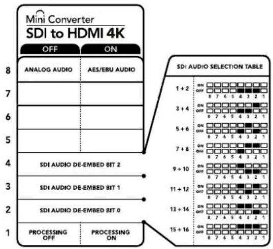
CxemaHaHnKHeN nobepxHocTN Kopnyca codepknt onncahne
Hactpoek, COOTBcTcBykUx pa3hbl NIOJoxeHNrM IpeeklouaTeNe
Ppimep hactpoek nepeekuoyateen
Ecnn n3 SDI-noToKa HyKHO BbIeJIb ayDnOKaHaJIb 1 n 2 dIy nx BbIOda Ha aHAnorOBbBbIXoJ, ycTaHOBIne nepeekuOateN 8,4,3 n 2 B noNoKeHne OFF (BbIKn.).
AydnookaHaJIbSI-DcHana
| AydinoKaHaJIbI | Пepeключatelь 4 Пepeключatelь 3 Пepeключatelь 2 | Положени пepeключatelя |
| 1и2 OFF OFF | ON OFF 8 7 6 5 4 3 2 1 | |
| 3и4 OFF ON | ON OFF 8 7 6 5 4 3 2 1 | |
| 5и6 OFF ON OFF | ON OFF 8 7 6 5 4 3 2 1 | |
| 7и8 OFF ON ON | ON OFF 8 7 6 5 4 3 2 1 | |
| 9и10 ON OFF OFF | ON OFF 8 7 6 5 4 3 2 1 | |
| 11и12 ON OFF ON | ON OFF 8 7 6 5 4 3 2 1 | |
| 13и14 ON ON OFF | ON OFF 8 7 6 5 4 3 2 1 | |
| 15и16 ON ON ON | ON OFF 8 7 6 5 4 3 2 1 |
Hacrtpoyn ytnnbl Blackmagic Converters Setup
Ytuna Blackmagic Converters Setup no3B0JET MeHb HAcTpoK MHH-KOHBePepa nOHOBnIb ero nporpAMHoe oecneHHe. DnA DOCTyna K 3TNM HAcTpoKam HcNoJIb3yIO T BknaKn Video, Audio n About.
Pa6Ota C BknaIkoJ About onncaHa B pa3dene «N3MeHHeHne HAcTpoE» DaHHoro pyKOBoCTBa.
BknaKa Video nra Mini Converter SDI to HDMI 4K daet BO3MOXHOCTb Bb6paTb onucaHHbIe Hnke onuH.
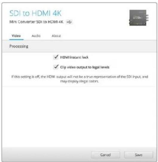
Onuia "Clip video output to legal levels" nnonbayetc no ymonuaHIO.3To noBONaT aadnnpoBaTB cHnAIN DnB BboDa uepea HDMi-nHTepfeic.
MeHIO Processing
HDMI instant lock
IocTaBbTe fIaKOK, TTo6bIakTbHApOBaTb FyHKUHO HDMl instant lock. Nocne 3toro daxepnpi CMeHe nCTOuHKnOB cRHaH bEydet noctynatb Ha HDMi-BbIXoD 6e3 nepepbBa, t. e. npBbOde n3O6paKeHnHa h kpaH HDMI-TeBEN3Op aNN MoHTopA NOBtOpHn yCTaHOBKa COeINHeHc PpHHMaIOUIM YcTPOJCTBOM He BbINOHNIEcA. FyHKUra paBOtaE1 TOIbKO B Tex cIyuaX, KOrDa NoCTyNaIOUee I3 nCTOuHKnOB BInDeo IMeet ODNHaKOBb CTaHdapt.
PnncnoIb3OBAHm fynKnn HDMl instant lock Bo3Hnkaet He6oJbWoe oTcTaBaHne 3Byka ot n3obpaXeHn. Ecnn Ha BbIXode Heo6xOJIMO IMEtB noNHyIO CnHXPOHn3aCIO BIneo n ayDIO, CHIMITE pnaKOK dIra TToI ONIIN.
- Clip video output to legal levels
3Ta onu nO3B0nAET aanTnpoBaTB BXOJaU SDI-cnHAn dIa BbBOdaYepe3 HDMInHTepdEic,No yMOnuHaHIO OHa DoJnxHa 6bTB BKIOueHa.
MeHIO Output Levels
3To MeHIO No3BOJnEET yCTaHaBnBaT b yPoBeHb CnHaHa Ha ayDnOBbxOHe.HAcTPOIKN MOXHO Bb6paTb dIy KaJdOro KaHana N O TdEnbHocTn, a ecN HaxaTb 3NaUOK cKpeKn CnpabaOT cIaNepOB - dIy oOON cpa3y. YTo6bl BepHyTbcra K 3NaueHnO O D5 dIy BceX HAcTpoE, HaxMITE Ha 3NaUOK c6poca B cTPOKe Output Levels.
BknaKa Audio nra Mini Converter SDI to HDMI 4K daet BO3MOXHOCTb Bb16paTb ONICAHHbE HIXe ONUIN.

Bknadka Audio ytmntb Blackmagic Converters Setup no30bnraet yctahOBnTb ypoBeHb 3Byka
Cxema coeHneH Mini Converter SDI to HDMI 4K
Mini Converter SDI to HDMI 6G
3TOT MHNKoHBePTeP no3BONJeT bVbOuNTb H3o6paKeHne c SDI-06OpyDoBaHnHa HnCnneu Hn BnDeonpoeKToPb c HDMI-HnTepeFcM. Mini Converter SDI to HDMI 6G aBtOMaTuYeckn nepeKnUoyaeTc Mekdy SD-SDI, HD-SDI, 3G-SDI n 6G-SDI Ha BxOe, o6ecneHnBaJ npoeobpazOBaHne B HDMI-crHaCo BCTpoEHbIM 3BykOM, a TaXke BbBoDHT ayDnO Ha BaJaHChbI AES/EBU-nnn aHaNoorBbBbXoD.
Функцин HDI instant lock obecnueuBaet nuctoe nepeknouhene Ha HDM-Byxoide npi cmene nToCHIKOB COnHakOBbIM fOpMaTOM BIneo. EcnHa SA Dl-BxOIOCTyNaET cRHaN B Ultra HD, aK HDMI-BbXoDy NOkNoUeH HD-MoHHTOP mTNTEBUNOp, bYdET ATOMATUeCKN BbINONHeHa noHHaJoua KaOHBepcn. 3To No3BOJrE TPOcMaTpNBaTB N3O6paxHeNe CBepXBICOKO YeTKOCTn HA HD-3KpaHe.
ДлгцьETOBоOobOTKcHrHаHa BbIXOe MoXHO NcNoIb3OBAbT 3D LUT-taBnUcbl. OHH npEcdTbIaHOT cOBo MATpNcbl Ha OCHObe 33 KoOpdHaTHbIX TOeK, KOTOpbIe No3BOJIaHOT Ha annapaTHOM yPoBHe BbINONHtB MaHInyJLmC CZbETOM I pOBODITb KaINbPOBky bItOBbIX TeIeBn3OpOB npeI rpeiHrom.C NOMoUbIO 3D LUT-taBnUcbl IerKO BbINOnHITb npoeOpa3ObaHne ZcBTOBOrO npocTaPcHCTBa dJa paObToI c pa3HbIMn DcNcIpeMm. Mini Converter SDI to HDMI 6G Imeet dBe npEydctAHOBHeHHbIe LUT-taBnUcbl: dJa npoeOpa3ObaHnra ZcETHorO n3OpaKeHnB V cepHo-6enoe I dJa KOHBepTIpObaHnB VIeDe O c kamep Blackmagic B zEBTObe npocTaPcHCTBO REC 709.
Pa3beMbl
1 HDMI
HDMI-BbIXOJ TnA.
2 L—ANALOG nnn AES/EBU
BaanhcBn ananorobBn (neBn kaHn) nnn cnpboB AES/EBU-aynoBbIXoC pa3bemom 1/4 nOma.
3 R-ANALOG
BaanchbnaHANOBOBMyaynOBbIXO(npaBBKaHa)cpa3bEmOM1/4IOIma.
4 Nopt MINI-B USB
ObecneuBaET noKluHcHHe K Komblotepy c onepauHNoHcNCTeMoM Mac OS X nn Windows dny paobTy cyTnHToB Blackmagic Converters Setup. TaKke cnKynt dn 6HOBHeHb BCTpoEHHOro PO MmH-KOHBeptepa.
5 SDI OUT
SDI-BbIXoC BNC-pa3bEmOM.
6 ALT SDI IN
Дононтелов SDI-BxOD Дубларова сигнala.
7 SDIN
OCHBOHSDI-BXoD.
8 POWER +12V
Bxod nitaHn 12 B.
Ipeeknloatei
Mini Converter SDI to HDMI 6G imeet npeeknouateen, c nomoocio kotopbix moxHO bio paTa pa3nuehhe hactpokn npoeoopa30aHna.
IpeeknouateB 8-Analog Audio,AES/EBU Audio
YcTaHOBtnepeKIOUaTeIb8NnOxKeHHeOFF(BbIKn.)yTObblBbOuNTb6aHaCHbI anAHOBbI 3Byk,nnON(BKn.)dnaNCnOJIb3oBaHnueNfpoBoroAES/EBU-BbxOda.
IpeekkoyateNB- BkIOUeHne n OTKIOUeHne LUT-ta6nucbl
YctaHOBtpe nepeKIOUATEb 7 B noLOXeHne OFF (BbIKn.), yTObI OTKIOUHTb LUT-taBNIu, nIN B noLOXeHne ON (BKn.) dNee ee BKIOUeHn.
IpeeknouateB6-Bb6op LUT1nnLUT2
YctaHOBtnepeeknouateIb6BnoJoxeHne OFF (BbIK),yTO6blncnoIb3oBaTb Ta6nU LUT 1,nn B noJoxeHne ON (BKn.),yTO6blb6paTb Ta6nU LUT 2.
IpeeknouateIb 5 - BkIOueHne n OTKIOueHne LUT-ta6nucI ha CKBO3HOM BbIXOe
YcTaHOBInTe nepeKIOUaTeIb 5 B noLoXeHne OFF (BbIKn.), YTO6bI OTKIOUHTb LUT-Ta6NtuHaCKBO3HOM BbIXOe, INB nIoXeHne ON (BKn.), YTO6bI NCNoJIb3OBaTb LUT-Ta6NtuHa 3TOM BbIXOe.
Ipeeknouateb 4 - SDl Audio De-Embed Blt 2
Ipeeknioateen 4,3 n 2 no3oBnAIOT nCnoB3OBA Tb BOCem KOMnHaUON ON/OFF.Cnx nMOoubmoxHO BbIpaTB BOCem pa3HbIX nap ayDnOKaHAnOB,KOTOpBie bdyT BbIeNeHb IN3 BXOJaeroSDI-cnrHana dna BbIBoDa Ha HDMI-nHTeppeic, aHAnorOBb nnu cnpboBn AES/EBU-pa3bEmbl.
IpeeknouateB3-SDI Audio De-Embed Bit 1
CM. onncaHne nepeKIOUOATEN4.
IpeeknouateB 2 - SDl Audio De-Embed Bit O
Cm. onncahne nepeknouateTn 4.
IpeeklouateIb 1-BKIOUeHne IOTKIOUeHne FyHKcHn HDMl Instant lock
UcTaHOBnTe nepeKIOuATeIb 1 B noIOxHne OFF (BbIKn.) yTOb6I OTKIOuHTb FyHKnIO HDMl instant lock, nII B noIOxHne ON (BKn.) yTOb6I nCNoJIb3OBA Tb 3Ty FyHKnIO.
Bo BTOPOM pEXKIMe DAXe npn CmHe NCTOCHNKOB CnHAn 6yTeNtNoCTynatb Ha HDMI-BbXoD 6e3 nepepbIBa, T. e. npn BBIOBe I3oBpaXeHnHa 3kpan HDMI-TeLEBn3opa nnn MoHTopa NOBTOHPaYcTaHOBA CoeINHeHnC PpHnHMaKOuMg YcTPOJCTBOM He TpeSyetc. FyHKun paBotaET ToIbko B Tex Cnyqayx, KOrDa NoCTynaiOoiuee IN 3 NCTOCHNKOB BIneo IMeET OndHaKOBbl CTAHapT.
PnncnoB3OBaHm FyHKnH HDMl instant lock Bo3Nkaet He6oJbwoe otCTabAHne 3Byka OT nO6paKeHH. Ecnn Ha BixOe Heo6xOJMo NMeTb NOnHyCnHxPoHN3aUIO BInDeo n ayDNo, OTKIOHTe 3Ty ONIIO.
CxemaHaHnKHeN NOBepxHOCTu KOpnyca coepknt OINCAHNE HAcTpoek,COOTBEcTByKOUX pa3hBM NIOXKeHNmpeekNIOUaTeNo
Pnimeh hactpoek nepekeuoyateJe
Ecnn n3 SDI-nOToka HxKHO BbIeNITb ayDIOKAHaJIb1 n 2 dnn IX BbIBOHa Ha aHANOBOB bBIXoJ, yctahOBte nepeKNIouateen 8,4,3 n 2 B noNoKeHne OFF (BbIK).
AydnookaHaJIbSI-DcHana
| AydinokanalbIпepeklnouateNB 4пepeklnouateNB 3пepeklnouateNB 2 | Положени пepeklnouateNB | |||
| 1 and 2 OFF OFF | ON OFF 8 7 6 5 4 3 2 1 | |||
| 3 and 4 OFF ON | ON OFF 8 7 6 5 4 3 2 1 | |||
| 5 and 6 OFF ON OFF | ON OFF 8 7 6 5 4 3 2 1 | |||
| 7 and 8 OFF ON | ON OFF 8 7 6 5 4 3 2 1 | |||
| 9 and 10 ON OFF | ON OFF 8 7 6 5 4 3 2 1 | |||
| 11 and 12 ON OFF ON | ON OFF 8 7 6 5 4 3 2 1 | |||
| 13 and 14 ON ON OFF | ON OFF 8 7 6 5 4 3 2 1 | |||
| 15 and 16 ON ON | ON OFF 8 7 6 5 4 3 2 1 | |||
HacrpoKu yTnntbI Blackmagic Converters Setup
Ytuna Blackmagic Converters Setup no3B0n8eT MeHb HAcToPmMHNKoHBepTepa n oHOBaIb ero nporpamMHOe oecneueHne. IaIOCTyNA K 3TNM HAcToPmKAM NcNoJIb3yIOT BknaK Video, Audio n About. PaOta c BknaKo Aobut onucaHa B pa3dene «NImehHe NaCTPOeK» daHHoro pyKOBOcTBa.
BknaKa Video dnia Mini Converter SDI to HDMI 6G daet BO3MOXHOCTb Bb16paTb onucaHHbE HnKe onu.

Onuia "Clip video output to legal levels" nnonb3yctc no ymonaHIO.
3To no3B0n8eT aanTpOoBaT bCnH an dny BbBOda uepea HDMI-ntHepeic.
MeHIO Processing
3D LUT Ha ochobe 33 ToeK
Mini Converter SDI to HDMI 6G noДержИBaet paOToC faiNam. cube, KOTOpBte MoKHO co3dA b c nOmoBbD DaVinci Resolve nIIN dpyrO npnIOxENH nI ZBeTOKPpeKmN.
KoHBeptep no3B0n8e 3aRpy3ntb DBe pa3HbE LUT-tabNcbl.ДЯ nToTO HaxMITE COOTBeTCTByUOyIO KhoNky Load, Bb6epNTe faan . cube Ha KomMbItepe n HaxMITE OK. HaxMITE Save, yTo6bl noDTBePNTb Bb6op. ImeHa fainOB OTobpaKaIOTc prdOM C KhoNkoi Load, NO3TOMy Bbl BceTa 6yTe 3HaTb, KaKne I3 HIN NcNoJIb3yOTcra dIra onuLUT1nLUT2.
- TpexMepna LUT-ta6nua
3D LUT - 3TO faan c Tpexmepno Tabnuei 3HaueHn Ira n3MeHeHna CBETOBOR npoctpaHCTBa.
MaccnB daHbIX cOepKHT TOKN, nCNoJIb3yEmBe dIg Ipeo6pa3OBaHnK KaJIORO OCHOBHO rBaTe C nOMOJIbIO KoOpDnHaT X, Y n Z. TaKIM o6pa3OM, dIg cyUeCTByIOuIX 3NaueHn Kpachoro, 3eJeHOrO n CInHeRo KaHaIOB Ha SDI-BXoDE MoXHO 3aDaTb HOBbE 3NaueHn Ha HDMI-BbIXOJe. POnO6HnA yHKcNRA BnReTcMaOUIbIM INHCTpyMeHtOM dIg NCKLIQUHTeJIbHO ToHOr KaIIb6PobKn DnICIIeEB n 3aRpy3Kn KpINbIX raMMaPacnPpeDeHEnH, KOrDa Heo6xOdIm OueHnTB IIHeHHyIO rAMMy npi paOte C pa3NIuHbIM TUNAMn faiNob RAW.
OHa n3 3aRpykaembIX no yMOnuahnIO TpexMepehbx LUT-tabnuc no3BONReT KOHBeptInpoBaTB CBETHO BnDeo Ha BXode B cepHo-6eNoe Ha BixOJe. Bce 3NaueHnKpaCHoro, 3eHeRo i CnHrero KaHAnOB B NoCTynaIOUe M CnHane NOyuaIOT 3NaueHnCOoTBcTByOuIe UepHo-6eNoMy N3O6paXeHIO B NCxOJaUe CMHane. PnINOKeHne DaVinci Resolve daet BOzMOxHocTB CoXpaHHT bCBETOBYIO CXEmy BnDE LUT-tabnblNMMopTnpoBaTB ee Ha Mini Converter SDI to HDMl 6G c nOmoBu npOrpaAMmHOyTNNTbl. TaKxe DOnyckaTeC npImeHHeNE 3D LUT-tabnUbHa cKBo3Hom SDI-BbIXOe. B 3tOM cnUyae KOHBeptEep BbINOJIraT cBeTOByo OcbapOtky 6e3 nCnoJb3ObaHn HDMlBbIXOda.
- Clip video output to legal levels
3Ta onuia no3Bolner aadantnpobatb BxOaun SDI-cnHan nBbOda uepe3 HDMInHTepfeic. No yMOnuahnO OHa dONJHa 6bItb BKIOueHa.
MeHIO Output Levels
3TO MeHIO no3B0JAEYcTaHaBnBaTb yPoBeHcHrHa Na ayDnOBbIXOe. HAcToPmKMOxHO BbpaT dIy KaXdOro KaHana No OTdEhBOCTN, a ecn HaKaTb 3aHoc KcpENKn Cnpaba O cIaIepOB -IIN o6oNxCpAzy. YtobblpeHyTBcR 3HaueHnIO O d5 dnn BCex HAcTpoE, HaxMITE Ha 3HaQOK c6pOCA B cTPOKe Output Levels. BknaKa Audio dIra Mini Converter SDI to HDMI 6G DaET Bo3MOxHOCb TbBpaT bOncaHHbI He NHXe OnuIN.
Bknadka Audio ytmntb BlcKmagic Converters Setup no3Bonrct yctahOBnTb ypoBeH 3Byka
Cxema coeHneH Mini Converter SDI to HDMI 6G
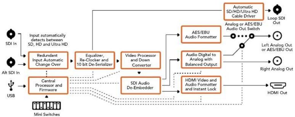
Mini Converter HDMI to SDI
Modenb obecneuBaet BvBOD HDMi-cirHana irpoBbIX KOHcnei HDV-kamep Ha yctpoIcTba c SDI-nHTepfemcom, a TAKKe no3BOJnE BCTpaBt 3ByK, noNyHeHHb i C HDMl-, AES/EBU- nIb balaHCHoro aHaIorOBTO BXoOB. BnaOapra 3OMy MoXHO nepeDaBt N3OpaKeHne n3 HDMI-ntouHnka nO SDI-ka6eHNo ha 6oJIbWoep pacCToRHe, a TAKKe noDKIIOaTB KOMNbOTep K SDI-obopyDobAHnIO. KoHbepTe IOnONHInTeBHO nOIIepxNBAe T OHNJaIOyIO KOHbepCnIO n3 HD B SD.
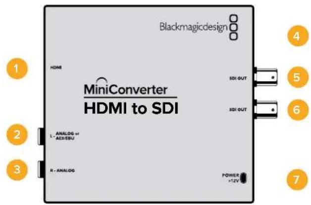
Pa3beMbl
1 HDMI
HDMI-BXoD TnnaA.
2 L-ANALOG nn AES/EBU
BaIaHcHbI aHaIorOBbI (neBbI KaHaI) IIN cUΦpOBoA EAS/EBU-aynIOBXoD c pa3bEmOM 1/4 IIOIMa.
3 R-ANALOG
BaIaHcHbI aHaIorOBbI ayDIOBxO (npaBbI KaHaI) c pa3bEmOM 1/4 IouMa.
4 Nopt MINI-B USB
ObecneuBaet noKnIoueHne K Komblotepy c onepauonHOn cncTeMo Mac OS X nn Windows dny paobTo cyntnToBkMaigc Converters Setup. TaKke cnkynt dnna 6OBHeHb BCTpoEHHO rMO MNHN-KOHBeptepa.
5 SDI OUT
SDI-BbIXoC BNC-pa3beMOM.
SDI OUT
Btopoi SDI-BbIXOa
7 POWER +12V
Bxod nHTaHn 12 B.
Pepeknloatei
Mini Converter HDMI to SDI nmeet nepekniouatei, c nmooukoTOpbIX MOXHO BbipapTa pa3nHbHe HactpoKn pneo6pa3OBaHna.
Ipeeklouateb 8 - Analog Audio, AES/EBU Audio
YctaHOBtne nepeknHouateIb 8 bnoJoxeHne OFF (BbIKn.)yTObblbOpaTb 6aHaHCHbI aHaIOROBbI 3ByK,nn ON (BKn.) dna nCnOJIb3OBAHnA EAS/EBU-BXoJa. YTObI paBOTaTb C 3TmN BxOdAmn, nepeknHouateIb 7 doJxeh 6bITb yCTaHOBHeB noJoxeHne ON (BKn.).
Ipeeknouateb7-HDMI Audio,Input Audio
YctahOBITE nepeKNIouateIb 7 B noIOxHeHne OFF (BbIKn.), YTO6bl NCNoJIb3OBA Tb 3ByK, BCTpoEHbI b HDMl-CnIHan. Iyra paBoTb c aHaIoroBbIM nn AES/EBU-ayDIO BBiBepuTe noIOxHeHne ON (Bkn.).
Ipeeknouateb1 - Processing Off/Processing On
IpeeklouateIb 1 no3Bolrae T b6paTbp nponopu KaDp npn BblnoHeHn noHHaOeKoHBepcnn n3 HD B SD. Hanpimep, npn KaKdoynctahOBKe nepekluateTbn noLoxHeN ON (Bkn.) nCnoJIb3yETcOOn Hn n3 Tpx pex peKmOB: anamorphic, center cut nn letterbox. Pnp noLoxHeN OFF (BbKn.) noHxaOuaa KOnBepcn He BblnoHreTc, noToMMy h BaixodocTynaet HD-cunHan.
PnnoNkIIOeHmKOMbIOTepy uepe3 npT USB hactpoKaMn ynpaBnaIc nMOUbO yTNNTb Blackmagic Converters Setup. Ecn Heo6xOIMMo coXpaHnTB bIbpaHHb peKIM,OTcoEHNHTe KOHBepTe OT KOMbIOTepa,OTKIOHTe IN CHOBA BKNIOHTe NtAHe, a 3aTeM yCTaHOBIne HACPoKn POnHKaIOSeI KOHBepCn C NOMOJIbIO nepeKIOUcTeTn1.
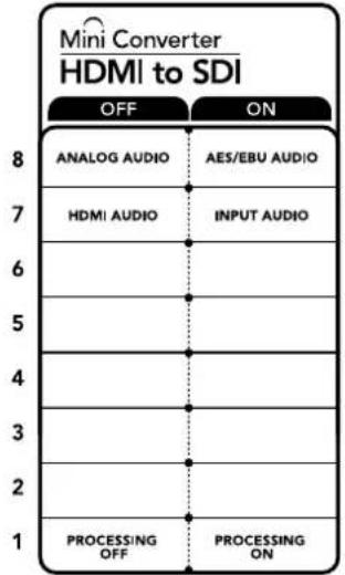
CxemaHaHnKHeNIOBepxHOCTKOpIyCa coepXHTOINCAHHe HAcTpoE,COOTBeTCTByIOUHX pa3HbIMNOJoxEHm IpeeknouateNe
HacrtpoKn yTnntbI Blackmagic Converters Setup
Ytnta Blackmagic Converters Setup no3BnReT MeHrTa HAcToKn MmH-KoHBeTepa nOHOBnIb er o nporpamMHOe obecneueHHe.ДЯdoCTyNA K 3Tm HAcToKa m NcNoJIb3yIOT BklaKn Video, Audio n About.
Pabota C Bklaakoi About onica H pa3dene IImeHne HaTpoek DaHHoro pyKOBODBa.
BknaKa Video dnia Mini Converter HDMI to SDI daet BO3MOXHOCTb BbOpaTb ONCAHHBe HnKe ONCN.
MeHIO Processing
3To MeHIO No3BOJnAET BbIbnpaT nponopuKApna pnpBbINONHeHm NOHNJaOe KOBHepcn n3 HD B SD. DocTyHbIe onu: Letterbox, Anamorphic, Center Cut n OFF (BbKn).
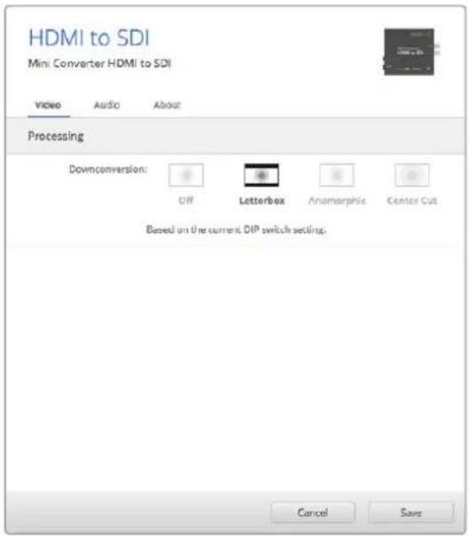
Bkna Video ynnnbl Blackmagic Converters Setup no3B0n8ET Bb6paTb HcTePouKn npeo6pa3ObaHn
Bklaika Audio dIra Mini Converter HDMI to SDI daet BO3MOXHOCTb Bb6paTb onncaHHhe Hnke onu.
Mehio Input Levels
3To MeHIO No3BONJETyCTaHaBnBaTb yPoBeHc CnHana Ha ayDnOBxOJe. HAcTpOKn MoXHO Bb6pTa DnA KaJdOro KaHana N O TdEnbHOCTN, a cCIn HaxaTb 3HaouK cKpeKN cnpBa OT CnaIepoB —ДЯ obOnx cpa3y. YToBb BepHyTbcR K 3HaueHnO O d5 dnn BceX HAcTpoEk, HaxMITE Ha 3HaoyK c6poca B cTpoke Input Levels.

Bknadka Audio ytmntbl Blackmagic Converters Setup no3BONaERyCTAHOBnTb yPOBeHb 3Byka
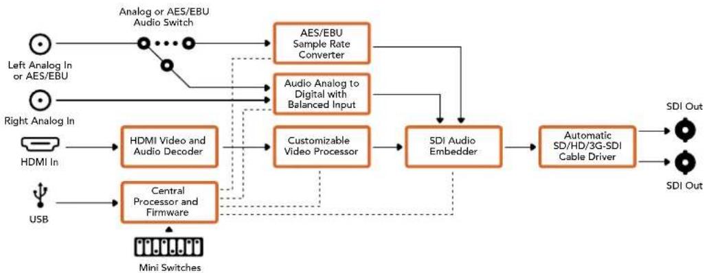
Cxema coeHHeH Mini Converter HDMI to SDI
Mini Converter HDMI to SDI 4K
MoeB Mini Converter HDMI to SDI 4K n ee moiNnkaaHDMI to SDI 4K Heavy Duty oBeceuBaot BvBod HDM-Cirhana irpoBbIX KOHcOe i HDV-kaMeP ha yctpoCTBa c SDIInHTepfemcom, a TAKKe no3BOJAAOT BCTpAnBaT 3ByK, noLnyeHHbI C HDM-, AES/EBU-niB6aHaCHoro aHaNoRORoBO RxODOB. BlaRoDapr AToMy MoXHO nepeDaBaT bI3OpaXeHne I3 HDMI-ntouHnka no SDI-KabEnIO Ha 6oJIbWoE paCtOAHne, a TaKKe NoKnHouaTb KOMNbIoTe pK SDI-06OpydoBaHIO.
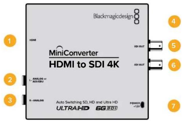
Pa3beMbl
1 HDMI
HDMI-BXOД TUNA A.
2 L-ANALOGnnnAES/EBU
Baanhchb aHaonobb aynoBxOa (neBb KaH) nnuΦpOoaynOBxOAES/EBU cpa3bemom 1/4 duim.
3 R-ANALOG
BaIaHcHbI aHaIorOBbI ayuIOBxOI (npabI KaHaI) cpa3beMOM 1/4 JIOIma.
4 Nopt MINI-B USB
ObecneuBaet noKnHoueHnK Komblotepy c onepauonHouc nctemOa Mac OS X nn Windows dna paobTu CytunToB Blackmagic Converters Setup. TaKke cnxNt dn naOBHeHn BCTpoEHnro IIO MNH-KOHBeptepa.
5 SDI OUT
SDI-BbIXoC BNC-pa3beMOM.
6 SDI OUT
Btpoi SDI-BbIXoJ.
7 POWER +12V
Bxoi nita 12 B.
NepeknlouataeI
COBET. Moenb Mini Converter Heavy Duty NMeet peHOByIO KpbIuKy dna 3aunTbI nepeKluoyateJe. TTo6bl NoUyHTb DocTyN K Hm, POnHMnTe KpbIuKy.
Mini Converter HDMI to SDI 4K nmeT nepeknoyateN, c nmoocIO KOtOpbIX MOXHO BbInpaTaB pa3nHbHe HactpOKn ppeo6pa3OBaHna.
IpeeknouateB 8 - Analog Audio, AES/EBU Audio
YctahOBtne nepeKIOUaTeB 8 nNoXeHne OFF (BbIKn.),TTO6bl BbIpaTb GanaHCbH aHaIorOBbI 3Byk,nn ON (Bkn.) dna nCnoNb3ObaHnA EAS/EBU-BxOda. YTO6bl paOtaTb C 3TmN BxOdaMn, nepeKIOUaTeB 7doJIkeh Oblb YcTaHOBHeB nNoXeHne ON (Bkn.).
Ipeeknouateb 7-HDMI Audio, Input Audio
YcTaHOBnTe nepeKnIOuATEb 7 B noIoxeHne OFF (BbIKn), yTO6bl NCNoNb3OBA Tb 3Byk, BCTpoEHbH b HDMi-cnHan. Dnra pa6oTb C aHaIoroOBbIM nn AES/EBU-ayDIO BB6epnte noIoxeHne ON (Bkn).
Ipeeknouateen 2,1-Select Format Bit 1,0
Pn npoknyen HDMI-ctouHka, cnoocbo BbBodntb Ultra HD n HD, 3a hactpoKa nomoraet npinynteBHO nCNoBzOBaTb hyxHyIO yETKoCTb. 3a onuia MoKeT 6bITb noE3HoJ, KOrda n3obpaxHe C kOMNbIOTepa Heo6xOdmo 3anncatb nn npocmotpeh Ha SDI- o6opydoBaHn B HD-pa3peweHn.
XOTI NOUYAEMBI 3000KIOXHO NOBIIaIOUHO HIN NOHIXaIOUHO KOHBepCIOHO CAOMO
Dene KOHBEPTEOP TnpabNIEITocOHky KOMaHy BbBOIDtBnDeo B Ultra HD nH HD. B 30m
cnyae noCTynaIOUI CnHAnpepaETcRa H BbXoJ 6eONONHTeBHorO poeobp3OBAHNA
IcnoIb3yOnpeHEnHHyKOM6nHaunIO nepeKnUoateNe12,MOxHO BbIpaTb npHynteBbHbBbBOB B HD nIIu Ultra HD nio aBtOMaueckoe onpeHene ONTMaJIbHor pa3peWeHn.
Hnke onncahbI Bo3MOXhBie BapnaHTbHaCTpoKn.
AUTO - nepekIIOUaTeHn 1 n 2 B noLoXeHn OFF (BbIK.).
KoHBeptep aBtOMaTnueeCKn onpeDeneT ontImaIbHoe pa3peuHHe (HD nII Ultra HD) B 3aBNCMOCTN OT TEXHnueeCKNX xapakTePncNTN UCTOHNKA CnHaHa.
FORCE TO HD - nepekliouateIb 1B noIooxeHn OFF (BbIKI.). nepekliouateIb 2 B noIooxeHn ON (BKnI.).
EcnHDMI-nctouHKnnoepxmbaetbBIOBnBDnUltraHD, KOHepep 6ydt nnyatb HD-cunHan.
FORCE TO ULTRA HD - nepekniouaTeNb 1 B noIooxeHn ON (Bkn.), nepekniouaTeNb 2 B noIooxeHn OFF (BblKn.).
EcnHDMI-nctouhN noDnepxnae T bBIOB H D n Ultra HD, KOHBeptep 6ydt noLyuatb Ultra HD-cnHaJ.
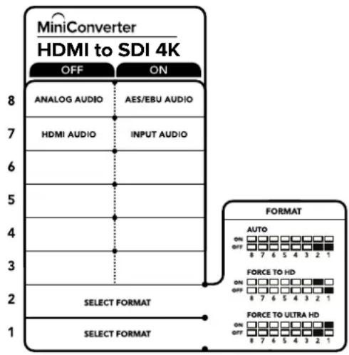
CxemaHaHnKHeNoBepxHocTH KopnyCa codepknT onncAHne Hactpoek, COOTBetCTByIOUX pa3hBM nONoXeHNrM nepeKIOuateNei
Hac trokn ytnntbI Blackmagic Converters Setup
Ytuna Blackmagic Converters Setup no3BONaET MeHb HAcTpoK MmHn-KOHBePepa nOboHbIb ero nporpaMMHoe oecneueHne. DnA DocTyNA K 3TNM HAcTpoKam NcNoJIb3yIOB BklaKn Audio n About.
Pa6oTa C BklaaKo About oncuHa B pa3dene «I3meHHe HacTpoeK» daHHoro pykoBocBa.
BknaJa Audio nla Mini Converter HDMI to SDI 4K daet Bo3MOXHOCTb Bb16paTb onncaHHbE Hnke onu.
Mehio Input Levels
3To MeHIO No3BOJnREYCTaHABINBAtyPObEh CnHana Ha ayDnOBxOe. HAcTpoKm MoXHO Bb6pTaB DnKaJDoR KaHaHa N0 OTdEJIbHOCTn, a cEmn HaxKaTb 3HaUOK CkpeKN Cnpaba O TcnaIepOB - DnA Oboux cpaay. YTo6bI BepHyTBcK 3HaueHnIO O d5 dNra BceX HAcTpoE, HaxMITE Ha 3HaUOK C6poca B cTPOKe Input Levels.

Bknadka Audio ytmntbl Blackmagic Converters Setup no3BONrReYcTaHOBnTb ypoBeHb 3Byka
Cxema coeHneH Mini Converter HDMI to SDI 4K
Mini Converter HDMI to SDI 6G
Modenb obecneuBaet BbIbOD HDMi-cirHana irpoBbIX KOhcone n HDV-kamep Ha yctpoicTba c SDI-nHTepefcom, a TAKKe no3BOJraRET BCTpaNBaTB 3ByK, noNpyehnbl C HDMl- AES/EBU- nlaahCHoro ananorOBOr BXoOB. Bnaorapr atomy moKHO nepeDaBaTB n3obpaXeHne n3 HDMI-nCTouHnka no SDI-kabeHIO ha bOJIbwoe paCtToHne, a TAKKe noKnluOaTB KOMnbIOTep K SDI-obOpydoBaHHIO.
Pa3beMbl
1 HDMI
HDMI-BXOD TUNA A.
2 L - ANALOG nnn AES/EBU
BanaHcHbI aHaIorOBbI ayDIOBxOJ (neBbI KaH) nnu cnpoBoI ayDIOBxOJ AES/EBU c pa3beMOM 1/4 duIma.
3 R - ANALOG
BaHaHcHbI aHaNoRObBMyaynOBxO (npaBbI KaHaI) c pa3bEmOM 1/4 IouMa.
4 Nopr MINI-B USB
ObecneuBaet noeknueHene K kombIotepy c onepaunHOHcNCTeMoM Mac OS X nn Windows dna paobTo CytINrOa Blackmagic Converters Setup. TakaKe cnXnT nnoHBnEHHBCTpoeHHoro PO MmH-KOBHeptepa.
5 SDI OUT
SDI-BbIXoC BNC-pa3beMOM.
SDI OUT
Btopoi SDI-BbIXOa
7 POWER +12V
Bxod nHTaHn 12 B.
Ipeeknloatei
Mini Converter HDMI to SDI 6G UmeetnepeKIOuatae, c nOoUIO KOtOpbIX MOXHO BbIpaTb pa3nHHe HactpOn Knpoe0b0aHaHna.
Ipekekniouatene 8-Analog Audio, AES/EBU Audio
YctaHOBtne nepeKIOUATeB 8 nOJoxHeN eFF (BbIKn. YTO6b BbIpaTb bAnHChb aHaIorOBbI 3Byk, mN ON (BKn.) dN IcIIb3ObaHnA EAS/EBU-BXoJa. YTO6b paBOTaB C 3TmMn BXoJamn, nepeKIOUATeB 7 doJKeH 6bITb yCTaHOBNeH B noJoxHe N ON (BKn.).
IpeeknouateB7-HDMI Audio,Input Audio
YctahOBITE nepeKNIHouateIb 7 B noIOJKeHne OFF (BbIKI), HTO6blNCIOJIb3OBA Tb 3ByK, BCTpoEHbH B HDMI-cnIHan. Jra pa6oTb c aHaNoRObbIM nn AES/EBU-ayDIO BB6epuTe noIOXeHne ON (Bkn).
PepeknioateB6-BbIbOp ypOBH npn BbIObe 3G-cnrHa
YctaHOBtnepeKIOUcATEb 6 B noIOXeHHe OFF (BbIKn.), YTObI ncNob3ObaTb Level B, nn ON (BKn.) dIra paOToIc Level A.
Ipeeknouatei 2,1-Select Format Bit 1,0
Pn npoknyehn HDMI-ntOchNka, cnocoboro BbIOBntb Ultra HD n HD, daHna Hactpoika nomoraet npinyntteho hncnoIb3oBaTa hyxHyIO ueKoCTb. 3a onuia MoKeT 6bItb none3HO, KOrda n3obpaXeHne c KomIbIoTepa Heo6xOdmo 3anicaTb nn npocmotpeh Ha SDI- obopydoBaHH n BD-pa3peweHH.
XOTI NOUYAEMBI 3000K TNOOX HA NOBbIaIOUHO HIN NOHIXaIOUHO KOHBepCIO, HA cAMOM
Dene KOHBepTeP OITnpABnIeT NcTOHnky KOMaHy BbBOIDtB BuDeo B Ultra HD nH HD. B ATOM
Cnyuae NoCTyNaIOUI CIRHan nepeAdetc Ha BbIXoD 6eONONHTenbHorO poeobpa3OBAHnR.
IcnoIb3yOnpeHEnHHyIO KOM6nHaUIO nepeKIOuATEeNE 1N2,MOxHO BbOpaTb npHyDntelBbHbBbBOd B HD nIIu Ultra HD nIO aBtOMaTneckoe onpeHEnHe ONTMaJIbHoro pa3peWeHn.
Hnke onncahbI BO3MOXhBie BapnaHTbl HaCTpoKn.
AUTO - nepekIIOUaTeHn 1 n 2 B noLoXeHHN OFF (BbIKn.)
KoHBeptep aBtOMaTnueeCKn onpeDeneT onTImaIbHoe pa3peuHHe (HD nIu Ultra HD) B 3aBNCIMOCTN OT TEXHnueeCKNX xapakTePncNTK NCTOCHNA CnHaHa.
FORCE TO HD - nepekliouateIb 1B noIooxeHn OFF (BbIKl.), nepekliouateIb 2 B noIooxeHn ON (Bkn.)
EcnHDMI-nctouhnik noedepxnaet BbIOB H Dn Ultra HD, konbeptep 6ydt nojuyatb HD-CnHaJ.
FORCE TO ULTRA HD - nepekniouatae1b 1B noIoxeHNN ON (Bkn.), nepekniouatae1b 2 B noIoxeHNN OFF (Bbln.)
EcnHDMI-ntOchHK noDepKnaBcT BbIOB H Dn Ultra HD, KOHBePTepeydt nolyaTaB Ultra HD-cunHan.
CxemaHaHnKHeiNoBepXHoCTKnKopnyCa coepKHT onncAHne HAcTpoek, COOTBeTCTByIOuNX pa3HbIM IIOLOXKeHNrM nepeKNIouateNe
Hac trokn ytnntbI Blackmagic Converters Setup
Ytnta Blackmagic Converters Setup no3B0n8e MeH8b HAcTpoKm MHNH-KOHBepTepa nOBHnIb ero nporpaMMHoe oecneueHne. IJn doCTyNa K 3TNM HAcTpoKam NcNoJIb3yIOT BknaKn Audio n About. Pa6ota c BknaNko About onncana B pa3dene «N3MeHeHne HAcTpoEe DAnHOrO pykoBocCTBa. BknaJaA Audio nJr Mini Converter HDMI to SDl 6G daet Bo3MoXHoCTb BblpaTb onncAHHbe HnKe onuIN.
Mehio Input Levels
3To MeHIO No3B0JIeT yCTaHabnBaIbTypoBeHc rHana Ha ayDnOBxOJe. HAcIpoK MoJHO Bb6paTb dIy KaJdoro KaHana NO OTDeNbHOCTn, a cIIN HaKaTb 3HaUOK CkpeKN CnpBa O cIaIepoB — IJIy oboix cpa3y. YTo6bl BepHyTBcR K 3HaueHIno O nD Iy BCex HAcIpoE, HaxMITE Ha 3HaouK c6poca B cTPOKe Input Levels.
Bkana Audio yuHnHb Blackmagic Converters Setup no3Bnonet yCTaHOHTb yPOeHb 3Byka
Cxema coeHneH Mini Converter HDMI to SDI 6G
Mini Converter SDI to Analog
Modenb Blackmagic Mini Converter SDI to Analog obecneuBaet npeoobzOBaHne cunha SD/ HD-SDI B aHaIorOBoe KOMnoHeHTHOe BVJeO, NTSC u PAL C bVBOOM 6aHaCHOrO AES/EBU-n aHaIorOBOrO 3ByKa. ENaOapra nonHkaIoSei KOHbpCn Ha annapaTHOM ypOBHe moXHo BBIOHTb HD-SDI-BIneo Ha SD-obOpyDObAHne, Takoe Ka Betacam SP u VHS. KoHBPTeP taKke no3BONReT BvIeJaayOnapbI u3 16-KaHaJIbHoro 3ByKa, BCTpoEHnro B SDI-notok,
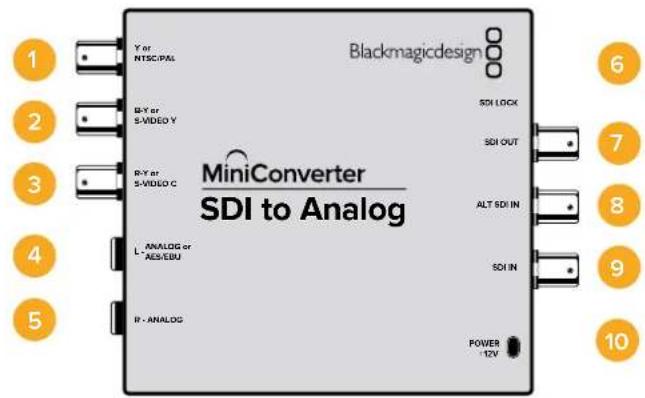
Pa3beMbl
Ynn NTSC/PAL
BNC-pa3bEm nla BbIbOda aHaNoROBOKOMnHOHTHO (Y) nn KOMnO3HTHO (NTSC/PAL) cnHaNoB.
2 B-Y nnS-VIDEO Y
BNC-pa3bem nIy BvBOda aHAnorOBOr KOmIOHeTHOrO (B-Y) cnHaJn S-Video (Y).
3 R-Y nn S-VIDEO C
BNC-pa3bem dIy BbIOda aHaIorOBoro KOMIOHEHTHO (R-Y) cHHaIa nn S-Video (C).
4 L-ANALOGnnnAES/EBU
Banachbni ananorobn (neBki KaH) nnn cnpoBoi AES/EBU-aynoBixOc pa3bemom 1/4 iouma.
5 R-ANALOG
BaanaHcHbI aHaIorOBbI ayINOBbIXoN (npaBbI kaHJI) c pa3beMOM 1/4 IIOHa.
6 NopT MINI-B USB
ObecneuBaet noKnIoueHne K Komblotepy c onepauonHOn cncTeMo Mac OS X nn Windows dny paobTo cytnnToB Blackmagic Converters Setup. TakaKe cnXnT nna 6OBHeHn BCTpoEHnO rO MmN-KOHBeptepa.
7SDIOUT
SDI-BbIXoC BNC-pa3beMOM
8 ALT SDI IN
DOnonHntenbHbSDI-BxOJnnyoBnoBaHnCnHaHa.
SDLIN
OCHOBHOI SDI-BXoA
10 POWER +12V
Bxod nntaHn 12 B.
Nepeknouatei
IpeeknouateB 8-Analog Audio, AES/EBU Audio
YctaHOBtne nepeKlHouateIb 8 B noLoXeHne OFF (BbIKI),yTObI bBbOdntb balaHcHbI aHaIorOBbl 3Byk, nll ON (BKn.) dny nCnOJIb3oBaHnna UnppOBOr AOES/EBU-BbxOda.
Ipeeknouateb7-7.5IRE,0.0IRE
B CUSA n ctpaHax, nCnONb3yOuNX CTAnDap NTSC (7.5 Setup), yCTaHOBtne nepeKIOUaTeNB 7 B noIooXeHne OFF (BbIKn.). B ctpaHax, He noNDEpKINBAIOUX NOoOBHb CTAnDapT, BB6epNTe IIOXeHne ON (BkI). 3Ta HacToPoiKa BnIeT ToIbKO Ha BbIXOdBi KOMIO3NTHOrO CnHana N S-Video.
Ipeeknouateb 6 - SMPTE Levels, Betacam Levels
Длг SMPTE yctahOBHTe nepeKlnquateB 6 B noLoXKeHne OFF (BbKn.),дг Betacam — B noLoXKeHne ON (Bkn.). HanboJee cacto ypoBeH cnHaIa yCTaHaBnBaETcNo CTaHdApTy SMPTE, pa60ty c kOTOpbIM nOJIepKxBaHOT MHorne yCTpOciTBA Betacam SP. HAcToPouKy dN Betacam SP cIeDyET bIbipatb IINb B TOM Clyuae, ecIn Bbl yBepHebl, YTO obOpydoBaHne icNoIb3ayet ypoBeHb Betacam.
Ipeeknouateb5-Componentnnn Composite/S-Video
YctaHOBtne nepeKIOUATEb 5 B noIOXeHne OFF (BbIKn.), YTObBi BBIOuNTb BVIOEO Ha aHaIIOBOBbI KOMNoHEHTb bIXoD. IINcNOb3OBAHHa KOMNo3HTHO BVIXoDa INS S-Video yCTaHOBtne nepeKIOUATEb B noIOXeHne ON (BKn.).
YTo6bBxOaHINHD-CnHAnNoCTyHnHa pa3bEm S-Video mN KOMno3HTBn BbxOD,Heo6xoDmO yctaHOBNTpepeKIOUaTeB noHIXaIOe KOHBePCnB nONoxHe N ON(BkI).JnKOMnoHETHORo aHAnorOBOro BNDeo NoDpeKnBaIoTc HNDSD.
IpeeknouateB 4 - SDl Audio De-Embed Bit 2
Ipeeknouatei 4,3 n 2 no3B0JIaOT nCIOB3OBAbT BOCEMb KOMHauCN ON/OFF.Cnx nMOuB MoXHO BbopaT BOCEMb pa3HbIX nap ayDnOKaHaNoB,KOTOpBle bdyT BbIeJeHbI N3 BXoJzero SDI-cirHana.
Ipeeknouateb 3 - SDl Audio De-Embed Bit 1
CM. onncahne nepekkuoateTn4.
IpeeknouateB 2 - SDl Audio De-Embed Blt O
CM. onncaHne nepeKIOUOaTeTn 4.
Ipeeknouateb 1- Processing Off/Processing On
Ipeeknoatele 1 no3Bolnret Bb6npatb nponopun Kaipa npn BblnoHeHH noHxauoae konBepcn n3 HD B SD. Hanpimep, npn KaKdoynctahOBKe nepeknouateB noLoxehne ON (Bk.) nCnoB3ayetcraOnn n3 trpx pex peKmOB: Anamorphic, Center Cut nn Letterbox. Pn noLoxehnn OFF (BbIK.) noHxaoaag KOnBepcn He BblnoHreTc, noToMy Ha BixOJ nocTynae HD-cuHaJ.
PnnoKIOUeHN K KOMNBIOTepy uepe3 nopT USB hActpoKaMn ynpabIaIOT c NOMOUIIOYtINITb Blackmagic Converters Setup. Ecn Heo6xOIMo coXpaHnTB bIbpaHHb peXm, OTcoEINHte KOHBepTe OT KOMNBIOTepa, OTKIOUHTe IN CHOBA BKLIOHTe NITaHne, a 3aTeM yCTaHOBITE NaCTPOIKNoHHkaIOSei KOHBpcuC n NOMOsbIO nepeKIOUcATE1.
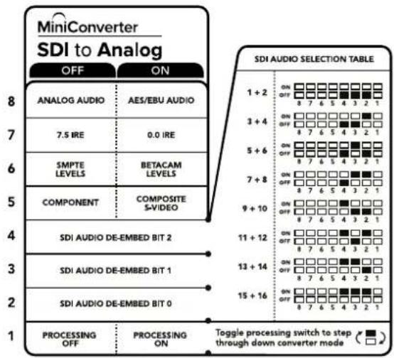
CxemaHaHnKHeN NOBepxHOCTNOKOpNyCa cOePxyT ONnCAHHe HAcTPOeK, COOTBeTCTByUOnx pa3HbIM NNoJKeHNrM NepeKnOuATEeNe
Ipnmep Hactpoek nepeekuoyatele
EcnHcOxMO BbIeCTn HD-BnDoe Ha KOMNHOHTbBbIXoN BblJeNTb ayIOKaHaJIb1n2
JnX BbBOda Ha aHaNoROBb BbIXoN, yctaHOBtnepeKIOuATEnn 8,5,4,3n2B noLoxeHne
OFF (BbIK).
AydnookaHaJIbSI-DcHana
| AydinoKaHaJIbI IpepekLIOuATEB 4 IpepekLIOUATeB 3 IpepekLIOUATeB 2 | Положени пеклочаюе пеклочаюе | ||
| 1и2 OFF OFF | ON OFF 8 7 6 5 4 3 2 1 | ||
| 3и4 OFF ON | ON OFF 8 7 6 5 4 3 2 1 | ||
| 5и6 OFF ON OFF | ON OFF 8 7 6 5 4 3 2 1 | ||
| 7и8 OFF ON ON | ON OFF 8 7 6 5 4 3 2 1 | ||
| 9и10 ON OFF OFF | ON OFF 8 7 6 5 4 3 2 1 | ||
| 11и12 ON OFF ON | ON OFF 8 7 6 5 4 3 2 1 | ||
| 13и14 ON ON OFF | ON OFF 8 7 6 5 4 3 2 1 | ||
| 15и16 ON ON ON | ON OFF 8 7 6 5 4 3 2 1 | ||
Hacrtpoyn ytnntbI Blackmagic Converters Setup
Ytuna Blackmagic Converters Setup no3B0n8e MeH8b HAcTpoK MmH-KOHBepTepa nOBHOBTb ero nporpamMHOe oecneueHHe.ДЯdoCTyNA K 3TNM HAcTpoKAM INCIOJIb3yIOT BknaK Video, Audio n About.
PaBota C BklaaKo About oncana B pa3dene «IImeHHeHne Hactpoek» daHnO pykoBDCTBa.
BklaKa Video dIa Mini Converter SDI to Analog daet BO3MOXHOCTb BbIpaTb ONICAHHbE HIXe onu.
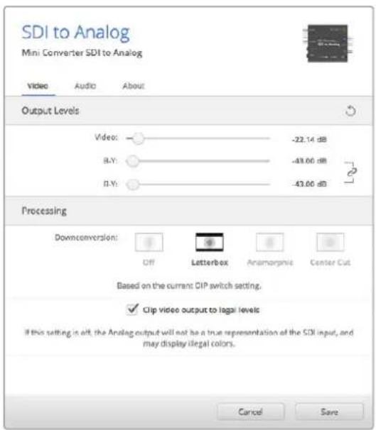
Bkna Video ytnbl Blackmagic Converters Setup no3bnyet yctaHOHTypoBNn ananoroboro BideocnHaN N b6paTb HactpOnn ppeo6pa0BaHn
MeHIO Processing
To MeHIO No3B0JIaET BbIbIpaTb IpONOpcN KaJaP Pa Pn BbINOnHeH N OHHaOJe KOnBepcN. MoJHO nCNoJIb3OBA Tb peKIMb Letterbox, Anamorphic, Center Cut nn Onuio OFF.
Onuia "Clip video output to legal levels" no3B0n8 aannpoabb BxoJaua SDI-cunHan dny BBOda uepe3 HDMi-INTepfec. No ymonuaHIO OHa doJxha 6bIt bKIOueHa.
MeHIO Output Levels
3TO MEHIO NO3BOJAEIT NO OTdJIbHOCTN yCTAHABINBAbYPOBEHB RPKOCTN/UBeTHOCTN,pa3HOCTB-YnR-Y.
Bknaika Audio nra Mini Converter SDI to Analog daet BO3MOXHOCTb Bbipatb oncaHHbe Hnke onu.
MeHIO Output Levels
3To MeHIO No3BOJIaET yCTaHaBbIbA bYpOBeHc rHaHa Ha ayDIOBbIXoHe. HAcTPOKmMOHO BbIpaTb InRA KaxdoRO KaHana NO OTdEnbHOCTn, a ecIn HaxaTB 3NaQOK cKpeKN cnpBa O cnaiepOB - nIra oboix cpa3y. TTo6bl BepHybCk 3HaueHHO O d5 nIra BCEx HAcTpoE, HaxMITE Ha 3NaQOK cbPocA B cTPOke Output Levels.

Bkndka Audio ytmntb Blackmagic Converters Setup no3B0nraT yctahOBt ypoBeHb aHaNoRoBOrO 3Byka
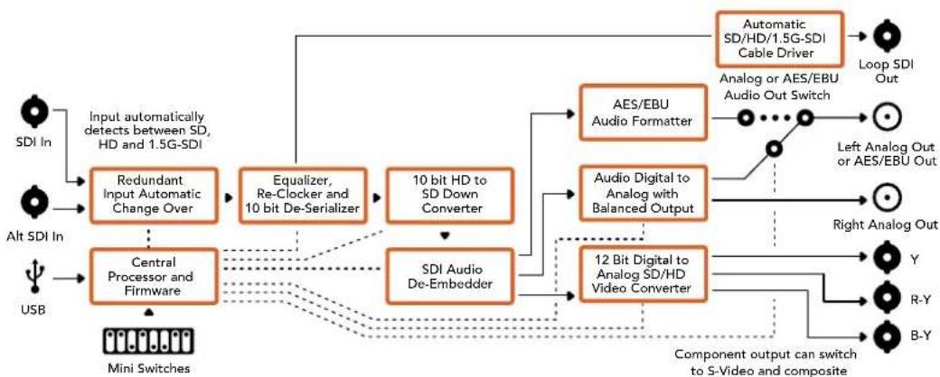
Cxema coeHneH Mini Converter SDI to Analog
Mini Converter SDI to Analog 4K
Modenb Mini Converter SDI to Analog 4K n ee MoDnFkaaSDI to Analog 4K Heavy Duty oBecneuBAIO TpeoobpaObaHne CnHaONoBD/HD/3G/6G-SDI B aHaIorOBoe KOMnoHeHTHOe BIneo, NTSC nIN PAL n BBIOOM 3ByKa Ha bAnHCbI AES/EBU- n aHaIorOBi BbIXoJ. IOnHKaOua KaHBePcHn Ha annapaTHOM yPoBHe No3BOJaTe nepeDaBaTb CnHaN BnNotb Do 6G-SDI Ha aHaIorOBoe SD- n HD-06OpdyoBaHne, B Tom YncNe Ha Betacam SP n VHSBnDeomarHHTofoHb. TaXKe MoXHo BbIeJIb Napbl ayDnOKaHNoB n3 16-KaHaJIbHorO 3ByKa, BCTpoEHoro B SDI-nOTok.
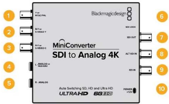
Pa3beMbl
1 Ynn NTSC/PAL
BNC-pa3bem IJIy BbIBOda aHaIOROBoro KOMIOHEHTHO (Y), KOMNO3HTHO CnHAIOB NNI NTSC/PAL.
2 B-Y uHnS-VIDEO Y
BNC-pa3bemДЯ BbIbOda aHAnorOBoro KOMNoHeTHHOro (B-Y) cHana nn S-Video (Y).
3 R-Y mnn S-VIDEO C
BNC-pa3bEmIЯ BbBOda aHaIorOBOro KOMnoHeTHHOrO (R-Y) cHrHaIa IIN S-Video (C).
4 L—ANALOG nnn AES/EBU
BaIaHcHbI aHaIIOroBbI (JIeBbI KaHaN) IINu cIpOBoA AES/EBU-aYdIOBbIXoC pa3bEmOM 1/4 IIOIMA.
5 R-ANALOG
Banachbni aHaNoROBb ayDnOBbIXoN (npaBbKaHaN) c pa3beMOM 1/4 JIOIma.
6 NopT MINI-B USB
ObecneuBaet noKnIoueHnK Komblotepy c onepauonHOnc nCTemOa Mac OS Xnn Windows dna paobToC cyTnInToB Blackmagic Converters Setup. TaKe cnXnT nnobHOBeHn BCTpoEHnro IIO MNHN-KOHBeptepa.
7 SDI OUT
SDI-BbXoNcBNC-pa3beMOM
8 ALT SDI IN
DOnonHntenbHybSDI-BxOJnpyoBpOBaHnCunHa.
9 SDIN
OCHOBHOI SDI-BXOJ.
10 POWER +12V
Bxod nHTaHn 12 B.
Pepekliouatei
COBET. Moelb Mini Converter Heavy Duty nMeet peaHOByKpbIuKy dna 3aunTbe nepeknouatee. TTo6bl nonuyntb docTyn K Hm, noHNMTe KpbIky.
Mini Converter SDI to Analog 4K Μeem πepekIoUaTei, c NOMOuI KOTOpbIX MOxHO BbIpaTb pa3nHbHe HactpoiKn pneo6pa3oBaHn.
IpeeknouateB 8-Analog Audio, AES/EBU Audio
YctaHOBtnepeKIOUATeIN8bnoJKeHHeOFF(BbIKn.)TTObblBOIDHTbAanHCbI anAnorOBbI 3Byk,nnON(BKn.)drrncnlo3oBaHnIuΦpOBoAES/EBU-BbIXoJa.
Ipeeknouateb7-7.5IRE,0.0IRE
B CIIA n ctpaHax, nCnONb3yIOuix CTaHdap NTSC (7.5 Setup), yCTaHOBtne nepeKlIOUaTeIb 7 B nOLOXeHne OFF (BbIK). B ctpaHax, He NODepKJBIAOUX NIOo6HbI CTaHdapT, BB6epNTe nOLOXeHne ON (BKn). 3Ta HAcTPOJka BnIureToNbKO Ha BbIXObl KOMNo3HTHO CrHana I S-Video.
IpekeKluOaTeNb 6 - SMPTE Levels, Betacam Levels
Дя SMPTE yctahOBHTe nepeKIOUaTeB 6 B noIoxKeHne OFF (BbKn.),ДЯ Betacam — B noIoxKeHne ON (Bkn.). HanboJe eacTo ypoBeH cInHa nA yctaHaBnBaTcra No cTaHdApTy SMPTE,paBoY c KOTOpbIM NOIDepKINBAOT MHOrne yCtpoiCTBa Betacam SP. HAcTPOkY dJa Betacam SP cIeDyET bIbupatb NIIb B TOM cIyae,ecn Bl yBepHebl, YTO obOpydoBaHne IcnoJIb3yET ypoBeH Betacam.
Ipeeknouateb 5 - Component nll Composite/S-Video
YctaHOBtne nepeKnOuateIb 5 B noLoXeHHe OFF (BbIKl.), YTObbl BbIOBntb BIneo Ha aHaIorOBbl KOMNoHEThbbl BixOd, IaNcNoJIb3ObaHHa KOMNo3HTHO BIXOda nn S-Video yCTaHOBtne nepeKnOuateIb B noLoXeHHe ON (Bkn).
YtobbXoJnHD-CunHan NoctynHa pa3bem S-Video nIIN KOMNo3HTbBbIXoB SDpa3peHnn, Heo6xOIMO yCTaHOBT nepeKIOUaTeNb noHnKaIoSei KOHBepCn B noIOnKeHNEON (BkI).ДЯ KMIOHENTHO anAHorO BINOEO NOIDepKINBaOTcH HD nSD.
Ipeeknouateb1 - Processing Off/Processing On
IpeeklouateIb 1 no3B0JraT BbIbpaT nponopznn KaJpa npn BblnoHHeHH noHNkaIOuei konBepcnn. Pnp KaJdoy yctahOBke peeklouateTn B noLoXeHne ON (Bkn.) nCnoNb3yETcra Odn H3 trpex peximob: Anamorphic, Center Cut nn Letterbox.
EcnHa BxOJ nocTynaeH D- nIuItra HD-cnHn, nIy BbIOa aHaIorOBoro HD-BnJeO Ha KOMNoHeHTbI BbXoYcTaHOBtne nepeKnIOUaTeB b noIOKeHne OFF (BbIKn.).
Дя понхаюшй коньерси Bxodяшero Ultra HD-cuhrana yctahobnte 3ot nepeknioчateNB noIOXeHne ON (BkI.) n BBiOpTe Heo6xoDnOoe noIOXeHne nepeknIOUaTeN5. PnBbIObeBnEO BΦopMaTe 4K DCI Ha komnoHeTHbI HD-BbIXoB bInOnJHraTc8 Ope3ka n3OpaXeHnA.
Длnoнжakошконьси BXOJUeRO HD-cuHana yctahOBnTe 3tOT nepeKIOUaTeIb B noLoXeHne ON (Bkn.) n bIbePnte Heo6xOdIMoe noLoXeHne nepeKIOUaTeIa5.
Pn noKnIOeHnn K KombIOTepy uepe3 npT USB hactpoKaMn ynpaBIAOT c NOMOuB yTNNTb Blackmagic Converters Setup. Ecn Heo6xOIMo coXpaHnTB BbIpaHHb pexm, OTCoeHNHTe KOHBepTe OT KOMlbIOTepa,OTKIOHTe n ChOBa BKIOHTe nTaHne, a 3aTEM yCTaHOBtE NaCTPOKN NOHxaIOe KOHBPcNN C NOMUbIO nepeKIOvate1.
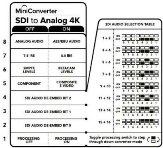
CxemaHaHnKHeNoBepxHocTN KOpnyca codepknT onnCaHne HAcTpoek, COOTBeTCTByIOux pa3HbIM noNOKeHNrMa nepeKnioateNei
Ppimep Hactpoek nepeekluoyatele
Ecn Heo6xmo BbBecn HD-buJeO Ha KOMnoHeHbB bixoN bIeNT ayIOkaHaIb1 n 2
DnX BBbOa Ha aHaNoRoBb BbIXoN, yCTaHOBtne nepeKIOUaTeNN 8,5,4,3 n 2 B noLoxeHne OFF (BblKn.).
Bb6op aydnocnHa
| Аudноаныпескюател 4 пескюател 3 пескюател 2 | Посожени пескюател | ||
| 1и2 OFF OFF | ON OFF 8 7 6 5 4 3 2 1 | ||
| 3и4 OFF ON | ON OFF 8 7 6 5 4 3 2 1 | ||
| 5и6 OFF ON OFF | ON OFF 8 7 6 5 4 3 2 1 | ||
| 7и8 OFF ON ON | ON OFF 8 7 6 5 4 3 2 1 | ||
| 9и10 ON OFF OFF | ON OFF 8 7 6 5 4 3 2 1 | ||
| 11и12 ON OFF ON | ON OFF 8 7 6 5 4 3 2 1 | ||
| 13и14 ON ON OFF | ON OFF 8 7 6 5 4 3 2 1 | ||
| 15и16 ON ON ON | ON OFF 8 7 6 5 4 3 2 1 | ||
Hacrtpoyn ytnnbl Blackmagic Converters Setup
Ytuna Blackmagic Converters Setup no3B0JET MeHb HAcTpoK MHH-KOHBePepa nOHOBnIb ero nporpAMHoe oecneHHe. DnA DOCTyna K 3TNM HAcTpoKam HcNoJIb3yIO T BknaKn Video, Audio n About.
Pa6Ota C BknaIkoJ About onncaHa B pa3dene «N3MeHHeHne HAcTpoE» DaHHoro pyKOBoCTBa.
Bknapka Video nra Mini Converter SDI to Analog 4K daet BO3MOXHocTb Bbipapb onncaHHbE Hnke OPIIN.
MeHIO Output Levels
To MeHIO NO3BOJAE T NO OTdEJIbHOCTN yCTaHaBnBaTb yPOBEH b RPKOCTN/CBETHOCTN, pa3HOCTb B-Y nR-Y.
MeHIO Processing
3To MeHIO No3BOJIeT BbIbpaTb nponopun KaIpa npi BbIIOHeHn NOnHxaOue KOBepcnn. MoXHO IcNoJIb3OBA Tb peKIMt Letterbox, Anamorphic, Center Cut nn Onuio OFF.
Onuia "Clip video output to legal levels" no3B0n8eT adanTnpoBaTB BXOJaSNI SDI-cnHAn dIy BbIOda uepe3 HDMI-INTepfnc. Iyo mOnuaHIO OHa doJnxHa 6bTy BKnIOueHa.
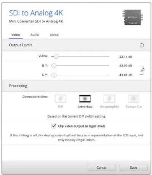
Bkna Video ytnnbl Blackmagic Converters Setup noBnreYcTaHOBnBt ypOBn aHaIorOBOr BndeocnHa n Bb6paTb HactpoN ppeoPazOBHn
BknaKa Audio dIa Mini Converter SDI to Analog 4K daet BO3MOXHOCTb BbIpaTb onicaHHbIe HIXe onu.
MeHIO Output Levels
3To MeHIO No3BOJnEYcTaHABINBaTb yPoBeHb CnHaHa Ha ayDnOBXoHe. HAcTpOKn MoXHO BvBpaTb Ia KaKDoI O KaHaI Na O TdEnbHOCTn, a cIe N HaxaTb 3HaUOK CKePENK nCpaba OT cnaIepoB - dIra oboix cpa3y. YToBb BepHyTbcR K 3HaueHIno O D5 dIra BCex HAcTpOeK, HaxMITE Ha 3HaUOK C6poca B cTpoke Output Levels.

Bknadka Audio ytnnbl Blackmagic Converters Setup no3BONaERYCTAHOBINyPOBEHb aHaIorOBOrO 3ByKa
Cxema coeHneHnn Mini Converter SDI to Analog 4K
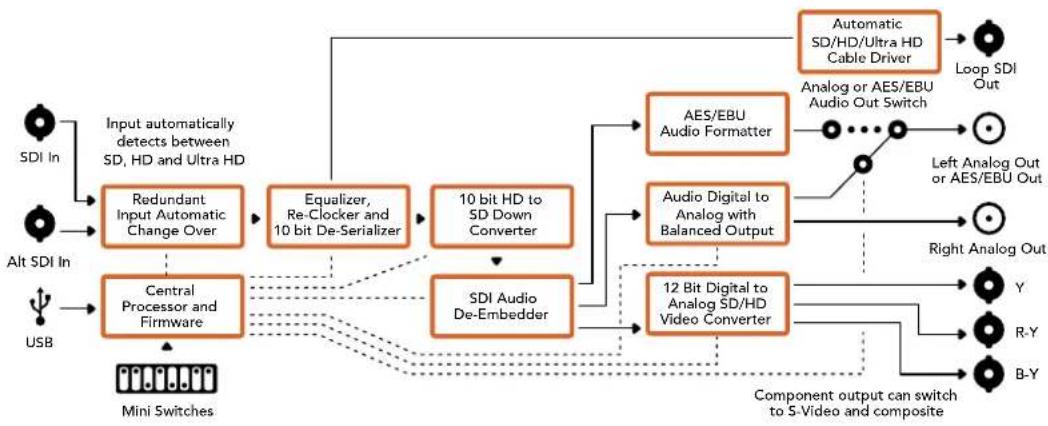
Mini Converter Analog to SDI
MoeB Mini Converter Analog to SDI n ee moDnFokaAn Analog to SDI Heavy Duty npoeobpa3yiot Bnuo n ayuio, noctynaoiue c ananoroboro oobpyobannra (hnapimep, Betacam SP, HDV- kamepbn irpoBbte npictabKn), B cnHnbl SD/HD-SDI. Ina ananorobbx n uippObix fopmatOB npedcmoTpehbl KOMnoHeHTbte pa3bembl SD/HN S-Video, Komno3ntbte BxoDb NTSC n PAL. HbXoax HD-SDI B cnHnAN MOxHO BCTpanBaTB zuPpOBoA AES/EBU- nn ananorobbl 3Byk.
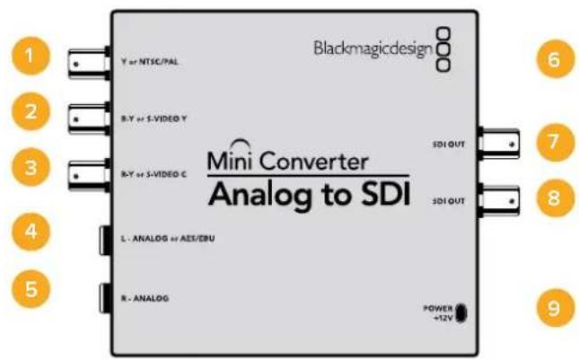
Pa3beMbl
1 Yunn NTSC/PAL
BNC-pa3bem nI BxOJaero aHaIorOBoro KOMNoEHTHO (Y) IIN KOMnO3HTHO crHana NTSC/PAL.
2 B-Y mnn S-VIDEO Y
BNC-pa3bem nIy BXOJaIero aHaNoROBOrO kOMnHOENTHOrO (B-Y) cnHana nn S-Video (Y).
3 R-Y mnn S-VIDEO C
BNC-pa3bem nIy BXoJrero aHaNoRorOBO rKOMnHOENTHO (R-Y) cHana nn S-Video (C).
4 L-ANALOGnnAES/EBU
Baanchb aHaIorOBb ayIOBxOJ (JIeBb KaH) nnu cnpoBoa ayIOBxOJ AES/EBU Cpa3bemom 1/4 Iouma.
5 R-ANALOG
Baanhchb h aHaIorOBb ayDIOBxO (npaBb KaH) c pa3beMOM 1/4 Iouma.
6 Nopt MINI-B USB
ObecneuBaet noKnHoueHnK Komblotepy c onepauonHoucntemOa Mac OS X nn Windows dny paobToC ytnInToB Blackmagic Converters Setup. TaKke cnxNt dn o6HOHeHn BCTpoEHnO rO MmH-KoHBeptepa.
7 SDI OUT
SDI-BbIXoC BNC-pa3beMOM.
8 SDI OUT
Btopoi SDI-BbIXoJ.
9 POWER +12V
BxOJ nHTaHn 12 B.
Ipeeknoyatei
COBET. Moenb Mini Converter Heavy Duty NMeet pe3HOByKpblkny dna 3auntb nepeknouatee. Yto6bI noynuHT doctyn K Hm, noHNMTe KpbkiKy.
Mini Converter Analog to SDI Μeet nepeKlouaTei, c nOmoUkoTOpbIX MOXHO BbUpaTb pa3nHbHe HactpoKn pneo6pa3oBaHna.
IpeeknouateB 8-Analog Audio, AES/EBU Audio
YctahOBtte nepeKnIOuateIb 8 nnoJxHne OFF (BbIKn.) yTO6b BbIpaTb 6aHaHCHb aHaIorOBbI 3Byk, nn ON (Bkn.) dnnncnO3oBaHna AES/EBU-BXoJa.
IpekeKIOUaTeNb 7-7.5 IRE,0.0IRE
B CUSA n ctpaHax, nCnoJIb3yIOUxN CTAnDAP T NTSC (7.5 Setup), yCTaHOBnTE nepeKIOuOATEIe 7 B noLOXeHne OFF (BbIK.). B cTpaHax, He noDnepKINBaIOUxN nooObHbI CTAnDAP (HaNPIMep, B IaONHn), Bb6epTe noLOXeHne ON (BKnI). 3Ta HAcTPOKa BInrE ToIbKO Ha BbIXObl KOMNo3HTHO rCirHana n S-Video.
Ipeeknouateb 6 - SMPTE Levels, Betacam Levels
3a Hactpoika no3B0nietncno3oBaTb DBe onu: SMPTE uH Betacam. dN a SMPTE yctahobite nepekniouateIb 6 B noLoKeHne OFF (Bbl)., nra Betacam - B noLoKeHne ON (Bkn.). Hanboonee qacto ypOBeH cInHana yCTaHabnBaetcna o CTanapTy SMPTE, paoTy cKOTOpbIM noepKBAOT MHOne yCTPOCTBa Betacam SP. Hactpoky dN Betacam SP cNeyET bBipatb nnB TOM Cnyae, ecn Bbl yBepenHb, YTO o6OpyDoBaHne nCNoJ3yeT yPObEH Betacam.
Переклочаль 5 - Componentи Composite/S-Video
YctaHOBtne nepeKIOUcATEb 5 B noIOXeHne OFF (BbIKn.) YTObBi BbIpaTb aHaIoroBbI KOMNoHEHTbI BxOJ. IJI BAIBopa KOMNo3HTHO BxOJa N S-Video yCTaHOBtne nepeKIOUcATEb B noIOXeHne ON (BKn.).
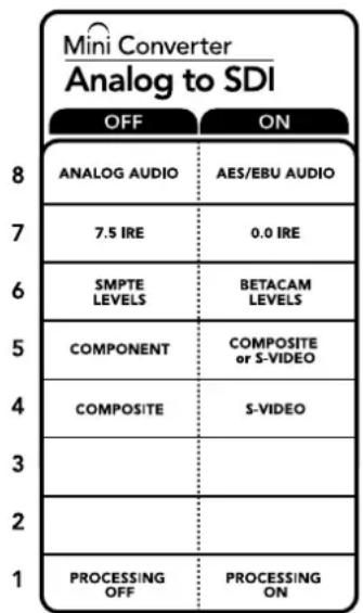
CxemaHaHnKHeNoBepxHocTKn Kopnyca codepknOncaHne Hactpoek,cooTBeTCTByIOuNX pa3hIMNOIOXeHNmpeekNIOUATEeNe
IpeeknouateB 4 - Composite, S-Video
YcTaHOBnTe nepeKnOuateNb 4 B noLoXeHne OFF (BbIK.) nIy BbIbopa KOMNo3nTHoro BnDeOBxOda. YTo6bl cInHaI noctynan Ha pa3bem S-Video, yCTaHOBnTe nepeKnOuateNb B noLoXeHne ON (BKn.).
IpeeknouateInb 1 - Processing Off/Processing On
TOT nepeeknouateIb He nCnonb3yETc.
Ppimep hactpoek nepeeklouatele
EcnHHeoBxOaIMOnCnOJIb30BaTbKOMNoHEHTbI BnDEOBXoD C aHaIIOROBbIM 3ByKOM, yCTaHOBtnepeKIOUcATEeN8 n5 bnoJoxKeHne OFF (BbIK).
Hac troponu ytniNbI Blackmagic Converters Setup
Ytnta Blackmagic Converters Setup no3B0nAeT MeHb HAcToPm MNH-KOHBepTepa nOboHbIb ero nporpamMHOe oecneueHHe. DnA DocTyNA K 3TNM HAcToPmKAM NcNoIb3yIOB BklaKn Video, Audio n About.
Pabota c Bklaikoi About onncaHa B pa3dene «N3MeHeHne HacTpoeK» daHHoro pykoBODCTBa.
Bknadka Video dnia Mini Converter Analog to SDI daet Bo3moKHOCTb Bbl6paTb onncaHHhe Hnke onu.
Meho Input Levels
3TO MEHIO N03BOJRAET NO OTdJIbHOCTN yCTaHaBnBaTb yPOBeHB rPKOCTN/UBeTHOCTN,pa3HOCTb B-Y nR-Y.
Bknadka Audio nra Mini Converter Analog to SDI daet BO3MOXHocb BblpaTb onncaHHbIe Hnke onu.
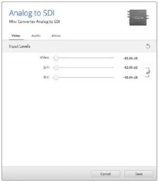
Bkna Video ynnnbl Blackmagic Converters Setup no3BONaTeYcTaHOBnTyPOBnBnDeoCnHa
Meho Input Levels
3TO MEHIO NOBONET yCTaHABINBaTb yPOBeHcHana Ha ayDnOBxOJe. HAcTpOKn MoXHO BbpaT dIy KAKDOrO KaHana N O TdEJIbHOCTN, a eCNI HAKATb 3HaUOK cKpeKN CnpaBA OT cNaIepOB -Ig OBouxCpABy. YTo6bl BepHyTbcra K 3HaueHIO O D5 dIra BCex HAcTpOeK, HaxMITE Ha 3HaUOK c6poca B cTpoke Input Levels.
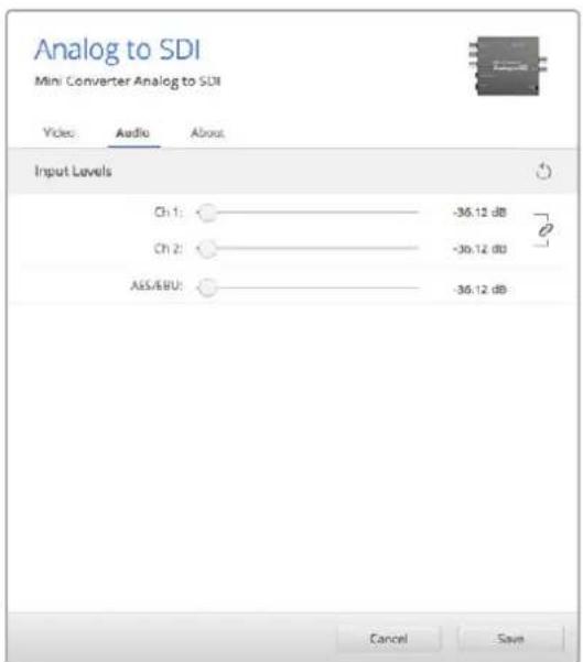
Bknadka Audio ytmntbl Blackmagic Converters Setup no3B0nraet yctahOBHTyPOBeHb aHaNoRoBOrO 3ByKa
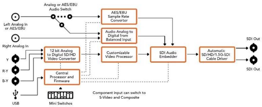
Cxema coeHneH Mini Converter Analog to SDI
Mini Converter SDI to Audio
Modenb Mini Converter SDI to Audio no3B0n8e BbDn8t bHeBpe KaHana 3Byka n3 IIOBOrO SDI-cnHana n BbBODHT ero KaK HeTpe KaHana aHaIoroBOrO nn BOCemb KaHanoB uΦpOBoro AES/EBU-BbXoJa. KOHBPert dOnyckaet BbBOd 3Byka Ha TaKoe ayDnOooBOpydoBaHne, KaMKsepb, aHaIoroBBte DeKN KcHTpOblbHe MOHToPb. IaN BbDeneHn 3SDI-noToKa DOnONHtEnbHix KaHAnOB 3Byka MoKHO mCNoB3ObaT eEe OOnH MmH-KOHBPert SDl to Audio, NOkKnoueHHbIK SDI-BbIXoY c NOMoBtu NocLeDoBATEhBOr CoeINHeHH.
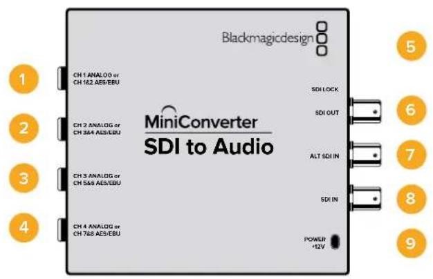
Pa3beMbl
1 CH 1 ANALOG nIu CH 1 & 2 AES/EBU
BaHCHbI aHaIorOBbI (KaHbI 1) nnuΦpOBoA AES/EBU-BbIXoD (KaHaIbI 1n2) cpa3bEmOM 1/4 dIOma.
2 CH 2 ANALOG nnn CH 3 & 4 AES/EBU
BaHaHcHb aHaIorOBbI (KaHb 2) nIIu cIuΦpOBoAES/EBU-BbIXoI (KaHaJIb3n4) Cpa3bEmOM 1/4 IIOIma.
3 CH 3 ANALOG nnn CH 5 & 6 AES/EBU
BaIaHcHbI aHaIorOBbI (KaHbI 3) mIu cIuΦpOBoA EAS/EBU-BbIXoD (KaHaJIbI 5 n 6) Cpa3bEmOM 1/4 IouMa.
4 CH 4 ANALOG nnn CH 7 & 8 AES/EBU
BaHCHbI aHaIorOBbI (KaHb 4) nIe IuΦpOBoA EAS/EBU-BbIXoN (KaHaJIb7n8) Cpa3bEmOM 1/4 JIOJMa.
5 NopT MINI-B USB
ObecneuBaet noKnHoueHnK Komblotepy c onepauonHOn ciTeMoM Mac OS X nn Windows dny paobTy cyTnHToB Blackmagic Converters Setup. TaKke cnYknt dnna 6bHOHeHH BCTpoEHnO rMO mHN-KoHBeprepa.
6 SDI OUT
CKBO3HOI SDI-BbIXOc BNC-pa3beMOM.
7 ALT SDI IN
DOnonHnteBnBbSDI-BxOaIy6bnpoBaHnCnHa. Pn noKnIOueHN nCTouHnKOB K oobm BxOaAM, SDIN ALT SDIN, BtOpo n3 Hx Byet nCnoB3oBaTbc npn pponadaHn CnHana Ha OCHOBHom. Bcnyae nepexoHa ha paobTy cdoonHnteBbIM SDI-BXoOM HaHnHaet MraTb HnNkatop SDI LOCK.
8 SDIN
OCHOBHON SDI-BXoA.
9 POWER +12V
Bxod nntaHn 12 B.
IpeeknIOuataeI
Mini Converter SDI to Audio nmeet nepeknouatei, c nomooukoTOpbIX MOxHO BbipapTa pa3nuehhe HactpoKn pneo6pa3oBaHna.
IpeeknouateB 8-Analog Audio, AES/EBU Audio
YctahOBITE nepeKIOUaTeIb 8 b noJoxeHne OFF (BbIKI), yTObblbOuNTb banaHCbI aHaONOBII 3Byk, nI ON (BKn.) dIy nCnOJIb3oBaHnI cIΦpOBOr AOES/EBU-BbxOJa.
IpeeknouateNB 6-Audio Group Bit 1
Ipeekioateen 6 n5 no3BolnoiOT nCnObn3oBaTb yteblpe KOMbHaun ON/OFF. 3To daet BO3MOxHOCTb BldeJIbN 13 BXOJaUero SDI-notoka anHAnorOBb 3Byk (yTeblpe Habopa no Yteblpe KaHana KaKdb) nn AES/EBU-3Byk (Dba Habopa no BOCMb KaHanoB).
Ipeeknioateb5-AudloGroupBit0
CM. onncaHne npeekuOateTn6
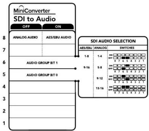
Cxema Ha HnKHei NobepxHocn Kopnyca
Copepknt OncacHne HAcTpoek, COOTBcTeCTByIOxN X
pa3HbIM NIOXeHNrM npeKnOuTeNei
Ppimep hactpoek nepeekluoyatele
EcnHcO6xOIMOBbIpaTbaynOKaHaJIbICnepBOroNoYeTBepTbI,yCTaHOBNTepeKJIOUaTeJI 8,6n5BnoJoxHeNE OFF(BbIK).
Bb6op aydnocnHa
| Аналоговы щадиоканны | Пeреκлючател 6 | Пeреκлючател 5 | Положенияпeреκлючател |
| 1-4 OFF OFF | ON OFF 8 7 6 5 4 3 2 1 | ||
| 5-8 OFF ON | ON OFF 8 7 6 5 4 3 2 1 | ||
| 9-12 ON OFF | ON OFF 8 7 6 5 4 3 2 1 | ||
| 13-16 ON ON | ON OFF 8 7 6 5 4 3 2 1 | ||
| Каданы AES/EBU-Звуka | Пeреκлючател 6 | Пeреκлючател 5 | Положенияпeреκлючател |
| 1-8 OFF OFF | ON OFF 8 7 6 5 4 3 2 1 | ||
| 9-16 OFF ON | ON OFF 8 7 6 5 4 3 2 1 |
HactpoynuYtntbI Blackmagic Converters Setup
Ytuna Blackmagic Converters Setup no3B0n8e MeH8b HAcTpoK MHH-KOHBePepa nOHOBn8 ero nporpaMMHoe oecneueHHe. Dna DocTyNA K 3TNM HAcTpoKAM NcNoJIb3yIOT BkJaKn Audio n About.
Pabota Cbklaikoi About onicaHa B pa3dene «N3meHHe HAcTpoek» daHHoro pykoBocTba.
BknaJaA Audio nla Mini Converter SDI to Audio daet Bo3moXHocTb Bbipatb onncAHhie Hnke onu.
MeHIO Output Levels
3TO MeHIO NoBONReT yTaHaBnBAtb yPoBeHc CnHaHa ayDnOBbXOe. HAcToPmKOxHO BbpaT dI KKaJdOro KaHana I O TdEJIbHOCTn, a cIIN HaKaTb 3HaQOK cKpeKN cnpBa OT cIaIepOB -I I Na nap KaHAnOB. YTo6bl BepHyTBcR K 3HaueHInO O d5 dnn BCex HAcTpoEK, HaxMITE Ha 3HaQOK c6poca B cTPOke Output Levels.

BknaAudi ynnnbl Blackmagic Converters Setup no3BONReTycTaHOBnTByPOeHB 3Byka

Cxema coeHneH Mini Converter SDI to Audio
Mini Converter SDI to Audio 4K
MoJIb Mini Converter SDI to Audio 4K no3BONJET bIDeJIbYtBpe KaHana 3Byka n3 IIOBOrSDI-cnHana n BbIOJITb ero kak Yteblpe kaHana aHaIOROBOro nn BOCEm b KaHANOB uDpOBOrAES/EBU-BbIXOA. KOHBePep dOnyckaet BbIOd 3Byka Ha taKoe ayDnOooBpyoBaHne, KaMKWepb, aHAnorOBble DeKN i KOnTpObnble MOHTOpbl. DnA BbIeNeHnN 3 SDI-noToKadoNoHNTeNbBx KaHANOB 3Byka MoXHO NcNoIb3ObaTbe eJe Odn H MInH-KOHBePep SDI to Audio4K, noKnIOueHHnK SDI-BbIXOyC NOMOuBIO NOceIoBATEnbHOcoEINHeHn.
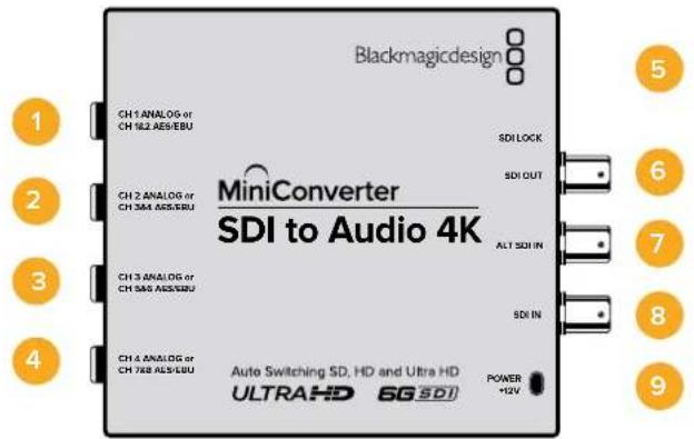
Pa3beMbl
1 CH 1 ANALOG nIu CH 1 & 2 AES/EBU
BaHaHcHbAHaNoRObBn(KaHb1)nnuΦpOBoAES/EBU-BbIXoD(KaHaNb1n2)cpa3bEmOM 1/4dIOIma.
2 CH 2 ANALOG nnn CH 3 & 4 AES/EBU
BaHaHcHb aHaIorOBbI (KaHb 2) nIIu cIuΦpOBoAES/EBU-BbIXoI (KaHaJIb3n4) Cpa3bEmOM 1/4 IIOIma.
3 CH 3 ANALOG nnn CH 5 & 6 AES/EBU
BaIaHcHbI aHaIorOBbI (KaHbI 3) mIu cIuΦpOBoA EAS/EBU-BbIXoD (KaHaJIbI 5 n 6) Cpa3bEmOM 1/4 IouMa.
4 CH 4 ANALOG nnn CH 7 & 8 AES/EBU
BaHCHbI aHaIorOBbI (KaHb 4) nIe IuΦpOBoA EAS/EBU-BbIXoN (KaHaJIb7n8) Cpa3bEmOM 1/4 JIOJMa.
5 NopT MINI-B USB
ObecneuBaet noKnHoueHnK Komblotepy c onepauonHOn ciTeMoM Mac OS X nn Windows dny paobTy cyTnHToB Blackmagic Converters Setup. TaKke cnYknt dnna 6bHOHeHH BCTpoEHnO rMO mHN-KoHBeprepa.
6 SDI OUT
CKBO3HOI SDI-BbIXOc BNC-pa3beMOM.
7 ALT SDI IN
DOnonHnteBnBI SDI-BxOd nIy6bnpoBaHnCnHa. PpN NOkIoueHn NCTouHKnOB K oboim BxOaM, SDIN ALT SDIN, BtOpoi n3 Hx Byet nCNoB3oBaTbc npi nponaadHn CnHana Ha OCHOBHom. B cnyae nepexoHa ha paobTy c DononHnteBhIM SDI-BXODOM HAHHaET MIRATb INHdkatop SDI LOCK.
8 SDIN
OCHOBHON SDI-BXoA.
9 POWER +12V
Bxod nntaHn 12 B.
Ipeeknloatei
Mini Converter SDI to Audio 4K Imeet nepekkuateen, c nmoou KOtOpbIX MOxHO BbupaTa pa3nHHe HactpOuN pneo6pa3OBAHna.
IpeeknouateB 8-Analog Audio, AES/EBU Audio
YctahOBITE nepeKIOUaTeIb 8 b noJoxeHne OFF (BbIKI), yTObblbOuNTb banaHCbI aHaONoBbI 3Byk, nI ON (BKn.) dIy IcnoJIb3ObaHnI cIΦpOBOr AOES/EBU-BbxOJa.
IpeeknouateNB 6-Audio Group Bit 1
Ipeekioateen 6 n 5 no3BolnoiOT nCnObn3oBaTb chebipe KOMbHaun ON/OFF. 3To daet BO3MOxHOCTb BldeJIb n3 BXOJaUero SDI-notoka ananorOBbl 3Byk (chebipe habopa no chebipe KaHana kackdy) nn AES/EBU-3Byk (Dba habopa no BOCMb KaHanoB).
Ipeeknioateb5-AudloGroupBit0
CM. onncaHne nepeeknouateJ6
Ppimep Hactpoek nepeknoatele
EcnHno6xOIMO BbIpaTb ayDnOKaHaIbI C nepBOro nO ueTbeptbI, yCTaHOBtne nepeKIOuATeTI 8,6 n5B noIoXKeHHe OFF (BbIK).
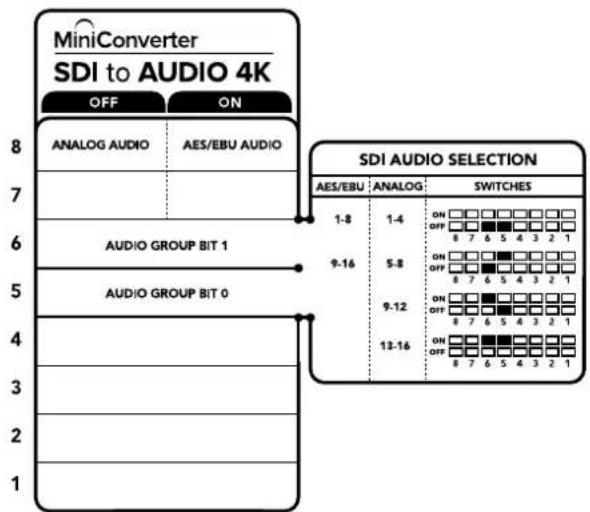
CxemaHaHnKHeNoBepXHOcN KOpNyCa cOePknT OnncAHne HAcTpoE,coOTBeTCTByIOx pa3HbIM nIOJKeHHm NpeeknoyateNei
Bb6op aydnocnHa
| Аналоговы щадиоканны | Пeреκлючател 6 | Пeреκлючател 5 | Положенияпeреκлючател |
| 1-4 OFF OFF | ON OFF 8 7 6 5 4 3 2 1 | ||
| 5-8 OFF ON | ON OFF 8 7 6 5 4 3 2 1 | ||
| 9-12 ON OFF | ON OFF 8 7 6 5 4 3 2 1 | ||
| 13-16 ON ON | ON OFF 8 7 6 5 4 3 2 1 | ||
| Каналы AES/EBU-Звуka | Пeреκлючател 6 | Пeреκлючател 5 | Положенияпeреκлючател |
| 1-8 OFF OFF | ON OFF 8 7 6 5 4 3 2 1 | ||
| 9-16 OFF ON | ON OFF 8 7 6 5 4 3 2 1 |
Hac troponu ytnntbI Blackmagic Converters Setup
Ytuna Blackmagic Converters Setup no3BnIeT MeHb HAcTpOKn MHH-KOHBePepa nOBnBnIb ero nporpaMMHoe oecneueHne.ДЯdoCTyna K 3TNM HAcTpOKnMnONlb3yIOT BklaKn Audio n About.
Pabota C BklaKoB About onicaH a pa3dene IImeHeHHe HAcTpoek DaHORO pyKOBOCTBa.
BklaKa Audio nra Mini Converter SDI to Audio 4K daet BoaMOxHocTb Bb6paTb onicaHHbE HnKe onu.
MeHIO Output Levels
3TO MeHIO No3BOJAEYcTaHaBnBaTb yPoBeHc CnHaHa ayDnOBxOe. HAcToPmKOxHO BbpaT dIa KaJdOrO KaHana N O TdEJIbHOCTN, a cIIN HaKaTb 3HaUOK cKpeKN cnpBaOT cIainepoB -I Ia nap KaHAnOB. YTo6bl BepHyTBcR K 3HaueHInO O D5 dIra BCex HAcTpoEK, HaxMITE Ha 3HaUOK c6poca B cTPOke Output Levels.

BknaAudi ytnnbl Blackmagic Converters Setup no8oanrteyctahOBt ypoBHe h aHaior oBOrO 3Byka
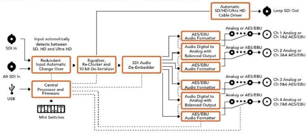
Cxema coeHneH Mini Converter SDI to Audio 4K
Mini Converter Audio to SDI
MoeB Mini Converter Audio to SDI no3B0JAE BCTpaBaT yeIbe KaHana aHaIorOBoro nIb BOCemb kaHANOB cIpPBOrO AES/EBU-aynO B IIO6oBDI-CIRHan. 3To Daet BO3MOXHOCTb BKIOuATb B SDI-cirHan 3ByK, noIyehHHc MmKwepa H aHaIOROBo DEKN, npepaBaT b erO Ha SDI-KOMMyTaOpbl NDeKN. JnB BCTpaBaHHa B SDI-NOTOK dONONHTeNbHX KaHAnOB MOxHO nCNoB3OBaTB eOE OIN MHN-KOHBeTpEap Audio to SDl, noKnIOueHHbIK SDI-BbIXOy C NOMOsbIO nocJeDoBAteBHorO CoEINHeHra.
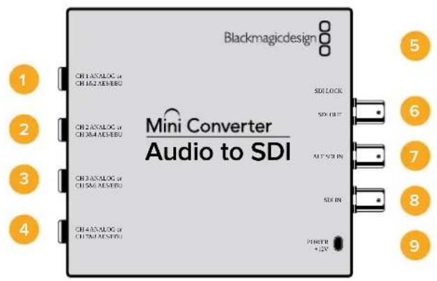
Pa3beMbl
1 CH 1 ANALOG nnn CH 1 & 2 AES/EBU
BaanchbnaHOrOBbI (KaHb1) nHn cHpOBoA EAS/EBU-BXoD (KaHaBb 1n2) Cpa3bemom 1/4 IIOma.
2 CH 2 ANALOG nIN CH 3 & 4 AES/EBU
BaIaHcHbI aHaIorOBbI (KaHbI 2) mIu cIePpOBoA EAS/EBU-BXoD (KaHaJIb3n4) Cpa3beMOM1/4IOJMa.
3 CH 3 ANALOG nn CH 5 & 6 AES/EBU
BanaHcHbA hAnorObBn (KaHaI 3) nIn uNpOBoA AES/EBU-BxOJ (KaHaJIb5n6) Cpa3bEmOM 1/4 IIOIma.
4 CH 4 ANALOG nHn CH 7 & 8 AES/EBU
BaHaHcHb aHaIorOBbI (KaHaI 4) nIu cHpOBoAES/EBU-BXoD (KaHaJIb7n8) Cpa3bEmOM 1/4 IIOMa.
5 Nopr MINI-B USB
ObecneuBaet noKnHoueHnK Komblotepy c onepauonHOn ciTeMoM Mac OS X nn Windows dny paobTy cyTnHToB Blackmagic Converters Setup. TaKke cnYknt dnna 6bHOHeHH BCTpoEHnO rMO mHN-KoHBeprepa.
6 SDI OUT
CKB03Hoi SDI-BbIXoD c BNC-pa3beMOM.
7 ALT SDI IN
DOnonHnteBnBbSDI-BxOaIyDy6nnpoBaHnCnHaI. Ppi NoKIOUeHN NCTouHKnOB K oobm BxOaAM, SDIN ALT SDIN, BtOpoi n3 Hx Byet nCnoB3OBaTbCp nponaadHn CnHana Ha OCHOBHom. Bcnyae nepexoHa paBoTy c DonoHnteBbIM SDI-BxOaOM HaunHaet MraTb HndkaTop SDI LOCK.
8 SDIN
OCHOBHON SDI-BXoA
9 POWER +12V
Bxod nntaHn 12 B.
Ipeeknloatei
Mini Converter Audio to SDI nmeet nepeknoyatei, c nmoosbIO KOtopbIX MOxHO BbOpaTb pa3nHbHe HactpOKn pneo6pa3OBAHn.
IpeeknouateB 8-Analog Audio, AES/EBU Audio
YctahOBtte nepeKIOUaTeB 8 nnoXeHne OFF (BbIKn.), TTObI BbIpaTb 6aHaHcHbI aHaIorOBbI 3Byk, nn ON (BKn.) drrncnoB3oBaHna AES/EBU-BxoJa.
Ipeeknouateb7-Sample Rate Conversion, No Sample Rate Conversion
UctahOBtte nepeKIOuateIb 7 B noLoXeHne OFF (BbIKn), UTObI bInonHrtb npeoob3ObaHne
HaCTOtbl dNcKpeTn3aun, INB NOLOXeHne ON (BKn), UTObI He NcNoJIb3OBA Tb 3Ty OINIO.
IpeKIOuateIb noTuB CERda DOnJxH HaxOITbcB NOLOXeHn OFF (BbIKn), UTObI
BCTpaBaembl ayDnOCnHaI IMeJ YnCKpeTn3aun TeJeBn3NOHHoro CTaHdApTa.
Ecnne nepeknioquatienb 7 haxoHntcB noLoxhenn OFF (BbKn.), SDI-cunHan Ha BbxOe 6ydet nmetb BCTpoehnbl aHaNoRoBbl nn AES/EBU-3Byk c qactotoi dNckpeTn3aunn 48 kFt. KOrda nepeknioquatienb 7 yctaHOBneB noLoxhenne ON (BKn.), aydno BbIOHTcC taKo Jx qactotoi DnckpeTn3aunn, kaH bXoJe.
Ipeeknouateb6-Audio Group Bit 1
Ipeeknioateenn 6 n5 no3BnonIO nCnoNb3oBaTb yetbipe KOM6Haun ON/OFF. 3to daert B03MOXHOCTB BCTpaNBtB SDI-cuHn Ha BbIXOe do Yetbipex KaHAnOB aHaIorOBoro nn Do BOCBMn KaHANOB uHΦpOBOr AOES/EBU-3Byka.
Ipeeknioateb5-AudloGroupBit0
CM. onncaHne nepeKIOUOaTeTn6.
Bb6op aydnocnHa
| Аналоговы щадиоканны | Переклочател 6 | Переклочател 5 | Положения переклочател |
| 1-4 OFF OFF | ON OFF 8 7 6 5 4 3 2 1 | ||
| 5-8 OFF ON | ON OFF 8 7 6 5 4 3 2 1 | ||
| 9-12 ON OFF | ON OFF 8 7 6 5 4 3 2 1 | ||
| 13-16 ON ON | ON OFF 8 7 6 5 4 3 2 1 | ||
| Кааны AES/EBU-3byka | Пeреknючател 6 | Пeреknючател 5 | Положения пeреknючател |
| 1-8 OFF OFF | ON OFF 8 7 6 5 4 3 2 1 | ||
| 9-16 OFF ON | ON OFF 8 7 6 5 4 3 2 1 |
BctpaunBaHne nnn BbIeJeHne 3Byka
Pocne BbIbopa aydnokaHANOB nCnObl3yIte nepeKIOUaTeEN 4,3,21,HTo6bHa3HaHTb KaHAlbl dIraBcTpaNBAHIN nn OTKnIOuHTb nx. OTKIOUeHHe no3BOJrE n36ExaTb 3aIncn Ha tex 3ByKObIX kaHAnax, KOTOpBie Heo6xOIMO coXpaHITb B SDI-CnHane.
Haep,ecnnyknoOTKnIOuHTb aHanoRObI ayNOKaHb1 nKanBa1 2 AES/EBU-3yka, yctahOBte nepeKIOUaTeIb 1B noJoxHe N (Bkn.).Korda nepeKIOUaTeIb 1 HaxoNTcB B noJoxEHn OFF (BbKn.),ayNOKaHbI bdyT BCTpoEhbl CnHAn.
HactpoynIyBbIeIeHnI OTKJIoueHnI ayDnOKaHaIOB
| Переклочателов Нстroduка Адноюнalsi | |
| 4 | ON OTКLOчение кана 4 (аналоговий 3byk), kahandов 7-8 (AES/EBU) |
| OFF Bстroduвашие кана 4 (аналоговий 3byk), kahandов 7-8 (AES/EBU) | |
| 3 | ON OTKLOчение кана 3 (аналоговий 3byk), kahandов 5-6 (AES/EBU) |
| OFF Bстroduвашие кана 3 (аналоговий 3byk), kahandов 5-6 (AES/EBU) | |
| 2 | ON OTKLOчение кана 2 (аналоговий 3byk), kahandов 3-4 (AES/EBU) |
| OFF Bстroduвашие кана 2 (аналоговий 3byk), kahandов 3-4 (AES/EBU) | |
| 1 | ON OTKLOчение кана 1 (аналоговий 3byk), kahandов 1-2 (AES/EBU) |
| OFF Bстroduвашие кана 1 (аналоговий 3byk), kahandов 1-2 (AES/EBU) | |
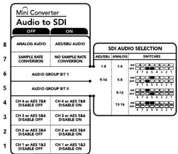
CxemaHa HnKHeH NOBepxHOCT KOpnyca copepXHT OnncAHHe HAcTpoek, COOTBeCTByOuNX pa3HbIM NOnOKeHnM nepeKnOHTeNei
Ipnmep Hactpoek nepeekuoyatele
EcnHcO6xOaIMo Bb6paTb ayDnOKaHaIbI C nepBOrO no YcTeBepTbI, yCTaHOBtne nepeKIOuAteJI 8,6n5BnoJoxHeNHE OFF (BblKn.).
Hac trokn ytnntbl Blackmagic Converters Setup
Ytuna Blackmagic Converters Setup noaBnaret MeHb HacpoKN MHH-KOBepTepa nOHOBnIb ero nporpamMHOe oecneHHe.ДЯdoCTyNA K ATIM HAcToKAM NcNoJIb3yOT BkJaKn Audio n About.
Pa60Ta C BknaKoI About onncana B pa3dene «I3MeHHe HacTpoE» DaHHoro pykoBocTba. BknaKa Audio nra Mini Converter Audio to SDI daer Bo3moXHoCTb Bbipatb onncAHbte Hnke onu.
Meio Input Levels
3To MeHIO No3BOJAEYcTaHaBnBaTb yPoBeHb CnHaHa ayDnOBxOJe.HAcTpoK MoKHO BbOpAe DnI KKaDDo KaHAna N0 OTdEJIbHOCTN, a cCIN HaKaTb 3HaQOK CKePENK CNpaBA O T cnaIepoB —dIy nap KaHAnob. YTo6bl BepHyTBcR K 3HaueHInO O d5 dnn BCex HAcTpoE, HaxMITE Ha 3HaUOK c6poca B cTPOke Output Levels.
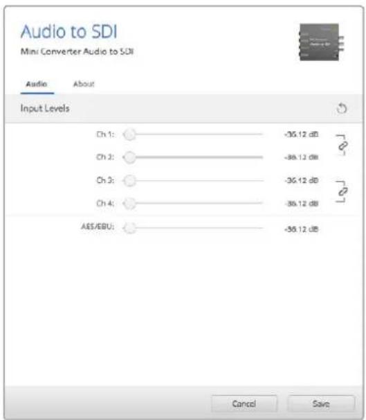
BknaKa Audio ynnnbl Blackmagic Converters Setup noBnonyctaHOHTb ypoBeH aHaororOro 3Byka
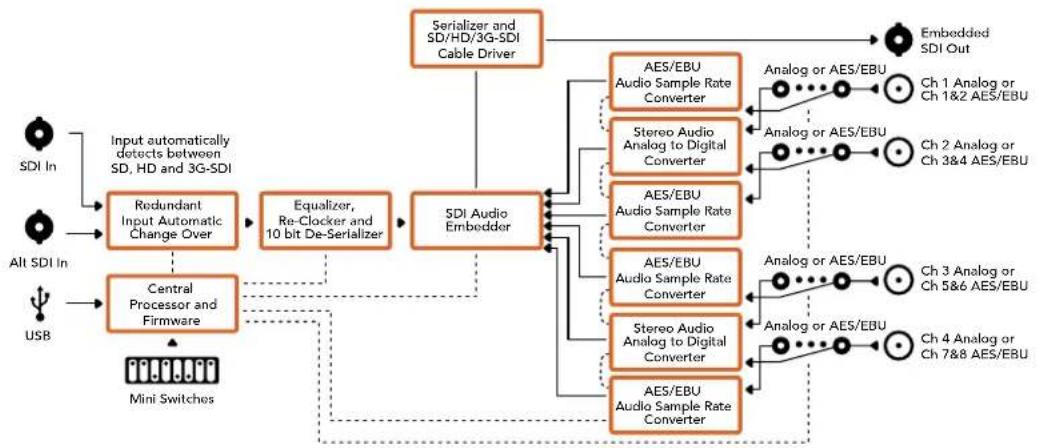
Cxema coeHneH Mini Converter Audio to SDI
Mini Converter Audio to SDI 4K
Modenb Mini Converter Audio to SDI 4K no3BONaET BCTPANBaT bYeTbpe KaHana aHaIorOBoro nn BOCemb KaHANO B cHpOBO AES/EBU-aynO B IIOoB SDI-cnrHan. 3TO DaET Bo3MOXHOCTb BKIOuATb B SDI-notOK 3Byk, nOlyueHHb C MmKwepa N aHaIorOB O dKeN, n nepeDaBaT b erO Ha SDI-KOMMyTaTOPbI N dKeN. DnB BCTPANBaHn DOONHHTeNbHX KaHAnOB MOxHO NcNoB3OBaT b eue Odn MNHN-KOHBeTpAudi to SDI 4K, nOdknIOueHHb K SDI-BbIXOy C NOMOsbIO nocJeDoBaTeNBHO coeINHeHra.
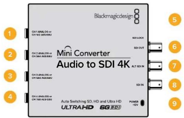
Pa3beMbl
1 CH 1 ANALOG nHn CH 1 & 2 AES/EBU
Baanchb aHaonobb (KaHb1) nIu npoBoAES/EBU-BxOa (KaHb1n2) cpa3bemom 1/4 duim.
2 CH 2 ANALOG nnn CH 3 & 4 AES/EBU
BaHaHcHb aHaIorOBbI (KaHaI 2) nIu cIePpOBoAES/EBU-BXoD (KaHaIb3n4) Cpa3BeMoM 1/4 IIOMa.
3 CH 3 ANALOG nn CH 5 & 6 AES/EBU
BaIaHcHb aHaIorObB (kaHb 3) nIu cIePpOBoA EAS/EBU-BxOd (kaHaJIb 5n6) Cpa3beMOM 1/4 IIOIma.
CH4ANALOGnnnCH7&8AES/EBU
BaHCHbI aHaIorOBbI (KaHAI 4) IIN UΦpOBoA EAS/EBU-BXoI (KaHaJIb7n8) Cpa3bEmOM 1/4 JIOIma.
5 Nopr MINI-B USB
ObecneuBaet noKnIoueHne K Komblotepy c onepauonHou cnCTemOa Mac OS X nn Windows dna paobt cyntnToB Blackmagic Converters Setup. TaKke cnjxnt dnna 6OBHeHb BCTpoEHHO rMO MNH-KOHBeptepa.
6SDIOUT
CKBO3HON SDI-BbIXOc BNC-pa3bEmOM.
7 ALT SDI IN
DOnonHnteBnBbSDI-BxOaIyDy6nnpoBaHnCnHa. PpN noKnIOueHHN nCTouHnKOB K oboM BxOaAM, SDIN ALT SDIN, BtOpO h3 Hx Byet nCnoB3oBaTbc npi nponaadAHn CnHana Ha oCHOBHom. B cnyae nepexoHa ha paobTy c dononHnteBhIM SDI-BxOaOM HaHnHaet MraTb HndkaTop SDI LOCK.
8 SDIN
OCHOBHOI SDI-BXoD.
POWER +12V
BxOJ nHTaHn 12 B.
Pepeklouatei
Mini Converter Audio to SDI 4K UMEETpeeknouatei, c nOoBIO KOTopbIX MOXHO BbupaTbpa3nHbHe HactpOKn peo6pa3OBAHn.
IpeeknouateB 8-Analog Audio, AES/EBU Audio
YctahOBtte npeeknIOuateB 8 NnoJoxHeNc OFF (BbIK), YTO6b BbIpaTb 6aHaHCHb aHaIorOBbl 3Byk, IN ON (BKn). drrncnonb3ObaHnA AES/EBU-BXoJa.
Ipeeknouateb 7 - Sample Rate Conversion, No Sample Rate Conversion
UctahOBtnepeKIOuATEB7BnoOKeHNE OFF(BbIKn.,TTO6blBbIOnHrTBpoeOpa3oBaHne
actotblDnCKPeTn3aun,INBnoOKeHNE ON(BkN.),TTO6blHeNCNoB3oBaTB3Ty onuio.
PepekIOuATeNBocTNBCERdaONJKeHNaxODNTCBnNOOKeHHN OFF(BbIKn.,TTO6bl
BCTpanBaemblayDNOCIRHaIIMenYdckpeTn3aunTeNEBn3HOHOrO CTaHapTa.
EcnnepeknioateB7haoDnTcBnoIooKeHNN OFF(BbIKl),SDI-cnHnHa BbxOe 6ydet NMeTB BCTpoehnbl aHanoRbbl nAES/EBU-3Byk C qactotoi nnckpeTn3aun 48 Kf. Korda nepeknioateB7yctaHOBnB noIooKeHne ON (Bkn.),aydno BBIOHTcC takoi ke cactotoi nnckpeTn3aun, KaK Ha BXoJe.
Ipeeknouatb6-Audio Group Bit 1
IpeekIOUaTeEN 6 n5 no3BOJHOIT NCnONb3OBaTb YeTbipe KOMoHaUN ON/OFF. 3TO daET BO3MOXHOCTB BCTPANBaTB SDI-CnHnHa HbIXOe Do YeTbIpe KaHAnOB aHaIOrOBOr Onn Do BOCBMN KaHAnOB uNcΦpOBOr AES/EBU-3Byka.
Ipeeknioateb5-Audio Group Bit 0
Cm. onncaHne nepeekJIOUaTeTn 6.
Bb6op aydnocnHa
BknaKa Audio dnia Mini Converter Audio to SDI 4K daet BO3MOXHOCTb Bb6paTb onucaHHbE HnKe ONUH.
Mehio Input Levels
3To MeHIO No3BOJnIeYcTaHaBnBaTb yPoBeHb CnHana Ha ayDnOBxOe.HaCtpoKm MoXHO Bb6paTb DnA KaJDoR O KaHana N OOTJeNbHocTn, a ecN HaxaTb 3Haayok cKpeKn cnpaba OT cnaIepoB —d nap KaHaoB. YTo6bl BepHyTbcra K 3HaueHIO O dE bnn BCex HAcTpoE, HaxMITE Ha 3Haoyok cbpoca B cTpoke Output Levels.

Bknadka Audio ytmntbl Blackmagic Converters Setup no308nayctahOBt ypoBeHb aHaIorOBOr 3Byka
Cxema coeHneH Mini Converter Audio to SDI 4K
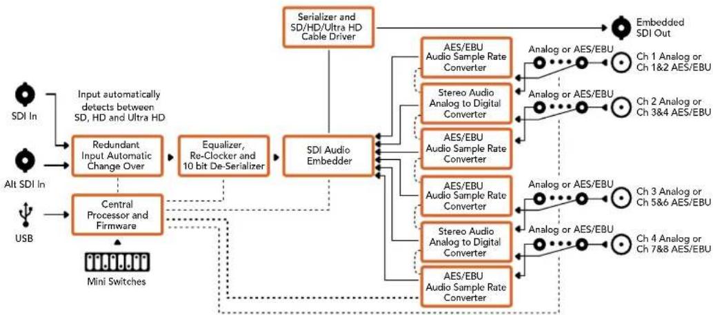
Mini Converter Optical Fiber
Modenb Mini Converter Optical Fiber BbInonHaeT OndHOBpeMeHHoe npeoobpa3ObaHne SDI-cirhana B ontuueckn H o6paTHo. KOHeBep TApOMaTHueckn nepeKIOuayetc Mexy SD, HD n 3G-SDI, npn 3OM oha HapabEnHn ABJIOTc NOHOCbTo He3aBNCmbIM. 3TO no3BOJAE THaHTeNo bHyBeNHTb paccTcHnne nepdaun SDI-cirhana. TaK, npn paBoTe c SD-Bndeo OHO doCTHraet 45 KM, B TO BPemKaK npn IcnoB3OBAHN TpaDnOHHoro MeHOrO Ka6eJe He npebblaaet 92 M. CnHAn 3G-SDI moXHo nepedaBaTa Ha 25 km!
Pa3beMbl
1 OPTICAL OUT
Ontueckn BixoC pa3bemom LC nna noeknouehn oHOMoBOrKa6eJra.
2 OPTICAL IN
Ontueckn BXoC pa3bemom LC nnoKIOHcHNOHOHOBOI KOaBJI.
3 3G-SDI OUT
SDI-BbIXoD C BNC-pa3bEmOM DnI NOkIIOueHnI TpaIuioHnHO SDI-OBOpyDoBaHHa.
4 3G-SDIN
SDI-BXoC BNC-pa3bemOM nIpoKIOUeHn TpaINIOHNOrO SDI-OBOpyDoBaHnA,
5 POWER +12V
Bxod nHTaHn 12 B.
Cxema coeHHeH Mini Converter Optical Fiber
SFP Optical Fiber Transmitter and Receiver Module
Mini Converter Optical Fiber 4K
3Ta Moenb BInonHReT OOnOBpeMeHHoe npeoobpaoBaHne CnHaJa SD/HD nn Single Link 6G-SDI B ONTuueckn H B oBpaTHOM HanpaBHeHN. Mini Converter Optical Fiber 4K abTomatueckn nepeKnUoaeTcMexdy SD, HD n 3G-SDI, npn 3Toom oba HanpaBHeHnaPraJIOTc nonHoCtBu He3aBnCmblIM. 3TO No3BOJAE T3aHTeNbHO yBeINuHTb paCtOaHne nepeDaHn SDi-CnrHana. TaK, npn paBoTe c SD-BnDeo ONo DoCTnRaet 45 KM, B To BPemKaK npn NcNoB3oBaHnn TpaDnIOHOro MedHoro KaBEn He npeBbIaAET 92 M. CnHaJ 6G-SDI MoXHO nepeDaBaTb Ha 12 KM!
Pa3beMbl
1 NopT MINI-B USB
Cnyxnt dna 6OBHbEnn BCTpoEHHOro IOMMHN-KOHBeptepa.
2 OPTICAL OUT
OHTUeCKn BbIXoD pa3beMOM LC nIPOKIIoueHn ODHOMoBOrO Ka6eJIa.
3 OPTICAL IN
Ontnueckn BXoC pa3bemom LC nnoKlueyn OndHomOboRokabena.
4 SDI OUT
SDI-BbXoC BNC-pa3bEmOM IJRA NOKIOUeHnra TpaNIOHOHorO SDI-OBOpyDobAHnA.
5 SDIN
SDI-BXoC BNC-pa3bemOM nIPOKIIIOUeHn TpaINIOHOHoro SDI-OBOpyDoBaHnA.
6 POWER +12V
Bxod nntaHn 12 B.
Cxema coeHneH Mini Converter Optical Fiber 4K

SFP Optical Fiber Transmitter and Receiver Module
Mini Converter Optical Fiber 12G
3Ta moIeBbIIOJIHReT OJHOBpeMeHHoe npeo6pa3ObaHne SD- nII HD-cnHana (Bnnotb do 12G-SDI) B onTIueckn noTOK n o6paTHo.
CneuaNBHe rHe3do no3BOJnEYT yCTaHOBnTb ONTHueckn SFP-Moynb no cTaHapTy SMPTE c noepkkon 3G-,6G-1112G-SDI.
YCTPOIcTBo aBOMaTnueeCKn BbIbnpaet fOpMaT nOobpaKeHnHa BxOe NNCNOb3yET erO Ha BbIXOe. Ipeo6pa3OBAHnE B dByX HappaBneHnx BbINONHReTcA BTOHOHO.
3To no3Bolnet 3aHHTeIbHO yBEnuHtbpacctOAHnepepaSDi-cnHa. TaK, np pa6ote c SD-Bndeo OHO doCTnraet 45 KM, B TO BPemKa KpN uCNoJIb3OBAHN TpaINIOHHORo MeHOrO ka6eJHe npeBbIwaet 92 M.CurHan 12G-SDIMoxHO nepeDaBaTb Ha WeCTb KNIOMeTPOB.
Pa3beMBi
1 OPTICAL OUT
Otnuueckn BbIXoD pa3bEmOM LC nna noKnIOUeHn ODNHOBOrKa6eIa.
2 OPTICAL IN
Otnuueckn Bxod cpa3bemOM LC nnoKIOUeHNOHOMOBOrKa6eIa.
3 SDI OUT
SDI-BbIXoD C BNC-pa3beMOM nIe noKJIIOUeHnR SDI-06OpyIDOBAHnR.
4 SDIN
SDI-BXoD C BNC-pa3bemOM IINI IOKIIIOUeHnSDI-OBOpyOBAHn.
5 POWER +6 to 36V
Bxod nitaHn6-36 B.ДлпnpedynpeKdEHHcnyaHOrO OTKIOUeHnHa 3JIeKTPueckOM pa3beme yctpoiCTBa npedycmOTpeHO pe3b60Boe coeHNHeHne.
Cxema coeHneH Mini Converter Optical Fiber 12G
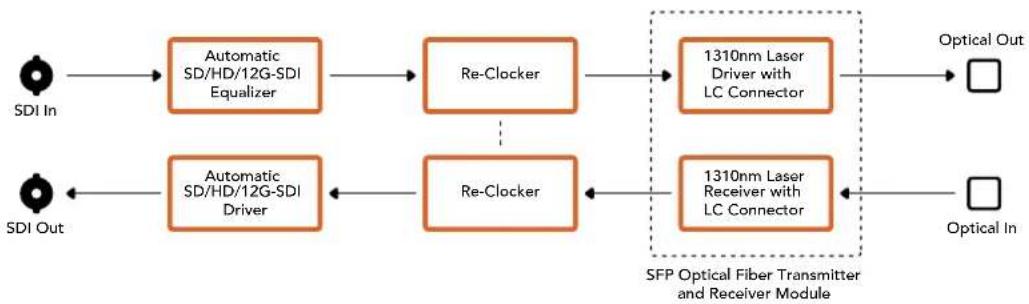
Mini Converter Quad SDI to HDMI 4K
Modenb Mini Converter Quad SDI to HDMI 4K no30B0n8et nepedaBt Ultra HD-Bndeo KaK odHo, DByx- nnnytebpexkahanbHbI SDI-cnHnHa nocneHne moenn HDMI-npoektopoB n TeNeBn3OpOB no OndHomy kabEnIO. Hxke nepeuNCHe bpyrue Bnbl cInHnOB, KOtpbE MoXHO BBODnTb Ha HDMI-nHTepfecc c nomoubTo 10rO KOHBepTepa.
SD-SDI
HD-SDI
Single Link 3G-SDI
- Single Link 6G-SDI
Dual Link HD-SDI
Dual Link 3G-SDI Ultra HD
- Quad Link HD-SDI Ultra HD
EcnK HDMI-BbXOy npKnIOueH HD-MoHTOp nN TeLEBn3Op, 6yET aTOMaTneCckn BblOnHeHa noHHkaoua KaHbepcna. Pnp paBoTe C cnHaIom Dual Link Heo6xOIMO nCNoJIb3OBaTB BXOdb1n2.
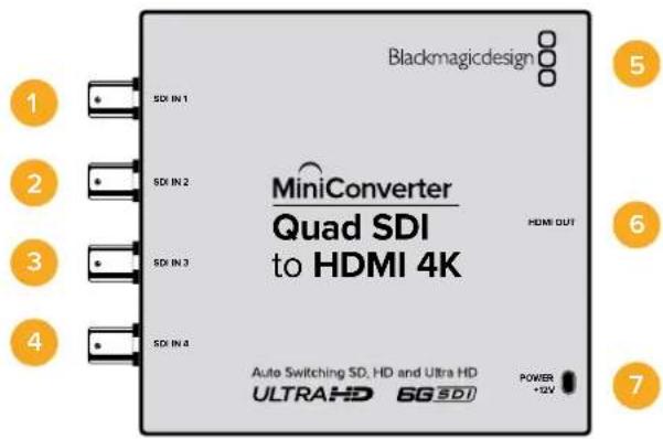
Pa3bembl
Hnke nepueuucneHb fopmatbI, noDpeKxBaembe Ha kaxdom SDI-Bxoide.
SDIn1
SD/HD-SDI
Single Link 3G-SDI
- Single Link 6G-SDI
Dual Link HD-SDI (kahan A)
Dual Link 3G-SDI Ultra HD (kaHAn A)
- Quad Link HD-SDI Ultra HD (kaHan A)
2 SDIn 2
Dual Link HD-SDI (kaHAN B)
Dual Link 3G-SDI Ultra HD (KaHAN B)
- Quad Link HD-SDI Ultra HD (KaHAN B)
3 SDIn 3
- Quad Link HD-SDI Ultra HD (kaHAN C)
4 SDIn 4
- Quad Link HD-SDI Ultra HD (kaHan D)
5 Nopr MINI-B USB
ObecneuBaet noKnHoueHnK Komblotepy c onepauonHOn ciTeMoM Mac OS X nn Windows dny paobTy cyTnHToB Blackmagic Converters Setup. TaKke cnYknt dnna 6bHOHeHH BCTpOeHHOro PO MmH-KOHBeptepa.
6 HDMI
HDMI-BbixoD TunaA.
7 POWER +12V
Bxod nHTaHn12B.
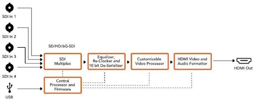
Cxema coeHHeH Mini Converter Quad SDI to HDMI 4K
Mini Converter SDI Distribution
MoEnb Mini Converter SDI Distribution no3BnReT oHOBpeMeHBOBOnTB SDi-CnHaHa BOCemb SDI-yctpoNCTB, B Tom uCnle deKn, BnDeocTeHb N Mkiuepbl. KoHBeTpEo obeCneuBaet ABOMaTHueckoe nepeKluOeHne MeJx y SD-SDI, HD-SDI n 3G-SDI, BInONHpaHpeHepauio CnHaHa H BOCBMn BixOax c noDnepkKo ASI, dononHntelhbx daHHbx IN BCTpoeHHoro 3Byka.
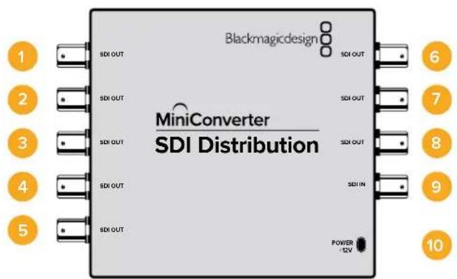
Pa3beMbl
1-8 SDI OUT
SDI-BbIXOaBc BNC-pa3beMaMm.
9SDIIN
SDI-BXoD.
10 POWER+12V
Bxod nuaHn 12 B.
Cxema coeHneH Mini Converter SDI Distribution
Mini Converter SDI Distribution 4K
MoIb Mini Converter SDI Distribution 4K no3B0n8eT oHOBpeMeHNO BvBODHTb SDI-cnrHa Ha BOCEMb SDI-yCTpoiCTB, B TOM uNcIe Iekn, BnuDeocTeHb I MNUkWepebl. KOhBeptep obecneuBaet abTomatueckoe nepeKluoyehne MeJy SD-SDI, HD-SDI, 3G-SDI n 6G-SDI, BvInonHra perHepaunio CnHana Ha BOCBM NByxOax c NoDaeppKoAI ASI, DOnONHITeNbHbIX daHHbIX n BCTPOeHHoro 3Byka.
Pa3beMbl
1-8 SDI OUT
SDI-BbIXOdb C BNC-paBemamn.
9SDIIN
SDI-BXoD.
10 POWER+12V
Bxod nntaHn12B.
Cxema coeHneH Mini Converter SDI Distribution 4K
Mini Converter SDI Multiplex 4K
Hnke nepuecnleBbDbl npoeobazohna, KOtOpbIe no3BOnraT bInoNHTb Moelb Mini Converter SDI Multiplex 4K.
PacnpedeeneHne cunHanOB SD/HD n 6G-SDI ha Bce yeTbpe bixoja.
Pacnpedenee CnHana Dual Link HD-SDI Ha Bce Yetbipe BbIXoJa 3G-SDI.
- Pteo6pa3oBaHne Single Link 3G-SDI B Dual Link HD-SDI.ДыхkaHaJIbHbI cHnBbBOIOITc Ha Oe napbl BbIXOOB.
- Пгобразовные Single Link 6G-SDI в Dual Link 3G-SDI wуn Quad Link 1.5G-SDI.
-П_REобразоване Quad Link HD-SDI Ultra HD B Single Link 6G-SDI nIu Dual Link 3G-SDI Ultra HD.Оьсесчьаet noклоченe Ultra HD-nCTochNKOB K Ultra HD-dnCJIpeM C DByXKaHbHoi nepedaue cnHana.ДБухKaHbHbI cnHan BBIOBNTcHa Obe napbl BbIXOOB.
- Ppeo6pa3oBaHne Dual Link 3G-SDI B Single Link 6G-SDI.
-Плесобразоване Dual Link 3G-SDI Ultra HD B Quad Link HD-SDI Ultra HD.Овесneyиьет покючени剥 Ultra HD-Источников Ha ochobe Dual LinkK Ultra HD-Dисплелм сутырекханальнои петдаун сигнана.
Pa3beMbl
1 POWER +12V
Bxod nHTaHn 12 B.
Hnke nepeuNCHehfoPMaTbnoepKnaembe Ha KaXdoM SDI-BxoJe.
2 SDIn1
SD/HD-SDI
Single Link 3G-SDI
Single Link 6G-SDI
Dual Link HD-SDI (kaHAn A)
Dual Link 3G-SDI Ultra HD (KaHAn A)
- Quad Link HD-SDI Ultra HD (kaHAn A)
3 SDIn 2
Dual Link HD-SDI (KaHAn B)
Dual Link 3G-SDI Ultra HD (KaHAN B)
- Quad Link HD-SDI Ultra HD (KaHAN B)
4 SDIn 3
- Quad Link HD-SDI Ultra HD (kaHAN C)
5 SDIn 4
Quad Link HD-SDI Ultra HD (kahan D)
6 NopT MINI-B USB
ObecneuBaet noKnHoueHnK KomNbIepey c onepauonHOnc nCTemOa Mac OS X nn Windows dny paobToC cyTnHToB Blackmagic Converters Setup. TaKke cnKynt dnna 6OBHeHHB CTePOeHHOro PO MmHi-KOHBeptepa.
Hnke nepeuucneHbI cOpMaTbI, noDpeKINBaembIe Ha KaJxOM SDI-BbxOJe.
7 SDI OUT1
SD/HD-SDI
- Single Link 3G-SDI
- Single Link 6G-SDI
Dual Link HD-SDI (kahan A)
Dual Link 3G-SDI Ultra HD (kahan A)
- Quad Link HD-SDI Ultra HD (kaHAn A)
8 SDI OUT 2
SD/HD-SDI
Single Link 3G-SDI
Single Link 6G-SDI
Dual Link HD-SDI (kaHan B)
Dual Link 3G-SDI Ultra HD (Kahan B)
- Quad Link HD-SDI Ultra HD (kaHan B)
SDI OUT 3
SD/HD-SDI
- Single Link 3G-SDI
- Single Link 6G-SDI
Dual Link HD-SDI (kaHAn A)
Dual Link 3G-SDI Ultra HD (kaHan A)
- Quad Link HD-SDI Ultra HD (kaHan C)
10 SDI OUT 4
SD/HD-SDI
Single Link 3G-SDI
Single Link 6G-SDI
Dual Link HD-SDI (kaHAN B)
Dual Link 3G-SDI Ultra HD (KaHAN B)
- Quad Link HD-SDI Ultra HD (kaHan D)
IpeeknloaTeJI
Mini Converter SDI Multiplex 4K imeeT nepekIOuATEEN, c nOMOU KOtOpbIX MOXHO BIBpaTb pa3nHHe HactpOnKn peo6pa3OBaHna.
Ipeeknouatei8,7u6-Format Conversion
KombuHaiaHn Hactpoek dnnpekeKluoatee 8,7 n6 no3BolarebblbpaTb HyKnBn BapnaHT npoeobaoBaHn, Hanpimep Dual Link HD-SDI B Single Link HD-SDI nnq Quad Link Ultra HD B Single Link Ultra HD.
Ipeeknouate1-Processing ON/OFF
Korda nepekniouateIb 1 haxoDITcB noloxeHN OFF (bIKn.), Mini Converter SDI Multiplex 4K BblonHre pOJIy cunntela CIRHana SD/HD/6G-SDI cero pacnpedeJeHem Ha etbpe BixOJa.
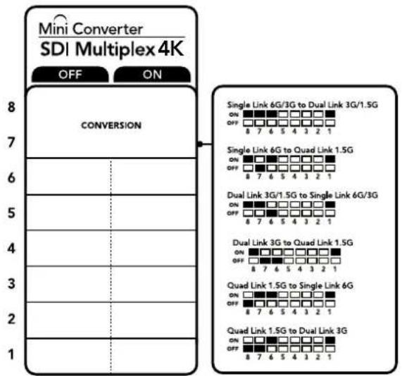
CxemaHa HnKHeH NOBepxHOCT KOpnyca CoepkHT OINCAHHe HAcTpoE, COOTBeCTByOuX pa3HBIM NIOJOKeHm NpeekUoateNei
Ppimep HactpoeK nepeeknouatele
Ecn Heo6xOIMO BbIOnHnB npeo6pa3OBaHne Quad Link Ultra HD B Dual Link Ultra HD, yctanobte nepeknoateB 8 B noLoXeHne ON (Bkn.), nepeKIOuATEB 7 - B noLoXeHne OFF (BbIK).
HactpoKn dIy npoe6pa3OBaHna SDI-cnHaHa
| Преобразовaines | Прееклоча给宝宝 8 | Прееклоча给宝宝 7 | Прееклоча给宝宝 6 | Прееклоча给宝宝 1 | Положения прееклоча给宝宝 |
| Преobразовaines Single Link 6G/3G- SDI в Dual Link 3G/1.5G-SDI | ON ON ON | ON | ON OFF 8 7 6 5 4 3 2 1 | ||
| Преobразовaines Single Link 6G-SDI В Quad Link 1.5G-SDI | ON OFF ON | ON | ON OFF 8 7 6 5 4 3 2 1 | ||
| Преobразовaines Dual Link 3G/1.5G- SDI в Single Link 6G/3G-SDI | ON ON OFF | ON | ON OFF 8 7 6 5 4 3 2 1 | ||
| Преobразовaines Dual Link 3G-SDI В Quad Link 1.5G-SDI | ON OFF OFF | ON | ON OFF 8 7 6 5 4 3 2 1 | ||
| Преobразовaines Quad Link 1.5G-SDI В Single Link 6G-SDI | OFF ON ON | ON | ON OFF 8 7 6 5 4 3 2 1 | ||
| Преobразовaines Quad Link 1.5G-SDI В Dual Link 3G-SDI | OFF OFF ON | ON | ON OFF 8 7 6 5 4 3 2 1 |
Cxema coeHneH Mini Converter SDI Multiplex 4K
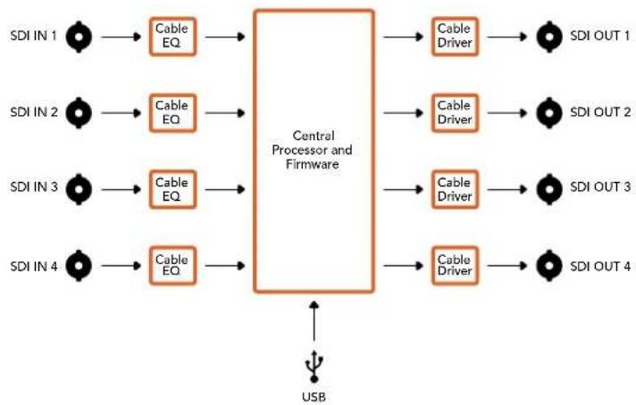
Mini Converter Sync Generator
Modenb Mini Converter Sync Generator Imeet Wectb Bixoob c KbaepoeBOn ctabnnaeue Hactotbl Ia CnHxpoHn3aunn OobpyObaHn c nmoouc nHana tri-sync (HD) nn blackburst (HD) B HeboIbwoI CTdynn nn Ha OTKpbIbX pnoaKaX.
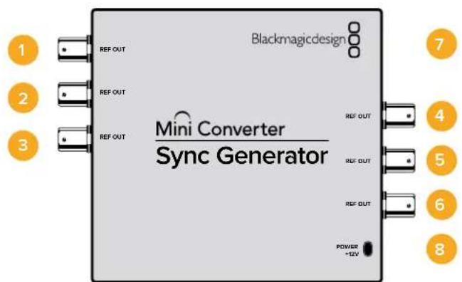
Pa3beMbl
1-6 REF OUT
CnHxpobbixoDbc BNC-pa3bemamn.
7 Nopt MINI-B USB
ObecneuBaet noKkUeHne K Komblotepy c onepaunHOHc nCTemO Mac OS X nn Windows dna paobt cyTnHToB Blackmagic Converters Setup. TaKxe cnJxnt dn oboHbIeHn BCTpoEHnO rIO MmH-KOBpeTepa.
8 POWER+12V
BxOД nITaHnI 12 B.
Pepeknloatei
Mini Converter Sync Generator Imeet nepeknoateen, c nmooskoKOTopbIX MOXHO BbipapTa pa3nHbHe HactpoKn pneo6pa3OBAHna.
IpekeKIOUaTeEN 4,3,2n1-SYNC REF FORMAT BIT 3,2,1n0
IpeekuoyateN4,3,2n1no3BOJnOHTBb6upatbΦopMaT,ncNoJIb3yEmbI dIaUN
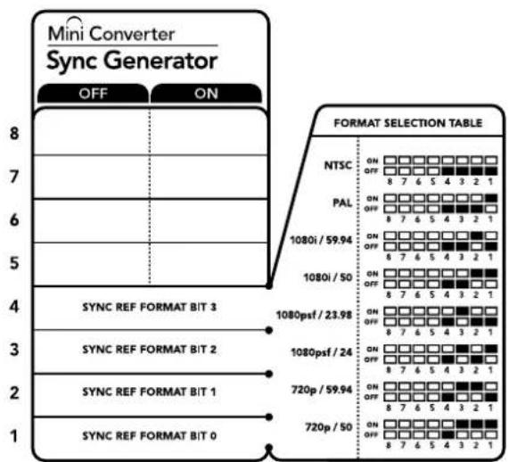
CxemaHaHnKHeiNoBepxHocTH Kopnyca CoepkHT OnnCaHne Hactpoek, COOTBETCTByOuXnx paaHbIM NoIOKeHNsM IpeKIIouateIeN
Ta6nua noDepknaBaembix φopMaTOB
| Формат Виdeo | Переклочател 4 | Переклочател 3 | Переклочател 2 | Переклочател 1 | Положения переклочател |
| NTSC OFF OFF OFF | ON OFF 8 7 6 5 4 3 2 1 | ||||
| PAL OFF OFF ON | ON OFF 8 7 6 5 4 3 2 1 | ||||
| 720p/50 OFF ON ON | ON OFF 8 7 6 5 4 3 2 1 | ||||
| 720p/59,94 OFF ON ON OFF | ON OFF 8 7 6 5 4 3 2 1 | ||||
| 720p/60 ON ON ON OFF | ON OFF 8 7 6 5 4 3 2 1 | ||||
| 1080i/50 OFF ON ON | ON OFF 8 7 6 5 4 3 2 1 | ||||
| 1080i/59,94 OFF ON OFF | ON OFF 8 7 6 5 4 3 2 1 | ||||
| 1080i/60 ON OFF OFF | ON OFF 8 7 6 5 4 3 2 1 | ||||
| Формат виdeo | Переклоча Temple 4 | Переклоча Temple 3 | Переклоча Temple 2 | Переклоча Temple 1 | Положенияпереклоча Temple |
| 1080PsF/23,98 OFF ON OFF OFF | ONOFF8 7 6 5 4 3 2 1 | ||||
| 1080PsF/24 OFF ON OFF ON | ONOFF8 7 6 5 4 3 2 1 | ||||
| 1080p/23,98 ON ON OFF ON | ONOFF8 7 6 5 4 3 2 1 | ||||
| 1080p/24 ON ON OFF | ONOFF8 7 6 5 4 3 2 1 | ||||
| 1080p/25 ON OFF ON ON | ONOFF8 7 6 5 4 3 2 1 | ||||
| 1080p/29,97 ON OFF ON OFF | ONOFF8 7 6 5 4 3 2 1 | ||||
| 1080p/30 ON OFF ON | ONOFF8 7 6 5 4 3 2 1 |
Cxema coeHneH Mini Converter Sync Generator
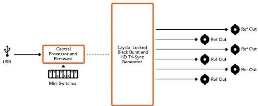
Mini ConverterUpDownCross
Modelb Mini Converter UpDownCross BbInonHaeT noBbIaOuSyo, noHnKaoUyio, nepeKpctHyu npOpMaTHyIO KOHBPcNIO. 3OT KOHBPTEp TAKKe oEocneuBaET npeo6pa3OBAHne MeJxNy NTSC n PAL, 720p n 1080i. Kpome toro, moXHO MeHrTB npOnopun KaJa: BO Bpemra NobIaOuSei KOHBPcNIO DOCTynHbI onu 4:3 Pillarbox n 16:9 Zoom, npn noHnKaUoSei KOHBPcNl - Letterbox 4:3 n Anamorphic 16:9.
Kornda nepeeknouateIb KOHbpcn yctaHOBHe B noIOxKeHne OFF (BbIKI). KOHbpTeP BbINOHreT poIy cunntela-pacnpedeJInte SDI-cirhana.
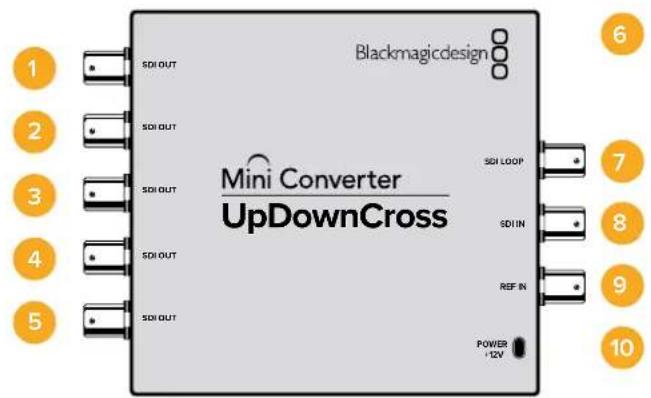
Pa3beMbl
1-5 SDI OUT
SDI-BbixOdbicBNC-pa3beMaMn.
6 Nopt MINI-B USB
ObecneuBaet noKnouHne K KombTopey c onepaOnHHoC nCTeMoN Mac OS Xnnn Windows na pabotc ytnntoB Blackmagic Converters Setup. TaKke cnjxnt dnoobHHeHn BCTpoEHHO rO MmHn-KOHBeptepa.
7 SDI LOOP
CKBO3HOB BbIXOd nIy BbIBOda BXoJrEro CnHa.
8 SDIN
SDI-BXoJ.
9 REF IN
CnHxpoBxoJ.
10 POWER +12V
Bxod nntan12B.
Ipeeknloatei
Mini Converter UpDownCross Imeet nepeKIOUaTeI, c NOMOUIKO TOpIX MOXHO BbIpaTb pa3HHe HAcToPkn Ppeo6pa3OBaHn.
IpeeklouateIb 8 - Ipeo6pa3oBaHne nponopun kaPra
Kombuhaunnepeknquateen8n7no3b0laotBb6paTbponopunKaopa npn BblnoHeHH noBbIaoue n noHxkaiooey KOHbepcn. Hanpimep, ecn npn noHxkaiooey KOHbepcm nepeknquateen8n7yctahOBnBeBnB noOxoehne OFF (BbIKn), 6ydtncnolb3oBaTbcra pekm Letterbox.
Ipeo6pa3oBaHne nponopcui KaPa
CkBo3HOB BbIXoIyBbBOda noCTyaIooJero SDI-n3O6paKeHHa.
3 HDMI IN
HDMI-BXOD TnA A. Ppi OOBAPyKeHN BXOJUeero HDMI-CnHana HaHHaET MmTaTb HeoBbWOn CBToNDnHbN INHnKaTOp, KOtOpbH AxOHTcPraOM C pa3beomHDMIN.
4 REF IN
CnHxpoBxoJ. Ha coctoHne CnHxpoBxoJa yka3bIbaeT He6oJIbIoN CBTeOIOHOHbI INHdkatop paoom CpazbemOM REF IN. BeIoro UCBeta, rOpIT NOCTOARHO -ΦOpMaTbIOCTyauoero CnHxpocnHaHa n 306paXeHna Ha BbIXOe COBnadaIoT. BeIoro UCBeta, MIRaet - NoCTynaoos CnHxpocnHaHa He COBnadaet noΦOpMaTy c N3O6paXeHem Ha BbIXOe.
5 NopT USB-C
Cnyknt nnoKIOUeHn K KombIOTepy c onepauHOHcNCTemOu Mac OS Xnn Windows n ynpaBHeHn c nmoCbIO yTNIITb Blackmagic Converters Setup. TaXke no3BOJAreT BbINOHNrTb OHOBHeHne BCTpoEHORo MmHn-KOHBePtepa.
6-7 SDI OUT
SDI-BbIXOdb C BNC-paBemamM
8 HDMI OUT
HDMI-BbixoTnA.
9 POWER +6 to 36V
Bxod nntahn 6-36 B.ДлпnpedynpeckdneHn cnyaHoro OTKNIOUeHn Ha 3IeKTPueckOM pa3beme yctpoiCTBa npedycmOTpeHO pe3b6OBoE coeHNHeHne.Пр nOdaue 3HeprHu NaHnaet Mrratb HaxoJusncra pAOM He60JIbwo CBTeODNoDHy INHdkaTOp.
Pepeknloatei
Mini Converter UpDownCross HD Imeet nepekniouatei, c nmoocbo KOTopbix MOKHO Bbipap Ta pa3nuehhe hactpoikn ppeo6pa3oBaHn.
Ipeeklouate1- Processing Off/Processing On
Korda nepeeknoateB 1yctaHOBnE H noLoXeHne OFF (bblkI), npeoobpazObaHne He BblonHaeTcB 3tOM clyuae KOHBeptep MoxHO nCnonb3ObaTb dRn BbIBDa CnHana Ha SDI-nnn HDMI-nHTepfec.
EcnnepeknioateIb 1 HaxoIITcB noLoKeHHN OFF (BbIKn.), SDI- nHDMI-cnHaJIb Ha BbXOe COBnaIaOT C COOTBeCTByIOUIMM NOtOKAMn HA BXOe.
Korda nepekliouateIb 1yctaHOBneH B noLoXeHne ON (BKn.), BblnoHHeTc npeo6pa3ObaHne, a nepekliouateIe c 4 no 8 nCnONb3yOTc dIra HAcTPOuN BbIXoHOro CnHaJa KOHBepTepa.
Ppeeknouateb 2 - Level A n Level B nn 3G-SDI
Korda nepekniouateB 2 yctahobnEN B noJoxeHne OFF (bblKn), dna cnHana 3G-SDI nCnoB3yETcR Level B. Korda nepekniouateB 2 haxoNTcR B noJoxeHn ON (Bkn), dna cnHana 3G-SDI nCnoB3yETcR Level A. 3To no3BOJAE T aadTb cnooc nepeDaun 3G-SDI B COOTBeCTBn C xapakTepcntkamn npyroro SDI-obopydoBaHn.
COBET. Ecn nocne nooknuehenna nctouhka 3G-SDI k ahanorunhyomy obopyoBaHIO cnHn He o6hApUkeH, n3MeHnte noLoXeHne nepeKIOuHaTeTn2, notomy yTO yCTpoiCTBa mOryt nCnOJIb3OBAt b pa3HbIe cnOCobI nepeaun taKOro CnHana.
Ipeeknouateenn 4-8
C NOMOIOInepeKIOUaTeNei C 4 NO 8 MoXHO 3aIaNb FOpmM N CTaHApT CuHaHa Ha BbIXOe KOHBePepa. IyDObCTBa paobToB c HmN Ha HxHHe CTopoHE KOpNyca ectb HaHJIAHAR CXema.
Pnmeh Hactpoek nepeKIOuateJe
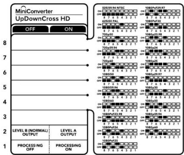
Ta6nua noDepknaBaembix fOpMaTOB
| Формат Виdeo | Переклочател 8 | Переклочател 7 | Переклочател 6 | Переклочател 5 | Переклочател 4 | Положения пегеклочател |
| 525i/59,94 NTSC | OFF OFF OFF | OFF OFF OFF | ON OFF 8 7 6 5 4 3 2 1 | |||
| 625i/50 PAL OFF | OFF OFF OFF ON | ON OFF 8 7 6 5 4 3 2 1 | ||||
| 720p/50 OFF OFF ON OFF | ON OFF 8 7 6 5 4 3 2 1 | |||||
| 720p/59,94 OFF OFF ON ON | ON OFF 8 7 6 5 4 3 2 1 | |||||
| 720p/60 OFF ON OFF ON | ON OFF 8 7 6 5 4 3 2 1 | |||||
| 1080i/50 OFF ON OFF ON | ON OFF 8 7 6 5 4 3 2 1 | |||||
| 1080i/59,94 OFF ON ON OFF | ON OFF 8 7 6 5 4 3 2 1 | |||||
| 1080i/60 OFF ON ON ON | ON OFF 8 7 6 5 4 3 2 1 | |||||
| 1080PsF/23,98 OFF ON OFF OFF | ON OFF 8 7 6 5 4 3 2 1 | |||||
| 1080PsF/24 OFF ON OFF ON | ON OFF 8 7 6 5 4 3 2 1 | |||||
| 1080PsF/25 OFF ON OFF ON | ON OFF 8 7 6 5 4 3 2 1 | |||||
| 1080PsF/29,97 | OFF | ON | OFF | ON | ON | ON OFF 8 7 6 5 4 3 2 1 |
| 1080PsF/30 OFF ON ON OFF | ON OFF 8 7 6 5 4 3 2 1 | |||||
| 1080p/23,98 | OFF | ON | ON | OFF | ON | ON OFF 8 7 6 5 4 3 2 1 |
| 1080p/24 OFF ON ON ON OFF | ON OFF 8 7 6 5 4 3 2 1 | |||||
| 1080p/25 OFF ON ON ON ON | ON OFF 8 7 6 5 4 3 2 1 | |||||
| 1080p/29,97 | OFF ON ON ON OFF | ON OFF 8 7 6 5 4 3 2 1 | ||||
| 1080p/30 | ON OFF ON OFF ON | ON OFF 8 7 6 5 4 3 2 1 | ||||
| 1080p/50 | ON | OFF | OFF | ON | OFF | ON OFF 8 7 6 5 4 3 2 1 |
| 1080p/59,94 ON OFF ON ON | ON OFF 8 7 6 5 4 3 2 1 | |||||
| 1080p/60 | ON | OFF | ON | OFF | OFF | ON OFF 8 7 6 5 4 3 2 1 |
Hacrtpoyn ytninbl Blackmagic Converters Setup
Ytuna Blackmagic Converters Setup no3B0JET MeHb TaKne HAcTpoKn MHN-KOBepTepa, KaK nponopuN kaPra, n o6HOBnIb ero nporpaMMHoe oecneueHne. 3aHaHHbe npaMeTpbl coxpaHIOrTa daxe noCne oTKJIoueHn yCTpoiCTBa. IJa DoCTyNa K Hm NcNoJIb3yOT BknaDkn Video, Audio n About.
Pa60a c Bknaiko About onncaHa B pa3dene «IImeHHe HactpoeK
BklaKa Video nIa Mini Converter UpDownCross HD daet BO3MOXHOCTb Bbipatb onncaHHbe HIXe onu.

Bkndka Video ytnnbl Blackmagic Converters Setup noBonaet yctahOBntb nponopun Kaepd nla SD-n3o6paeHna
PpOnpuKaIpaIaSD-n3o6paXeHnA
3Ta Hacptponka no3BOJnEe BbIbOaHtB n3o6paXeHne c nponopzmaM KApda 4:3 nn 16:9. Ecn Ha BXoNocTynaET SD-BnDeo C COOTHOWeHem CTOpOH 4:3 nn 16:9, To npu BbOpe COOTBeTCTByUoSe onuNN MoXHo CoXPaHNTb foPmT NoCTyNaIOUero CnHaHa.
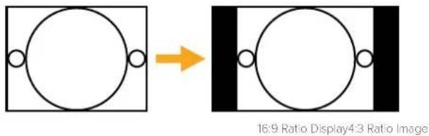
IymoJauHNO SD-BuJeO BbBOIDTC C npOpucnAMKaJa4:3,HoPiN Heo6XoIMOCtM MoxHO NcONb3OBaTcooTHoWeHne 16:9.HyXHyIO onuio BbBipaiOT HaBKnaKe Video.
Blackmagic Battery Converter
Battery Converter SDI to HDMI
Moelb Battery Converter SDI to HDMI no30bnert Bbboinb n3o6paekhe c SDI-obopyoaba Hn dncnn en Bindeonpoektopc hSDMI-nHTepceom. Nocne aBtOMaTneckoro Bb6opa SD, HD n3G-SDI bInonHnreTc npoepa3oBaHnE CnHaCo BCtpaanBaHnEm 3Byka. KOHebpTe pMeet Kopnyc n3 abnaunOHHO aNkOMHHy, yToPnEHHbIe pa3bEmbl N BCTpoEHHyO 3apraKaemyO baTapeIO.
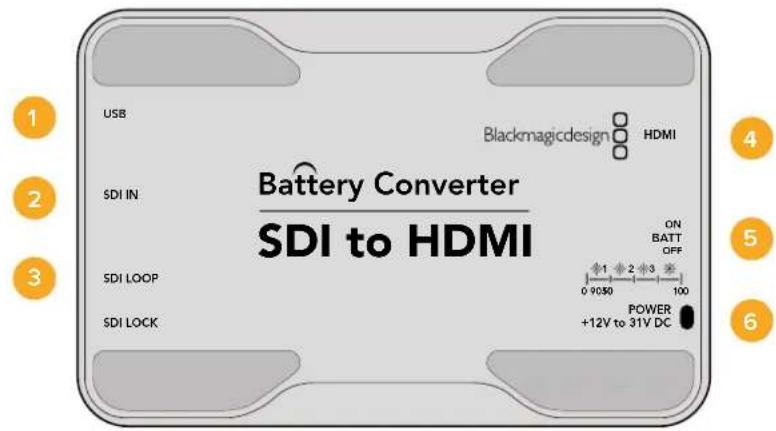
Pa3beMbi
1 NopT MINI-B USB
ObecneuBaet noKnHoueHn K Komblotepy c onepauonHOn ciTeMeo Mac OS X nn Windows dny paobToC cyTnHToB Blackmagic Converters Setup. TaKke cnxNt dn naOBHeHH BCTpoEHHO rO MmH-KOHBeptepa.
2 SDIN
OCHOBHoi SDI-BXoD C BNC-pa3bEmOM.
3 SDI LOOP
CKBO3HOI SDI-BbIXOc BNC-pa3beMOM.
4 HDMI
HDMI- BbIXoD Tnna A.
5 ON BATT OFF
IpeeknoyateB nHTAHN. KOrda OH yctaHOBHe B noLoXeHne On, KOHBepTep 6ydt npdoJnxb paOtaB daJe np otKIOUeHN BHeuHero nCTouHnka.Ecnn IpeeknoyateB haxoDITcB nNoXeHm Off, nCnoJIb3ayETc TOnbKO BHeuHHe nTahHe. CBeToNDHb INDnKaTOp pAOM c nepeKIOUaTeMe rOpNT HepepeBnHO, KOrda 6atapera 3apJxHa Ha 100%, mraet trp i dBa pa3a npz 3apJe 50-90% n 10-50% COOTBETCBEHNO, a npn ypOBHe Mehee 10% 3aropaetc n rachet.
6 POWER +12V
Bxod nitaHn 12 B.
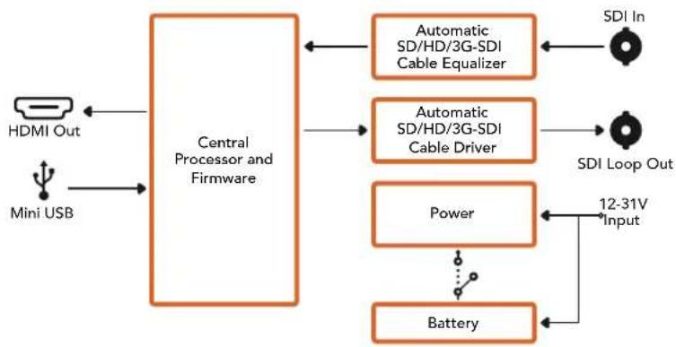
Cxema coeHneHn Battery Converter SDI to HDMI
Battery Converter HDMI to SDI
Moelen Battery Converter HDMI to SDI no3B0n8et BbBODntcHnHDMI-yctpoiCTB (taknx kak HDV-kamepbu nrgpOBe KOHCOH) Ha texhny c SDI-nHTepfcom. Bnaorapr 3omy moKHO nepeDabatnbno6paXeHne n3 HDM-ntOchUHKa no SDI-Ka6eIO HA 6oNbUoe pacCTOHHne, a TAKKe npoknouTb KOMbIoTeP K SDI-o6OpdyOBaHNIO. KOHeptep IMeET Kopnyc n3 abuaunOHoro aniomHHy, yToJIeHHBe pa3bEmu BCTpoEHHy 3apJxMaMyo 6aTaapeIO.
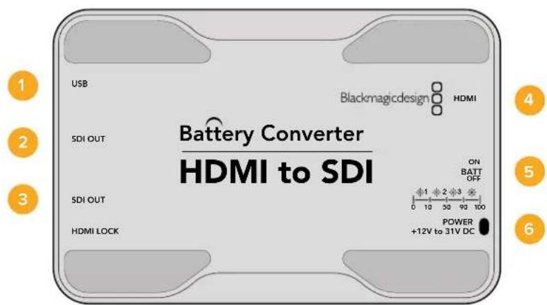
Pa3beMbl
1 NopT MINI-B USB
ObecneuBaet noKnHoueHnK KomNbIopepy c onepaunHOHc nCtEmoM Mac OS X nn Windows dna paobTu cyTnHToB Blackmagic Converters Setup. TaKke cnYxnt dn naOBHeHn BCTpoEHnro IIO MNH-KOHBeptepa.
2 SDI OUT
SDI-BbIXOc BNC-pa3beMOM
3 SDI OUT
Btopoi SDI-BbIXoD
4HDMI
HDMI-BXoD TnA A.
5 ON BATT OFF
IpeeknIOuateIb nHTAHN. Korda OH yctahOBHeB NOIOKeHne OOn, KOHBepTeP 6yET npOdoJIkATb paOToTb daxe npn OTKIOUeHm BHEHrero nCTOHyHKa. EcnI nepeKIOUcATEIb HaxoITCB NIOJOKeHm Off, IcNoIb3yETc TOLbKO BHEHHe nITAHHe. CBeTOIDnHb INHdkatop pIOM C nepeKIOUaTeHem rOpNT HeHpepbIBHO, KOrda 6batape 3apJxHa Ha 100%, mraet trp n IBa pa3a npn 3apJe 50-90% n 10-50% COOTBETCTBENHO, a npn ypOBHe MeHHe 10% zaropaetc n rachet.
6 POWER +12V
Bxod nHTaHn 12 B.
Cxema coeHneHn Battery Converter HDMI to SDI
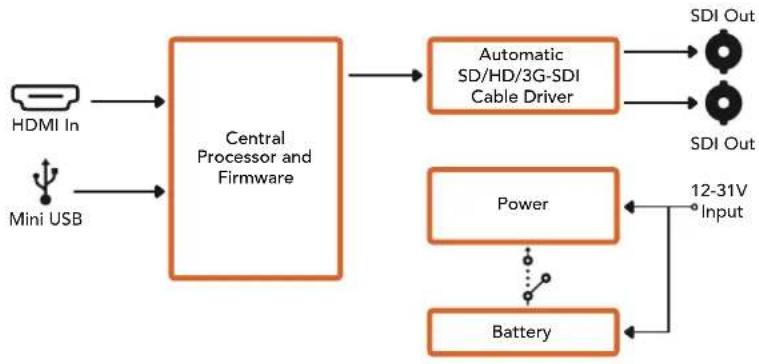
POMOUsb
Kak nojuyntb nomoucb
Cambibbicpbn cnooc noyntb nmoosb - o6paNTbcra K ctpanuam npndepkna Hcaine Blackmagic Design n npobepntb hannue noceednx cnpabouhbx MaTePnaNoB no Blackmagic Converter.
CtpaHua noDpeKKn Ha caIte Blackmagic Design
IocneHnE BepnnpykoBODCTBa no 3Kcnnyatau, nporpaMMHO o6ecneHn IdoonHntelbHyIO uHFPoMaUIO moKHO hainB pa3dene nOeepKKn Blackmagic Design Ha cTpaHnce www.blackmagicdesign.com/ru/support.
Φopym coo6eCTBa Blackmagic Design
NoIe3HbIM NCTOCHIKOM INHΦopMaUN RAIBaTeC ΦOpym COo6UeCTBa Ha Be6-caTBe Blackmagic Design. Ha HEM MOxHO NODeJIITbcra CBOUMN UeERMn, a TaKKe NOLyUHTb NOMOuB OT nepcoHaHa noIDepkKn I dpynx NoIb3OBAteNei. AApec fOpym http://forum.blackmagicdesign.com.
06paueHnE B Cnyx6y nopepkk Blackmagic Design
Ecni c nOmoIbKO DoCTynbIX CnpaBOUYbIX MaTePnAIOB N φOpyma peuHt b npObnemy He ydAnocB, BOCNoJIb3yIteCb fOpMOI OITnpaBVt HAM COo6UeHne> Ha cTpaHnCe IOnDEpKKn. MoKHO TaKKe NO3BOHHTB B 6nHexaJWe npedctabUTenbCTBO Blackmagic Design, TenefoH KOtOPoro Bbl HaJdeTe HA Hauem Be6-caite.
PpOBepKa IcNoIb3yEmoB BercnI pporpaMMHoro o6ecneueHna
YTo6bI yHaTb BepcHIO Blackmagic Converters Setup, yTaHOBHeHHyIO Ha BaUeM KOMNbTepe, oTKpOte OKHo About Blackmagic Converters Setup.
- Pn pa6ote B onepaunHnoHc nCteMe Mac OS X oKpOte Blackmagic Converters Setup B nankke «PnpioKeHHB. MeHIO BbIepeTe About Blackmagic Converters Setup, y3HaTb HOpE BepCn.
- Пи работе В onepaционн сстeme Windows 7 окposу Te MeHIO «Пуск» N bblepeite Blackmagic Converters Setup.В мeHIO «Помошь» bblepeite About Blackmagic Converters Setup,чroбы узath Homep BCPSN.
- Пи павоте в onepaunnoHOn cinTeMe Windows 8 Ha ekpahe «Пуск» Вьберпte Blackmagic Converters Setup.В мeню«Помошь» Вьберпte About Blackmagic Converters Setup,чтобу уз hav Homep Верси.
3arpy3ka nocleDnHex Bepcn nporpamMHO o6ecneueHna
Y3nab yctahOBHeHny Bepcno ytnntb BlaKmagic Converters Setup, npeynte B ceHTp noDnepxKn Blackmagic Ha ctpaHnce www.blackmagicdesign.com/ru/support, TObbl npoBepntb HauNue o6HOBJIeHni.
PekomeHdyetcBcerdaNCnolb3OBaTbNocneHIOBepCNO nporpaMMHOO oBeceHn,ODhako 0bHOJIeHnJeUHe Bcero BblONHrTb Nocle 3aBepSeHnTeKyIeTo pOeKaTa.
Гаранту
OrpaHnueHHa rapaHTncaPOKom 12 mecayeB
Komnannia Blackmagic Design rapaHTnpyET oCytCTBne B npOdykTax Mini Converter n Mini Converter Heavy Duty depeKTOB mATEPnana n npOn3BODCTBEHHORo 6paka B TeueHne 36 MeaCEB c DaTb npodaxn. Dnpa paBemOB, KaBene, onTnecknx MOnyene, npdoxpanTeeN n AKKymIaTOPbix batape TakaR rapaHTNcoCTabnre12 MeaCeB C daTb npodaxn. Dn moNeB Battery Converter rapaHTN OTCyTCTBn DEpeKTOB mATEPnana n npOn3BODCTBEHHORo 6paka DeiCTByet B TeueHne 12 MeaCeB C daTb npodaxn. EcnBo BPemra rapaHTnHOrO cPoka BydYt BBInBeHbIepeKtB, Blackmagic Design no Cboemy ycmTopeHHIO BblONHIT pEmOH THeNCnPABHORO I3DeJIa N3DeJIa N3OnAaTb CTOnMOCTI 3anactei n TpyDo3aPat ININ 3ameHNT TaKoe IN3DeJIe HOBbIM.
YtobbocnojBzOBaTcHactoJepaHTne,notpebntb oBa3aH yBeOMITb KOMnHIO Blackmagic Design o defekeTo do OKOHuaHra paHTnHorO cpoKa n oecneuHt b ycNOBn dI npedocTabHeHn Heo6xOdBix ycny. Notpebntb Hecet OTBETCTBEHHOCt b 3a yNaKOBky N DOCTABKy HeNCpabHoro n3dEINB B COOTBETCTByUOni cepBnCHbI CEHTP Blackmagic Design c onlatoN noTOBbIX pacXoDB. Notpebntb oBa3aH ONlAInTB BCE paxOdbI NO DOCTABKe I CTpaxOBaHIO, NoJINHbI, HALrN INHbI cbOpbI B CBA3N C BO3BpaOM n3dEINB Bhe 3aBnCmOCTN O T pNCHb BO3BpTa.
Hactoia rapaHTna He pacnpocpTaHareTc H daepeKbI, OTKa3bI NOBpeXdeHnB, Bo3HKwne n3-3a Headexaero nCnoBzOBAHn, HenpaBnBHO yXOda nn o6CnyxuBaHn. KomnaHn Blackmagic Design He o8raHa npedocTaby cLytn no Hactoae rapaHTn: a) dln yCTpaHene HOBpeXdeHn, BO3HKwix B peyIbtaTe deCTbn no yctahOBke, pemOnTy nn o6CnyxuBaHnIO n3dEInra Iuaam, KOTopbIe He ABJOTc nepcoHaiom Blackmagic Design; 6) dln yCTpaHene HOBpeXdeHn, BO3HKwix B pezyIbtaTe Headexaero nCnoBzOBAHn nn nockluoyehn K HecOBmecTMOMy o6OpDobAHIO; B) dln yCTpaHene HOBpeXdeHn nn deFeKToB, Bbl3BaHHbx INCNoB3OBaHnEM 3aIacTei nn MATEpnaIOB dpyrnx npOn3BOAnTei; r) ecIn n3dEInne bblNO moNphiuropoAoHnn INTEprnpoBaHO CDPyIM o6OpDobAHnEM, KOJa TaKaMoiNfkaunn nn INTERpaunr yBeJIuYBaET BPEMa nn NOBbIaet cNoXHOCTb o6CnyxuBaHn nn dEInna. HACTOIA RAPAHTN R PDEOCTABJARETCOMPAHNE BLACKMAGIC DESIGN BMECTO LIOBX DpyTN PPRAMO BIPAXEHbIX NN IOPA3UMEBAEMbIX TAPAHNT. KOMPAHNA BLACMKAGCDESIGN NEE DNIEPbI OTKA3bIBAOCTCR OT LIOBX NDOPA3UMEBAEMbIX TAPAHNT KOMMEPUECKO UEHHOCTN NIN INPNFOIDHOCTN DIA KAKOI-JINBO ONPEDELEHHOUIELNI. OTBETCTBEHHOCTb BLACMKAGCDESIGN IOPEMOHTU NIN 3AMEHE HENCPABHBIX N3DEINN JABJETCR NOINbIM INCKLIQUHTeNBHM CPEICTBOM BO3MEUHEN, PEPDOCTABLREMBI NOTPEBNTELIO B CBJ3N C KOCBEHHBM, AOKTIUECKIM, CONYTCTBYIOUIMN INOCLEUYIOUIMN YbITKAMN, BHE 3ABNCMOCTN OT TOGO, BILNA INI Het KOMPAHNA BLACMKAGCDESIGN (INI50 EE INIEP) PEPDBAPITEHO N3BEUEHA O BO3MOXHOCTN TAKNX YbBITKOB. BLACKMAGIC DESIGN HE HECET OTBETCTBEHHOCTN 3A IPOTNBOIPABHOE INCNoB3OBAHNE O6OPUJOBOAHN CO CTOPOHBI NOTPEBNTEL. BLACKMAGIC DESIGN HE HECET OTBETCTBEHHOCTN 3A IPOTNBOIPABHOE INCNoB3OBAHNE O6OPUJOBOAHN CO CTOPOHBI NCLEDCTBVE INCNOB3OBAHN 3TOGO IN3DEINN. PNCKN, CBJ3AHNbIE C EFO 3KCIIVYATALNEE, BO3JIAGAOTCn HA NOTPEBNTEL.
Copyright 2018 Blackmagic Design. Bce npaba 3auuueh. Blaekmigc Design, DeckLink, HDLink, Workgroup Vidcohub, Multibridge Pro, Multibridge Extreme, Intensity "Leading the creative video revolution" apernctpipobahk kak ToBapHbe 3nA IN ppynx cpaHax. HaaBHIN dpyNk KOMHIN HAHMeHOBAHIN IpOuyKTOB MOrT RnTbCn TOBAPHBMn 3HaKaAMN COOTBCTByIOx npabocnaadatcn.

Mini Converter Audio to SDI 779
Mini Converter Audio to SDI 4K 783
Mini Converter Optical Fiber 787
Mini Converter Optical Fiber 4K 788
Mini Converter Optical Fiber 12G 789
Mini Converter Quad SDI to HDMI 4K 790
Mini Converter SDI Distribution 791
Mini Converter SDI Distribution 4K 792
Mini Converter SDI Multiplex 4K 793
Mini Converter Sync Generator 796
Mini Converter UpDownCross 799
Mini Converter UpDownCross HD 803
Battery Converter HDMI to SDI 808
Asslstenza 810
Garanzia 811
2 L - ANALOG or AES/EBU
2 L-ANALOG or AES/EBU
- Clip video output to legal levels
2 L - ANALOG or AES/EBU
Interru tlore 7 - LUT Off, LUT On
Interruftore 5 - LUT On Loop Off, LUT On Loop On
| Canali audio | Interruttore 4 | Interruttore 3 | Interruttore 2 | Posizione |
| 1 and 2 OFF OFF OFF | ONOFF87654321 | |||
| 3 and 4 OFF ON | ONOFF87654321 | |||
| 5 and 6 OFF ON OFF | ONOFF87654321 | |||
| 7 and 8 OFF ON | ONOFF87654321 | |||
| 9 and 10 ON OFF | ONOFF87654321 | |||
| 11 and 12 ON OFF ON | ONOFF87654321 | |||
| 13 and 14 ON ON OFF | ONOFF87654321 | |||
| 15 and 16 ON ON | ONOFF87654321 |
- Clip video output to legal levels
2 L-ANALOG or AES/EBU
2 L - ANALOG or AES/EBU
Mini Converter SDI to Analog
4 L-ANALOG or AES/EBU
4 L-ANALOG or AES/EBU
Mini Converter Analog to SDI
4 L-ANALOG or AES/EBU
Mini Converter SDI to Audio
1 CH 1 ANALOG or CH 1 & 2 AES/EBU
1 CH 1 ANALOG or CH 1 & 2 AES/EBU
Mini Converter Audio to SDI
1 CH 1 ANALOG or CH 1 & 2 AES/EBU
4 CH 4 ANALOG or CH 7 & 8 AES/EBU
1 CH 1 ANALOG or CH 1 & 2 AES/EBU
4 CH 4 ANALOG or CH 7 & 8 AES/EBU