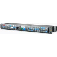
Teranex AV - Audio/video converter Blackmagic Design - Free user manual and instructions
Find the device manual for free Teranex AV Blackmagic Design in PDF.


| Product Type | Professional audio/video converter |
| Model | Teranex AV |
| Brand | Blackmagic Design |
| Dimensions | 190 x 120 x 45 mm (L x W x H) |
| Weight | 0.5 kg |
| Power Supply | 12V DC, 1.5 A (power adapter included) |
| Power Consumption | 18 W maximum |
| Video Inputs | 1 x SDI, 1 x HDMI |
| Video Outputs | 1 x SDI, 1 x HDMI |
| Supported Video Formats | SD, HD, 3G-SDI and HDMI up to 1080p60 |
| Audio Inputs | 1 x XLR stereo, 1 x RCA line input |
| Audio Outputs | 1 x XLR stereo, 3.5mm headphone output |
| Main Functions | SDI-HDMI conversion, audio embedding/de-embedding, genlock synchronization, audio re-sampling |
| Maintenance and Cleaning | Unplug the device before cleaning. Use a soft, dry cloth. Do not use solvents. |
| Safety | Use only the supplied adapter. Do not expose to moisture or extreme temperatures. |
| Spare Parts and Repairability | Contact Blackmagic Design support. No user-serviceable parts. |
| General Information | Operating temperature: 0°C to 40°C. Humidity: 0% to 90% non-condensing. |
Frequently Asked Questions - Teranex AV Blackmagic Design
User questions about Teranex AV Blackmagic Design
0 question about this device. Answer the ones you know or ask your own.
Ask a new question about this device
Download the instructions for your Audio/video converter in PDF format for free! Find your manual Teranex AV - Blackmagic Design and take your electronic device back in hand. On this page are published all the documents necessary for the use of your device. Teranex AV by Blackmagic Design.
USER MANUAL Teranex AV Blackmagic Design
Installation and Operation Manual
Teranex Processors
June 2017
English, 日本語, Français, Deutsch, Español, 中文, 한국어, Русский, Italiano, Português and Türkçe.
Languages
To go directly to your preferred language, simply click on the hyperlinks listed in the contents below.
English 3
日本語 123
Français 244
Deutsch 365
Español 486
中文 607
한국어 728
Русский 849
Italiano 970
Português 1091
Türkçe 1212

Welcome
Thank you for purchasing a Blackmagic Design Teranex converter for your facility.
The Teranex converter you have purchased is an amazing quality standards converter that you will spend hours playing with to discover all the wonderful functions it has. I am still playing with it myself to see all the other things I can use it for! We have packed it with the latest SDI, HDMI and analog connections so you can use it to convert and connect anything!
One of the exciting advantages of the Teranex converter is the amazing quality of the conversions. It features a powerful SIMD processor that allows more complex calculations, allowing the Teranex to do a better job at processing video, removing field movement, detecting cadence, noise reduction, timecode conversions, subtitle conversion and much more!
Enjoy exploring your Teranex processor and we all hope you have many years of enjoyment out of it. Please let us know of any ideas and features you would like to see, as we are constantly updating the software so it gets better and better!
Grant Petty
Grant Petty
CEO Blackmagic Design
Contents
Teranex Processors
Getting Started 5
Plugging in Power 5
Plugging in Video 5
Plugging in Audio 5
Conversions 5
Setting the Latency for Teranex AV 6
Installing Admin Software 7
Software Installation 7
Updating the Internal Software 8
Connectors
Teranex Express 9
Teranex AV 10
Teranex 2D 11
Teranex 3D 12
Changing Settings 13
Changing Settings using the
Front Control Panel 13
Setting your Input 13
Setting your Output 14
Control Panel Overview 15
Presets 17
Audio and System Status LEDs 17
Connecting to a Network 18
Changing Settings using
Blackmagic Teranex Setup 19
Aspect Ratio Conversions 23
Conversion Workflows 25
Up Conversion to Ultra HD
using Teranex AV and Teranex Express 26
Down Conversion 27
Cross Conversion 29
Standards Conversion 30
Cadence Removal 32
Clean Cadence 32
Lowest Latency Processing
on Teranex AV 33
Audio Embedding 34
Teranex Processor Settings 34
Video Menu Settings 35
Audio Menu Settings 45
Noise Reduction Menu Settings 51
Ancillary Data Menu Settings 53
System Setup Menu Settings 60
3D Menu Settings 69
Capture and Playback 77
Using your Favorite 9 Editing Software 77
DaVinci Resolve 78
Avid Media Composer 80
Apple Final Cut Pro 7 81
Apple Final Cut Pro X 83
Adobe Premiere Pro CC 84
Adobe After Effects CC 85
Adobe Photoshop CC 88
Waveform Monitoring with
Blackmagic UltraScope 89
Format Conversion Tables 94
Teranex AV and Teranex Express 94
Teranex 2D 95
Teranex 3D 96
DB-25 Connector Pin-outs
for the Teranex 2D 97
Installing Optional Blackmagic
Design Fiber Optic SFP 99
Teranex AV Chassis Bumpers 100
Developer Information 101
Front and Rear Diagrams 119
Help 120
Warnings 121
Warranty 122
Getting Started
Plugging in Power
Getting started with your Teranex processor is as easy as plugging in power and connecting your signal input and output.
To supply power, plug in a standard IEC power cable to your Teranex processor's power input on the rear panel.
Plugging in Video
Plug your source video input into your Teranex processor's video input, and plug the video output into your destination equipment. Note that all video outputs are simultaneously active so you can connect to more equipment if needed. Confirm the signal by checking the LCD on the control panel. The LCD can display the input or output video, pressing the 'in' or 'out' button will set the display accordingly. The LCD also gives details about the video format and frame rate. The Teranex Express and AV also display timecode and audio levels.
Plugging in Audio
If you are connecting SDI video, then you already have audio connected as it is embedded in the SDI video signal. On Teranex processors with XLR connectors you can also plug in analog or AES digital audio.

Teranex 3D has XLR connectors for analog or AES audio input and output, plus LTC timecode in and out.
Conversions
Once you have powered your Teranex processor and connected your inputs and outputs, you are ready to perform a conversion. To set a conversion, the first thing to do is set your input and confirm the input signal.
Setting your input
1 Press the 'in' button on the left side of the control panel. The button will illuminate when selected.
2 Using the 'video' buttons, select the SDI, HDMI, analog or optical video input.
3 When your input is selected, you will see the image displayed on the built in LCD and your Teranex will automatically detect the input format and illuminate all the corresponding buttons, including format and frame rate.
4 Using the 'audio' buttons, select the embedded, AES, or analog audio input.
5 After setting your input, you can now change your output settings for your desired conversion.

Press the IN button to display the video input format. In this example, the format is 1080i50 via SDI with embedded audio.
Setting your output
1 Press the 'out' button on the left side of the control panel.
2 Select the video 'format' you want to convert to.
3 Choose the 'frame' line mode you want. For example, progressive, interlaced or progressive segmented frame.
4 Choose the desired frame 'rate'.
5 Now set the 'aspect' ratio you want.
Your converted video will now appear on the LCD and is available on all relevant video outputs.
Setting the Latency for Teranex AV
Teranex AV has a processing mode which by default is set to 'lowest latency.' This mode is ideal for use in live productions, with a typical latency or processing delay through the Teranex AV of 2 frames. To achieve this low latency, Teranex features not required in live productions are bypassed without affecting the overall image quality of your program. For post production applications we recommend that you use the 'highest quality' setting, which will enable you to utilize scene cut detection, noise reduction and linear interpolation algorithms as needed. To set the latency for Teranex AV:
1 Press the 'home' button, then press 'system setup' and then 'processing' to reach the 'processing' menu.
2 Select 'lowest latency' for live productions or 'highest quality' for post production applications.
3 Your Teranex AV will restart to enable the chosen processing mode.
NOTE For more information, refer to the "Conversion Workflows" section in this manual.
That's all there is to getting started with your Teranex processor. With the setup utility installed and your Teranex updated with the latest internal software, you can start setting your conversion workflows. Please keep reading the instruction manual for more detailed information on all the different conversion types, settings and powerful features of your Teranex processor.
Installing Admin Software
Software Installation
Blackmagic Teranex Setup is used to update your Teranex processor and to change conversion settings remotely. The software is very easy to use, and all the settings for any connected Teranex units can be accessed by clicking on each respective unit's settings icon on the Home page.
Installation on Mac OS X
1 Download the Blackmagic Teranex Setup software from www.blackmagicdesign.com
2 Unzip the downloaded file and open the resulting disk image to reveal its contents.
3 Double click the installer and follow the prompts to complete the installation.
Installation on Windows
1 Download Blackmagic Teranex Setup from www.blackmagicdesign.com
2 Unzip the downloaded file. You should see a Blackmagic Teranex Setup folder containing this PDF manual and the Teranex setup utility installer.
3 Double click the installer and follow the prompts to complete the installation.
4 When the installation has finished, it will prompt you to restart your computer. Click 'restart' to complete the installation.
Once your computer has restarted, Blackmagic Teranex Setup will be ready to use.

After downloading and unzipping the Blackmagic Teranex Installer, simply launch the installer and follow the install prompts.

Use Blackmagic Teranex Setup for updating your Teranex processor and for changing settings remotely from a Mac OS X or Windows computer.
Updating the Internal Software
It is important to ensure that power is connected to your Teranex processor before connecting a USB cable between the computer and your Teranex.
1 Power your Teranex processor.
2 Attach a USB cable from the computer to your Teranex.
3 Launch the Blackmagic Teranex Setup application. Teranex Setup will detect the USB connection to your Teranex and will display it as a "Local USB" connection. A USB connected device is always positioned as the first device in the list of connected devices in Teranex Setup. Note the white dot at the bottom of the screenshot on the previous page.
4 Click the icon below the processor's name to establish a connection. If Blackmagic Teranex Setup contains newer internal software than that currently installed in your Teranex, you will be prompted to update. Just follow the onscreen instructions to complete the update. Once the internal software update is complete, disconnect the USB cable. If you are connected to your Teranex via Ethernet, you may locate your Teranex by name within the list of Teranex connected devices to make changes to your Teranex settings using the setup utility.
Connectors
The types of connectors will vary depending on your Teranex processor model. Generally, all Teranex processors can convert SDI signals. Other models can also convert HDMI and analog video, but you will need to check your particular model to know which information in this manual is relevant to your Teranex.
This section shows you all the connectors that are built into each Teranex model so you can quickly identify them.
Teranex Express

1 Power
1x IEC C14 – For built-in international 90 – 240 volt AC power supply.
2 USB
1x USB Type B – Connect to a computer running Blackmagic Teranex Setup software to update the internal software.
3 Ethernet
1x RJ-45 – Connect to a computer running Blackmagic Teranex Setup software to apply settings remotely.
4 REF In
1x BNC – Black burst or tri-level reference input.
5 SDI In A
1x BNC - 12G-SDI input A. Usable for single link or dual-link=SDI input.
6 SDI In B
1x BNC - 6G-SDI input B. For dual-link input only.
7 SDI In A Loop
1x BNC - 12G-SDI video loop output. May also be used for one channel of quad-3G output.
8 SDI In B Loop
1x BNC - 6G-SDI video loop output. May also be used for one channel of quad-3G output.
9 SDI Out A
1x BNC - 12G-SDI video output A. May also be used for dual-link output or for one channel of quad-3G output.
10 SDI Out B
1x BNC – 6G-SDI video output B. Will replicate output A if output format is 6G-SDI or less. May be used for dual-link output or for one channel of quad-3G output.
11 Optical Out/In Socket
Supports SMPTE optical fiber SFP modules for 3G, 6G or 12G SDI speeds to support video formats up to Ultra HD 2160p60 depending on the module that is installed.
Teranex AV

1 Power
1x IEC C14 – For built-in international 90 – 240 volt AC power supply.
2 USB
1x USB Type C – Connect to a computer running Blackmagic Teranex Setup software to update the internal software.
3 Ethernet
1x RJ-45 – Connect to a computer running Blackmagic Teranex Setup software to apply settings remotely.
4 REF In
1x BNC – Black burst or tri-level reference input.
5 REF Out
1x BNC – Black burst or tri-level reference generator output running at current output video format.
6 Audio In CH 1 and CH 2
2x XLR – Two channels of balanced analog audio in or two pairs of AES digital audio in, user selectable.
7 Analog Inputs, Left and Right
2x RCA Phono – Stereo audio Inputs, left and right, unbalanced, line level.
8 SDI In A
1x BNC – 12G-SDI input A. Usable for single link or dual-link SDI input.
9 SDI In B
1x BNC – 12G-SDI input B. Usable for single link or dual-link SDI input.
10 SDI In A and In B Loop
1x BNC - 12G-SDI input A active loop through. 1x BNC - 12G-SDI input B active loop through.
11 HDMI In
1x HDMI type A – HDMI input.
12 HDMI Loop
1x HDMI type A – loop out of HDMI input that is not changed by Teranex processing.
13 HDMI Out
1x HDMI type A – Processed output via HDMI out
14 Optical Out/In Socket
Supports SMPTE optical fiber SFP modules for 3G, 6G or 12G SDI speeds to support video formats up to Ultra HD 2160p60 depending on the module that is installed.
15 SDI Out A
1x BNC - 12G-SDI video output A. May also be used for dual-link output.
16 SDI Out B
1x BNC - 12G-SDI video output B. Replicates SDI output A, except when used for dual-link output
17 Quad 3G-SDI Out - CH A, B, C, D
4x BNC – Quad 3G-SDI outputs, active with applicable Ultra HD output formats up to 2160p60. If output format is not Ultra HD, these become 4 replicated SDI outputs.
Teranex 2D
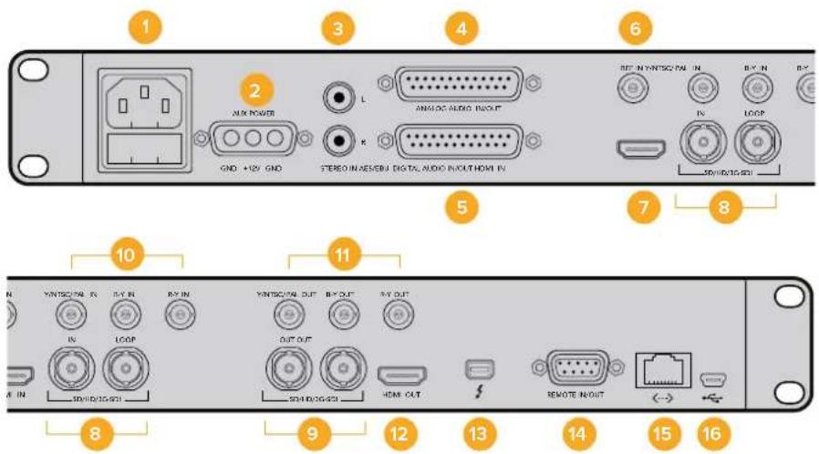
1 Power
1x IEC C14 – For built-in international 90 – 240 volt AC power supply.
2 Power - 12VDC
1x – Military grade port for external battery power or failover redundancy with optional “brick” DC adapter.
3 Analog Inputs, Left and Right
2x RCA Phono – Stereo audio inputs, left & right, unbalanced, line level.
4 Analog Audio In/Out
1x DB-25 – Four channels of balanced analog audio I/O.
5 AES/EBU Digital Audio In/Out
1x DB-25 – Four pairs of digital audio I/O.
6 REF In
1x BNC – Black burst or tri-level reference input.
7 HDMI In
1x HDMI type A – HDMI input
8 SDI In and Input Loop
1x BNC - 3G-SDI input. 1x BNC - 3G-SDI input active loop through.
9 SDI Outputs
2x BNC – Replicated 3G-SDI outputs.
10 Analog Video Inputs
1x BNC - Y/NTSC/PAL component/composite input. 1x BNC - B-Y component input. 1x BNC - R-Y component input.
11 Analog Video Outputs
1x BNC - Y/NTSC/PAL component/composite output.
1x BNC - B-Y component output.
1x BNC - R-Y component output.
12 HDMI Out
1x HDMI type A – HDMI output.
13 Thunderbolt
1x Thunderbolt – Capture/playback computer interface.
14 Remote In/Out
1x DB9 – Sony™ compatible RS-422 deck control port.
15 Ethernet
1x RJ-45 – Connect to a computer running Blackmagic Teranex Setup software to apply settings remotely.
16 USB
1x USB Type B – Connect to a computer running Blackmagic Teranex Setup software to update the internal software.
Teranex 3D
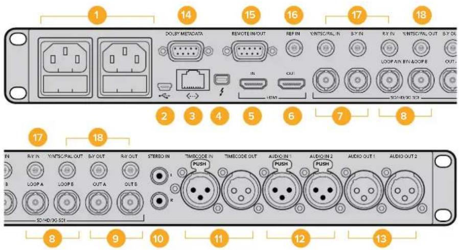
1 Power
2x IEC C14 – For built-in international 90 – 240 volt AC power supplies for failover redundancy.
2 USB
1x USB Type B – Connect to a computer running Blackmagic Teranex Setup software to update the internal software.
3 Ethernet
1x RJ-45 – Connect to a computer running Blackmagic Teranex Setup software to apply settings remotely.
4 Thunderbolt
1x Thunderbolt – Capture/playback computer interface.
5 HDMI In
1x HDMI type A - HDMI input.
6 HDMI Out
1x HDMI type A – HDMI output.
7 SDI Inputs A and B
1x BNC – 3G-SDI input A Usable for single link, encoded 3D input, dual link HD-SDI or dual stream 3D left eye input. 1x BNC – 3G-SDI input B Usable for dual link HD-SDI or dual stream 3D right eye input.
8 SDI Input A and B Loop
1x BNC – SDI input A active loop through. 1x BNC – SDI input B active loop through.
9 SDI Outputs A and B
1x BNC - 3G-SDI output A. Single link output. Usable for dual link HD SDI or dual stream 3D left eye output.
1x BNC – 3G-SDI output B. Replicated Single link output. Usable for dual link HD SDI or dual stream 3D right eye output.
10 Analog Inputs, Left and Right
2x RCA Phono – Stereo audio Inputs, left and right, unbalanced, line level.
11 LTC Timecode In/Out
1x XLR – Timecode Input. 1x XLR – Timecode Output.
12 Analog/AES-EBU Audio In
2x XLR – Two channels of balanced analog audio in or two pairs of AES digital audio in, user selectable.
13 Analog/AES-EBU Audio Out
2x XLR – Two channels of balanced analog audio out or two pairs of AES digital audio out, user selectable.
14 Dolby Metadata
1x DB9 – Dolby metadata support using RS-485.
15 Remote In/Out
1x DB9 – Sony™ compatible RS-422 deck control port.
16 REF In
1x BNC – Black burst or tri-level reference input.
17 Analog Video Inputs
1x BNC - Y/NTSC/PAL component/composite input.
1x BNC - B-Y component input. 1x BNC - R-Y component input.
18 Analog Video Outputs
1x BNC - Y/NTSC/PAL component/composite output.
1x BNC - B-Y component output.
1x BNC - R-Y component output.
Changing Settings
There are two different ways you can change settings on your Teranex processor. You can use the front control panel, or the Blackmagic Teranex Setup software. This section will show you how to use the control panel, or the setup software, to change settings on your Teranex processor.
Changing Settings using the Front Control Panel
Changing settings with the built in control panel is very easy! Once you know the basic principles behind a conversion, all other conversions will become intuitive.
To set a conversion, the first thing to do is set your input and confirm the input signal.
Setting your Input
1 Press the 'in' button on the left side of the control panel. The button will illuminate when selected.

Press the 'in' button to display the video input format. In this example, the format is 1080i50 via SDI with embedded audio.
2 Using the 'video' buttons, select the SDI, HDMI, analog or optical video input.
The inputs available will depend on your Teranex model. When your input is selected, you will see the image displayed on the built in LCD and your Teranex will automatically detect the input format and illuminate all the corresponding buttons, including format and frame rate. The 'frame' button will also illuminate to show you whether your input format is progressive, interlaced or progressive segmented frame.
NOTE If selecting analog video on Teranex 2D or 3D, confirm component or composite video on the LCD by turning the rotary knob. On Teranex AV, pressing the SDI button more than once will alternate between the two rear panel SDI inputs, SDI 1 and SDI 2. On the first button press, the LCD will momentarily display which SDI input is currently selected. If you press SDI again within 5 seconds, the Teranex AV will switch to your other SDI input signal.
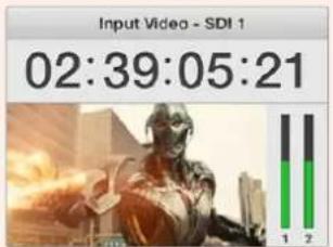

When selecting between the 2 SDI sources on Teranex AV, the LCD will momentarily display which input you have selected.
3 Using the 'audio' buttons, select the embedded, AES, or analog audio input. If selecting analog, confirm your connection as either 'XLR', 'DB25' or 'RCA' to let your Teranex know you want analog audio from the XLR connectors, DB25 connector or the RCA HiFi line input connectors.
Setting your Output
After setting your input, you can now change your output settings for your desired conversion.
1 Press the 'out' button on the left side of the control panel.
2 Select the video 'format' you want to convert to.
3 Choose the 'frame' line mode you want. For example, progressive, interlaced or progressive segmented frame.
4 Choose the desired frame 'rate'.
TIP Buttons with two options, for example the 29.97 and 30 frame rate, alternate with each press of the button.
5 Now set the 'aspect' ratio you want.
Your converted video will now appear on the LCD and is available on all relevant video outputs. You can improve the quality of your conversion by making adjustments to the 'proc amp' and 'video' settings, such as noise reduction, clean cadence, color correction, sharpness, and more.
Refer to the 'Teranex processor settings' and 'conversion workflows' sections for more information about all of the settings on your Teranex and how they work together.

Press the 'out' button and select a format to convert to. In this example, the conversion is set to: 720p50, embedded SDI and HDMI audio, plus analog audio.
Control Panel Overview
This section contains a general overview of all the buttons and features on your Teranex processor's front control panel.
Everything you need to set up your conversions and monitor their status is right there in front of you. Use the control panel LCD, soft menu buttons and rotary knob to navigate through the menus and make your selections. For example, when setting timecode, the cursor is moved forward or backward through the timecode register using the soft menu buttons. Timecode digits are adjusted using the rotary knob. Pressing the rotary knob returns parameters to their default value.
Program your conversion settings by pressing the buttons on the control panel. Buttons are illuminated so you can quickly check the status of your audio and video connections and output settings.
Explore the Teranex menus and experiment with conversion workflows. You'll find examples of common workflows in the 'Conversion Workflows' section.
Some minor features will differ based on the model you are using, but the principles for how they work are the same.
Below is an overview of control panel features.
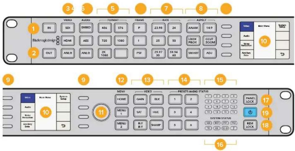
1 IN
Press to display current input settings.
2 OUT
Press to display and change current output settings.
3 VIDEO
Press to select video input type, and displays all video outputs.
4 AUDIO
Press to select audio input type, and displays available audio outputs.
5 FORMAT
Press to select the video output format, and displays the video input format.
6 FRAME
Press to select the video output frame type, and displays video input frame type.
7 RATE
Displays video input frame rate as frames or fields per second. Press to select video output rate.
8 ASPECT
Press to select video input and output aspect ratio settings.
9 SOFT MENU BUTTONS
Press to navigate the LCD menus and apply settings.
10 LCD
Displays the video input and output, and menu settings.
11 ROTARY KNOB
Turn to adjust menu settings. Press to return settings to default.
12 MENU
Press to toggle the LCD between main menu and live video. 'menu 1' and 'menu 2' are programmable as menu page shortcuts. Press and hold to program them.
13 VIDEO
Press to activate video proc amp settings.
14 PRESETS
Press to save or recall custom system configurations.
15 AUDIO STATUS
Displays available input and output audio channels.
16 SYSTEM STATUS
Displays input, output and control status information.
17 PANEL LOCK
Press and hold to lock the control panel to prevent accidental changes. Press and hold to unlock.
18 REM LOCK
Press and hold to prevent access by Teranex Setup remote users. When active, button will turn red. Remote users will see a pop up stating that remote lock is set on the device. Press and hold to unlock.
19 POWER
Press to power on. Press and hold to power off.
Presets
Use the six 'preset' buttons to save and recall your conversion settings. Presets may also be saved, recalled and given descriptive names via the Blackmagic Teranex Setup utility.
Presets wil save all operating parameters of your Teranex for later recall. For example, you could store customized proc amp or aspect ratio settings for instant recall at the moment they are needed in your production. Or, you could save special timecode, closed caption or audio channel mapping configurations for easy repetitive use day after day.
- To SAVE a preset:
Hold the desired 'preset' button for three seconds. The button flashes to indicate the preset was saved and remains illuminated until a setting is adjusted.
- To RECALL a preset:
Press the desired 'preset' button and select 'recall' using the soft menu button. Once recalled, the 'preset' button will illuminate until settings are changed.
![graph TD A["PreSETS"] --> B["1"] A --> C["2"] A --> D["3"] A --> E["4"] A --> F["5"] A --> G["6"] H["Recall preset 1?"] --> I["Cancel"] H --> J["Recall"]](/content/2026/05/812948/images/c981a77a653b4caf752bdb868e1936692b4eeee7068c56d949e3cf11521c1ab2.jpg)
The Preset buttons are used to easily save and recall conversion settings.
TIP Depending on the preset settings, recalling a preset may momentarily disrupt the output video and audio. An example would be a format conversion preset. A preset that only changes 'proc amp' or 'aspect ratio' settings will not typically cause a loss of output. Be sure to test your presets prior to using them.
Audio and System Status LEDs
While performing your conversions, keep an eye on the status LEDs. Illuminated LEDs display signals and communications that are present. For example, indicators tell you which channels contain audio, what power connections are being used, if an external reference signal is present and more. The maximum number of channels supported for each audio type is as follows:
Audio Type Teranex 2D Teranex 3D Teranex AV Teranex Express
| Embedded 16 16 16 16 | |||
| AES/EBU 8 4 4 0 | |||
| Analog 4 2 | 2 | 0 |
System Status LEDs indicate the following when illuminated:
| VID | Input video is present |
| REF | External Reference is selected and External Reference input is present |
| PS1 | Power Supply 1 is operational |
| PS2 | Power Supply 2 is operational, For Teranex 2D and Teranex 3D only |
| TC | Timecode is present in input or output video |
| CC | Closed Captions are present in input or output video |
| <--> | Ethernet communication is present |
| ThunderboltTM communication is present. For Teranex 2D and Teranex 3D only |
The 'audio', 'timecode', and 'close caption' status lights show the presence of these parameters in either the input or output video, depending on the selection of 'in' or 'out'.

Status LEDs are located on the right side of the control panel.
Connecting to a Network
Connect your Teranex processor to your network by plugging a standard CAT-5 network cable into the Ethernet port on the rear panel. Connect the other end of the cable to your network.
By default, your Teranex is configured to automatically acquire a network address. You may change the network settings via the front panel 'system setup' menu. Press the 'home' button on the front panel, select 'system setup' and then the 'Ethernet' menu via the LCD soft buttons. Make the necessary adjustments to your network settings using the menus. Details for the 'Ethernet' menu are provided in the 'System Setup Menu Settings' section in this manual.
Plugging into your network lets you control your Teranex from a computer using the Blackmagic Teranex Setup software. This is helpful if you need to control your Teranex from a separate location, away from the built in control panel.
Changing Settings using Blackmagic Teranex Setup
The Blackmagic Teranex Setup utility offers an intuitive way to view the status of your Teranex Processor and provides remote control from any location on your Ethernet network. This convenient application lets you control your Teranex remotely, away from the front panel.

All your conversion settings can be set remotely using Blackmagic Teranex Setup.
Getting to Know the Interface
When you launch Blackmagic Teranex Setup, you'll first see the login pane. From here you can see all your connected Teranex Processors on your network, and you can add more Teranex Processors if you need to. Open the setup utility by clicking on the 'settings' icon below the name of your Teranex Processor.
Resizing the Interface
Click and drag the bottom right corner of the login pane to proportionally resize the interface to best fit your screen size. Alternatively, drag a window edge to resize either vertically or horizontally.
Selecting a Teranex Processor
The Teranex Setup utility will automatically locate your Teranex processor on your Ethernet network and will display it by model name in the log in pane. If more than one Teranex Processor is found, each will be displayed in a separate window. Simply click the arrows in the right and left screen margins to select the desired processor, then click the icon below the processor's name to establish a connection.
If your Teranex Processor did not automatically appear, you can add the unit manually using its IP address. The IP address of your Teranex Processor can be found via the unit's front panel in the 'system setup menu'. If you need to establish a new IP address, either static or via DHCP, this can also be done from the front panel. Please refer to the 'system setup menu' section of this manual for details.
To add a Teranex Processor using Teranex Setup:
1 Press the + button at the bottom left corner of the login pane to add a device.
2 Type in the IP address and press 'add'.
3 The Teranex Processor will appear as another controllable device on your network.
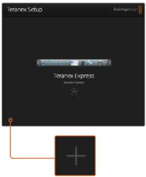

To manually add a Teranex Processor, click the “+” icon on the login pane to open the 'Add a Teranex' window, then enter the IP address of your Teranex Processor.
Menus and Buttons
Most of the remote control functions and parameters in the interface are very intuitive, especially if you are familiar with the front panel operation of the Teranex Processors.
Function Page Bar
Setup and operational controls are separated by function into six pages.
Setup
Selection of video and audio input sources, output video format, external reference and other functions. Unlike the front panel mode of operation, a change of output format is immediately processed and does not require confirmation.
Processing
Access to Video Proc Amp and Color Correction controls, as well as noise reduction and other advanced functions.
Aspect
Choice of aspect ratio, including fixed aspect ratios, variable aspect ratio controls and choice of color fill for PBOX/LBOX aspect ratios.
Data
Ancillary data parameters, including timecode, closed captions and video indexing.
Audio
Audio gain, delay and mapping functions.
Configure
The configure tab displays the name and IP address of the Teranex you are controlling. You can assign a unique name to the unit so you can identify it when you have multiple Teranex units in your system. Simply click in the 'name' field and enter a new name for the device. The name will be seen when you are selecting a Teranex via the Teranex Setup utility and will also be displayed in the utility's header once connected. You can also assign descriptive names for each preset to make it easier to identify the owner, purpose or settings saved in the preset.

Slider Adjustments
To make adjustments, click and drag a slider with your mouse. Another way to adjust a slider is to use the directional keys on your keyboard. The 'up' and 'right' arrows will increment the slider by 1 unit, while the 'left' and 'down' arrows will decrement the value. You can also click in the value box to enter a slider value directly. When needed, you can simultaneously reset all parameters within a section to their default values by clicking the circular back arrow icon.

Settings Menu Using the Gear Icon
Clicking on the 'settings gear' icon reveals the settings menu used for remotely locking the front panel and saving or recalling presets. You may also save the current Teranex settings to a computer or load settings into a Teranex.
Panel Lock via Remote Control
You can remotely lock the Teranex front panel to prevent accidental changes by someone operating the front panel locally. Click on Panel Lock/Unlock in the gear menu to lock or unlock the front panel.
The Panel Lock button on the front panel will turn red when locked. When operating the unit locally, you can override this feature by disabling the panel lock, however caution should be exercised as the unit may be in use by another operator.
Saving and Recalling Presets
There are six presets available in your Teranex. The settings menu lets you save and recall them as needed. Click 'save preset' or 'recall preset', choose the desired 'preset' number and confirm your selection in the dialog box. In the 'configure' tab, you can assign descriptive names for each preset to make it easier to identify the owner, purpose or settings saved in the preset.
Using an External Computer to Save or Recall Current Settings
Through the Teranex Setup utility, you can save the current settings of your Teranex to a file on your computer and recall them later. This feature can also be used to quickly transfer a Teranex configuration from one Teranex to other units within your facility.
Save Current Settings:
This command will export the current settings of your Teranex to a special '.tnx' settings file on your computer. Click on the 'settings gear' icon; click 'save preset' then 'save current settings.' A 'save settings' dialog box will open and prompt you to name the file and choose the desired folder in which to save it for future use. The file will automatically be given an extension of '.tnx.'
Recall Current Settings:
This command enables you to load a previously saved '.tnx' settings file from your computer to your Teranex. Make sure that you are connected to the desired target Teranex on your network. Click on the 'settings gear' icon; click 'recall preset,' then 'recall current settings.' A 'recall settings' window will open on your computer. Locate the desired '.tnx' settings file, click 'open' and the settings will immediately upload to your Teranex.


Click the 'settings gear' icon to reveal the menu. Select the desired function from nested menu.
Aspect Ratio Conversions
A conversion table is provided so you can easily see how each aspect ratio setting will appear in your conversion. This is a helpful reference tool so you can visually identify each setting and make your selection faster.
| Up Conversion Input 4:3 Output 16:9 | |||
| PBOX | Displays a 4:3 SD image inside an HD 16:9 frame. Black bars feature on the sides. | ||
| Pillarbox |  | 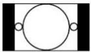 | |
| ZOOM |  |  | Zooms into an SD 4:3 image until it completely fills the HD 16:9 frame. A portion of the top and bottom is lost. |
| 14:9 |  | 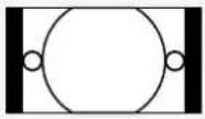 | A compromise between Pillarbox and Zoom. Minimal black bars with a slight crop on the top and bottom. |
| SMART | 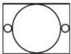 |  | Incrementally stretches the sides to fit 16:9 without distorting the main action of the 4:3 image. |
| ANAM | Horizontally stretches the 4:3 SD image into a 16:9 HD frame. | ||
| Anamorphic |  |  | |
| Down Conversion Input 16:9 Output 4:3 | |||
| LBOXLetterbox |  | 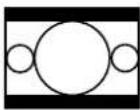 | Scales the entire 16:9 HD image into a 4:3 SD frame leaving black bars on the top and bottom. |
| ANAMAnamorphic |  |  | Horizontally squeezes the 16:9 HD image into a 4:3 SD frame. |
| CCUTCenter Cut | 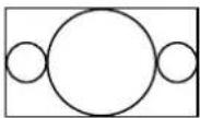 |  | Cuts a 4:3 SD frame from the 16:9 HD image. |
| 14:9 | 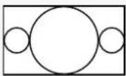 | 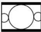 | A compromise between Letterbox and Center Cut. Minimal black bars with a slight edge crop. |
.Widescreen 16:9 SD Conversion to 4:3 SD
While most standard definition programming utilizes a 4:3 aspect ratio, some SD sources may have been recorded in widescreen 16:9. To process SD widescreen inputs properly, the Teranex Processor must be configured to recognize the source as a 16:9 signal.
1 Press the 'in' button on the front panel.
2 In the 'aspect' section, press the 'lbox' button to define your SD input as 16:9 widescreen.
3 Press the 'out' button on the front panel.
4 To output a letterbox version of your widescreen SD source, press the 'lbox' button.
To output a center cut from the your widescreen SD source, press the 'ccut' button.
| SD to SD Conversion | Input is Widescreen SD Output 4:3 | ||
| Input LBOX with Output LBOX |  |  | Scales the entire 16:9 SD image into a 4:3 frame leaving black bars on the top and bottom. |
| Input LBOX with Output CCUT |  |  | Cuts a 4:3 SD frame from the 16:9 SD image. |
4:3 Letterbox SD Conversion to 16:9 SD or HD
A 4:3 standard definition source with an letterboxed 16:9 image can be converted to a full 16:9 output aspect ratio by extracting the 16:9 letterbox and expanding it to a full 16:9 image. The output format can be SD or HD in the Teranex 2D or 3D, as well as Ultra HD in Teranex AV and Teranex Express.
1 Press the 'in' button on the front panel.
2 In the 'aspect' section, press 'ccut'.
3 Press the 'out' button on the front panel and select the desired output video format.
4 In the 'aspect' section, press 'ccut' to output a full 16:9 image. For an SD output, the front panel LCD will display an anamorphic 4:3 image. For HD formats, the image will be 16:9.
4:3 LBOX to 16:9 Conversion
Input CCUT with Output CCUT
Input is Letterbox SD Output 16:9

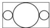
Expands the 16:9 letterbox to a full 16:9 aspect ratio
Conversion Workflows
This section of the manual demonstrates the set up workflows for the main conversions you can perform with your Teranex Processor. All conversions such as standards conversion, up, down and cross conversion, follow the same general set up using the front control panel. You will also see how to save and recall presets for frequently used conversions and how to set cadence settings so you can clean or remove cadence in material using 3:2 pull down.
TIP When setting up a conversion, the status LEDs on the control panel let you monitor exactly what signals are present. You can find more information in the 'Audio and System Status LEDs' section.
Up Conversion
Up Conversion is the process of converting your video to a higher resolution. For example, you may need to insert an NTSC SD source into an HD production. The NTSC clip can be converted to many 720 and 1080 HD output formats and frame rates, depending on your project's requirement. Teranex processors employ high quality de-interlacing and up conversion algorithms, assuring outstanding results. In this example, 486i59.94 component analog video is converted to 1080p29.97 using zoom aspect ratio and RCA analog audio inputs on the Teranex 2D or 3D.
Power your Teranex Processor and connect your inputs and outputs.
Setting your Input
1 Press the 'in' button on the control panel and select 'anlg' video. The 'analog input' menu will be displayed on the LCD.
2 Using the rotary knob, select 'component' as your analog input type. Press the 'in' button to display your input video on the LCD. Teranex automatically detects the input format and illuminates the corresponding buttons on the control panel.
3 Press the 'anlg' audio button. Using the rotary knob, select RCA as your analog audio input type.
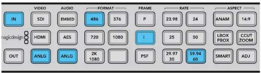
Pressing the IN button displays the input format on the control panel buttons. In the above illustration, the input format is 486i59.94 via analog component with analog audio.
Setting your Output
1 Press the 'out' button on the control panel. On the Teranex 2D, all output buttons will be illuminated blue. On the Teranex 3D, the 'embed' audio button will be blue. Select the 'AES' or 'anlg' button. AES/EBU and analog audio outputs share the XLR connectors. On the Teranex Express, the 'embed' audio button will be blue.
2 Press the '1080' button. Select the 'p' button for progressive output, and the '29.97/30' button to select your frame rate. The format, frame and rate buttons are now illuminated green, ready for you to accept your conversion set up or make changes.
3 Using the soft menu buttons, select 'change'. The output video is now displayed on the LCD and sent to all output connectors. The buttons will also illuminate blue to confirm your settings.

Press the OUT button to select your output settings. In the above illustration the output is set to 1080p29.97 with pillarbox aspect ratio.
Setting your Aspect Ratio
Press the 'ccut/zoom' button to set your aspect ratio to 'zoom'.
Your Teranex Processor is now ready to up convert your video.
![graph TD A["ASPECT"] --> B["ANAM"] A --> C["LBOX PBOX"] A --> D["CCUT ZOOM"] A --> E["SMART"] A --> F["ADJ"] G["ASPECT"] --> H["23.98 24"] G --> I["25 50"] G --> J["29.97 30"] G --> K["59.94 60"] G --> L["SMART"] G --> M["ADJ"] N["ASPECT"] --> O["24:9"] N --> P["CCUT ZOOM"]](/content/2026/05/812948/images/b34efdb00df2b12475dfb7e658425d64b0f5c347bb4e224e7aad516f9910f0f4.jpg)
Aspect ratios are set using the Aspect buttons on the control panel.
TIP For information on the types of aspect ratio settings and how they appear, refer to "Aspect Ratio Conversions" on page 23 and "Video Menu Settings" on page 35.
Up Conversion to Ultra HD using Teranex AV and Teranex Express
The Teranex AV and Teranex Express models support up conversion to Ultra HD and down conversion from Ultra HD. Both models feature 12G-SDI connections that support multi rate switching between 12G-SDI, 6G-SDI, 3G-SDI, regular HD-SDI and standard definition SDI. This means you can convert between SD, HD and Ultra HD formats easily.
In this example, 1080i59.94 SDI input video is being converted to Ultra HD 2160p59.94 with embedded audio.
Power your Teranex processor and connect your inputs and outputs.
Setting your Input
1 Press the 'in' button on the Teranex control panel and select 'SDI' video. Your Teranex will automatically detect the input format, display the input video on the LCD and illuminate the corresponding buttons.
2 'Embed' will be illuminated as the audio input type.

Pressing the IN button displays the input format on the control panel buttons. In the above illustration, the Input format is 1080159.94 via SDI with embedded audio.
Setting your Output
1 Press the 'out' button on the control panel. The 'SDI' and 'embed' audio buttons will be illuminated blue. If the optional optical fiber module is installed, the 'opt' button will also be blue.
2 Press the 'Ultra HD' button. Select the 'p' button for progressive output, and the '59.94/60' button to select your frame rate. The format, frame and rate buttons are now illuminated green, ready for you to accept your conversion set up or make changes.
3 Using the soft menu buttons, select 'change'. The output video is now displayed on the LCD and sent to all output connectors. The buttons will also illuminate blue to confirm your settings.

Press the OUT button to select your output settings. In the above illustration the output is set to Ultra HD 2160p59.94.
Setting your Aspect Ratio
The HD to Ultra HD up conversion in the above example maintains a 16:9 aspect ratio, so no aspect ratio buttons will be illuminated. However, the 'adj' adjustable aspect ratio function is always available when converting HD to Ultra HD if you wish to make any manual aspect ratio adjustments.
Your Teranex Processor is now ready to up convert your HD video to a 12Gb/s UltraHD single link output via OUT A. If you need dual link 6Gb/s output instead, select this mode via the Dual Link Output menu and use outputs A and B for 6 Gb/s dual link UltraHD connections.
Down Conversion
Down Conversion allows you to convert your video to a lower resolution. For example, you may need to distribute a PAL SD version of a 1080p25 HD program master to a client. Once again, high quality de-interlacing, down-sampling and anti-aliasing algorithms will assure outstanding down conversion results. In this example, 1080p25 video via SDI is converted to 576i50 PAL with letterbox aspect ratio. Audio is embedded in the input SDI signal.
Power your Teranex Processor and connect your inputs and outputs.
Setting your Input
1 Press the 'in' button on the control panel and select 'SDI' video. Teranex will display the input video on the LCD, automatically detect the input format and illuminate the corresponding buttons.
2 Select 'embed' as the audio input format.

Pressing the 'in' button displays the input format on the control panel buttons. In the above illustration, the input format is 1080p25 via SDI with embedded audio.
Setting your Output
1 Press the 'out' button on the control panel. On the Teranex 2D, all output buttons will be illuminated blue. On the Teranex 3D, the 'embed' audio button will be blue. Select the 'AES' or 'anlg' button. AES/EBU and analog audio outputs share the XLR connectors.
2 Press the '576' button. The button will illuminate green. Note that the 'I' button and the '50' button are also illuminated green. This is because interlaced video and 50 fields per second are the only selections available for a PAL 576 output.
3 Using the soft menu buttons, select 'change'. The output video is now displayed on the LCD and sent to all output connectors. The buttons will also illuminate blue to confirm your settings.

Press the 'out' button to select your output settings. In the above illustration the output is set to 576i50 with letterbox aspect ratio.
Setting your Aspect Ratio
Press the 'lbox/pbox' button to set your aspect ratio to letterbox. Your Teranex Processor is now ready to down convert your video.

4:3 Ratio Display16:9 Ratio Image
Setting the LBOX/PBOX button on your SD output fits the 16:9 image inside the 4:3 frame. The 4:3 conversion will have black bars top and bottom and the correct widescreen geometry will be maintained.
TIP For more information on aspect ratio conversion refer to "Aspect Menu" on page 35 and "Aspect Ratio Conversions" on page 23.
Cross Conversion
Cross Conversion allows you to change the video resolution and/or aspect ratio of your program material. Cross conversions between 1080 and 720 HD formats are accomplished using a high quality de-interlacing algorithm that permits all conversions to be performed in the progressive domain. In SD formats, aspect ratio conversions between 4:3 and 16:9 are also easy to perform. In this example 486i59.94 with 16:9 aspect ratio is cross converted to letterbox 4:3 via SDI with embedded audio.
Power your Teranex Processor and connect your inputs and outputs.
Setting your Input
1 Press the 'in' button on the control panel and select 'SDI' video. Teranex will display the input video on the LCD, automatically detect the input format and illuminate the corresponding buttons.
2 Select 'embed' as the audio input format.

Press the 'in' button to see the format of the video signal that you are converting. In this example, the format is 486159.94 over SDI with embedded audio.
Setting your Input Aspect Ratio
Press the 'lbox' button to select letterbox, indicating that the input aspect ratio is 16:9.
Setting your Output
1 Press the 'out' button on the control panel. On the Teranex 2D, all output buttons will be illuminated blue. On the Teranex 3D, the 'embed' audio button will be blue. Select the 'AES' or 'anlg' button. AES/EBU and analog audio outputs share the XLR connectors. On Teranex AV and Teranex Express, the 'embed' audio button will be blue.
2 Press the '486' button. The button is illuminated green. Note that the 'I' button and the '59.94/60' button are also illuminated green. This is because interlaced video and 59.94 fields per second are the only selections available for an NTSC 486 output.
3 Using the soft menu buttons, select 'change'. The output video is now displayed on the LCD and sent to all output connectors.
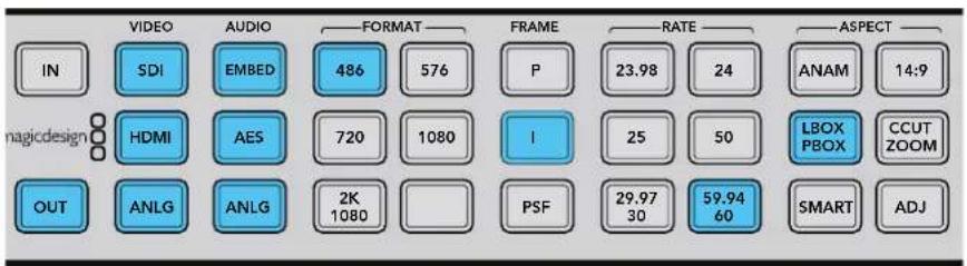
Press the 'out' button to select your output settings. In the above illustration the output is set to 486159.94 with letterbox aspect ratio.
Setting your Output Aspect Ratio
Press the 'lbox/pbox' button to set your aspect ratio to letterbox. Your Teranex Processor is now ready to cross convert your video.
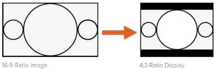
Setting the LBOX/PBOX button on your SD output fits the 16:9 image inside the 4:3 frame. The 4:3 conversion will have black bars top and bottom and the correct widescreen geometry will be maintained.
TIP For more information on aspect ratio conversion refer to "Aspect Menu" on page 35 and "Aspect Ratio Conversions" on page 23.
Standards Conversion
Standards Conversion, also known as 'frame rate conversion', is the process of converting one video frame rate to another, such as converting NTSC at 59.94 fps to PAL at 50 fps.
The powerful Teranex linear interpolation algorithm analyzes pixels between and within frames, calculating new pixels in real time to create the new output frame rate. In this example 1080i59.94 video is converted to 1080i50 via SDI with embedded audio.
Power your Teranex Processor and connect your inputs and outputs.
Setting your Input
1 Press the 'in' button on the control panel and select 'SDI' video. Teranex will display the input video on the LCD, automatically detect the input format and illuminate the corresponding buttons.
2 Select 'embed' as the audio input format.
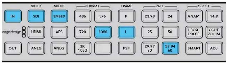
Pressing the 'in' button displays the input format on the control panel buttons. In the above illustration, the input format is 1080:59.94 via SDI with embedded audio.
Setting your Output
1 Press the 'out' button on the control panel. On the Teranex 2D, all output buttons will be illuminated blue. On the Teranex 3D, the 'embed' audio button will be blue. Select the 'AES' or 'anlg' button. AES/EBU and analog audio outputs share the XLR connectors.
2 Press the '1080' button. The button will illuminate green. Select the 'l' button for interlaced output and the '50' button to set the frame rate. These buttons will also illuminate green.
3 Using the soft menu buttons, select 'change'. The output video is now displayed on the LCD and sent to all output connectors. The buttons will also illuminate blue to confirm your settings.

Press the 'out' button to select your output settings. In the above illustration the output is set to 1080i50.
Setting your Frame Rate Conversion Aperture
When converting frame rates you'll need to set the appropriate frame rate aperture.
Select your settings from 0 'Drama' to 3 'Sport' depending on the amount of motion in your video. These settings are adjusted using the soft menu buttons and rotary knob.
1 Press the 'home' button.
2 Using the soft menu buttons, select Video>Advanced>FRC Aperture.
3 Using the rotary knob, select the aperture setting most suited to your video.

Main Menu>Video
![graph TD A["Color"] --> B["Video"] C["Clip"] --> B D["Aspect"] --> E["Test Patterns"] D --> F["Advanced"] G["Setup"] --> H["→"]](/content/2026/05/812948/images/1bd1c0dab36a3d7364315806e686472e03182188e40ad0a444510eab1ae99f66.jpg)
Video>Advanced Menu

Advanced Menu>FRC Aperture
Setting your Aspect Ratio
When up, down or cross converting between HD and Ultra HD, the aspect ratio will always be 16:9, so no aspect ratio buttons will be illuminated. However, the 'adj' adjustable aspect ratio function is always available when converting within the same format if you wish to make any manual adjustments.
When converting from one format to another, for example SD to HD, other aspect ratio settings will become available. Your Teranex Processor is now ready to convert your 1080i59.94 video to 1080i50.
TIP For more information on aspect ratio conversion refer to
"Aspect Menu" on page 35 and "Aspect Ratio Conversions" on page 23.
Cadence Removal
Cadence Removal involves the removal of the 3:2 pulldown sequence. 3:2 pulldown is applied when a telecine transfers film at 24 frames per second to video at 59.94 fields per second. Your Teranex processor will remove cadence automatically when converting video with a 3:2 pulldown to 24 frames per second.

Cadence Removal is applied automatically when converting from an NTSC frame rate to a film frame rate. For example, 59.94fps to 23.98fps.
Clean Cadence
Clean Cadence in the Teranex 2D and 3D removes broken, non standard and mixed cadences and creates a clean 3:2 pulldown. A 3:2 cadence is found in 59.94 program material, so clean cadence is only available when working with 59.94 frame rates. In this example, we will perform a cross conversion to clean the cadence on a 1080i59.94 video signal via SDI with embedded audio.
TIP For information on advanced clean cadence settings, refer to "Advanced Menu" on page 43.
Power your Teranex and connect your inputs and outputs.
Setting your Input
1 Press the 'in' button on the control panel and select 'SDI' video. Teranex will display the input video on the LCD, automatically detect the input format and illuminate the corresponding buttons.
2 Select 'embed' as the audio input format.
Setting your Output
1 Press the 'out' button on the control panel. All active video output buttons are illuminated blue.
2 Press the '1080' button. The button is now illuminated green. Select the 'I' button for interlaced output and the '59.94/60' button to set the frame rate. These buttons will also illuminate green.
3 Using the soft menu buttons, select 'change'. The output video is now displayed on the LCD and sent to all output connectors. The buttons will also illuminate blue to confirm your settings.
4 In this example aspect ratio is locked to 16:9. However, if you wish to adjust it manually press the 'adj' button and adjust your aspect ratio settings using the soft menu buttons and LCD.
5 Press the 'home' menu button, then select Video>Advanced>Clean Cadence. Use the rotary knob or soft button to set clean cadence to 'on'. The 1080i59.94 output format will now contain a clean 3:2 cadence. Remember to set clean cadence to 'off' after completing your conversion.
![graph TD A["Color"] --> B["Video"] B --> C["Proc Amp"] D["Clip"] --> E["Test Patterns"] F["Aspect"] --> G["Advanced"] H["Setup"] --> I["→"]](/content/2026/05/812948/images/c9fe41868280fe6197ed0350ea0fef134ee853e33e25d480b18de30d484014d0.jpg)
Main Menu>Video Menu>Advanced
![graph TD A["Clean Cadence"] --> B["Advanced"] B --> C["On"] B --> D["Off"] C --> E["Source Type"] D --> F["FRC Aperture"] G["Scene Detect"] --> H["Off"] I[" "] --> J[" "] K[" "] --> L[" "]](/content/2026/05/812948/images/ae3c07f64588632410ee9bd6ec25fa7fb86676919a228d57b9b54fb60af0d1e5.jpg)
Advanced Menu>Clean Cadence
Setting your Aspect Ratio
The 'adj' adjustable aspect ratio button is available for custom aspect ratio settings.
After all cadence and aspect ratio settings are done, your video will now have a clean cadence applied.
TIP For information on the types of aspect ratio settings and how they appear, refer to "Aspect Ratio Conversions" on page 23 and "Video Menu Settings" on page 35.
Lowest Latency Processing on Teranex AV
A low latency mode is available on Teranex AV that can perform common conversions in much lower latency than regular processing. The lowest latency mode of processing for certain format conversions will run at a latency of 2 frames. This is very useful in live production environments to reduce delays between the live action and the image being displayed on monitors or projectors.
In this example, 1080i59.94 is converted to Ultra HD 2160p59.94 using the Lowest Latency mode in the 'processing' menu.
Power your Teranex AV processor and connect your inputs and outputs.
Select a conversion that supports low latency, then enable low latency mode.
Setting your Input
1 Press the 'in' button on the control panel and select 'SDI' video.
2 Teranex will display the input video on the LCD, automatically detect the input format and illuminate the corresponding buttons.
Setting your Output
1 Press the 'out' button on the control panel. On the Teranex AV, the 'SDI' and 'embed' buttons will be blue.
2 Press the 'Ultra HD' button. The button will illuminate green. Select the 'P' button for progressive output and the '59.94' button to set the frame rate. These buttons will also illuminate green.
3 Using the soft menu buttons, select 'change'. The output video is now displayed on the LCD and sent to all output connectors. The buttons will also illuminate blue to confirm your settings.
Enabling the Lowest Latency Mode
1 Go to the 'System Setup' LCD menu in your Teranex AV, select the 'processing' submenu and then select 'lowest latency.' You can also access this feature via the Setup tab in the Teranex Setup application.
2 The Teranex AV will load the 'lowest latency' configuration for this conversion, which will run at the minimal latency of 2 frames or less. Once selected, your Teranex AV will operate in the lowest latency available for the conversion and features you want to enable.
Audio Embedding
Embedding external analog or AES audio into your SDI or HDMI outputs is possible in the Teranex 2D, Teranex 3D and Teranex AV. Connect your audio source and select the corresponding input on the front panel, either "ANLG" or "AES." The Teranex will embed the audio into your SDI and HDMI outputs.
In the Teranex AV, you may embed audio even if you do not have an active video input. When no video input is detected, the Teranex AV will embed your external audio into internal black or color bars, depending on the selection made in the "No Video Input" menu in the Video Setup menu.
Teranex Processor Settings
Demonstrations are provided in this section to show you how to set your Teranex Processor for each conversion type using the control panel buttons and LCD. Plus you can find out how to use all the settings available to help you maximize the quality of your conversion. For example, setting the FRC aperture to achieve the best motion quality in a standards conversion, or choosing your desired aspect ratio for up or down conversion. With all the different settings available you get many opportunities to improve the quality of your converted video. You can use the clean cadence feature to clean up potential cadence issues, add noise reduction, change video levels and more.
LCD Menu
The LCD menu is controlled by 8 soft buttons used to make your selections. The 8 buttons are called soft buttons because their function changes with each menu displayed.
The rotary knob adjusts parameter values by turning clockwise or counterclockwise. If a parameter 'default' setting exists, press the rotary knob to quickly reset it.
Home Button
The ‘home’ button toggles the LCD between the video display and the main menu.
Menu 1 and Menu 2 Buttons
These buttons save shortcuts to frequently used menu pages and settings.
To store a menu page:
1 Navigate to the menu page you want to save.
2 Press and hold 'MENU 1' or 'MENU 2' for 3 seconds.
The button will illuminate to indicate a saved page. Thereafter, when the button is pressed, the LCD will switch directly to the saved page.

Video Menu Settings
The ‘video menu’ controls settings that adjust your video output, such as color, clipping, aspect ratio and more.
Color Menu
To adjust your Red, Green and Blue Gain settings, turn the rotary knob on each color channel.
- The Range of each color control is -200 to +200.
- The default is 0.

Main Menu>Video
![graph TD A["Color"] --> B["Video"] C["Clip"] --> B D["Aspect"] --> B E["Setup"] --> B B --> F["Proc Amp"] B --> G["Test Patterns"] B --> H["Advanced"] B --> I["→"]](/content/2026/05/812948/images/12c799c3299d825340da060e6a49451f9ea4907da47e8b2ed6e0b8c1598f6414.jpg)
Video Menu>Color
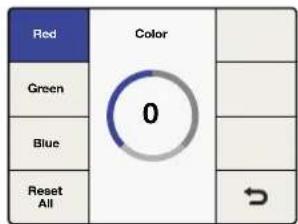
Color Menu>Red
Clip Menu
To adjust luminance and chrominance clipping on your output video, go to Main Menu>Video>Clip. Adjust high and low ranges using the rotary knob.
![graph TD A["Color"] --> B["Video"] C["Clip"] --> B D["Aspect"] --> B E["Setup"] --> B B --> F["Proc Amp"] B --> G["Test Patterns"] B --> H["Advanced"] B --> I["→"]](/content/2026/05/812948/images/9ba7cec899a35d3e05802d924722642b7b1c48eeb83e3c7e9a1edbb1ce231939.jpg)
Video Menu>Clip
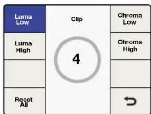
Clip Menu
Aspect Menu
To adjust the aspect ratio settings of your Teranex output video, go to Main Menu>Video>Aspect>Adjust Aspect, or simply press the 'adj' button in the front panel. 'Fill' defines a color for the letterbox or pillar box bars.
![graph LR A["Color"] --> B["Video"] C["Clip"] --> B D["Aspect"] --> B E["Setup"] --> B B --> F["Proc Amp"] B --> G["Test Patterns"] B --> H["Advanced"] B --> I["→"]](/content/2026/05/812948/images/ff43f45bd34e060f90b9797715ddc0787374d6bced72c47656dc387083d8acb2.jpg)
Video Menu>Aspect Menu
| Adjust Aspect | Aspect | Fill |
| Zoom Crop | ||
| ↘ |
Aspect Menu
Adjust Aspect
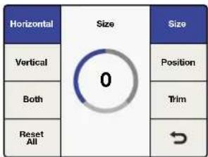
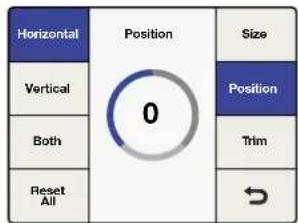
To customize the aspect ratio size, position and trim settings, use the soft menu buttons and rotary knob.
Size
The 'size' setting adjusts the horizontal and/or vertical image size.
The range is approximately -50 to +200 percent.
Position
Position allows you to move the input image within the output frame.
The range of adjustment is dependent on the current image size.
Trim
Trim masks the edges of your input image horizontally and/or vertically.
Horizontal
Used for horizontal sizing, positioning and trimming.
Vertical
Used for vertical sizing, positioning and trimming.
Both
Links horizontal and vertical controls together. For example, when changing the input image size, linking both controls maintains the proper aspect ratio.
Reset All
Press to return all settings to their default values.
Horizontal>Size
![graph TD A["0"] --> B["Horizontal"] A --> C["Vertical"] A --> D["Both"] A --> E["Reset All"] A --> F["Size"] A --> G["Position"] A --> H["Trim"] A --> I["→"]](/content/2026/05/812948/images/1c3d0995ec646c88b1428c60a1b4483b4899c736b6ca9d4c6420e9ecb16a4c4a.jpg)
Horizontal>Trim
Horizontal>Position
Aspect Fill
To define the color of the bars used in pillarbox and letterbox aspect ratios, adjust the 'luminance', and 'cb' and 'cr' chroma values using the rotary knob.
Zoom/Crop
Zoom/crop is used to mask potential video disturbances that may appear at the top, bottom, left or right edges of your source image. This is performed by trimming your conversion slightly. Turning zoom/crop on will instantly zoom the converted image vertically by 3 lines and horizontally by 3 pixels, then crop the image by the same amount. Zoom/crop will not effect your adjustable aspect ratio settings.
![graph TD A["Adjust Aspect"] --> B["Aspect"] B --> C["Fill"] B --> D["Zoom Crop"] B --> E[" "] B --> F[" "]](/content/2026/05/812948/images/2e85b3b380941a7918ca142a2842cfffd82ea34e8821e4c35e65b55d29fdf24c.jpg)
Aspect Menu>Aspect Fill
![graph TD A["Adjust Aspect"] --> B["Zoom Crop"] B --> C["Fill"] B --> D["On"] D --> E["Zoom Crop"] D --> F["Off"] F --> G[" "] G --> H[" "] H --> I[" "]](/content/2026/05/812948/images/4b35a78d012342d1d5bbfd6567fa2bfb7d5f0dbd51322b5652ee0c3134cb38a2.jpg)
Aspect Menu>Zoom/Crop
![graph TD A["64"] --> B["Luma"] A --> C["Fill"] A --> D["Cb"] A --> E["Cr"] A --> F["Reset All"] A --> G["→"]](/content/2026/05/812948/images/3bfa1ce202968c9ecba620a689dd5826336976bbec91d1f34428f771fe72005e.jpg)
Aspect Fill>Luma
Video Setup Menu
The 'video setup' menu lets you define the video parameters of your analog, SDI and HDMI inputs and outputs. The Teranex model you are using determines menu availability.
No Video Input Menu
Use this menu to select black or colorbars to be output when no video input is detected. The default setting is black.
HDMI Output Menu for Teranex AV only
The color space of the HDMI output may be set to YUV or RGB in this menu and via the 'Setup' tab in the Blackmagic Teranex Setup utility.
![graph TD A["Color"] --> B["Video"] C["Clip"] --> B D["Aspect"] --> B E["Setup"] --> B B --> F["Proc Amp"] B --> G["Test Patterns"] B --> H["Advanced"] B --> I["→"]](/content/2026/05/812948/images/033e369d2d8c8d2efd2b5009d1e1687b74839dd329db6932262965d22f258b4f.jpg)
Video Menu>Setup

Video>Setup>No Video Input

Video>Setup>HDMI Output
NOTE: Teranex AV automatically detects the HDMI input color space and switches between YUV and RGB as needed. The HDMI loop output follows the input color space.
Analog Input Video Setup Menu
In the Teranex 2D and 3D Processors, this menu lets you set the analog video input type.
- Component
Sets the analog input BNC connections as component Y, R-Y and B-Y.
- Composite
Sets the analog Y/NTSC/PAL input BNC connector as composite.
The default setting is 'component'.
Analog Output Video Setup Menu
In the Teranex 2D and 3D Processors, this menu lets you set the analog video output type.
- Component
Sets the analog output BNC connections as component Y, R-Y and B-Y.
- Composite
Sets the analog Y/NTSC/PAL output BNC connector as composite.
The default setting is 'component'.
![graph LR A["Color"] --> B["Video"] B --> C["Proc Amp"] D["Clip"] --> E["Test Patterns"] F["Aspect"] --> G["Advanced"] H["Setup"] --> I["→"]](/content/2026/05/812948/images/064ee3b8ef18a45be3fb09fd515208a40f97f1fa23bac9f6ee4d822fdab159b5.jpg)
Video Menu>Setup
| No Video Input | Setup | Video Sampling |
| Analog Input | Component | SDI Output |
| Composite | ||
| Analog Output | ||
Video>Setup>Analog Input
![graph TD A["No Video Input"] --> B["Analog Input"] B --> C["Analog Output"] C --> D["Component"] D --> E["Composite"] E --> F["SDI Output"] F --> G["Output"] G --> H["Output"]](/content/2026/05/812948/images/617d8527fd676d787ab5cb80f1856d5f1d2b6936f325436a1e6a75556a1374a0.jpg)
Video>Setup>Analog Output
Video Sampling Menu for Teranex 3D Processor only
The ‘video sampling’ menu allows selection of the following sampling types for the Teranex 3D Processor.
4:2:2 - YUV
4:4:4 - YUV
4:4:4 - RGB
![graph TD A["Color"] --> B["Video"] C["Clip"] --> B D["Aspect"] --> B E["Setup"] --> B B --> F["Proc Amp"] B --> G["Test Patterns"] B --> H["Advanced"] B --> I["→"]](/content/2026/05/812948/images/f852075e94477a106f62a11fcdef54eaadcbde5d46857ff8e0ba8a100cbc36f9.jpg)
Video Menu>Setup
| No Video Input | Setup | Video Sampling |
| Analog Input | 4:2:2 YUV | SDI Output |
| 4:4:4 YUV | ||
| Analog Output | 4:4:4 RGB | |
Video>Setup>Video Sampling
SDI Output Menu for Teranex 3D Processor only
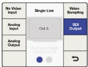
This menu allows you to select between Single Link or HD Dual Link Outputs. Press the Dual Link Output button, or use the front panel knob to toggle between the Single Link and Dual Link output types.
- Single Link SDI supports data rates from 270 Mb/s to 3 Gb/s. In Single Link mode, the Teranex 3D provides redundant SDI outputs on Outputs A and B.
- Dual Link SDI supports Level B 1080p at 3 Gb/s which is 2x 1.5 Gb/s on SDI Outputs A and B. You may use the Video Sampling Menu to choose between 4:2:2 YUV, 4:4:4 YUV and 4:4:4 RGB.
![graph TD A["No Video Input"] --> B["Single Link"] B --> C["Video Sampling"] D["Analog Input"] --> E["Out A"] F["Analog Output"] --> G["Use this for Single Link SD or HD"] H["SDI Output"] --> I["Output"] J["Input"] --> K["Output"]](/content/2026/05/812948/images/9fcdd4252177b9fef3fbd60e8252ab46b7cf4fa6b1553b7983c04385a27f2164.jpg)
Video Menu>Setup>SDI Output>Single Link Output
Video Menu>Setup>SDI Output>Dual Link Output
SDI Output Menu for Teranex Express Processor only
This menu lets you select between single link, dual link or quad HD outputs for your chosen output format. Press the 'SDI output' button, or use the front panel knob to toggle between 'single link', 'dual link' and 'quad HD-SDI' outputs.
- Single Link SDI supports SDI data rates from 270 Mb/s to 12Gb/s. 'Output A' supports single link outputs up to 12Gb/s, while 'output B' supports single link outputs up to 6Gb/s.
- Dual Link SDI supports 3G via 2x 1.5Gb/s, 6G via 2x 3Gb/s, and 12G via 2x 6Gb/s. SDI outputs A and B facilitate dual-link output.
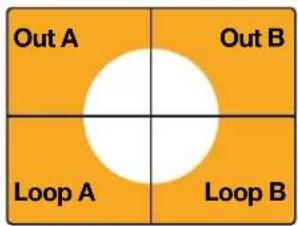
- Quad HD Split in the Teranex Express supports Ultra HD output formats in the square division method of 4x1080p as outlined in SMPTE 435-1. To provide the required four SDI outputs, Teranex Express utilizes the two SDI outputs and repurposes the two SDI Input Loop connectors as outputs.
The quad HD outputs are assigned as follows:
• SDI Output A: Sub image 1
- SDI Output B: Sub image 2
• SDI Input Loop A: Sub image 3
• SDI Input Loop B: Sub image 4

Full Frame Ultra HD Image
Quad HD Split Output
![graph LR A["Setup"] --> B["Aspect"] B --> C["Clip"] C --> D["Color"] D --> E["Video"] E --> F["Proc Amp"] F --> G["Test Patterns"] G --> H["Advanced"] H --> I["→"]](/content/2026/05/812948/images/f0df2880935abd9e60b6d92f1a4137de1a1737f15afb96cf51c0a287b0bc7b5f.jpg)
Video>Setup
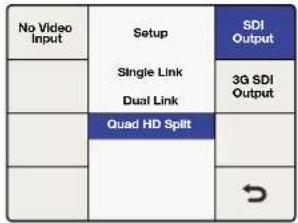
Setup>SDI Output
SDI Output Menu for Teranex AV only
This menu allows you select between single link or dual link outputs for your chosen output format. Press the 'SDI output' button, or use the front panel knob to toggle between 'single link' and 'dual link.'
- Single Link SDI outputs A and B support data rates from 270 Mb/s to 12Gb/s.
- Dual Link SDI supports 3G via 2x 1.5Gb/s, 6G via 2x 3Gb/s, and 12G via 2x 6Gb/s. SDI outputs A and B facilitate dual-link output.

Video>Setup>SDI Output
3G SDI Output Menu for Teranex Express and Teranex AV
This menu lets you change the 3G-SDI output standard to maintain compatibility with equipment that can only receive level A or level B 3G-SDI video.

Video>Setup>3G SDI Output
TIP This setting only applies when outputting 3G-SDI video. For 3G-SDI inputs, 'level A' and 'level B' signals are detected automatically.
Quad SDI Output Menu for Teranex AV only
Teranex AV provides continuous quad SDI outputs via four dedicated BNC connectors when Ultra HD output formats are in use. The BNC output connectors are labeled 'ch A', 'ch B', 'ch C', and 'ch D'.
Teranex AV supports 'quad link' two-sample interleave, or 2SI, and 'quad HD split' square division outputs for Ultra HD p50/59.94/60 output formats. Use the 'quad SDI output' menu below to define the output type you are using.
For Ultra HD p23.98/24/25/29.97/30 formats, only 'quad HD split' is supported, regardless of the setting in the 'quad SDI output' menu.
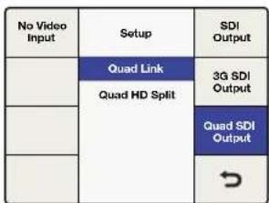
Video>Setup>Quad SDI Output
This diagram represents the difference between 'quad link', where image information is split between four 3G-SDI cables to form a single Ultra HD image, and 'quad HD split', where each of the four HD outputs receives one quarter of the complete image.

Quad Link

Quad HD Split
Proc Amp Menu
Use the 'proc amp' menu to adjust gain, saturation, hue, sharpness and more. The 'proc amp' menu is accessed via the 'video' menu. A quicker way to reach this menu is by pressing one of the 'proc amp' video buttons on the control panel. Turn the rotary knob to adjust your settings.
After adjustment, the associated button will illuminate white to indicate a non-default setting. To reset to its default setting, select the parameter via the 'proc amp' menu or control panel button and then push the rotary knob. To easily return all parameters to their default settings, go to the 'proc amp' menu and select 'reset all'.
Gain
Range: -60 to +60. Default: 0
- Saturate
Range: -60 to +60. Default: 0
- Black
Range: -30 to +30. Default: 0
- Hue
Range: -179 to +180. Default: 0 degrees
R-Y and B-Y
Range: -200 to +200. Default: 0
- Sharp
Range: -50 to +50. Default: 0
- Reset All
Resets all Proc Amp parameters to their default values
![graph TD A["Color"] --> B["Video"] C["Clip"] --> B D["Aspect"] --> B E["Setup"] --> B B --> F["Proc Amp"] B --> G["Test Patterns"] B --> H["Advanced"] B --> I["→"]](/content/2026/05/812948/images/89323ac2cbddac27a0c80fcc19c1006300944031dad0f81a3ee53cf80fdb797f.jpg)
Video Menu>Proc Amp
![graph TD A["Gain"] --> B["Proc Amp"] B --> C["Black"] B --> D["Hue"] B --> E["Sharp"] B --> F["↔"] B --> G["Saturate"] B --> H["R-Y / B-Y"] B --> I["Reset All"]](/content/2026/05/812948/images/2264a91c57c7c9c6402380831dee91752d7ff6f62cdeca9958aab6b19fe450fb.jpg)
Proc Amp Menu>Gain
Test Patterns Menu
The internal test signal generator provides a black output and test patterns. You can add audio test tones via 'output mapping' in the 'audio main menu'. For more information on output mapping, see the 'audio menu settings' section in this manual.
![graph LR A["Color"] --> B["Video"] B --> C["Proc Amp"] D["Clip"] --> E["Test Patterns"] F["Aspect"] --> G["Advanced"] H["Setup"] --> I["→"]](/content/2026/05/812948/images/0a71166ea8361dae91032c077011ef47a223d4a0b9a52f18e3ee6443267257b6.jpg)
Video Menu>Test Patterns

Test Patterns Menu
Below are test patterns available via the 'video>test patterns' menu.

SMPTE 75%.
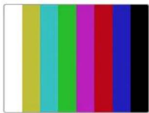
Colorbar 75%.


Res Chart. Grid.
Test Patterns in Teranex AV
In addition to the video test patterns shown above, the Teranex AV includes a menu for pattern motion and an integrated audio test tone menu.
- Test Patterns
Select 'test patterns' to choose the desired video test signal.
- Audio
The 'audio' menu will be grayed out until a video test signal is selected. Select the desired audio frequency using the rotary knob. The tone will be applied to all output audio channels, temporarily overriding any pre-existing audio output mapping.
The original audio output mapping will be restored when the video test pattern or the 'audio' menu is turned off.
- Motion
The 'motion' menu will also be grayed out until a video test pattern is selected. Turn on the 'motion' menu to activate the 'horizontal' control button and adjust the rate of motion, as described below. When the 'motion' menu is turned off, the test pattern will return to its static, full frame position.
- Horizontal: Turn the rotary knob clockwise for left-to-right motion, counterclockwise for right-to-left motion. Three speeds are available in each direction, with a range of -3 to +3. Press the rotary knob to reset the default speed of 0, which will stop the test pattern at the current screen location.
Your Teranex AV will remember the settings in the 'audio' and 'motion' menus when the test pattern is turned off. This allows you to choose your audio tones and/or motion speed and direction in advance, as these settings will be used whenever you turn on your video test pattern. You can also save a test pattern configuration in one of the six system presets for fast and easy recall when needed.
![graph TD A["Color"] --> B["Video"] C["Clip"] --> B D["Aspect"] --> E["Test Patterns"] D --> F["Advanced"] G["Setup"] --> H["→"]](/content/2026/05/812948/images/466ffcd4f6aacaea7b6ea73e630b0cfa3fcdba7fe66388a069793edab621cd11.jpg)
Video>Test Patterns

Test Patterns menu
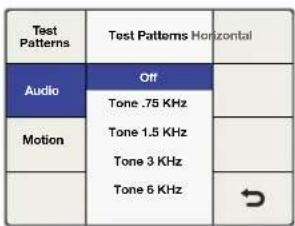
Test Patterns>Audio

Video>Test Patterns>On/Off
![graph TD A["Test Patterns"] --> B["0"] C["Audio"] --> B D["Motion"] --> B E["Horizontal"] --> B](/content/2026/05/812948/images/b9d64e11ce94f7d25ce7c50a396c60932e63f0c6a7a9d9d56d69635df8ba643c.jpg)
Motion>Horizontal Rate
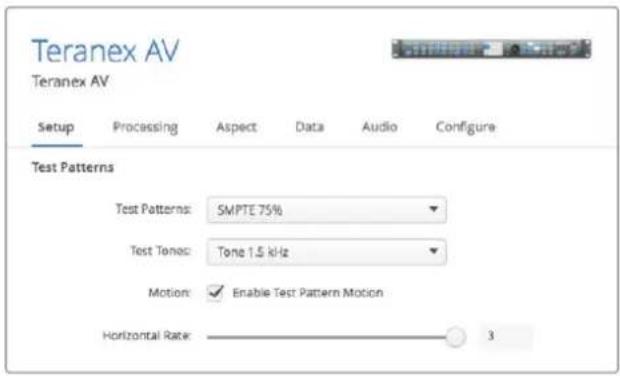
The Setup page in the Blackmagic Teranex Setup utility provides motion control, selection of video test patterns and audio test tones
Advanced Menu
Your Teranex processor provides the following advanced cadence correction features:
Clean Cadence for Teranex 2D and 3D
The clean cadence feature creates a clean 3:2 pull down sequence in your 59.94 output video.
Setting Clean Cadence
Turn 'clean cadence' on or off using the soft menu buttons and rotary knob.
- On
Selects the 'clean cadence' mode
- Off
Selects the 'normal video' mode
The default mode is 'off'
TIP Use the 'clean cadence' mode when you are certain your source material was originated with a 3:2 pulldown sequence, such as film transferred to video by a telecine. If 'clean cadence' is used on video without 3:2 pulldown, unwanted artifacts may be seen.
'Clean cadence' is available for the following format conversions:
486i59.94 to 486i59.94
486i59.94 to 1080i59.94
1080i59.94 to 486i59.94
• 1080i59.94 to 1080i59.94
![graph TD A["Color"] --> B["Video"] C["Clip"] --> B D["Aspect"] --> E["Advanced"] F["Setup"] --> G["→"]](/content/2026/05/812948/images/c1afc9d1bc58d71b5fbfe0eaa76dbe733fe239b9171fb3ff3d3b83bebfdb8a4a.jpg)
Video Menu>Advanced
![graph TD A["Clean Cadence"] --> B["On"] B --> C["Off"] C --> D["Source Type"] E["Scene Detect"] --> B E --> F["FRC Aperture"] G[" "] --> H[" "] I[" "] --> J["→"]](/content/2026/05/812948/images/a66c32f3988d42c141295feb3f5043669df05af66177dfcc98019f40779ab958.jpg)
Advanced Menu>Clean Cadence
Scene Detect
Scene change detection minimizes field blending between cuts for a cleaner looking output. This prevents fields from previous scenes mixing with new scenes.
- On
Enables 'scene cut detection'
- Off
Disables 'scene cut detection'
The default mode is 'on'
Most video is fine with 'scene detect on', but some video sequences may "stutter" due to the momentary change in temporal resolution. Video with a text crawl at the bottom of the picture may show this effect. Be sure to turn 'scene detection off' if you see this "stutter" effect.
![graph TD A["Color"] --> B["Video"] B --> C["Proc Amp"] D["Clip"] --> E["Test Patterns"] F["Aspect"] --> G["Advanced"] H["Setup"] --> I["→"]](/content/2026/05/812948/images/129f584c43741e1b93e87ebbee4b7ce9106e6c25c437cf7266cbb5ef5f4c21bc.jpg)
Video Menu>Advanced
![graph TD A["Clean Cadence"] --> B["On"] B --> C["FRC Aperture"] D["Scene Detect"] --> E["Off"] E --> F["→"]](/content/2026/05/812948/images/cf92719172471e7f7836e8a26487d8a53a94ff3bf29e4070df34f52a63af1f68.jpg)
Advanced Menu>Scene Detect
Setting Source Type
'Source type' sets processing based on the type of input video being received. The default mode is 'auto', but if you want to select 'film' or 'video' modes, you can select them in the menu.
- Auto
This mode will look for film and video based material and select the appropriate processing algorithm. This mode should be used in most instances.
Film
Select this mode when you're sure the source material contains a 3:2 pulldown cadence.
- Video
Select this mode when you're sure the source material does not contain a 3:2 pulldown cadence.
Frame Rate Conversion Aperture
'FRC aperture' adjusts processing based on the amount of motion in your source image.
A setting of 0 is typically used for dramatic scenes with little motion and will produce a sharper image with potential for judder in motion areas. A setting of 3 is typically used for scenes with faster motion, such as sporting events, and produces a softer image with less motion judder.
| Clean Cadence | Advanced | Source Type |
| Scene Detect | Audio | FRC Aperture |
| Video Film | ||
Advanced Menu>Source Type

Advanced Menu>FRC Aperture
Audio Menu Settings
The ‘audio’ menu permits output mapping of input audio channels, offers control of audio gain and delay and provides access to certain setup parameters. In Teranex 2D, an ‘input mapping’ menu is available, permitting simultaneous selection of channels from the embedded, AES and/or analog input sources.
Output Mapping Menu
Teranex processors provide up to 16 channels of output audio, depending on the output audio type in use. In its default configuration, the input channels are mapped one to one from the selected inputs to up to 16 outputs. The 'output mapping' menu allows you to route incoming audio channels, decoded Dolby channels or internally generated test tones to any output channel. You may also mute individual audio channels.
1 On the front panel, select your audio input source, either 'embed', 'AES' or 'anlg'. In Teranex 2D, you may also use the 'input mapping' menu to select from your input audio sources.
2 Go to the 'output mapping' menu, then press the 'prev' or 'next' buttons to select the desired output channel. The current audio input associated with the selected output will be displayed in the drop-down list as you step through the output channels.
![graph TD A["Video Main Menu"] --> B["Audio"] A --> C["Noise Reduction"] A --> D["Ancillary Data"] B --> E["System Setup"] C --> F["Output Options"] D --> G["→"]](/content/2026/05/812948/images/f28ba6b9e4986cd40e4dfe8a4207de4ef63607bb61e8f6e1256582ae90cee59a.jpg)
Main Menu>Audio
![graph LR A["Output Mapping"] --> B["Audio"] B --> C["Input Mapping"] D["Audio Gain"] --> B E["Audio Delay"] --> B F["Setup"] --> G["→"]](/content/2026/05/812948/images/8f41b407ea8994d0f7e806286cdf8d2a9a98cf8af7aa6ee03e8016ee1f656ccc.jpg)
Audio Menu>Output Mapping
3 Once the desired output channel has been selected, turn the knob to select the input source to map to that output channel. As you turn the knob, you will progress through each group of sources:
- Inputs 1-16
This is a list of available audio input channels from your selected input audio source: SDI, AES, or analog.
• Dolby Decoded Channels
If the optional Blackmagic Dolby decoder is installed, Dolby D or Dolby E will appear in the list. Dolby D allows for 1-6 channels of audio, and Dolby E allows for 1-8 channels of audio.
- Dolby Encoded Channels
If the optional Blackmagic Dolby D or E encoder is installed, 'encode 1 and encode 2' will appear in the list.
- Test Tones
Select from internally generated tones: 0.75 kHz, 1.5 kHz, 3 kHz, 6 kHz.
- Mute
Mutes the specific output channel.
4 Pressing the knob will return the current output channel to its default input. Pressing the 'reset all' button will return all output channels to their default settings, i.e. 'input 1' to 'output 1', 'input 2' to 'output 2'.

Output Mapping Menu

Input 1 mapped to Output 4
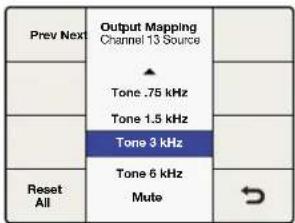
3 kHz tone mapped to Output 13
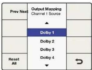
Dolby 1 mapped to Output 1

Output 16 is muted
Above are examples of output mapping choices.
Input Mapping Menu
Teranex 2D models have multiple audio input types including embedded SDI and HDMI audio, plus separate analog and AES/EBU audio inputs. With only a few exceptions, which are contained in the points listed below, you can map the audio from any of these inputs into your Teranex 2D independent of the video source selected.
TIP Use the 'input mapping' functionality in Teranex 2D to select the audio inputs you would like for your audio source. You can even map different audio input types to various audio output channels for extremely flexible audio control.
- 'Input mapping' is available via the front panel LCD menus and the 'audio' tab in the Teranex setup application.
- When audio input sources are selected, the corresponding front panel buttons 'embed', 'AES' and/or 'anlg' will illuminate to indicate that audio has been selected from those sources.
- Analog audio via RCA and DB25 inputs are available simultaneously via the 'input mapping' menu.
- Pressing any 'audio' input source button on the front panel will reset the 'input mapping' menu to the default mapping configuration for that input. The current input mapping will be lost.
- Pressing 'factory reset' will set the input selection to 'embed'.
- 'Presets' may be used to save input mapping configurations for later recall. Also, if power is lost, the 'power on' preset will save the mapping for use when power is restored.
- Only one embedded audio source is available at any given time. The embedded audio source in use is determined by your selection of SDI or HDMI video inputs.
- If your video source is 'anlg', you may only use the audio from the 'AES' and/or 'anlg' input connectors. Embedded audio channels from the SDI or HDMI inputs may not be used.
- If Dolby encoded audio is present on your 'AES' input, you cannot mix 'AES' with other audio input types. In this situation, you should select 'AES' as your input type.

Embedded 1/2 mapped to Input 1/2 Source
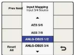
ANLG-DB25 1/2 mapped to Input 3/4 Source
Audio Gain Menu
The 'audio gain' control allows you to vary the output from -32 to +16 dB in 0.1 dB increments. Turn the knob to adjust. Pressing the knob will return the 'gain' to zero.
![graph TD A["Video Main Menu"] --> B["Audio"] A --> C["Noise Reduction"] A --> D["Ancillary Data"] A --> E["System Setup"] B --> F["Output Options"] C --> G["→"]](/content/2026/05/812948/images/74e0a8222a63f8832279160e83da62791787e5a23fff87467779d65a1282bdd6.jpg)
Main Menu>Audio Audio Menu>Audio Gain
![graph TD A["Audio Mapping"] --> B["Audio"] C["Audio Gain"] --> B D["Audio Delay"] --> B E["Setup"] --> B B --> F["0.0"] G["Audio Meters"] --> H[" "] I["→"] --> J[" "]](/content/2026/05/812948/images/8b0453ef76c2592c30f174358221e5b8bb35257915fa82451400c42a507355e1.jpg)
Turn knob to adjust gain
Audio Delay Menu
The maximum audio delay is 1 second. In the menu, you may chose between a 'time delay' or 'frame delay' adjustment. Time is resolved to millisecond resolution, while frame delay is expressed in one-half frame increments. In addition, audio may be advanced by up to 1 frame. Turn the knob to adjust. Pressing the knob will return the 'delay' to zero.
| Output Mapping | Audio | Input Mapping |
| Audio Gain | ||
| Audio Delay | ||
| Setup | ↘ |
Audio Menu>Audio Delay

Turn knob to adjust Time Delay
![graph TD A["Frame Delay"] --> B["0.0"] C["Time Delay"] --> B B --> D["Output"]](/content/2026/05/812948/images/76fc2b54df0ce2d184be1c8e75482c9c47a39f80428c0cda0c328e5ca4ee9827.jpg)
Turn knob to adjust Frame Delay
Audio Setup Menu
In Teranex processors with analog audio inputs, the 'audio setup' menu includes an analog audio input reference level adjustment and analog input type selection.
Analog In Level for Teranex 2D and Teranex 3D
Teranex 2D and 3D processors are factory set to analog audio input reference levels of + = -20dBFS. If you are using a different analog input reference level, you may adjust the 'level' control to compensate.
NOTE This setting will not affect the RCA audio input level.
Turn the knob to adjust. The range of adjustment is -12 to +12dB. Pressing the knob will return the level to zero.
![graph TD A["Video Main Menu"] --> B["Audio"] A --> C["Noise Reduction"] A --> D["Ancillary Data"] A --> E["System Setup"] A --> F["Output Options"] A --> G["→"]](/content/2026/05/812948/images/f0777bd52800628b32874ff55e3a2a735f39f60f140be75c1042b7af68cf2926.jpg)
Main Menu>Audio Menu
![graph TD A["Output Mapping"] --> B["Audio"] C["Audio Gain"] --> B D["Audio Delay"] --> B E["Setup"] --> B B --> F["Input Mapping"] B --> G["→"]](/content/2026/05/812948/images/d384926f7fac9b42f21b8c9af688d8554a176fc2159ae6ed6c4a9ba559bbb622.jpg)
![graph TD A["Analog In Level"] --> B["Setup"] B --> C["Analog Input"] B --> D["0.0"] D --> E[" "] D --> F[" "] D --> G[" "] D --> H["?"]](/content/2026/05/812948/images/7d19bac1590b36c16b8faa31dd05dda92e9e4fd7d28b85640d2e4a4dfe5eb3f7.jpg)
Setup Menu>Analog In LevelAudio Menu>Setup Menu
Analog In Level for Teranex AV only
Teranex AV provides an input level selection menu that offers a choice between two audio standards, such as SMPTE -20dBFS and EBU -18dBFS.
![graph TD A["Video Main Menu"] --> B["Audio"] A --> C["Noise Reduction"] A --> D["Ancillary Data"] A --> E["System Setup"] B --> F["Output Options"] C --> G["→"]](/content/2026/05/812948/images/3a5b594e2d95541d2ed434429d1d0866593c9e94a9b8261c3d5778aaa1f24c34.jpg)
Main Menu>Audio Menu
![graph TD A["Output Mapping"] --> B["Audio"] B --> C["Audio Meters"] D["Audio Gain"] --> B E["Audio Delay"] --> B F["Setup"] --> B B --> G["→"]](/content/2026/05/812948/images/b5174ffa53e8761661f7f5e9367bdf8e5bf83a7e6efedf6b8a4d412c2efa02d4.jpg)
Audio Menu>Setup Menu

Setup Menu>Analog In Level
Analog Input Menu
The 'audio setup' menu lets you select between the various analog audio input types.
The choices for Teranex 3D and Teranex AV are RCA Phono or XLR. The choices for Teranex 2D are RCA Phono or DB25.
- RCA
Stereo RCA Phono connectors. Default for the Teranex 2D and 3D processors.
- DB25 for Teranex 2D only
Balanced analog audio input via the DB25 connector.
- XLR for Teranex 3D and Teranex AV only
Balanced analog audio input via the XLR connectors.
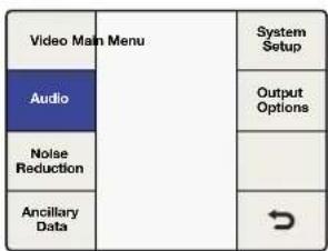
Main Menu>Audio
![graph TD A["Output Mapping"] --> B["Audio"] C["Audio Gain"] --> B D["Audio Delay"] --> B E["Setup"] --> B B --> F["Input Mapping"] B --> G["→"]](/content/2026/05/812948/images/85759bc6551daf56415b5a5ab9035eacda63389923d97a68d53ae2d18ee0ec8b.jpg)
Audio Menu>Setup
| Analog In Level | Audio Setup | Analog Input |
| RCA | ||
| DB25 | ||
Setup Menu>Analog Input for Teranex 2D
| Analog In Level | Audio Setup | Analog Input |
| RCA | ||
| XLR | ||
| ↘ |
Setup Menu>Analog Input for Teranex 3D and Teranex AV
Audio Meters for Teranex AV only
The Teranex AV allows you to select which pair of input or output audio channels will be displayed on the front panel LCD. The channel numbers are displayed below the meters for confirmation.

Main Menu>Audio Menu
| Output Mapping | Audio | Audio Motors |
| Audio Gain | Channels 1&2 | |
| Channels 3&4 | ||
| Audio Delay | Channels 5&6 | |
| Channels 7&8 | ||
| Setup | Channels 9&10 | → |
Audio Menu>Audio Meters

Channel numbers are shown below the audio meters
When a Dolby Digital or Dolby E encoder is installed in the Teranex 3D, two additional selections will appear in the Audio Menu:
Dolby Encode Menu
The 'dolby encode' menu will allow you to select your source for each channel to be encoded. For Dolby Digital encoding, you may select up to 6 channels to be encoded. For Dolby E, you may select up to 8 channels.
You may select from discrete audio channels, Dolby decoded channels if a Dolby decoder is installed, test tones or mute. This menu is similar to the 'output mapping' menu, but you should understand that the sources selected in the 'dolby encode' menu will be mapped to two Dolby encoded channels, which may later be mapped to your output.
As an example, let's say that you need to encode input channels 3 through 10 to Dolby E and you want your Teranex to provide Dolby E encoded audio outputs on SDI channels 9 and 10.
- First, you would use the 'dolby encode menu to route 'input 3' as the source for Dolby Encode channel 1.
- Press the 'next' button on the menu to move to Dolby Encode channel 2 and route 'input 4' to it. Continue this process until you have routed the remaining input channels 5-10 to Encoder channels 3-8.
- The 8 input sources routed to the Dolby E encoder module will result in two encoded output channels. Using the 'output mapping' menu in the 'audio menu settings' section of this manual, you would map the two Dolby E encoded channels, which we call 'encode 1' and 'encode 2', to your SDI output channels 9 and 10.

Main Menu>Audio Menu
| Output Mapping | Audio | Dolby Encode |
| Audio Gain | Dolby Metadata | |
| Audio Delay | ||
| Setup |
Audio Menu>Dolby Encode

Select sources for Dolby encoder channels
Dolby Metadata Menu
'Dolby metadata' describes the encoded audio and conveys information to control downstream equipment. Metadata is usually carried in the Dolby Digital or Dolby E bitstream, but can also be carried as a serial data stream between Dolby E and/or Dolby digital equipment.
In Teranex 3D, Dolby metadata may be derived from incoming Dolby audio, if a Dolby decoder is installed, and may also be input as serial data via the 9-pin Dolby metadata connector on the rear of the Teranex 3D. You may also generate your own metadata in the Teranex 3D by using one of the two commonly used configurations provided in the 'dolby metadata' menu, 'stereo' and '5.1'. See the configurations assigned by each in the table below. The variations between the two configurations are shown by bold text.
| Video | Main Menu | System Setup |
| Audio | Output Options | |
| Noise Reduction | ||
| Ancillary Data | ↘ |
Main Menu>Audio
![graph TD A["Audio"] --> B["Output Mapping"] B --> C["Audio Gain"] C --> D["Audio Delay"] D --> E["Setup"] F["Dolby Encode"] --> G["Dolby Metadata"] G --> H["→"]](/content/2026/05/812948/images/7e105c2ebecbb6d78f15febd62d4b993aea29754b41cd3a05a6f68f31972824e.jpg)
Audio Menu>Dolby Metadata

Dolby Metadata Menu
The 'dolby metadata' menu provides for:
Pass-Thru
If your Teranex 3D also contains a 'dolby decoder' module, any metadata derived from the decoded Dolby stream will be reinserted in the Dolby encoded output.
- External
To add metadata from an external metadata generator to your Dolby encoded output, connect the generator to the '9 pin dolby metadata' connector on the rear panel.
- Stereo
Pre-configured metadata for stereo output.
5.1
Pre-configured metadata for 5.1 encoding, typically used with Dolby digital encoding.
| Metadata Parameter Stereo 5.1 | ||
| Program Configuration 4x2 5.1+2 | ||
| Program Description Text Not programmed Not programmed | ||
| Frame Rate Set by Conversion Set by Conversion | ||
| Bitstream Mode Complete Main Complete Main | ||
| Channel Mode | 2/0 L/R | 3/2 L,C,R,Ls,Rs |
| Center Downmix Level -3 dB | -3 dB | |
| Surround Downmix Level | -3 dB | -3 dB |
| Dolby Surround Mode | Not Indicated | Not Indicated |
| LFE Channel | LFE Off | LFE On |
| Dialogue Normalization | 27 | 27 |
| Audio Production Information | No | No |
| Mix Level | 0 | 0 |
| Room Type | Not Indicated | Not Indicated |
| Copyright Bit | Yes | Yes |
| Original Bitstream Yes Yes | ||
| Extended Bitstream Info 1 Yes Yes | ||
| Preferred Stereo Downmix Not Indicated Not Indicated | ||
| Lt/Rt Center Downmix Level -3 dB -3 dB | ||
| Lt/Rt Surround Downmix Level -3 dB -3 dB | ||
| Lo/Ro Center Downmix Level -3 dB -3 dB | ||
| Lo/Ro Surround Downmix Level -4.5 dB -4.5 dB | ||
| Extended Bitstream Info 2 Yes Yes | ||
| Dolby Surround EX Mode | Not Indicated Not Indicated | |
| Dolby Headphone | Not Indicated Not Indicated | |
| A/D Converter Type | Standard | Standard |
| DC Filter | Enabled | Enabled |
| Lowpass Filter | Enabled | Enabled |
| LFE Lowpass Filter | Disabled | Enabled |
| Surround Phase Shift | Disabled | Enabled |
| Surround 3 dB Attenuation | Disabled | Enabled |
| RF Mode Compression Info | None | None |
| RF Mode Compression Profile | Film Standard | Film Standard |
| Line Mode Compression Info | None | None |
| Line Mode Compression Profile Film Standard | Film Standard | |
Noise Reduction Menu Settings
The ‘noise reduction’ algorithm in Teranex processors looks at each pixel in an image and processes it based on motion and types of noise. Spatial noise reduction is applied to still areas of the picture and temporal recursive noise reduction is applied to moving areas. Using both types provides higher quality results.
To enable noise reduction, go to Main Menu>Noise Reduction and select 'on' using the soft menu buttons and rotary knob.
NOTE 'Noise reduction' is not available while performing frame rate conversions, such as 486i59.94 to 576i50 NTSC to PAL or 1080i59.94 to 1080i50.

Main Menu>Noise Reduction
![graph TD A["Enable"] --> B["Noise Reduction"] B --> C["Split Screen"] D["Bias"] --> E["On"] D --> F["Off"] E --> G["Red Overlay"] F --> H["¬"] I[" "] --> J["↔"]](/content/2026/05/812948/images/e7e1605732f8587559ffa3fb0afa0cabb7f5b2fe2d96bfb5221536b21287b36b.jpg)
Noise Reduction Menu
Bias Menu
Adjust the 'bias' level to set the amount of noise reduction. The higher the 'bias' value, the more aggressive the noise reduction.
- The Bias range is -6 to +6.
- The default value is 0.
![graph TD A["Enable"] --> B["Set Value"] C["Bias"] --> B B --> D["Split Screen"] B --> E["Red Overlay"] B --> F["→"]](/content/2026/05/812948/images/f8b0fa185d1c5a922d06dbeed7e7ade7cfba0d28124eef1d1d7bb7f0bdd00381.jpg)
Noise Reduction Menu>Bias
Split Screen Menu
Split Screen divides the LCD, one half with noise reduction and one half without. This lets you compare your noise reduction settings to the original image.
To enable 'split screen', go to Main Menu>Noise Reduction>Split Screen and select 'on' using the soft menu buttons and rotary knob.
![graph TD A["Enable"] --> B["Split Screen"] C["Blas"] --> D["On"] C --> E["Off"] F[" "] --> G[" "] H[" "] --> I[" "] J[" "] --> K[" "] L[" "] --> M[" "] N[" "] --> O[" "] P[" "] --> Q[" "] R[" "] --> S[" "] T[" "] --> U[" "] V[" "] --> W[" "] X[" "] --> Y[" "] Z[" "] --> AA[" "] AB[" "] --> AC[" "] A…](/content/2026/05/812948/images/f3688696cb89cf21100f21eb6563d94fa37d1c1b974f6f084d9a607160beeb62.jpg)
Noise Reduction Menu>Split Screen
Red Overlay Menu
In 'red overlay' mode, pixels in motion will be colored red. Temporal recursive noise reduction will not be applied to these pixels. Turning the 'red overlay' on will also allow you to see the effect of noise reduction 'bias' adjustments.
To enable 'red overlay', go to Main Menu>Noise Reduction>Red Overlay and select 'on' using the soft menu buttons and the rotary knob.
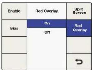
Noise Reduction Menu>Red Overlay

The red overlay helps to show which parts of the image have temporal recursive noise reduction applied.
Ancillary Data Menu Settings
The ‘ancillary data’ menu provides access to closed caption, timecode and video index features.
Closed Caption Menu
The ‘closed caption’ menu lets you configure closed captions for CEA-608B and CEA-708B standards. CEA-608B is the closed captioning reference standard for SD NTSC analog and SD-SDI. Captions are encoded on line 21 of the vertical blanking interval. CEA-708B is the standard for HD-SDI, typically encoding captions on line 9.
The Teranex processor automatically detects digital captions in both SD and HD video formats. If digital captions are not present in an SD signal, the processor will look for analog captions on line 21. If the program has captions on line 21 but you're not seeing them, set the 'analog in line' menu to look for captions on lines 20 or 22.
TIP Closed caption processing also supports up conversion of 608 CC2 and CC3 secondary language services to 708 Service 2, or S2, via the 'service 2 source' menu.
| Video Main Menu | System Setup | |
| Audio | ||
| Noise Reduction | ||
| Ancillary Data | ||
Main Menu>Ancillary Data
| Closed Caption | Ancillary Data | Video Index |
| Timecode | ||
| ↘ |
Ancillary Data Menu
| Closed Caption | Ancillary Data | Video Index |
| Timecode | ||
| ↘ |
Ancillary Data Menu>Closed Caption
| CC Enable | Closed Caption | Service 2 Source |
| Analog In Line | On | Service 1 Language |
| Off | ||
| Analog Out Line | Service 2 Language | |
| Reset All |
Closed Caption Menu>CC Enable
The ‘closed captioning’ menu offers the following selections and adjustments:
- CC Enable
Turns 'closed captions' 'on' or 'off' in the output video.
- Analog In Line
Allows you to select the analog 'closed caption' input line.
- Analog Out Line
Allows you to select the analog 'closed caption' output line.
- Service 2 Source
Allows you to select between CC2 and CC3 as the 'closed caption' 'service 2' source.
- Service 1 Language
Allows you to select the language used for 'service 1'.
- Service 2 Language
Allows you to select the language used for 'service 2'.
CC Enable
'CC enable' is 'off' by default. To enable closed captioning, go to Main Menu>Ancillary Data>Closed Caption>CC Enable and select 'on' using the soft menu buttons or rotary knob.
Disabling captions may be helpful if the incoming closed caption data is incorrect or corrupt.
The CC status LED on the front panel is tied to the 'in' or 'out' selection. When 'in' is selected, the CC status LED will illuminate when closed captioning is detected in the input video.
When ‘out’ is selected, the CC status LED will illuminate when closed captioning data is present in the output video.
Analog In Line
'Analog in line' identifies the line on which closed caption information is located in the incoming video. This menu applies only to sources with analog closed captions. If your captions are digital, they will be automatically detected.
- The range of adjustment is lines 20 to 22.
- The default setting is line 21.
| Closed Caption | Ancillary Data | Video Index |
| Timecode | ||
| ↘ |
Ancillary Data Menu>Closed Caption

Closed Caption Menu> Analog In Line
Analog Out Line
'Analog out line' identifies the line on which closed caption information is located in the output video. This menu applies only to analog SD output.
- The range of adjustment is lines 20 to 22.
- The default setting is line 21.
Service 2 Source
‘Service 2 source’ allows you to select CEA-608 CC2 or CC3 for up converting to CEA-708, ‘service 2’.
- The choices are CC2 and CC3.
- The default setting is CC2.
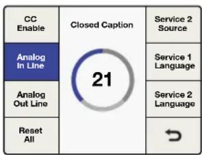
Closed Caption Menu> Analog Out Line
| CC Enable | Set Value | Service 2 Source |
| Analog In Line | CC 2 | Service 1 Language |
| CC 3 | ||
| Analog Out Line | Service 2 Language | |
| Reset All |
Closed Caption Menu> Service 2 Source
Service 1 Language
'Service 1 language' is used to select the language for that service in CEA-708 closed captions.
- The language choices are:
English
French
German
Italian
Spanish
- The default language is English.
| CC Enable | Set Value | Service 2 Source |
| Analog In Line | English | Service 1 Language |
| French | ||
| Analog Out Line | German | Service 2 Language |
| Italian | ||
| Reset All | Spanish |
Closed Caption Menu>
Service 1 Language
Service 2 Language
'Service 2 language' is used to select the language for that service in CEA-708 closed captions.
- The language choices are:
English
French
German
Italian
Spanish
- The default language is English.
| Closed Caption | Ancillary Data | Video Index |
| Timecode | ||
Ancillary Data
Menu>Closed Caption
| CC Enable | Set Value | Service 2 Source |
| Analog In Line | English | Service 1 Language |
| French | ||
| Analog Out Line | German | Service 2 Language |
| Italian | ||
| Reset All | Spanish |
Closed Caption Menu>
Service 2 Language
Timecode Menu
Teranex lets you send incoming timecode to the output, strip incoming timecode completely or generate new timecode. Similar to broadcast decks, you can select the desired timecode mode, such as 'input regen' and 'jam sync', or set specific timecode data.
To enable timecode processing, go to Main Menu>Ancillary Data>Timecode and choose your desired timecode mode.
Timecode Generator
The 'timecode generator' menu lets you choose from four available timecode modes, or disable manual timecode processing.
Off
No timecode data will be inserted into the output video. This is the default setting.
![graph TD A["Timecode"] --> B["Ancillary Data"] B --> C["Video Index"]](/content/2026/05/812948/images/30e22316506a5e6644a6edd34fcbc66eb78c960cdfac5ac514fb43222c3f713c.jpg)
Ancillary Data Menu>Timecode
![graph TD A["Setup"] --> B["Set Timecode"] B --> C["Timecode Generator"] C --> D["Off"] D --> E["Input Regen"] E --> F["Jam Sync"] F --> G["NextPrev"] D --> H["Start Source"]](/content/2026/05/812948/images/b9dee3c0507d3b0648bcc2cbd57ffcdb97c25b406e72ca3ec748a9d49f0d902b.jpg)
Timecode Menu
Input
Select 'input' mode to feed the input timecode directly to the output. This is useful if you want to preserve your source timecode and your input and output frame rates are the same.
It's important to make sure that the 'drop frame' mode in the 'timecode setup' menu is set to 'auto' to ensure the output timecode will match the input timecode.
NOTE If you want to ensure the output timecode matches your input timecode, do not use an external reference. The external reference can cause a dropped or duplicated frame in the output, which will affect your timecode count.
To set the 'reference' menu to 'input', go to Main Menu>Setup>Reference and select 'input'.
![graph TD A["Timecode Generator"] --> B["Off"] A --> C["Input"] D["Set Timecode"] --> E["Input Regen"] D --> F["Generate"] D --> G["Jam Sync"] H["Setup"] --> I["→"]](/content/2026/05/812948/images/b1b450681d1bc2189c7f62e6bee8a65ddd26e422d14bb657c0b01bc9fe418227.jpg)
Timecode Generator Menu>Input
Input Regen
The 'input regen' mode synchronizes the input timecode to the output timecode and is often used when performing frame rate conversions, such as 1080i50 to 1080i59.94.
'Input regen' mode should only be used when your Teranex processor is locked to your input video.
'Drop frame' and 'non drop frame' modes are both supported in 23.98, 29.97 and 59.94 frame rates. However, in a conversion where the source timecode is drop frame and the output format supports only non drop frame timecode, the output timecode will be automatically converted to non drop frame.
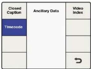
Ancillary Data Menu> Timecode
![graph TD A["Timecode Generator"] --> B["Off Input"] B --> C["NextPrey"] D["Set Timecode"] --> E["Input Regen"] E --> F["Generate Jam Sync"] G["Setup"] --> H["→"]](/content/2026/05/812948/images/b417f1ecd05072b5e0aed0faca9811ead22acf51150df842c62c2c7854dde872.jpg)
Timecode Menu>Input Regen
Generate
The timecode generator will generate free running output timecode appropriate for the selected output format, even if timecode is not present on your video input signal.
- Set Timecode
The 'set timecode' menu options you will have are determined by the selection you make in the 'start source' menu.
- Start Source = "Input"
If the 'start source' menu is set to 'input', the 'set timecode' menu will show 'input' as the start value' for the generator. When you press the 'start' button, the generator will capture the current input timecode value and use that value to start outputting free running timecode. If no timecode is present on your input video source, the generator will begin counting at 00:00:00:00.
- Start Source = "Start Value"
If the 'start source' menu is set to 'start value', the 'set timecode' menu will display an eight-character register that allows the entry of a specific starting value for the generator. Turn the rotary knob to adjust the timecode generator values and use the 'previous' and 'next' buttons to move the cursor left or right. When you press the 'start' button the timecode generator will immediately output timecode from your 'start value' entry.
![graph TD A["Setup"] --> B["Jam Sync"] B --> C["Generate"] C --> D["Set Timecode"] D --> E["Input Regen"] E --> F["Off Input"] F --> G["Timecode Generator"] G --> H["NextPrev"]](/content/2026/05/812948/images/d5fa0998d631e9087b7c36f1e440a2e20f59d2f2ce5d8f66d08cc74b533aa63a.jpg)
Timecode Menu>Generate
![graph TD A["Setup"] --> B["Set Timecode"] B --> C["Timecode Generator"] C --> D["Timecode"] D --> E["NextPrev"] E --> F["Start"] F --> G["Start Source"] G --> H["→"] style A fill:#f9f,stroke:#333 style B fill:#ccf,stroke:#333 style C fill:#cfc,stroke:#333 style D fill:#fcc,stroke:#333 style E fill:#…](/content/2026/05/812948/images/eb7e96fe9552648fe17fb13aad7ceb5d5a4633b2116e1afa5ee6e62259bb8e46.jpg)
Generate>Start Source
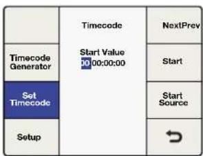
Set Timecode Menu. Use the Rotary knob to set your values, and the Previous and Next buttons to move the cursor left and right.
Jam Sync
The 'jam sync' mode is similar to the 'generate' mode. However, when you press the 'start' button, 'jam sync' mode allows you to hold the output timecode generator until a pre-determined timecode point is reached in your input video, called the 'jam sync' value. The 'jam sync' value must be entered via the 'set timecode' menu.
![graph TD A["Timecode Generator"] --> B["Off Input"] B --> C["Set Timecode"] C --> D["Input Regen Generate"] D --> E["Jam Sync"] E --> F["→"] style A fill:#4A90E2,stroke:#333 style B fill:#FFD700,stroke:#333 style C fill:#FFD700,stroke:#333 style D fill:#FFD700,stroke:#333 style E fill:#FFD700,stroke…](/content/2026/05/812948/images/d4d2714c49e9fbe1058918b8233a45db11b97ca73605b5c561363055e2a5dfa8.jpg)
Timecode Menu>Jam Sync
- Set Timecode
The 'set timecode' menu options you will have are determined by the selection you make in the 'start source' menu.
| Timecode | NextPrev | |
| Timecode Generator | Start Value Input | Start |
| Set Timecode | Jam Sync 00:00:00 | Start Source |
| Setup | → |
Jam Sync>Set Timecode
- Start Source = "Input"
If the 'start source' menu is set to 'input', the 'set timecode' menu will show 'input' as the 'start value' for the timecode generator. When you press the 'start' button, the generator will start looking for a timecode match to the 'jam sync' value you have entered. When the match occurs, the generator will use that 'input' timecode as the start value to generate free running output timecode.
- Start Source = "Start Value"
If the 'start source' menu is set to 'start value', the 'set timecode' menu will display an eight-character register that allows the entry of a specific starting value for the generator. When you press the 'start' button the generator will look for a timecode match to the 'jam sync' value you have entered. When the match occurs, the generator will use the start value you entered to generate free running output timecode.
Video Index Menu
The 'video index' menu enables or disables reaction to video indexing signals that may be embedded in your source video. The three video indexing modes that are supported are Active Format Description, or AFD, Wide Screen Signaling, or WSS, and SMPTE RP186.
Index Reaction
If 'index reaction' is turned 'on', the Teranex processor will be set to react to incoming video indexing signals. The processor will automatically scan for the presence of video index packets and will react to them if found. AFD indexing takes precedence over the WSS, which takes precedence over RP186.
- The default setting is 'off'.
NOTE The Teranex processor will not pass or insert WSS or RP186 codes. It will only react to them if they are present on the input.
| Closed Caption | Ancillary Data | Video Index |
| Timecode | ||
![graph TD A["Index Reaction"] --> B["Index Reaction"] B --> C["On"] B --> D["Off"] C --> E["AFD Insertion"] D --> F["AFD Inser Line"] G[" "] --> H[" "] I[" "] --> J[" "]](/content/2026/05/812948/images/d8d5ef509b53d0c041c5c2c2ff20293ac498242134c9b07feb2a95168a549760.jpg)
Ancillary Data Menu>Video Index Video Index Menu>Index Reaction
AFD Insertion Menu
This menu allows you to select the desired AFD code that will be inserted in the output video. The output line on which the code will be inserted can be selected in the AFD Insert Line menu.
- Settings include:
Off
No AFD code will be inserted in the output ancillary data space.
Auto
The appropriate code will be inserted based on the current video output format.
Bypass
Any code present in the incoming video stream will be passed through to the output.
AFD codes 0000 - 1111
These codes are manual selections which may be used as needed.
- The default setting is 'off'.

Video Index Menu>AFD Insertion
AFD Insert Line Menu
If AFD Insertion is enabled in the 'AFD insertion' menu above, the 'AFD insert line' menu allows you to select the line on which the AFD code will be inserted in the ancillary data space of the output video signal.
The range of adjustment is dependent on the current output video format:
- For SD formats, the range is lines 10 to 19. The default value is line 15.
- For HD 1080 formats, the range is lines 9 to 20. The default value is line 11.
- For HD 720 formats, the range is lines 9 to 25. The default value is line 11.
Press the rotary knob to go back to the default value.

Video Index Menu>AFD Insert Line
System Setup Menu Settings
The ‘system setup’ menu provides access to the ‘ethernet,’ ‘factory reset’ and ‘reference’ menus, as well as a system ‘info’ screen. Teranex AV offers additional selections, including processing latency and still frame capture controls.
Ethernet Menu
The 'Ethernet' menu allows you to display the current settings and assign new settings for static 'IP' address, 'subnet mask' address and IP 'gateway'. This menu also permits you to turn DHCP 'on' or 'off'.
When DHCP is 'on', the IP, 'subnet mask' and 'gateway' menus will display the addresses currently assigned to the chassis by the DHCP server. These values may not be adjusted unless DHCP is 'off'.
IP Menu
To set a static IP address for the Teranex processor, DHCP must be 'off'.
The IP menu will display a four-field register allowing you to enter specific IP address values. Adjust the selection highlighted by the cursor by turning the rotary knob. Use the 'prev' and 'next' buttons to move the cursor to the left or right, respectively. If you change this setting, press the 'back' button, then press the 'save and restart' button to power cycle the chassis and establish the new setting.
| Video Main Menu | System Setup | |
| Audio | ||
| Noise Reduction | ||
| Ancillary Data | ||
Main Menu>System Setup
![graph TD A["Ethernet System Setup"] --> B["Factory Reset"] A --> C["Reference"] A --> D["Info"] A --> E["→"]](/content/2026/05/812948/images/9ea92703c8fb3dde7f3f7ea329eca8b0f5708e6b9935f65f91c142c509130cec.jpg)
System Setup Menu>Ethernet
![graph TD A["Prev"] --> B["Ethernet"] C["IP"] --> B D["Subnet Mask"] --> B E["Save and Restart"] --> B B --> F["Next"] B --> G["Getaway"] B --> H["DHCP"] B --> I["→"]](/content/2026/05/812948/images/35dda0449044e6ec82a1cfcd223bbc5a3abbc40dda685993c15c2815cd3f2ca0.jpg)
System Setup Menu>Ethernet>IP
Subnet Mask Menu
The ‘subnet mask’ menu will display a four-field register allowing you to enter specific values. Adjust the selection highlighted by the cursor by turning the rotary knob. Use the ‘prev’ and ‘next’ buttons to move the cursor left or right, respectively. If you change this setting, press the ‘back’ button, then press the ‘save and restart’ button to power cycle the chassis and establish the new setting.

System Setup Menu> Ethernet>Subset Mask
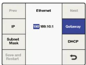
System Setup Menu>Ethernet>Gateway
![graph TD A["Prev"] --> B["Ethernet"] C["IP"] --> D["On"] C --> E["Off"] F["Subnet Mask"] --> G["DHCP"] H["Save and Restart"] --> I["→"]](/content/2026/05/812948/images/1b19adb8235534b31c56e16648ba345d18db4cc4da41a6573bcb6559a725726b.jpg)
System Setup Menu> Ethernet>DHCP
Gateway Menu
The ‘gateway’ menu will display a four-field register allowing you to enter specific values. Adjust the selection highlighted by the cursor by turning the rotary knob. Use the ‘prev’ and ‘next’ buttons to move the cursor left or right. To establish new settings, press the ‘back’ button, then ‘save and restart’. Your Teranex will power cycle and apply the new settings.
DHCP Menu
The DHCP menu enables or disables the assignment of an IP address to the chassis using 'dynamic host configuration protocol' or DHCP. You can press the DHCP soft button or turn the rotary knob to turn DHCP 'on' or 'off'. If you change this setting, press the 'save and restart' button to power cycle the chassis and establish the new IP address.
- ON
The Teranex processor will accept an IP address assigned by your network router.
- OFF
The previous static IP address of the unit will be used if one was previously assigned.
If you press the IP button with 'DHCP' 'on' and see an IP address of 0.0.0.0, this indicates that the processor was unsuccessful in obtaining an IP address from the DHCP server. Please check your Ethernet network connections.
Processing Menu for Teranex AV only
The ‘processing’ menu allows you to change the latency, or processing delay, through the Teranex AV. This feature is ideal when using a Teranex AV in live broadcast or production situations and can reduce the latency down to 2 frames.
The processing modes are:
- Lowest latency
In this mode format conversions will run with minimal latency, typically 2 frames.
- Highest quality
In this mode, all conversions will run with the same high quality algorithms currently used in Teranex processors.
| Video Main Menu | System Setup |
| Audio | Output Option |
| Noise Reduction | |
| Ancillary Data | ↘ |
Main Menu>System Setup
| Ethernet System Setup | Factory Reset | |
| Processing | Lowest Latency | Reference |
| Highest Quality | ||
| Still Frame | Info | |
| → | ||
System Setup>Processing
Still Frame Menu for Teranex AV only
The still frame menu allows you to capture a full-frame image from the active video input or the freeze frame buffer of the Teranex AV. This means that you can capture a still from an HDMI input, like a computer, or from an SDI source, such as a camera. The still frame is saved into non-volatile memory, which means it will be preserved after a power cycle or until you decide to delete it or overwrite it with a new still.
Capture Mode
Pressing 'capture mode' will open a confirmation screen. Press 'capture' on the new screen to grab from the current input signal or, if a freeze is present, from the freeze frame buffer. Press 'cancel' to abort the process. Your still frame will be captured at the current output resolution of the Teranex AV. You may store other still frames at other resolutions by changing the output format of the Teranex AV to the new resolution and repeating the capture process.
If a still frame exists in the Teranex AV at a specific resolution, capturing a new still frame at the same resolution will overwrite the existing still frame.
NOTE Saving a Still to non-volatile memory is a background task that can take up to 30 seconds for Ultra HD still images. If you plan to power down after saving a still, be sure to allow enough time for this process to be completed.
- Preview
Once a still frame has been captured, the 'preview' button will allow you to see the image for 3 seconds on the output of the Teranex AV. The Preview button will be grayed out, indicating that it is unavailable, if no still frame exists for the current output resolution.
- Delete
Press the 'delete' button to erase a still frame from memory. A confirmation screen will appear to prompt you to verify the deletion. You may also delete all still frames by performing a factory reset of the Teranex AV via the 'System Setup>Factory Reset' menu.
| Ethernet System Setup | Factory Reset | |
| Processing | Reference | |
| Still Frame | Info | |
| → | ||
System Setup>Still Frame
| Delete Stil | Frame | Capture Mode |
| Preview | ||
| ↘ |
Still Frame Menu

When deleting or capturing a still frame, a warning screen gives you the option to continue or cancel.

Still Frame File Transfer via Blackmagic Teranex Setup
Using the Blackmagic Teranex Setup utility, you can save still frame images from the Teranex AV to your computer and load images from your computer, such as a company logo, into your Teranex AV. The following file formats are acceptable: png (default), bmp, ppm, xbm, xpm, pbm, pgm.
Save to File
To save the current still frame from your Teranex AV to your computer, launch the Teranex Setup utility on your computer and connect to your Teranex AV. On the Setup tab, click on the 'save to file' button. A window will open on your computer permitting you to name the file and select a location in which to save it. Click 'save' and wait for the save to complete.
Load from File
To load a still image file from your computer to a Teranex AV, click on the 'load from file' button in the Setup tab of the Teranex Setup utility. A window will open on your computer permitting you to select the target file.
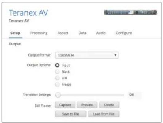
When loading a graphic from a computer, the file may be of any resolution. Image conversion software will automatically resize the image to the output resolution of the Teranex AV. It's important to note that this scaling is not done using Teranex algorithms and the quality will be lower than if the scaling was done internally. If scaling with the highest quality is important, send the image to the Teranex AV via SDI or HDMI and use the algorithms in the Teranex AV to scale it internally for the best results.
Factory Reset Menu
Select 'factory reset' to restore conversion setup settings to their factory defaults.
The following settings will not be affected:
- Presets.
- Output video settings, e.g., 'format, frame, rate'.
- Aspect selection; however, any adjustable aspect ratio settings will be reset to their default values.
- Ethernet IP address settings.
In the Teranex AV, all still images stored in the unit will be erased during a factory reset.
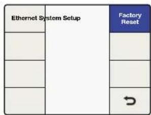
System Setup>Factory Reset

Press Reset to restore factory Settings, or Cancel to abort
Reference Menu Settings
The ‘reference’ menu allows you to synchronize your video output to an input video source or an external reference. In the Teranex AV, you may also choose its internal reference.
Type Menu
The 'type' menu is where you choose the source of your reference.
- Input
Selects the current input video source as the reference.
- External
Selects the external reference input.
- Internal
Synchronizes the output of the Teranex AV to its internal freerunning oscillator, which produces constant sync in the output stream, even when changing inputs to the unit.
| Video | Main Menu | System Setup |
| Audio | ||
| Noise Reduction | ||
| Ancillary Data | ↘ |
Main Menu>System Setup
![graph TD A["Ethernet"] --> B["System Setup"] B --> C["Factory Reset"] B --> D["Reference"] B --> E["Info"] B --> F["→"]](/content/2026/05/812948/images/12bd4f45ebf029c4f0dedcf6a787573e37eb8a6c658d0b49f6262eb9747ce60b.jpg)
System Setup>Reference

Reference>Type Menu for Teranex 2D, 3D and Express
![graph TD A["Type"] --> B["Reference"] B --> C["Pixel Offset"] D["Generate"] --> E["Input"] E --> F["Internal"] F --> G["External"] G --> H["Line Offset"] I[" "] --> J[" "] K[" "] --> L["→"]](/content/2026/05/812948/images/03cf21f7e89ead809177046ba1b0eb3b13226f7f23f5caf85a4d5829c1449849.jpg)
Reference>Type Menu for Teranex AV
External Reference Compatibility Chart
Your external reference must be compatible with the current output video format. The table below lists the external reference signals acceptable for each output video format and frame rate. This chart is also applicable for reference signals generated by the Teranex AV in the Generate menu.
If external reference is selected and a valid reference signal is detected, the 'REF' status LED on the front panel will illuminate. If the external reference is removed or lost, the 'REF' LED will be turned off and the processor will go into a free run condition until the reference is restored.
| Output Format and Frame Rate | Reference Signal |
| 525i59.94 NTSC Blackburst 59.94 | |
| 625i50 PAL Blackburst 50 | |
| 720p50 Blackburst 50 | |
| 720p59.94 Blackburst 59.94, Tri-level Progressive 59.94 | |
| 720p60 Tri-level Progressive 60 | |
| 1080p23.98 Tri-level Progressive 23.98, Tri-level Interlaced 47.96 | |
| 1080PsF23.98 Tri-level Progressive 23.98, Tri-level Interlaced 47.96 | |
| 1080p24 Tri-level Progressive 24, Tri-level Interlaced 48 | |
| 1080PsF24 Tri-level Progressive 24, Tri-level Interlaced 48 | |
| 1080p25 Blackburst 50, Tri-level Progressive 25, Tri-level Interlaced 50 | |
| 1080PsF25 | Blackburst 50, Tri-level Progressive 25, Tri-level Interlaced 50 |
| 1080p29.97 | Blackburst 59.94, Tri-level Progressive 29.97, Tri-level Interlaced 59.94 |
| 1080PsF29.97 Blackburst | 59.94, Tri-level Progressive 29.97, Tri-level Interlaced 59.94 |
| 1080p30 Tri-level Progressive | 30, Tri-level Interlaced 60 |
| 1080PsF30 Tri-level Progressive | 30, Tri-level Interlaced 60 |
| 1080i50 Blackburst | 50, Tri-level Interlaced 50 |
| 1080p50 Blackburst | 50 |
| 1080i59.94 Blackburst | 59.94, Tri-level Interlaced 59.94 |
| 1080p59.94 Blackburst | 59.94 |
| 1080i60 Tri-level Interlaced | 60 |
| 1080p60 Not supported | |
| 2K DCI 23.98p Tri-level Progressive | 23.98, Tri-level Interlaced 47.96 |
| 2K DCI 23.98PsF Tri-level Progressive | 23.98, Tri-level Interlaced 47.96 |
| 2K DCI 24p Tri-level Progressive | 24, Tri-level Interlaced 48 |
| 2K DCI 24PsF Tri-level Progressive | 24, Tri-level Interlaced 48 |
| 2160p23.98 Tri-level Progressive | 23.98, Tri-level Interlaced 47.96 |
| 2160p24 Tri-level Progressive | 24, Tri-level Interlaced 48 |
| 2160p25 | Blackburst 50, Tri-level Progressive 25, Tri-level Interlaced 50 |
| 2160p29.97 | Blackburst 59.94, Tri-level Progressive 29.97, Tri-level Interlaced 59.94 |
| 2160p30 Tri-level Progressive | 30, Tri-level Interlaced 60 |
| 2160p50 Blackburst | 50 |
| 2160p59.94 Blackburst | 59.94 |
| 2160p60 Not supported | |
Pixel Offset
If ‘external’ has been selected and a valid reference is present, this control will adjust the pixel timing of the output relative to the supplied external reference.
- The ‘range’ is determined by the current output format selection.
Line Offset
If 'external' has been selected and a valid reference is present, this control will adjust the line timing of the output relative to the supplied external reference.
- The 'range' is determined by the current output format selection.
![graph TD A["Ethernet"] --> B["System Setup"] C["Processing"] --> B D["Still Frame"] --> B E["Factory Reset"] --> F["Reference"] G["Info"] --> H["→"]](/content/2026/05/812948/images/932674c0e7fa144286c20061a01a5f4593eb121c31918f7f1287580ca8404ed1.jpg)
System Setup>Reference

Reference Menu>Pixel Offset
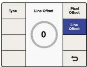
Reference Menu>Line Offset
Generate Menu for Teranex AV only
The Teranex AV can be used as a reference generator via its 'reference output' connection. The type of reference signal, black burst or Tri-level, is dependent on the output video format of the Teranex AV. Some video formats permit the use of specific reference types only. For example, if NTSC is your Teranex output format, only black burst at 59.94Hz will be generated. Similarly, for a 1080p23.98 output, only tri-level sync is possible. Other formats, such as 1080i59.94, allow the use of either type. The different Tri Level reference levels are Tri-level progressive, or TRI-P, and Tri-level interlaced, or TRI-I.
| Ethernet | System Setup | Factory Reset |
| Processing | Reference | |
| Still Frame | Info | |
| → |
System Setup>Reference
| Type | Reference | Pixel Offset |
| Generate | Blackburst | Line Offset |
| TriLevel | ||
| → |
Reference>Generate
| When your output video format is Your choices for generated reference signals are: | |
| 525i59.94 NTSC Blackburst 59.94 | |
| 625i50 PAL Blackburst 50 | |
| 720p50 Blackburst 50 or Tri-level Progressive 50 | |
| 720p59.94 Blackburst 59.94 or Tri-level Progressive 59.94 | |
| 720p60 Tri-level Progressive 60 | |
| 1080p23.98 Tri-level Progressive 23.98 | |
| 1080PsF23.98 Tri-level Interlaced 47.96 | |
| 1080p24 Tri-level Progressive 24 | |
| 1080PsF24 Tri-level Interlaced 48 | |
| 1080p25 Blackburst 50 or Tri-level Progressive 25 | |
| 1080PsF25 Blackburst 50 or Tri-level Interlaced 50 | |
| 1080p29.97 Blackburst 59.94 or Tri-level Progressive 29.97 | |
| 1080PsF29.97 | Blackburst 59.94 or Tri-level Interlaced 59.94 |
| 1080p30 | Tri-level Progressive 30 |
| 1080PsF30 Tri-level Interlaced 60 | |
| 1080i50 | Blackburst 50 or Tri-level Interlaced 50 |
| 1080p50 | Blackburst 50 |
| 1080i59.94 | Blackburst 59.94 or Tri-level Interlaced 59.94 |
| 1080p59.94 Blackburst 59.94 | |
| 1080i60 | Tri-level Interlaced 60 |
| 1080p60 Not supported | |
| 2K DCI 23.98p Tri-level Progressive 23.98 | |
| 2K DCI 23.98PsF Tri-level Interlaced 47.96 | |
| 2K DCI 24p Tri-level Progressive 24 | |
| 2K DCI 24PsF Tri-level Interlaced 48 | |
| 2160p23.98 Tri-level Progressive 23.98 | |
| 2160p24 Tri-level Progressive 24 | |
| 2160p25 Blackburst 50 or Tri-level Progressive 25 | |
| 2160p29.97 Blackburst 59.94 or Tri-level Progressive 29.97 | |
| 2160p30 Tri-level Progressive 30 | |
| 2160p50 Blackburst 50 | |
| 2160p59.94 | Blackburst 59.94 |
| 2160p60 Not supported | |
Info Menu
The ‘info menu’ displays the product model name and the version number of the software currently installed in your Teranex processor.
![graph TD A["Ethernet"] --> B["System Setup"] C["Processing"] --> B D["Still Frame"] --> B E[" "] --> F["→"] B --> G["Factory Reset"] B --> H["Reference"] B --> I["Info"]](/content/2026/05/812948/images/aee2e9927e580b522bfc609a356646f86a64749a1ae72d927c52e157a4f365ef.jpg)
System Setup>Info

Info Menu
Output Options Menu for Teranex AV only
The 'output options' menu provides four output selections, which permits you to quickly switch the output of the Teranex AV between the input video signal, internal black, a pre-stored still frame, or a captured 'freeze frame' from the input.
![graph TD A["Video"] --> B["Main Menu"] C["Audio"] --> B D["Noise Reduction"] --> B E["Ancillary Data"] --> B B --> F["System Setup"] B --> G["Output Options"] B --> H["→"]](/content/2026/05/812948/images/6b24756a9bd80eacac7b4fecd2738640dbfa9b4fb447b0f28a8a95d706f7606e.jpg)
Main Menu>Output Options
![graph LR A["Input"] --> B["Output Options"] B --> C["Transition Settings"] D["Black"] --> E F["Still"] --> G H["Freeze"] --> I I --> J](/content/2026/05/812948/images/7f89e4484ca4ac978e52570ef85bacd6965396271db713b8083de60897eeb989.jpg)
Output Options>Input

Output Options> Transition Settings
TIP If you need quick access to the 'output options'menu, you can assign this menu page to the 'menu 1' or 'menu 2' buttons on the Teranex AV front panel.
Input
'Input' refers to the video input that you currently have selected on the front panel. This may be SDI 1, SDI 2, HDMI or the fiber optic input, if installed. Video test patterns, selected via the 'Home > Video > Test Patterns' menu, are available through the 'input' selection.
Black
Press 'black' to switch the output to the internal black generator. No audio will be output while in this mode.
Still
Press 'still' to display a saved still frame. If no still frame is present in memory, the 'still' button will be grayed out and not selectable. No audio will be output while in this mode.
Freeze
Pressing 'freeze' will grab a screen capture of the current live video input. Selecting another button, such as 'input' or 'still,' will switch the output to the newly selected signal and will discard the freeze frame. No audio will be output while in this mode.
Transition Settings
The Transition Settings menu allows you to select a transition rate between 0 and 5 seconds, allowing you to cut or fade between video selections on the Output Options menu.
- A transition setting of 0 (zero) will perform a cut between selections.
- When switching between 'input' and 'still,' setting a transition rate greater than zero will produce a fade through black. For example, if the transition rate is set to 2 seconds, the fade from Source 1 to black will take 1 second and the fade from black to Source 2 will take one second, producing an overall transition time of 2 seconds. Audio present on Source 1 or Source 2 will fade out or in with the video at the same rate.
![graph LR A["Source 1"] --> B["Transition Rate"] B --> C["Source 2"] D["Fade through black"] --> C](/content/2026/05/812948/images/0b917249ff1e405569dab777b1ae4cbb320a2e3a8863ff580966cad8e90167ed.jpg)
- A transition to 'black' will use the entire time set by the transition rate. If the rate were set to 2 seconds, the fade to black would take the full 2 seconds. Audio present on Source 1 will fade down with the video at the same rate.

- The transition setting has no effect on a Freeze frame. When freeze is selected, the Teranex AV will immediately cut to the freeze frame regardless of the transition setting. Audio will be muted.
When you're ready to switch from Freeze to Input, Black or Still, the transition will obey the rules of the transition setting described above. In the example below, the audio on Source 2 will fade in with the video at the same rate.
![graph LR A["Source 1"] --> B["Freeze"] B --> C["Transition Rate"] C --> D["Source 2"] E["Cut to Freeze"] --> B F["Fade through black"] --> D](/content/2026/05/812948/images/72709b1655f05d74157a912b72b38bd55343d897a8f4909ca6e964c9a36cb6b1.jpg)
Press the front panel knob or turn it fully counterclockwise to reset the transition rate to zero. Output options, transition settings and still frame controls are also available via remote control in the Blackmagic Teranex Setup utility.

3D Menu Settings
The '3D' menu is available only in the Teranex 3D processor model. This menu enables the dual internal processors of the Teranex 3D Processor for format or frame rate conversion of stereoscopic inputs and for conversion of 2D sources into simulated 3D outputs.

Main Menu>3D
![graph TD A["3D Mode"] --> B["Off"] A --> C["Convert"] A --> D["2D to 3D"] A --> E["3D Align"] B --> F["Input"] C --> G["Output"] D --> H["Camera Align"] E --> I["Output"] B --> J["Intensity 3D"] C --> K["Depth"] D --> L["Depth"] E --> M["Depth"]](/content/2026/05/812948/images/b7e74c80958540b0a51d39bb12e863498a205a2d968a828063accfe776acd5ac.jpg)
3D Menu>3D Mode
3D Mode Menu
In the '3D mode' menu, 'off' implies normal 2D processing. The following selections are available to enable 3D processing:
- Convert
This mode enables processing of stereoscopic left and right eye inputs, which may be input via the SDI or HDMI inputs. This mode will also synchronize the incoming stereoscopic signals, which means that two non-synchronous inputs may be input to the Teranex 3D processor and the outputs will be synchronized.
- Connect your ‘left and right eye’ signals to SDI input A and B, respectively.
- 2D to 3D
This mode enables the 2D to 3D conversion algorithm. Any 2D video signal may be converted into a simulated 3D output.
- If you're using an SDI input, connect your 2D source to 'SDI Input A'.
- When 2D to 3D is selected, the 'intensity' and 'depth' buttons will become available. Descriptions for these settings are provided a bit later in this manual.
- 3D Align
This mode enables the 3D alignment tools, including image flip, horizontal and vertical positioning, axial rotation and toe-in.
- Connect your ‘left and right eye’ signals to SDI input A and B, respectively.
![graph TD A["3D Mode"] --> B["Off"] B --> C["Intensity/3D"] D["Input"] --> E["Convert"] E --> F["Depth"] G["Output"] --> H["2D to 3D"] H --> I["Camera Align"] J["3D Align"] --> K["↔"]](/content/2026/05/812948/images/2e49fe18270678042514956884644a60221758759d3132fc1feb4f912e639e1c.jpg)
3D Menu>3D Mode>
3D Convert
| 3D Mode | Off Convert | Intensity3D |
| Input | Depth | |
| Output | 2D to 3D | Camera Align |
| 3D Align | ||
3D Menu>3D Mode>
2D to 3D
| 3D Mode | Off Convert 2D to 3D | Intensity3D |
| Input | Depth | |
| Output | 3D Align | Camera Align |
3D Menu>3D Mode>
3D Align
Input Menu
The 3D Input menu allows you to define the input formatting of your 3D source.
Full Frame
Full resolution inputs for left and right eye images on SDI inputs A and B, respectively, or from an HDMI frame packed signal if using the HDMI input.
- Side by Side
Decodes a 'side by side' encoded input via SDI input A or the HDMI input.
- Top/Bottom
Decodes a 'top and bottom' encoded input via SDI input A or the HDMI input.
- Line by Line
Decodes a 'line by line' encoded input via SDI input A or the HDMI input.
| 3D Mode | IntensityInput | |
| Input | Full Frame | Depth |
| Side by Side | ||
| Output | Top / Bottom Line by Line | Camera Align |
3D Menu>3D Input
![graph TD A["3D Mode"] --> B["Full Frame"] A --> C["Side by Side"] A --> D["Top / Bottom"] A --> E["Line by Line"] F["Input"] --> G["Depth"] H["Output"] --> I["Camera Align"] J["Input"] --> K["Depth"] L["Output"] --> M["Camera Align"] N["Input"] --> O["Depth"] P["Output"] --> Q["Depth"]](/content/2026/05/812948/images/b1ea0fb866cba8a7ec558e04fb1a54f7efe4789945653d14342bb3776dc3ebad.jpg)
3D Menu>3D Output
Output Menu
The '3D output' selection determines the output formatting for your 3D image.
- Full Frame
Provides full resolution outputs for left and right eyes on SDI outputs A and B respectively, while simultaneously providing a frame packed signal on the HDMI output.
- Side by Side
Enables 'side by side' output encoding. SDI outputs A and B and the HDMI output will provide identical side by side output signals.
- Top / Bottom
Enables top and bottom output encoding. SDI outputs A and B and the HDMI output will provide identical top/bottom output signals.
- Line by Line
Enables 'line by line' output encoding. SDI outputs A and B and the HDMI output will provide identical line by line output signals.

Full Frame Left Eye

Full Frame Right Eye

Side by Side

Top/Bottom Encoding Line by Line Encoding

Intensity Menu
The ‘intensity’ selection will not be available until 2D to 3D has been selected in the ‘3D mode’ menu. The ‘intensity’ setting allows you to control the overall amount of the 3D effect.
- The range of adjustment is -40 where the image is in front of the screen to +40 where the image is behind the screen. The default setting is +15. A setting of 0 provides a flat, 2D output image.
![graph TD A["3D Mode"] --> B["Input"] A --> C["Output"] A --> D["Intensity3D"] A --> E["Depth"] A --> F["Camera Align"] A --> G["3D Align"] H["Off Convert"] --> I["2D to 3D"] H --> J["3D Align"] K["→"] --> L["Output"]](/content/2026/05/812948/images/f04012bf640ef6be34f3db32b45e2d06a0b94dcaadb4630f3d33bb29935b6c46.jpg)
2D to 3D mode must be active to adjust Intensity and Depth.

3D Menu>2D to 3D>Intensity
Depth Menu
The 'depth' selection will not be available until 2D to 3D has been selected in the '3D mode' menu.
The ‘depth’ setting pushes the overall image deeper. This can add to the 3D effect but in most cases should be left at the default value.
- The range of adjustment is -12 to +12. The default setting is 0.
![graph TD A["3D Mode"] --> B["Input"] A --> C["Output"] A --> D["Intensity3D"] D --> E["Depth"] D --> F["Camera Align"] D --> G["→"]](/content/2026/05/812948/images/3a8308d48b3a8408ffc44f8bd59875c4ea311aa6778ac51be3303cf262ec62bb.jpg)
3D Menu>2D to 3D>Depth
Camera Align menu
The ‘camera align’ button will be enabled only when you select ‘3D align’ in the ‘3D mode’ menu. The camera alignment application performs a variety of processing adjustments to a stereoscopic stream, including image zoom, flip, horizontal & vertical positioning and axial rotation adjustment. Adjustments may be made to the individual eyes or you may link the left and right eye images and simultaneously adjust both eyes of the stereoscopic image by the same amount.
- Default Settings
As with other menus in the Teranex Processors, you may push the rotary knob to return the current parameter to its default setting. Use the 'reset all' menu button to return all controls in the current menu to their default settings.
Position Menu
The 'position menu' provides for horizontal and vertical position adjustment of each image. You may individually select the left or right eyes, or adjust both eyes simultaneously.
- The range of values shown in the positioning dial will change depending on the output format you have chosen; however, the range will always be -50% to +50% of the picture size, horizontally and vertically. For 1080 outputs, the range of positioning is -959 to +959 pixels horizontally and -539 to +539 lines vertically. For 720 outputs, the range is -639 to +639 pixels and -359 to +359 lines.
- A positive horizontal value indicates a shift to the right.
- A negative horizontal value indicates a shift to the left.
- A positive vertical value indicates a shift upward.
- A negative vertical value indicates a shift downward.
![graph TD A["3D Mode"] --> B["Off"] A --> C["Convert"] A --> D["2D to 3D"] A --> E["3D Align"] F["Input"] --> B G["Output"] --> B H["Intensity3D"] --> B I["Depth"] --> B J["Camera Align"] --> E K["↔"] --> L["Output"]](/content/2026/05/812948/images/11d99afaf37ec26fbeb9bc9e3cceaedb628d4b00ba9f6856f2b48fc0530f1b49.jpg)
3D Menu>Camera Align
![graph TD A["Position"] --> B["ZoomCamera Align"] C["Rotation"] --> D["Trim"] E["Flip"] --> F["✓"]](/content/2026/05/812948/images/0dc21129178e5374bb3f7dad338b0d89bad78266175c999356f706abcae74803.jpg)
Camera Align Menu

Camera Align >Left Eye Horizontal

Camera Align > Left Eye Vertical
Rotation Menu
The 'rotation menu' of the 'camera align' application permits axial rotation adjustment of the image along the X, Y, and Z axis, either independently or in any combination of the three dimensions. Axial rotational adjustment can be used to compensate for 3D camera rigs that have mechanical misalignments.
![graph TD A["Position"] --> B["ZoomCar"] C["Rotation"] --> D["Trim"] E["Flip"] --> F["Trim"] G["Reset All"] --> H["Trim"] H --> I["→"]](/content/2026/05/812948/images/bdcb8cf4262373e49cf41a1d310c215ab8a2be742784bce17378d9b751862c75.jpg)
Camera Align>Rotation
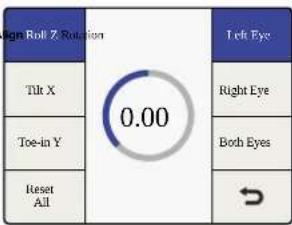
Rotation Menu>Roll Z Axis

Rotation Menu>Tilt X Axis
Roll Adjustment - Z Axis
The 'roll Z' adjustment provides image rotation on the Z axis.
- The range of adjustment on the Z axis is -8 to +8 degrees, with a granularity of 0.02 degrees. The default setting is 0.

Original Image

Roll Z Axis
Tilt Adjustment - X Axis
The 'tilt X' adjustment provides image rotation on the X axis.
- The range of adjustment on the X axis is -8 to +8 degrees, with a granularity of 0.2 degrees. The default setting is 0.

Original Image Tilt X Axis

Toe-In Adjustment - Y Axis
The 'toe-in Y' adjustment provides image rotation on the Y axis.
- The range of adjustment on the Y axis is -8 to +8 degrees, with a granularity of 0.2 degrees. The default setting is 0.

Original Image Toe-in Y Axis


Camera Align>Rotation
Rotation Menu>Toe In Y Axis
![graph TD A["Position"] --> B["ZoomCamera Align"] C["Rotation"] --> D["Trim"] E["Flip"] --> F[" "] G["Reset All"] --> H["⇐"] I["Reset All"] --> J["Off Horizontal"] K["Reset All"] --> L["Vertical Both"] M["Reset All"] --> N["Left Eye"] O["Reset All"] --> P["Right Eye"] Q["Reset All"] --> R["Both Eyes"…](/content/2026/05/812948/images/626fc0d71221574d7d30618c7bf5eceadc541ae1a554d527e4a85c0149e1abdd.jpg)
Camera Align>Flip
Flip Menu>Left Eye / Horizontal
Flip Menu
The 'camera align flip' menu permits you to flip an incoming image horizontally, vertically or in both dimensions simultaneously.
This feature may be used to compensate for inverted cameras mounted in 3D camera rigs that use mirrors or prisms.
- The 'left and right eye' signals may be flipped independently.
- Selecting the 'both eyes' button in the 'flip' menu will simultaneously flip both eyes.
- Pressing 'reset all' will set 'flip' to 'off'.

Original Image Flipped Horizontally


Flipped Vertically

Flipped Both H & V
Zoom Menu
The 'camera align zoom' menu permits you to zoom the left and right images in the horizontal and vertical directions independently, or in both directions simultaneously.
- A negative parameter indicates zooming out on the image, while a positive parameter indicates zooming in on the image.
- Pressing 'both will link the horizontal and vertical zoom parameters, which will maintain the correct aspect ratio while zooming.
- Selecting 'both eyes' will simultaneously zoom both eyes of the stereoscopic image by the same amount.

Camera Align Menu>Zoom
Zoom Menu>Horizontal

Zoom Menu>Vertical
Zoom Menu>Both
Trim Menu
The 'camera align trim' menu permits you to trim the image in the horizontal and vertical directions independently or in both directions simultaneously.
- The range of the trim is dependent on the video format in use.
- In the horizontal direction, the left and right edges will be trimmed simultaneously.
- In the vertical direction, the top and bottom edges will be trimmed simultaneously.
- Pressing 'both' will link the horizontal and vertical trim parameters, which will maintain the correct aspect ratio while trimming.
- Selecting 'both eyes' will allow you to simultaneously trim both eyes of a stereoscopic image by the same amount.

Camera Align Menu>Trim
Trim Menu>Horizontal

Trim Menu>Vertical
Trim Menu>Both
Connections and Other Important Information for 3D Modes
Let's detail some of the connections and ancillary data handling that will affect your workflows.
Video Connections
Stereoscopic left and right video inputs should be connected to SDI inputs A and B respectively. Similarly, left and right processed outputs will be available at SDI outputs A and B respectively. The HDMI input and output connections support full frame 'frame packed' signals.
Video Formats Supported
The 2D to 3D feature supports SD and HD inputs, and converts to an HD output. The '3D convert' and '3D camera align' features support all 3D-centric video formats that are supported by the Teranex 3D. For '3D align', both input streams, left and right, must be of the same format and frame rate. The following video format conversions are supported:
- Input and output video signals up to 1.5Gb/s.
- Pass-through, where the output format is the same as the input format.
- 1080i 50/59.94/60 to 1080p/PsF 23.98/24/25/29.97/30
- 1080p/PsF 23.98/24/25/29.97/30 to 1080i 50/59.94/60
- 1080i 50/59.94/60 to 1080i 50/59.94/60 Frame Rate Conversion
- 1080i 50/59.94/60 to 720p 50/59.94/60
- 720p 50/59.94/60 to 1080i 50/59.94/60
- 720p 50/59.94/60 to 720p 50/59.94/60 Frame Rate Conversion
Independent Channel Processing
Image alignment for each video channel is possible via the 'camera align' application. Proc amp, timecode and noise reduction settings are applied simultaneously to both video streams.
Audio Support
Embedded, AES and Analog audio is supported for 'channel A'. When selecting 'embed', the embedded audio on input A will be processed and outputted via output A.
Ancillary Data Support
Ancillary data such as timecode and AFD is supported on input A and output A only.
External Reference
The output streams may be synchronized to either Input A or to an external reference of black burst or Tri-level sync supplied to the REF connector. Select the type of reference, internal or external, using Home>Reference>Type.
When using an external reference, the interface controls both channel A and B, enabling both output streams to remain pixel locked, even when adjusted relative to the selected reference source.
Capture and Playback
When your Teranex 2D or 3D Processor is connected to a computer via Thunderbolt technology, it can be used as a powerful editing solution for video capture, conversion and playback. This is an efficient way to capture virtually any SD or HD video format for your edit project, whether it is analog, SDI or HDMI. Similarly, you can play back your edit through Teranex for immediate viewing on a monitor or television.
Using your Favorite Editing Software
Some editing software will install plug ins to automatically work with your Teranex, but for others you may need to download and install the latest Blackmagic Design Desktop Video software. This can be downloaded from the Blackmagic Design support center at www.blackmagicdesign.com/support/family/capture-and-playback.
Video Capture
When an application is capturing video, the Teranex LCD will show the word 'capture' followed by the video format of the input signal. For example, 'capture: 1080p24'. Applications including DaVinci Resolve, Avid Media Composer, Apple Final Cut Pro 7, Adobe Premiere Pro CC and Adobe Photoshop CC can all capture video from your Teranex Processor.
Teranex captures the converted video output. Press the 'out' button on your Teranex and check your project or capture preferences match the video format, frame type and frame rate shown by the illuminated buttons.
Batch captures with RS-422 deck control may not be exactly frame accurate because of the conversion processing delay. Accordingly, it is a good idea to use an offset or add handles to your captures. Of course you can also capture without deck control.

Video Playback
When any video application is in playing back a clip, the Teranex Processor LCD will show the word ' playback' followed by the video format. For example, ' playback: 1080p24'. The only illuminated buttons will be those that match the video format being played. All other buttons will be unlit and unavailable as the playback format is set by the clip and so no conversions are allowed. Some applications including Adobe After Effects and Apple Final Cut Pro X are always in playback mode.

The Teranex Installer software installs the Blackmagic Design Desktop Video Control Panel in Mac OS X and Windows.
DaVinci Resolve
You can use DaVinci Resolve to capture both video and audio from your Teranex processor. For example, you could use Teranex to upconvert an old analog videotape and simultaneously capture the HD output with Resolve. Once the clips are captured into Resolve's Media Pool, it's easy to use the powerful editing and color grading tools to further enhance your material.
To capture video using your Teranex processor, you may need to install Blackmagic Design's latest Desktop Video software. You can download the Desktop Video software from the Blackmagic Design website at www.blackmagicdesign.com/support/family/capture-and-playback.
Setting Up
1 Launch 'DaVinci Resolve' and from the 'preferences' menu, select the 'video I/O and GPU' tab and select your Teranex from the 'for capture and playback use' option. Save your preferences and restart DaVinci Resolve to apply your changes.
2 Start a project and from within the 'project settings' window, set your desired 'timeline' and 'monitoring' resolution and frame rate. Your Teranex processor will automatically set its output to match.
3 While you are still in the 'project settings' window, go to the 'capture and playback' tab and select your desired format from the 'video capture and playback' menu.
4 If you are capturing audio, be sure to tick the 'enable audio input' box.
5 In the 'save clips to' option, 'browse' to a location to save your captured media. Click 'save' to confirm your new project settings.
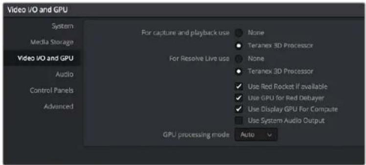
From Preferences select the "Video I/O and GPU" tab and select your Teranex from the "For capture and playback use" option.
Capture
1 From within the 'media' page, click on the 'capture icon' which is located near the top right corner of the software interface.
2 In the 'capture info' window below the 'capture' icon, enter a name for your clip in the 'file name prefix' section. If necessary you can also enter additional information such as 'roll/card', 'reel number', 'clip number', 'program name' or 'good take'.
3 To begin capturing click the 'capture now' button which is located at the bottom of the 'capture info' window. You may need to scroll the window down to reveal the 'capture now' button if you are working on a laptop with a smaller monitor. While capturing, the 'capture info' window will display a 'capture in progress' indicator with a running timecode counter. To stop capturing, click the 'stop' button.

Select your desired format from the "Video capture and playback" menu.
Playback
To playback your clips from the 'media' page, click the 'capture' icon again to close the 'capture info' window. Click on a clip that you have captured to display it in the viewer, then simply click on the viewer transport controls to play your clip.
Editing and Color Grading
Once you've captured your clips, simply click the 'edit' page to begin using DaVinci Resolve's extensive editing features. Then jump to the 'color' page to color grade your clips. You can refer to the DaVinci Resolve manual for detailed information on these features.
Avid Media Composer
Avid Media Composer captures and plays back standard definition and high definition video and audio with Teranex Processor hardware and also supports RS-422 deck control.
For this example, the converted output from Teranex will be 1080i59.94 and we will be capturing from a non-controllable device.
Setting Up
1 Launch Media Composer and the 'select project' window will appear. Click the 'new project' button.
2 In the 'new project' window, name your project.
3 Go to the 'format' dropdown menu and select 1080i/59.94.
4 Go to the 'color space' dropdown menu and select YCbCr 709.
5 Go to the 'raster dimension' dropdown menu and select 1920x1080. Click OK.
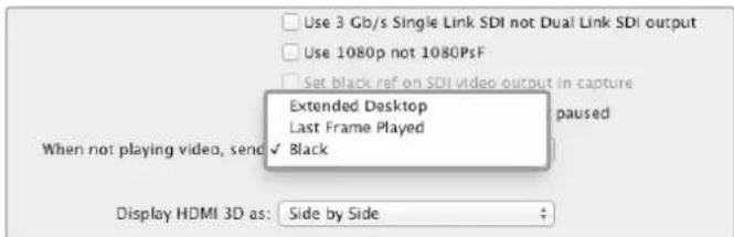
If using a single computer monitor with Media Composer, open the Blackmagic Design system preferences and choose to send Black when not playing video.

Type a project name and set the project options.
Capture
1 Choose Tools > Capture to open the capture tool.
2 Click the 'toggle source' button so that the button's icon of a deck shows a red circle-slash symbol.
3 Set the 'video and audio' input menus to 'Blackmagic'.
4 Select your video and the audio source tracks.
5 Use the 'bin' menu to select a target bin.
6 From the 'res' dropdown menu, choose your codec.
7 Select the 'disk storage' for your captured video and audio.
8 Click the 'tape name' button and select the desired tape and click 'ok'
9 Ensure your video and audio source is ready or playing and then click the 'capture' button.
10 Click the 'capture' button again to stop capturing and close the 'capture' tool.
Playback
You can use the Avid Media Composer timeline to display video on a monitor or TV connected to the output of your Teranex Processor, 'output video' can be toggled on and off by using the 'toggle client monitor' button which is located at the bottom of the timeline window.
Apple Final Cut Pro 7
Blackmagic video hardware is fully compatible with Apple's RT Extreme ® real time effects.
For this example, the converted output from the Teranex will be 1080i50 and we will be capturing from a non-controllable device.
Apple Final Cut Pro 7
Setting Up
1 Launch Final Cut Pro 7 and select File>New Project.
2 Select File>Save Project As... and name your project.
3 From the Final Cut Pro menu, select 'easy setup'...to open the 'easy setup' window.
4 Choose 'HD' for the 'format' and '25.00 fps' for the 'rate'. Select 'Blackmagic HDTV 1080i 50 - 10 bit' from the 'use' menu. Click 'setup' to close the window.
5 From the Final Cut Pro menu, select 'system settings' and with the 'scratch disks' tab highlighted, select 'set' and choose the drive or drives for your scratch disks. Click 'ok'.
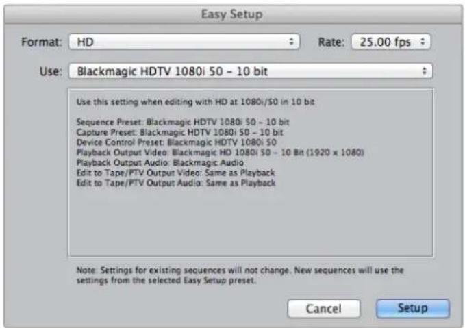
Select a Blackmagic Easy Setup
Capture
1 Choose File > Log and Capture to open the 'log and capture' window.
2 Press 'play' on your video source and then press the 'now' button which is under the 'capture' heading to begin the capturing.
3 Press the 'esc' key at the top left of your keyboard to stop capturing.
4 Choose File > Log and Capture to close the window.
Playback
You can use the Final Cut Pro timeline to display video on a monitor or TV connected to the output of your Teranex Processor. If you can't see any video on your Blackmagic output, check the connections again and ensure you have the correct output settings configured within Final Cut Pro by going to the View > External Video and ensuring 'all frames' is selected.
Apple Final Cut Pro X
If you want to use Final Cut Pro X to play back video on an external video monitor or TV, you can use the broadcast monitoring feature of Final Cut Pro X 10.0.4 and newer to output your video through Teranex Processor hardware.
For this example, clips are Uncompressed 10 bit 4:2:2 1080i59.94 with 2 channels of audio.

Final Cut Pro X
Setting Up
1 Open the 'system preferences' and click on the 'Blackmagic Desktop Video' icon. Click on the round 'setup' icon to open the 'desktop video settings' screen. Set the 'output format' to HD 1080i59.94 and click 'save'.
2 Launch Final Cut Pro X and go to the 'menu' bar and select 'file/new project'. A window will open containing the project setting parameters.
3 Name your project and click the 'use custom settings' button.
4 Under 'video properties', select the 'custom' radio button and set the following: 'format' to HD 1080i, 'resolution' to 1920x1080 and 'rate' to 29.97.
5 Set the 'audio and render properties', by selecting the 'custom' button and set the following: 'audio channels' to stereo, 'audio sample rate' to 48kHz and 'render format' to uncompressed 10 bit 4:2:2. Click 'OK'.
6 Go to the Final Cut Pro menu, choose 'preferences' and then click the 'playback' tab. Ensure the 'A/V output' menu has selected 'Blackmagic' and the same video standard as your project. Close the 'preferences'.
7 Go to the 'window' menu and select 'A/V output' to enable video output via your Teranex processor.
Adobe Premiere Pro CC
For this example, the converted output from the Teranex will be 1080i50 and we will be capturing from a non-controllable device.
Premiere Pro CC 2015.
Setting Up
1 Launch Premiere Pro CC. In the Welcome window select 'create new/new project'. A window will open containing project settings.
2 Name your project. Choose the location for your project by clicking 'browse' and selecting your desired folder.
3 If your graphics card is supported by Premiere Pro CC's Mercury Playback Engine, the 'renderer' option will be available and you should switch it to Mercury Playback Engine GPU Acceleration.
4 Set the 'capture format' to 'Blackmagic capture' and click on the 'settings' button. Set 'video standard' to 1080i50 and select a 'video format' according to your requirements. Click 'OK'.
Playback
1 Import clips into your new project.
2 You can now use the Final Cut Pro X timeline to display video on the monitor or TV connected to the output of your Teranex processor.

Set the Output Format in System Preferences to match your Final Cut Pro X project.

Set the Audio and Render Properties to Custom.
Capture
1 Select File > Capture.
2 Click the 'red record' button to begin capture.
3 Click the 'stop' button to stop capture.
Playback
1 Playback settings need to be selected each time a new project is created. Go to Preferences >Playback and under 'video device', enable the checkbox for 'Blackmagic playback' and ensure the other checkboxes are empty.
2 For audio playback, select 'Blackmagic playback' from the 'audio device' dropdown menu.
3 Click on a clip and you should now see the image on your Teranex Processor.
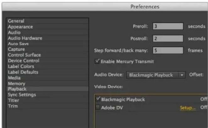
Set preferences for Playback.
Adobe After Effects CC
How to use Blackmagic as a preview output frame buffer
To display your composition in real-time through your Blackmagic hardware, go to Preferences >Video Preview. Mercury Transmit must be enabled in order to use your Blackmagic hardware with After Effects CC. Under Video Devices, select 'Blackmagic playback'.
You can now use a broadcast monitor to view your After Effects compositions in the correct video colorspace. You will always see the correct color and interlace when working, and you don't have to wait until your composition is rendered to see what it looks like when output as video.
If you also want to listen to audio through your Teranex Processor, set the 'default device' to 'Blackmagic audio' in Preferences > Audio Hardware or Preferences > Audio Output Mapping.

After Effects CC 2015.

'Video Preview' preferences
Rendering
When you have completed your composition, you will need to render to a pixel format supported by your Teranex Processor hardware. You can render to a DPX image sequence or any of the following supported codecs:
QuickTime codecs on Mac OS X
- Blackmagic RGB 10 bit uncompressed
- Apple Uncompressed YUV 10 bit 4:2:2
- Apple Uncompressed YUV 8 bit 4:2:2
• Apple Photo - JPEG compressed
• Apple DV - NTSC compressed - Apple DV - PAL compressed
Other codecs including ProRes and DVCPRO HD will be available if you have Final Cut Pro installed.
AVI codecs on Windows
- Blackmagic 10 bit 4:4:4 uncompressed
- Blackmagic 10 bit 4:2:2 uncompressed
- Blackmagic HD 8 bit 4:2:2 uncompressed
- Blackmagic SD 8 bit 4:2:2 uncompressed
- Blackmagic 8 bit MJPEG compressed
Other codecs including DVCPRO HD and DVCPRO50 will be available if you have Premiere Pro CC installed.
QuickTime codecs on Windows
- Blackmagic RGB 10 bit uncompressed
- Blackmagic 10 bit uncompressed
- Blackmagic 8 bit uncompressed
- Apple Photo-JPEG compressed
• Apple DV - NTSC compressed
• Apple DV - PAL compressed

'Output Module Settings' rendering options
Adobe Photoshop CC
How to grab and output video frames
Import an image into Photoshop
1 From Photoshop select File > Import > Blackmagic Image Import.
2 Select the 'video input format' and the 'image bit depth' and then click 'import image'.
Export an image from Photoshop
1 Select File > Export > Blackmagic Image Export.
2 Select 'video output format' and then click 'output image'.
Once you have set the options in the 'import' or 'export' windows, each subsequent 'import' and 'export' will not display the window, so you can grab and output frames much faster. However if you would like to change your import or export formats, hold the 'option' [Mac] or 'ctrl' [Win] key, when selecting import or export.
Photoshop CC 2015.

Image Capture

Image Export
Waveform Monitoring with Blackmagic UltraScope
When Teranex 2D or 3D is connected to a compatible Mac OS X or Windows computer via Thunderbolt, you can use Blackmagic UltraScope to monitor the output levels of your video conversion.
Blackmagic UltraScope software is available to download from the Blackmagic Design support center at www.blackmagicdesign.com/support.
TIP Blackmagic UltraScope is perfect for quality control checks of your converted output no matter which SDI, HDMI, component analog or composite analog video input you use. Simply connect a Thunderbolt cable between your Teranex Processor and your computer and launch Blackmagic UltraScope!
Installation Requirements
The Blackmagic UltraScope software interface requires a computer display with a minimum resolution of 1280 × 800 pixels to view two scopes simultaneously. Blackmagic Design recommends viewing all 6 scopes simultaneously by using a computer display resolution of 1920 × 1200 or 1920 × 1080 pixels.
Please see the support pages at www.blackmagicdesign.com for a comprehensive list of the latest minimum system requirements for Blackmagic UltraScope.
Understanding Blackmagic UltraScope Views
Blackmagic UltraScope has two different views available depending on your workflow needs and screen resolution. You have the choice of viewing six displays in 'full screen' view, or for more compact viewing, choose any 2 displays in '2-up' view.
The display view can be selected from the 'view' menu.
Choose 'full screen' to enter full screen view. If this option is unchecked, 2-up view will be displayed. You can quickly switch between full screen view and '2-up' view by using the hot key 'command F' on Mac OS X.
In '2-up' view, select the desired left and right scopes by opening the 'view' menu or by right-clicking anywhere in the UltraScope window. Make your selections from the 'left view' and 'right view' menu options.
If you want the scopes to swap sides, select the left or right view and set it to be the same as the other view. The scopes will swap sides because the 2-up view never displays the same scope in both the left and right views.
Screen Resolution Requirements for Display Views
- Full Screen view:
1920 x 1200 pixels or 1920 x 1080 pixels. If your monitor doesn't support these resolutions, then 'full screen' view will not be available.
2-up view:
minimum resolution of 1280 x 800 pixels.

Blackmagic UltraScope - Full Screen View

2-Up view
Blackmagic UltraScope Displays
Blackmagic UltraScope software is a great tool for maintaining accurate broadcast legal video and audio levels from your Teranex's converted output. Scopes used to monitor your levels include 'RGB parade', 'waveform', 'vectorscope', 'histogram' and 'audio metering display'.
RGB Parade Display
'RGB parade' displays the red, green and blue channels of your converted output. If one of the color channels appears taller, it usually indicates the presence of a color cast. This may not be desirable and you may want to try minimizing the color cast during post production using color correction software, such as Blackmagic DaVinci Resolve.

RGB Parade Display
Waveform Display
The waveform is great for seeing your black and white levels and overall image contrast. An image with good contrast will display information from 0 IRE to 100 IRE. An image with poor contrast will have the majority of information centered in the display, with little information in the top or bottom areas.
If you are seeing 'milky' or 'gray blacks' on your video display, then they will appear elevated above the 0 IRE line. To adjust the black level, press the 'blk' button on the front of the Teranex and use the rotary knob to lower the black level. If you lower the black level below 0 IRE you will "crush" the image and you risk eliminating shadow detail. Adjust the black level and observe the change on both the monitor and the waveform.
Likewise, if your highlights appear muted or dull, they will appear below the 100 IRE line. To adjust the white level, press the 'gain' button on the front of the Teranex and use the rotary knob to increase the white level. If you raise the level above 100 IRE you will "clip" the image and you risk eliminating highlight detail. Adjust the white level and observe the change on both the monitor and the waveform.
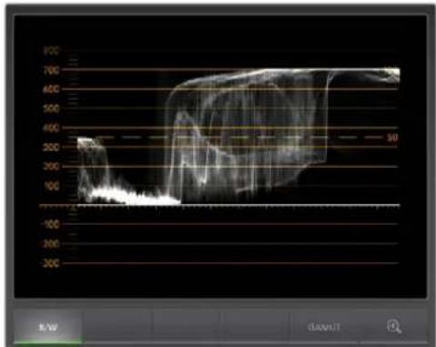
Waveform Display
Vectorscope Display
The Vectorscope is useful for monitoring the color balance and saturation of your Teranex's converted video output. For instance, if your signal has a dominant green color cast then the majority of image information will be located towards the green area of the vectorscope. In comparison, an image with a neutral color balance will have information evenly distributed around the center.

Vectorscope Display
The center of the vectorscope represents zero saturation. The further an object is from the center, the more saturated it appears. If your material appears under or over saturated, press the 'sat' button on your Teranex processor and use the rotary knob to either increase or decrease saturation.
Teranex's 'hue' button can be used if the overall image color appears skewed. As you turn the rotary knob you will see the color information rotate around the vectorscope's center point. Unless the original image has a dramatic color skew, small adjustments will usually be better.
Histogram Display
Using the Histogram is another way to check image contrast. The horizontal axis represents the luminance range with black on the left or 0 in a 10 bit image, and white on the right or 1023 in a 10 bit image. An image with good contrast will display information covering the entire horizontal axis, whereas a low contrast image will display information predominantly in the middle. Use your Teranex processor's 'blk' and 'gain' button settings to make the necessary adjustments.

Histogram Display
Audio Metering Display
Audio metering display shows you the audio levels from your Teranex processor. The audio is displayed in either dBFS or VU format. dBFS is essentially a meter of the overall digital audio signal and is common on modern digital equipment. The VU meter shows average signal levels, is easy to use and very common on older equipment.
To monitor your audio levels, watch the VU meter and ensure the levels never peak above 0dB. Peaking above 0dB means your audio is clipping.
You can also monitor audio phase and balance using the audio metering display.
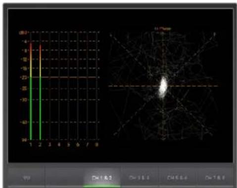
Audio Metering Display
Error Logging Display
'Error logging' records errors in video and audio and is indispensable for unattended operation, such as during long conversions. Errors may be logged for color, brightness or audio threshold levels as well as loss of video signal, change of video format or audio silence. After setting the parameters which define when an error should be logged, you can choose to start or stop error logging, save the log to a file, or clear the log. These functions can be selected from the buttons in the 'error logging display' or from the 'error logging' pulldown menu.
Errors are recorded against timecode and time of day to make them easy to find. If the timecode is not present, errors can be found by reviewing the time of day at which they were recorded.
In the 'full screen' view, 'histogram' and 'error logging displays' share the same area of the UltraScope interface. Select the 'logging' button, below the 'histogram display', to switch to 'error logging display'. Select the 'histogram' button to switch back to the 'histogram display'.
In '2-up' view, 'histogram' and 'error logging displays' can be viewed on two panels simultaneously.
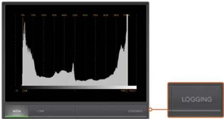
From the Histogram Display, select the Logging button to switch to the Error Logging Display.
Select the 'start' button to commence logging. In 'full screen' view, you can switch back to the 'histogram display' and UltraScope will continue to perform error logging until you choose to stop it.
When error logging is being performed, the 'stop' button replaces the 'start' button. When the 'stop' button has been selected, you can choose to start again and any new errors will be appended to the existing log. When error logging stops, you can choose to save the log to a CSV file or alternatively clear the log. If no errors have been recorded, the 'save' and 'clear' buttons will not appear. The CSV file can be analyzed in many applications including spreadsheet and database software.
By default, error logging is performed using the EBU-R103 standard set by the European Broadcasting Union. This standard is popular worldwide and is commonly used as a template for making new error logging profiles.
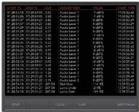
Format Conversion Tables
Teranex AV and Teranex Express
| OUTIN | 525i59.94 NTSC | 625i50 PAL | 720p50 | 720p59.94 | 720p60 | 1080p23.98 | 1080PsF23.98 | 1080p24 | 1080PsF24 | 1080p25 | 1080PsF25 | 1080p29.97 | 1080PsF29.97 | 1080p30 | 1080PsF30 | 1080i50 | 1080i59.94 | 1080p59.94 | 1080i60 | 1080p60 | 2K DCI 23.98p | 2K DCI 23.98PsF | 2K DCI 24p | 2K DCI 24PsF | 2160p23.98 | 2160p24 | 2160p25 | 2160p29.97 | 2160p30 | 2160p50 | 2160p59.94 | 2160p60 |
| 525i59.94 NTSC | ||||||||||||||||||||||||||||||||
| 625i50 PAL | ||||||||||||||||||||||||||||||||
| 720p50 | ||||||||||||||||||||||||||||||||
| 720p59.94 | ||||||||||||||||||||||||||||||||
| 720p60 | ||||||||||||||||||||||||||||||||
| 1080p23.98 | ||||||||||||||||||||||||||||||||
| 1080PsF23.98 | ||||||||||||||||||||||||||||||||
| 1080p24 | ||||||||||||||||||||||||||||||||
| 1080PsF24 | ||||||||||||||||||||||||||||||||
| 1080p25 | ||||||||||||||||||||||||||||||||
| 1080PsF25 | ||||||||||||||||||||||||||||||||
| 1080p29.97 | ||||||||||||||||||||||||||||||||
| 1080PsF29.97 | ||||||||||||||||||||||||||||||||
| 1080p30 | ||||||||||||||||||||||||||||||||
| 1080PsF30 | ||||||||||||||||||||||||||||||||
| 1080i50 | ||||||||||||||||||||||||||||||||
| 1080p50 | ||||||||||||||||||||||||||||||||
| 1080i59.94 | ||||||||||||||||||||||||||||||||
| 1080p59.94 | ||||||||||||||||||||||||||||||||
| 1080i60 | ||||||||||||||||||||||||||||||||
| 1080p60 | ||||||||||||||||||||||||||||||||
| 2K DCI 23.98p | ||||||||||||||||||||||||||||||||
| 2K DCI 23.98PsF | ||||||||||||||||||||||||||||||||
| 2K DCI 24p | ||||||||||||||||||||||||||||||||
| 2K DCI 24PsF | ||||||||||||||||||||||||||||||||
| 2160p23.98 | ||||||||||||||||||||||||||||||||
| 2160p24 | ||||||||||||||||||||||||||||||||
| 2160p25 | ||||||||||||||||||||||||||||||||
| 2160p29.97 | ||||||||||||||||||||||||||||||||
| 2160p30 | ||||||||||||||||||||||||||||||||
| 2160p50 | ||||||||||||||||||||||||||||||||
| 2160p59.94 | ||||||||||||||||||||||||||||||||
| 2160p60 |
Format Conversion Tables
Teranex 2D
| OUTIN | 525i59.94 NTSC | 625i50 PAL | 720p50 | 720p59.94 | 720p60 | 1080p23.98 | 1080PsF23.98 | 1080p24 | 1080PsF24 | 1080p25 | 1080PsF25 | 1080p29.97 | 1080PsF29.97 | 1080p30 | 1080PsF30 | 1080i50 | 1080p50 | 1080i59.94 | 1080p59.94 | 1080i60 | 1080p60 | 2K DCI 23.98p | 2K DCI 23.98PsF | 2K DCI 24p | 2K DCI 24PsF | 2160p23.98 | 2160p24 | 2160p25 | 2160p29.97 | 2160p30 | 2160p50 | 2160p59.94 | 2160p60 | |||||||||||||||||||||||||||||||||||||||||||||||||||||||||||||||||||
| 525i59.94 NTSC | ||||||||||||||||||||||||||||||||||||||||||||||||||||||||||||||||||||||||||||||||||||||||||||||||||||
| 625i50 PAL | ||||||||||||||||||||||||||||||||||||||||||||||||||||||||||||||||||||||||||||||||||||||||||||||||||||
| 720p50 | 2160p50 | |||||||||||||||||||||||||||||||||||||||||||||||||||||||||||||||||||||||||||||||||||||||||||||||||||
| 720p59.94 | ||||||||||||||||||||||||||||||||||||||||||||||||||||||||||||||||||||||||||||||||||||||||||||||||||||
| 720p60 | 1080p23.98 | |||||||||||||||||||||||||||||||||||||||||||||||||||||||||||||||||||||||||||||||||||||||||||||||||||
| 1080p23.98 | ||||||||||||||||||||||||||||||||||||||||||||||||||||||||||||||||||||||||||||||||||||||||||||||||||||
| 1080PsF23.98 | 1080P24 | |||||||||||||||||||||||||||||||||||||||||||||||||||||||||||||||||||||||||||||||||||||||||||||||||||
| 1080p24 | 1080PsF24 | |||||||||||||||||||||||||||||||||||||||||||||||||||||||||||||||||||||||||||||||||||||||||||||||||||
| 1080pF24 | 1080p25 | |||||||||||||||||||||||||||||||||||||||||||||||||||||||||||||||||||||||||||||||||||||||||||||||||||
| 1080p25 | 1080PsF25 | |||||||||||||||||||||||||||||||||||||||||||||||||||||||||||||||||||||||||||||||||||||||||||||||||||
| 1080pF25 | 1080p29.97 | |||||||||||||||||||||||||||||||||||||||||||||||||||||||||||||||||||||||||||||||||||||||||||||||||||
| 1080p29.97 | 1080PsF29.97 | |||||||||||||||||||||||||||||||||||||||||||||||||||||||||||||||||||||||||||||||||||||||||||||||||||
| 1080pF29.97 | 1080p30 | |||||||||||||||||||||||||||||||||||||||||||||||||||||||||||||||||||||||||||||||||||||||||||||||||||
| 1080p30 | 1080PsF30 | |||||||||||||||||||||||||||||||||||||||||||||||||||||||||||||||||||||||||||||||||||||||||||||||||||
| 1080pF30 | 1080i50 | |||||||||||||||||||||||||||||||||||||||||||||||||||||||||||||||||||||||||||||||||||||||||||||||||||
| 1080i50 | 1080p50 | |||||||||||||||||||||||||||||||||||||||||||||||||||||||||||||||||||||||||||||||||||||||||||||||||||
| 1080p50 | 1080i59.94 | 1080p59.94 | 1080i60 | |||||||||||||||||||||||||||||||||||||||||||||||||||||||||||||||||||||||||||||||||||||||||||||||||
| 1080p59.94 | 1080i60 | 1080p60 | 1080p60 | 1080p60 | 1080p60 | 1080p60 | 1080p60 | 1080p60 | 1080p60 | 1080p60 | 1080p60 | 1080p60 | 1080p60 | 1080p60 | [IMAGE] | [IMAGE] | [IMAGE] | [IMAGE] | [IMAGE] | [IMAGE] | [IMAGE] | [IMAGE] | [IMAGE] | [IMAGE] | [IMAGE] | [IMAGE] | [IMAGE] | [IMAGE] | [IMAGE] | [IMAGE] | [IMAGE] | [IMAGE] | [IMAGE] | [IMAGE] | [IMAGE] | [IMAGE] | [IMAGE] | [IMAGE] | [IMAGE] | [IMAGE][IMAGE] | [IMAGE] | [IMAGE] | [IMAGE] | [IMAGE] | [IMAGE] | [IMAGE] | [IMAGE] | [IMAGE] | [IMAGE] | [IMAGE] | [IMAGE] | [IMAGE] | [IMAGE] | [IMAGE] | [IMAGE] | [IMAGE] | [IMAGE] | [IMAGE] | [IMAGE] | [IMAGE] | [IMAGE] | [IMAGE] | [IMAGE] | [IMAGE] | 2160p23.98 | |||||||||||||||||||||||||||||||||||
| 2160p23.98 | 2160p24 | 2160p25 | 2160p29.97 | 2160p30 | 2160p50 | 2160p59.94 | 2160p60 | 2160p60 | 2160p60 | 2160p60 | 2160p60 | 2160p60 | 2160p60 | 2160p60 | 2160p60 | 2160p60 | 2160p60 | 2160p60 | 2160p60 | 21.60p24 | 2160p25 | 2160p29.97 | 2160p30 | 2160p50 | 2160p59.94 | 2160p60 | 2160p60 | 2160p60 | 2160p60 | 2160p60 | 2160p60 | |||||||||||||||||||||||||||||||||||||||||||||||||||||||||||||||||||||
Format Conversion Tables
Teranex 3D
| OUTIN | 525i59.94 NTSC | 625i50 PAL | 720p50 | 720p59.94 | 720p60 | 1080p23.98 | 1080PsF23.98 | 1080p24 | 1080PsF24 | 1080p25 | 1080PsF25 | 1080p29.97 | 1080PsF29.97 | 1080p30 | 1080PsF30 | 1080i50 | 1080p50 | 1080i59.94 | 1080p59.94 | 1080i60 | 1080p60 | 2K DCI 23.98p | 2K DCI 23.98PsF | 2K DCI 24p | 2K DCI 24PsF | 2160p23.98 | 2160p24 | 2160p25 | 2160p29.97 | 2160p30 | 2160p50 | 2160p59.94 | 2160p60 | |||||||||||||||||||||||||||||||||||||||||||||||||||||||||||||||||||
| 525i59.94 NTSC | ||||||||||||||||||||||||||||||||||||||||||||||||||||||||||||||||||||||||||||||||||||||||||||||||||||
| 625i50 PAL | ||||||||||||||||||||||||||||||||||||||||||||||||||||||||||||||||||||||||||||||||||||||||||||||||||||
| 720p50 | 2160p50 | |||||||||||||||||||||||||||||||||||||||||||||||||||||||||||||||||||||||||||||||||||||||||||||||||||
| 720p59.94 | ||||||||||||||||||||||||||||||||||||||||||||||||||||||||||||||||||||||||||||||||||||||||||||||||||||
| 720p60 | 1080p23.98 | |||||||||||||||||||||||||||||||||||||||||||||||||||||||||||||||||||||||||||||||||||||||||||||||||||
| 1080p23.98 | ||||||||||||||||||||||||||||||||||||||||||||||||||||||||||||||||||||||||||||||||||||||||||||||||||||
| 1080PsF23.98 | 1080P24 | |||||||||||||||||||||||||||||||||||||||||||||||||||||||||||||||||||||||||||||||||||||||||||||||||||
| 1080p24 | 1080PsF24 | |||||||||||||||||||||||||||||||||||||||||||||||||||||||||||||||||||||||||||||||||||||||||||||||||||
| 1080PsF24 | 1080p25 | |||||||||||||||||||||||||||||||||||||||||||||||||||||||||||||||||||||||||||||||||||||||||||||||||||
| 1080p25 | 1080PsF25 | |||||||||||||||||||||||||||||||||||||||||||||||||||||||||||||||||||||||||||||||||||||||||||||||||||
| 1080p29.97 | 1080p29.97 | |||||||||||||||||||||||||||||||||||||||||||||||||||||||||||||||||||||||||||||||||||||||||||||||||||
| 1080PsF29.97 | 1080p30 | |||||||||||||||||||||||||||||||||||||||||||||||||||||||||||||||||||||||||||||||||||||||||||||||||||
| 1080p30 | 1080PsF30 | |||||||||||||||||||||||||||||||||||||||||||||||||||||||||||||||||||||||||||||||||||||||||||||||||||
| 1080PsF30 | 1080i50 | |||||||||||||||||||||||||||||||||||||||||||||||||||||||||||||||||||||||||||||||||||||||||||||||||||
| 1080p50 | 1080p59.94 | |||||||||||||||||||||||||||||||||||||||||||||||||||||||||||||||||||||||||||||||||||||||||||||||||||
| 1080p59.94 | 1080p59.94 | |||||||||||||||||||||||||||||||||||||||||||||||||||||||||||||||||||||||||||||||||||||||||||||||||||
| 1080p59.94 | 1080p59.94 | |||||||||||||||||||||||||||||||||||||||||||||||||||||||||||||||||||||||||||||||||||||||||||||||||||
| 1080i60 | 1080p60 | |||||||||||||||||||||||||||||||||||||||||||||||||||||||||||||||||||||||||||||||||||||||||||||||||||
| 1080p60 | 2K DCI 23.98p | |||||||||||||||||||||||||||||||||||||||||||||||||||||||||||||||||||||||||||||||||||||||||||||||||||
| 2K DCI 23.98PsF | ||||||||||||||||||||||||||||||||||||||||||||||||||||||||||||||||||||||||||||||||||||||||||||||||||||
| 2K DCI p24p | ||||||||||||||||||||||||||||||||||||||||||||||||||||||||||||||||||||||||||||||||||||||||||||||||||||
| 2K DCI 42PsF | ||||||||||||||||||||||||||||||||||||||||||||||||||||||||||||||||||||||||||||||||||||||||||||||||||||
| 2160p23.98 | ||||||||||||||||||||||||||||||||||||||||||||||||||||||||||||||||||||||||||||||||||||||||||||||||||||
| 2160p24 | ||||||||||||||||||||||||||||||||||||||||||||||||||||||||||||||||||||||||||||||||||||||||||||||||||||
| 2160p25 | ||||||||||||||||||||||||||||||||||||||||||||||||||||||||||||||||||||||||||||||||||||||||||||||||||||
| 2160p29.97 | ||||||||||||||||||||||||||||||||||||||||||||||||||||||||||||||||||||||||||||||||||||||||||||||||||||
| 2160p30 | ||||||||||||||||||||||||||||||||||||||||||||||||||||||||||||||||||||||||||||||||||||||||||||||||||||
| 2160p50 | ||||||||||||||||||||||||||||||||||||||||||||||||||||||||||||||||||||||||||||||||||||||||||||||||||||
| 2160p59.94 | ||||||||||||||||||||||||||||||||||||||||||||||||||||||||||||||||||||||||||||||||||||||||||||||||||||
| 2160p60 | ||||||||||||||||||||||||||||||||||||||||||||||||||||||||||||||||||||||||||||||||||||||||||||||||||||
DB-25 Connector Pin-outs for the Teranex 2D
Teranex 2D has a pair of RCA inputs so you can connect 2 channels of analog audio for left and right input, but there is also a DB-25 multi pin connector on the rear panel that lets you connect up to 4 analog audio channels, both input and output.
Analog Audio Inputs/Outputs
When you select the 'anlg' button on the front panel as the audio input type, a menu page will appear on the front panel LCD allowing you to choose which of the two analog audio sources you want to use.
When using the DB-25 connector, an optional breakout cable is required, which is a standard Yamaha format cable for balanced XLR connections. This inexpensive breakout cable may be purchased through many vendors, or may be fabricated using off the shelf connectors and cable.

DB-25 pin outs also compatible with Yamaha™, Mackie™, Sony™ and Apogee™ connectors.
| AnalogAudio Channel Hot Pins (+) Cold Pins (−) Ground Pins | |||
| 1 IN 1 14 10 | |||
| 2 IN 2 15 12 | |||
| 3 IN 3 16 13 | |||
| 4 IN 4 17 22 | |||
| 1 OUT | 5 18 23 | ||
| 2 OUT | 6 | 19 | 24 |
| 3 OUT | 7 | 20 | 25 |
| 4 OUT | 8 | 21 | 25 |
Teranex 2D Processor analog audio pin connections.
AES/EBU Audio Inputs/Outputs
Press the 'AES' button on the Teranex 2D front panel to select the AES/EBU digital audio input. The AES/EBU output is always active.
A DB-25 connector is used for connecting up to 8 input channels made up of 4 pairs and 8 output channels made up of 4 pairs of balanced, AES/EBU digital audio to the Teranex 2D Processor.
An optional breakout cable is required, which is a standard Yamaha format cable for balanced XLR connections. This inexpensive breakout cable may be purchased through many vendors, or may be fabricated using off the shelf connectors and cable.

DB-25 pin outs also compatible with Yamaha™, Mackie™, Sony™ and Apogee™ connectors.
| AnalogAudio Channel Hot Pins (+) Cold Pins (−) Ground Pins | |||
| 1&2 IN 1 14 10 | |||
| 3&4 IN 2 15 12 | |||
| 5&6 IN 3 16 13 | |||
| 7&8 IN 4 17 22 | |||
| 1&2 OUT | 5 18 23 | ||
| 3&4 OUT | 6 | 19 | 24 |
| 5&6 OUT | 7 | 20 | 25 |
| 7&8 OUT | 8 | 21 | 25 |
Teranex 2D Processor AES/EBU audio pin connections.
Installing Optional Blackmagic Design Fiber Optic SFP
Blackmagic Teranex AV and Teranex Express have a built in optical fiber cage so you can install an optional optical fiber SFP module. When the SFP module is installed, you can reliably connect video signals up to 12G-SDI over longer distances than coaxial cable can provide.
Installing the optional Blackmagic Design Fiber Optic SFP in your Teranex Express Processor
WARNING
Precautions should be taken to reduce the risk of electrostatic discharge while installing the SFP module.
Installing or removing the Module
The Blackmagic Design fiber optic SFP module has a clasp to assist you in removing or installing the module. The module is “hot-pluggable,” meaning that it may be installed or removed without powering down your Teranex.
The Blackmagic Design SFP supports single mode optical fiber with LC connectors. It is bi-directional, supporting video formats up to Ultra HD 2160p60.

Blackmagic Design SFP Module
To install the Blackmagic Design SFP Module:
1 Close the clasp before inserting the SFP module.
2 Remove the cage cover from the optical module cage on the rear panel of your Teranex.
3 Line up the SFP module with the optical module cage and slide it into the cage. Verify that the SFP module is completely seated and secured in the cage by firmly pushing on the SFP module.
4 If a dust protector is present on the SFP module, leave it in place until you are ready to install your fiber optic cables.
To remove the Blackmagic Design SFP Module:
1 Disconnect all fiber optic cables from the SFP.
2 Open the clasp on the SFP module with your index finger or a small, flat-blade screwdriver.
3 Grasp the SFP module and carefully remove it from the cage.
4 Immediately place the SFP module in a static shielding bag.
5 Insert an SFP module cage cover into the optical module cage of your Teranex when no SFP module is installed.

Installing the SFP Module into the Teranex Express.
Teranex AV Chassis Bumpers
Teranex AV is supplied with two chassis bumpers that can be attached to each side of the chassis. These bumpers are designed to protect the connectors on the rear panel from potential damage when using in portable, outside broadcast, or field work. They can also provide strain relief for cables that are connected to the unit.
The chassis bumpers should be attached to the Teranex AV using the four M4 screws included with your unit. A pair of M4 mounting holes is provided on each side of the Teranex AV.

Attach the supplied bumpers to each side of your Teranex AV.
Developer Information
Developing Custom Software using Blackmagic Design Hardware
The DeckLink SDK is available for developers to control Blackmagic video hardware with their own custom software and supports the Teranex, UltraStudio, DeckLink, Multibridge and Intensity families of products. The SDK provides both low level control of hardware and high level interfaces to allow developers to easily perform common tasks.
The DeckLink SDK supports the following technologies:
- Apple QuickTime
- Apple Core Media
- Microsoft DirectShow
- DeckLink API
Downloading the Free Blackmagic Design SDK
The DeckLink SDK can be downloaded from the 'capture and playback' section of the Blackmagic Design support center at www.blackmagicdesign.com/support.

Joining the Blackmagic Design Software Developers Forum
If you're looking for answers, feedback or suggestions regarding technologies used by Blackmagic Design, such as codecs, core media, APIs, SDK and more, visit the Blackmagic Design Software Developers forum. The forum is a helpful place for you to engage with both Blackmagic Design support staff and other forum members who can answer developer specific questions and provide further information. The Software Developers forum can be found within the Blackmagic Design Forum at: https://forum.blackmagicdesign.com
Contacting Blackmagic Design Developer Assistance
If you wish to ask questions outside of the Blackmagic Design Software Developers forum, please contact us at: developer@blackmagicdesign.com
Blackmagic Teranex Ethernet Protocol
Protocol Details
Overview
The Blackmagic Teranex Ethernet Protocol is a line-oriented, text-based protocol. Lines from the Teranex Ethernet server will be separated by an ASCII CR LF sequence.
Messages from the user may be separated by LF or CR LF.
New lines are represented in this document by the “←” symbol.
Connection
The Blackmagic Teranex Ethernet Server listens on TCP port 9800. In a Telnet session, type in "telnet" and a space, followed by the IP address of your Teranex, another space and "9800". For example: telnet 192.168.90.236 9800
Connection Response
Upon connection, the Teranex Server sends a complete dump of the state of the device.
The Teranex Server sends information in blocks, with each having an identifying header in all-caps, followed by a full-colon. A block spans multiple lines and is terminated by a blank line. Each line in the protocol is terminated by a newline character.
The protocol preamble block is always the first block sent by the Teranex Server, followed by the device block:
PROTOCOL PREAMBLE:←
Version: 1.13
TERANEX DEVICE:←
Model name: Teranex 2D←
After the initial status dump, status updates are sent each time the status changes in the Teranex device.
Legend
carriage return
... and so on
Orange text Client generated
Grey Text Server generated
Command Syntax
To initiate a change, the user should send the appropriate block header, followed by a full-colon and LF, which is then followed by the specific command requested, a full-colon, the value required, a LF, followed by a blank line. For example, to change the output video format to 1080i59.94, the user should send the following block of commands:
VIDEO OUTPUT
Video mode: 1080i5994
Response Syntax
If the command is accepted by the Teranex Server, it will respond with an ACK message. If the request was not understood, it will respond with a NACK message.
After a positive response, the user should expect to see a status update from the Teranex Server showing the status change. This is likely to be the same as the command that was sent, sometimes followed by other blocks providing data specific to the change. For the above example, the following response might be displayed:
VIDEO OUTPUT
Video mode: 1080i5994←
VIDEO ADJUST:←
Luma low: 4←
Luma high: 1019←
...
ANCILLARY DATA←
AFD output line: 11←
CC enabled: false←
...
VARIABLE ASPECT RATIO:←
Variable Aspect Ratio size X left: 0.000000
Variable Aspect Ratio size X right: 0.000000
...
The asynchronous nature of the responses means that a user should never rely on the desired update actually occurring and must simply watch for status updates from the Teranex Server and use only these to update its local representation of the server state.
Timecode Syntax
Timecode values are expressed as HH:MM:SS:FF.
Checking Connection Status
While the connection to the Teranex Server is established, a user may send a special no-operation command to check that the Teranex Server is still responding. In this case, a blank line is not required following the command:
PING:
If the Teranex Server is responding, it will respond with an ACK message as it does for any other recognized command.
Closing Connection
To end a Telnet session in Mac, Windows or Linux, press and hold the Control (Ctrl) key and press the ‘]’ right bracket key, release the Control key, type quit and press the ‘Enter’ key. For example:
<C N T L>+]
quit
Status Updates
When any parameter in the Teranex device is changed on the Teranex Server by any user, the Teranex Server resends the applicable status block, containing only the items that have changed. For example, if the output aspect ratio is changed to CentreCut, the following block will be sent:
VIDEO OUTPUT
Aspect ratio: CentreCut
Requesting a Status Dump
The user may request that the Teranex Server resend the complete state of any status block by sending the header of the block, a LF, followed by a blank line. In the following example, the user requests the Teranex Server resend the Video Output status:
VIDEO OUTPUT
ACK←
←
VIDEO OUTPUT←
Video mode: 1080i5994←
Aspect ratio: Anamorphic←
Video demux mode: SingleLink←
Video pixel format: YCbCr422←
Analog output: Component←
←
Retrieving Device Information
The "Teranex Device" command returns information about the connected device:
TERANEX DEVICE:
The server will respond with:
TERANEX DEVICE:
Model name: (displays the Teranex model name)
Software Version: (displays the checksum of the installed software release)
FPGA Version: (displays the FPGA version of the installed software release)
Protocol Commands
Align
The Align commands are available in the Teranex 3D only. They may be used to adjust the alignment between 3D stereoscopic left and right eye signals. In the Teranex 3D LCD menus, these functions are included in the “Camera Align” menus. Size (Zoom), Position and Trim commands are included in this block. Other Camera Align functions, Flip and Rotation, are found in the Mode3D command block.
To use the Align commands, the Teranex 3D must be receiving left and right eye video signals and must be in the 3D Align mode. Enter the commands below and then proceed with adjustments via the Align commands.
MODE3D: ←
3D mode: 3DModeAlign ←
ACK←
MODE3D: ←
3D mode: 3DModeAlign ←
...
Size (Zoom), Position and Trim Commands
The commands below permit you to adjust the left and right eye signals independently.
For example, the "Align pos X left:" adjusts the horizontal position of the left eye, whereas
"Align pos X right:" adjusts the horizontal position of the right eye. For example, to move the position of the left eye 20 pixels to the right enter:
A LIG N↓
Align pos X left: -20↓
←
ACK←
←
A LIG N↓
Align pos X left: -20.000000←
Align pos X right: 0.000000←
Align pos Y left: 0.000000←
Align pos Y right: 0.000000←
←
Protocol Commands
| Command Command Description | |
| Align size X left: 0.000000 Set the | Horizontal Size (X) (Zoom) value for the Left Eye.Negative values decrease size; positive values enlarge the image. Default = 0 |
| Align size X right: 0.000000 Set the | Horizontal (X) Size (Zoom) value for the Right Eye.Negative values decrease size; positive values enlarge the image. Default = 0 |
| Align size Y left: 0.000000 Set the | Vertical (Y) Size (Zoom) value for the Left Eye.Negative values decrease size; positive values enlarge the image. Default = 0 |
| Align size Y right: 0.000000 Set the | Vertical (Y) Size (Zoom) value for the Right Eye.Negative values decrease size; positive values enlarge the image. Default = 0 |
| Align pos X left: 0.000000 Set the | Horizontal (X) Position value for the Left Eye.Negative values move the image to the right; positive values move the image to the left. Default = 0 |
| Align pos X right: 0.000000 Set the | Horizontal (X) Position value for Right Eye. Negative values move the image to the right; positive values move the image to the left. Default = 0 |
| Align pos Y left: 0.000000 Set the | Vertical (Y) Position value for the Left Eye. Negative values move the image down; positive values move the image up. Default = 0 |
| Align pos Y right: 0.000000 | Set the Vertical (Y) Position value for the Right Eye. Negative values move the image down; positive values move the image up. Default = 0 |
| Align trim X left: 0 Set the Horizontal | (X) Trim value for the Left Eye; performs symmetrical adjustment on the right and left sides of the image. Default = 0 |
| Align trim X right: 0 Set the Horizontal | (X) Trim value for the Right Eye; performs symmetrical adjustment on the right and left sides of the image. Default = 0 |
| Align trim Y left: 0 Set the Vertical (Y) | Trim value for the Left Eye; performs symmetrical adjustment on the top and bottom of the image. Default = 0 |
| Align trim Y right: 0 Set the Vertical (Y) | Trim value for the Right Eye; performs symmetrical adjustment on the top and bottom of the image. Default = 0 |
Ancillary Data
Teranex processors support closed captions, timecode and video indexing in the ancillary data.
Closed Captions
| Command Command Description | |
| CC enabled: Enable Closed Caption processing. True=ON; False=OFF;(Default = False) | |
| CC input line: Analog CC input line selection. Range is 20 to 22.Default = 21 | |
| CC output line: Analog CC output line selection. Range is 20 to 22.Default = 21 | |
| CC service2 source: CC Service 2 selection; Values are CC2 (default) or CC3 | |
| CC service1 language: | Service 1 Language selection. Values are:English (default), French, German, Italian, Spanish |
| CC service2 language: | Service 2 Language selection. Values are:English (default), French, German, Italian, Spanish |
Timecode
| Command Command Description | |
| Timecode mode: Select the mode of the timecode generator. Values are:Off, Input, InputRegen, Generate, JamSync | |
| Timecode input line: Set the line on which the input timecode is located. The valid range of values is format dependent. To set the unit to the default automatic input detection mode, enter 0.NTSC: lines 10-20PAL: lines 6-221080 HD: lines 9-20720 HD: lines 9-25 | |
| Timecode output line: Set the line on which the output timecode is located. The valid range of values is format dependent. To set the unit to the default output line, enter 0.NTSC: lines 10-20 (Default = 14)PAL: lines 6-22 (Default = 19)1080 HD: lines 9-20 (Default = 9)720 HD: lines 9-25 (Default = 9) | |
| Timecode drop frame mode: Change the drop frame mode in valid output formats.Values are: DF, NDF. | |
| Timecode source: This command is only needed for the Teranex 3D.Values are: VITC, LTC. | |
| Timecode generate value: Set the start time of the output timecode generator, expressed as HH:MM:SS:FF | |
| Timecode jam sync value: | Set the search value for the Jam Sync generator, expressed as HH:MM:SS:FF |
| Timecode start source: | Set the source of the timecode number used by the generator. Values are: Input, User (where “User” is equivalent to “Start Value” in the LCD Menu tree). |
Video Indexing
Command Command Description
Index reaction: Values are: On, Off (Default = Off)
AFD insert type: Values are: Off, Auto, Bypass, or AFD codes 0000 - 1111. For
details, see the AFD Insertion Menu topic in the user manual.
AFD output line: Range is format dependent. For details, see the AFD Insert
Line Menu topic in the user manual.
Audio
Audio output selections and adjustments are made in the Audio block. Please note, however, audio input selection is made in the Video Input block via the Audio source: command. In Teranex 2D, audio input mapping is available, permitting audio from 'embed', 'AES' and 'anlg' inputs simultaneously, with certain limitations. For details, see 'input mapping' in the 'audio menu settings' section of this manual.
Setup
Command Command Description
AES output select: Select between AES or Analog audio output on the Teranex
3D XLR connectors. True=AES; False=Analog
Analog input ref level: Set the Analog Input Reference Level for Teranex 2D and 3D.
Values are: -24 to +24. Default =0. The operational range in dB is -12 to +12dB. e.g. For +4db, enter a value of 8.
Audio meter channels; This command selects the pair of audio channels to be
displayed on the front panel LCD in the Teranex AV only.
Level (Gain) and Delay
Command Command Description
AudioUserDelay0: Set audio delay for all channels to same value.
Enter value as a whole number in milliseconds.
Range is -28 to +1000 msec. Default = 0.
In the Teranex 2D and Express:
Command Command Description
AudioInLevel0: Set audio level (gain) for ALL channels to same value. Enter the
value as a whole number of gain in dB times 10 (e.g. For +4dB, enter a value of 40). Range is -32dB (-320) to +16dB (160). Default =0.
In the Teranex 3D, you can adjust the level of each channel independently:
Command Command Description
AudioInLevel0: Set audio level (gain) for Channel 1
AudioInLevel1: Set audio level (gain) for Channel 2
| Command Command Description |
| AudioInLevel2: Set audio level (gain) for Channel 3 |
| AudioInLevel3: Set audio level (gain) for Channel 4 |
| AudioInLevel4: Set audio level (gain) for Channel 5 |
| AudioInLevel5: Set audio level (gain) for Channel 6 |
| AudioInLevel6: Set audio level (gain) for Channel 7 |
| AudioInLevel7: Set audio level (gain) for Channel 8 |
| AudioInLevel8: Set audio level (gain) for Channel 9 |
| AudioInLevel9: Set audio level (gain) for Channel 10 |
| AudioInLevel10: Set audio level (gain) for Channel 11 |
| AudioInLevel11: Set audio level (gain) for Channel 12 |
| AudioInLevel12: Set audio level (gain) for Channel 13 |
| AudioInLevel13: Set audio level (gain) for Channel 14 |
| AudioInLevel14: Set audio level (gain) for Channel 15 |
| AudioInLevel15: Set audio level (gain) for Channel 16 |
Enter the value as a whole number of gain in dB times 10 (e.g. For +4dB, enter a value of 40). Range is -32dB (-320) to +16dB (160). Default =0.
Output Mapping
You may choose any active audio input channel, Dolby-decoded channel, test tone or mute to be mapped to each discrete audio output channel or Dolby-encoded output channel. Dolby encoding and decoding require optional Dolby modules, which can be installed in the Teranex 3D only.
Available source values are:
| Command Command Description |
| Inputs: Audioln1 through Audioln16 |
| Dolby decoded inputs: AudioDD1 through AudioDD8 |
| Test tones: TT750 (750kHz), TT1500 (1.5 kHz), TT3000 (3kHz), TT6000 (6kHz), TTMute |
Please note: AudioOut0: refers to output channel 1, AudioOut1: refers to output channel 2, etc.
| Command Command Description | |
| AudioOut0: | Select source to be mapped to output Ch 1. |
| AudioOut1: Select source to be mapped to output Ch 2. | |
| AudioOut2: | Select source to be mapped to output Ch 3. |
| AudioOut3: Select source to be mapped to output Ch 4. | |
Command Command Description
AudioOut4: Select source to be mapped to output Ch 5.
AudioOut5: Select source to be mapped to output Ch 6.
AudioOut6: Select source to be mapped to output Ch 7.
AudioOut7: Select source to be mapped to output Ch 8.
AudioOut8: Select source to be mapped to output Ch 9.
AudioOut9: Select source to be mapped to output Ch 10.
AudioOut10: Select source to be mapped to output Ch 11.
AudioOut11: Select source to be mapped to output Ch 12.
AudioOut12: Select source to be mapped to output Ch 13.
AudioOut13: Select source to be mapped to output Ch 14.
AudioOut14: Select source to be mapped to output Ch 15.
AudioOut15: Select source to be mapped to output Ch 16.
AudioEncode0: Select source to be mapped to Ch 1 of Dolby Encoder
AudioEncode1: Select source to be mapped to Ch 2 of Dolby Encoder
AudioEncode2: Select source to be mapped to Ch 3 of Dolby Encoder
AudioEncode3: Select source to be mapped to Ch 4 of Dolby Encoder
AudioEncode4: Select source to be mapped to Ch 5 of Dolby Encoder
AudioEncode5: Select source to be mapped to Ch 6 of Dolby Encoder
AudioEncode6: Select source to be mapped to Ch 7 of Dolby Encoder
AudioEncode7: Select source to be mapped to Ch 8 of Dolby Encoder
You may choose audio pairs from embedded, AES, analog DB25 or analog RCA inputs to be mapped to the 16 input channels of the Teranex 2D. You may also mute audio pairs.
Available source values are:
| Inputs: EmbedPair1 through EmbedPair8 | |
| AESPair1 through AESPair4 | |
| DB25Pair1 through DB25Pair2 | |
| RCAPair | |
| MutePair | |
Please note: AudiolnPair0: refers to input pair 1, AudiolnPair1: refers to input pair 2, etc.
| Command Command Description |
| AudiolnPair0: Select source to be mapped to input pair 1 |
| AudiolnPair1: Select source to be mapped to input pair 2 |
| AudiolnPair2: Select source to be mapped to input pair 3 |
| AudiolnPair3: Select source to be mapped to input pair 4 |
| AudiolnPair4: Select source to be mapped to input pair 5 |
| AudiolnPair5: Select source to be mapped to input pair 6 |
| AudiolnPair6: Select source to be mapped to input pair 7 |
| AudiolnPair7: Select source to be mapped to input pair 8 |
Metadata Commands for Teranex 3D
Available source values are:
| Command Command Description |
| Metadata channel mode: Values are: 32 (3/2 (L,C,R,Ls,Rs)), 20 (2/0 (L/R)) |
| Metadata lfe select: Enables LFE. False=OFF; True=ON |
Genlock
| Command Command Description | |
| Gen reference: For Teranex AV only. | Select the Reference Output signal.The type of output allowed is dependent on the currently selected output format, the values are: Blackburst, TriLevel. |
| Line offset: Set line timing adjustment for external genlock.Values are within the range set by the current output video format. (Default = 1) | |
| Pixel offset: Set pixel timing adjustment for external genlock. Values arewithin the range set by the current output video format.(Default = 0) | |
| Signal locked: Indicate genlock status. Cannot be changed by the end user.True indicates that the Teranex processor is locked to the external reference. False indicates that it is not locked. | |
| Type: | Select the Genlock (Reference) source for the device.For Teranex 2D, 3D and Express, values are: Input, External.For Teranex AV, values are: Input, External and Internal. |
MODE3D
The MODE3D commands are available in the Teranex 3D only. See the "3D Menu Settings" section of this user manual for details.
Example:
MODE3D: ←
3D MODE: 3DModeAlign ←
←
ACK←
←
MODE3D: ←
3D mode: 3DModeAlign ←
3D roll left: 0←
...
←
A LIG N↓
Align size X left: 0.00
Align size X right: 0.0
...
←
Mode, Input and Output Commands
| Command Command Description | |
| 3D mode: Enable the 3D processing modes of the Teranex 3D.Values are: 3DModeOff, 3DModeConvert, 3DMode2Dto3D, 3DModeAlign | |
| 2D3D intensity: Adjust the Intensity level when 3D Mode is set to2D to 3D. Range is --40 to +40. (Default = 15) | |
| 2D3D depth: Adjust the Depth level when 3D Mode is set to2D to 3D. Range is -12 to +12. (Default = 0) | |
| 3D output: Select the 3D output signal format: Values are: 3DFullFrame,3DSideBySide, 3DTopBottom, 3DLinebyLine | |
| 3D input: Select the 3D input signal format: Values are: 3DFullFrame,3DSideBySide, 3DTopBottom, 3DLinebyLine |
Rotation and Tilt Commands
The commands below may be used to adjust the alignment between the left and right eye signals of a 3D stereoscopic source. In the Teranex 3D LCD menus, these functions are part of the "Camera Align" menu.
Rotation (Roll, Tilt and Toe-in) and Flip commands are included in this block. Other Camera Align functions, Size, Position and Trim, are found in the Align block.
First, enter the "MODE3D:" block command, then use the "3D mode:" command to select "3DModeAlign" and proceed with the adjustment commands below.
Example:
MODE3D: ←
3D roll left: 2Q
ACK ←
MODE3D: ←
3D roll left: 20 ←
3D roll right: 0 ←
| Command Command Description | |
| 3D roll left: Adjust the Left Eye Z axis image rotation. | |
| 3D roll right: Adjust the Right Eye Z axis image rotation. | |
| 3D tilt left: Adjust the Left Eye X axis image tilt. | |
| 3D tilt right: Adjust the Right Eye X axis image tilt. | |
| 3D toeln left: Adjust the Left Eye Y axis image toe-in. | |
| 3D toeln right: Adjust the Right Eye Y axis image toe-in. | |
| 3D flip left: Flip the Left Eye image. Values are: | |
| 3D flip right: Flip the Right Eye image. Values are: | |
Network Config
| Command Command Description | |
| Friendly name: Displays the current user-defined name assigned to the device. Command is used to assign a new name to the device. | |
| DHCP enabled: Although not advised, user may enable/disable DHCP. True = enabled; False = disabled | |
| IP address: Displays current IP address as an integer. | |
| Cannot be changed by the user. | |
| Gateway: Displays current gateway as an integer. | |
| Cannot be changed by the user. | |
| Subnet: Displays current subnet mask as an integer. | |
| Cannot be changed by the user. | |
Noise Reduction
| Command Command Description |
| Enabled: Enable Noise Reduction. False = OFF; True = ON |
| Bias: Adjust the Bias level. Range is -3 to +3 |
| Split screen: Enable NR before/after split screen. False = OFF; True = ON |
| Red overlay: Enable NR Red Overlay. False = OFF; True = ON |
Ping
Determine if the Teranex Server is responding.
Preset
Please note: PresetName0: refers to Preset 1, PresetName1: refers to Preset 2, etc.
| Command Command Description | |
| PresetName0: Displays all current user-defined preset names. | Command is used to assign a new name to Preset 1. |
| PresetName1: Displays all current user-defined preset names. | Command is used to assign a new name to Preset 2. |
| PresetName2: Displays all current user-defined preset names. | Command is used to assign a new name to Preset 3. |
| PresetName3: Displays all current user-defined preset names. | Command is used to assign a new name to Preset 4. |
| PresetName4: Displays all current user-defined preset names. | Command is used to assign a new name to Preset 5. |
| PresetName5: Displays all current user-defined preset names. | Command is used to assign a new name to Preset 6. |
| Recall: Recalls a previously saved preset, 1-6. (e.g. Recall: 1) | |
| Save: Saves a new set of parameters to the designated preset, 1-6. (e.g. Save: 1) | |
Protocol Preamble
The Teranex Server will respond with the current protocol version.
This information cannot be changed by the user.
PROTOCOL PREAMBLE:
Version: 3.18
Teranex Device
| Command Command Description | |
| Model name: Display the Teranex model name. | |
| Software Version: Display the checksum of the installed software release. | |
| FPGA Version: Display the FPGA version of the installed software release. | |
| Panel lock: Remotely lock the front panel of the device, preventing local operation. Values are: true (locks the panel), false (unlocks the panel). | |
| Remote lock: Manage remote connections to the Teranex processor. | |
| When locked, the Teranex Setup utility cannot access the device via Ethernet; however, a Telnet connection is permitted. Values are: true (locks the device), false (unlocks the device). | |
Test Pattern
| Command Command Description | |
| Output: Enable video output Test Pattern. Values are: None, Black,SMPTEBars, Bars, Multiburst, Grid | |
| No signal: Define whether Black or Colorbars will be output when thereis a loss of input video. Values are Black, Bars | |
| Test tone: This command enables and sets the frequency for the audiotest tone in the Teranex AV only. This command is only validwhen a video test pattern is enabled. Values are: None,Tone750Hz, Tone1500Hz, Tone3KHz, Tone6KHz | |
| Motion: For Teranex AV only. Enable test pattern motion.True = ON;False = OFF | |
| Horizontal rate: For Teranex AV only. Set motion direction and rate.0 = no motion (default)Range is -3 to 3, where:Positive values = left to right motionNegative values = right to left motion |
Variable Aspect Ratio
The Variable Aspect Ratio block performs the functions of the ADJ menu in the Teranex LCD menu. Ranges for these numeric values are defined by the current output video format. Horizontal values are expressed in pixels; vertical values are in lines.
The Variable Aspect Ratio commands ending in "left" will affect the conventional 2D outputs of the Teranex AV, Teranex Express, Teranex 2D and Teranex 3D, while the "right" commands perform no operation. When these commands are used in a Teranex 3D set to 3DModeConvert or 3DMode2Dto3D, the "left" commands will affect the Left Eye output, while the "right" commands will affect the Right Eye output.
| Command Command Description | |
| Variable Aspect Ratio size X left: Adjust horizontal image size. Negative values decrease size; positive values enlarge the image. Default = 0 | |
| Variable Aspect Ratio size X right: Adjust horizontal image size of the Teranex 3D right eye output. Negative values decrease size; positive values enlarge the image. Default = 0 | |
| Variable Aspect Ratio size Y left: Adjust vertical image size. Negative values decrease size; positive values enlarge the image. Default = 0 | |
| Variable Aspect Ratio size Y right: Adjust vertical image size of the Teranex 3D right eye output. Negative values decrease size; positive values enlarge the image. Default = 0 | |
| Variable Aspect Ratio pos X left: Adjust horizontal position of the image. Negative values move the image to the left; positive values, to the right. Default = 0 | |
| Variable Aspect Ratio pos X right: Adjust horizontal position of the Teranex 3D right eye output. Negative values move the image to the left; positive values, to the right. Default = 0 | |
| Variable Aspect Ratio pos Y left: Adjust vertical position of the image. Negative values move the image upward; positive values, downward. Default = 0 | |
| Variable Aspect Ratio pos Y right: Adjust vertical position of the Teranex 3D right eye output. Negative values move the image upward; positive values, downward. Default = 0 | |
| Variable Aspect Ratio trim X left: Trim the sides of the image. Default = 0 | |
| Variable Aspect Ratio trim X right: | Trim the sides of the Teranex 3D right eye output. Default = 0 |
| Variable Aspect Ratio trim Y left: Trim the top and bottom of the image. Default = 0 | |
| Variable Aspect Ratio trim Y right: Trim the top and bottom of the Teranex 3D right eye output. Default = 0 | |
| Variable Aspect Ratio zoom/crop: Enables Zoom/Crop. False=OFF; True=ON (Default = False) | |
Video Adjust
| Command Command Description | |
| Red: Set value of Red color correction control. | Range is -200 to +200 (Default = 0) |
| Green: Set value of Green color correction control. | Range is -200 to +200 (Default = 0) |
| Blue: Set value of Blue color correction control. | Range is -200 to +200 (Default = 0) |
| Luma low: Set luminance low level value to clip undershoots. | Range is 4 to 1018 (Default = 4) |
| Luma high: Set luminance high level | value to clip overshoots. Range is 5 to 1019 (Default = 1019) |
| Chroma low: Set chrominance low level | value to clip undershoots. Range is 4 to 1018 (Default = 4) |
| Chroma high: Set chrominance high | level value to clip overshoots. Range is 5 to 1019 (Default = 1019) |
| Aspect fill luma: Set luminance (Y) | value for letterbox or pillarbox fill color. Range is 64 to 940 (Default = 64) |
| Aspect fill Cb: Set B-Y value for letterbox or pillarbox fill color. Range is 64 to 960 (Default = 512) | |
| Aspect fill Cr: Set R-Y value for letterbox or pillarbox fill color. Range is 64 to 960 (Default = 512) | |
Video Advanced
| Command Command Description | |
| Clean cadence: Enable Clean Cadence processing. False = OFF;True = ON (Default = False) | |
| Scenecut detect: Enable scene cut detection. False = OFF;True = ON (Default = True) | |
| Source type: Values are: Auto, Video, Film | |
| FRC aperture: Values 0, 1, 2, 3. | |
| Processing: This command sets the processing latency in the Teranex AVonly. Values are: Lowest Latency, Highest Quality. |
Video Input
| Command Command Description | |
| Auto detection enabled: Provides auto-detection of the input video format. Must ALWAYS be set to True. A setting of False will produce incorrect operation of the device. | |
| Auto detection prefer PsF: Cannot be changed by the user. | |
| Video source: Select the video input type. Values are model dependent.Teranex 2D: SDI, HDMI, Composite, Component.Teranex 3D: SDI, HDMI, Composite, ComponentTeranex Express: SDI, Optical.Teranex AV: SDI1, SDI2, HDMI, Optical. | |
| Video mode: | Displays the current input video format.Cannot be changed by the user. |
| Audio source: Select the audio input type. Values are model dependent.Teranex 2D: Embedded, AES, RCA, DB25.Teranex 3D: Embedded, AES, RCA, DB25.Teranex Express: Embedded.Teranex AV: Embedded, AES, RCA, DB25. | |
| PCIe mode: For Teranex 2D and 3D: Display the status of the Thunderbolt connection. Values are: Capture, Playback, NoneCannot be changed by the user. | |
| Signal present: True indicates presence of input video.False indicates no input video is present.Cannot be changed by the user. | |
| Timecode present: Detected indicates presence of timecode.None indicates no timecode is present.Cannot be changed by the user. | |
| Closed captioning present: Detected indicates presence of closed captions.None indicates no closed captions are present.Cannot be changed by the user. | |
| Wide SD aspect: Values are: True or False. False indicates the SD source is 4:3. True indicates the SD source is widescreen and should be displayed in an SD output in a Letterbox mode. | |
| Optical module present: Indicates the presence of an installed fiber optic SFP module. True=Installed; False=Not installed | |
| Video pixel format: Displays input pixel format, e.g. YCrCb422.Cannot be changed by the user. | |
Video Output
| Command Command Description | |
| Video mode: The Video Mode may be set to any available output video format. Refer to the format conversion table for output formats available in your Teranex. For example, 2160p59.94. | |
| Aspect ratio: The Aspect Ratio value may be set to an aspect ratio appropriate for the current conversion. Values are based on availability in the device and the current conversion: Anamorphic, Letterbox, CentreCut, 14x9, Smart. | |
| Video demux mode: The Video demux mode applies to the Teranex 3D and Teranex Express. Values are: SingleLink, DualLink, QuadLink. This command corresponds with the ‘SDI Output’ LCD menu. | |
| Output SDI mode: | For Teranex AV and Teranex Express only, select the 3G-SDI output type. Values are LevelA, LevelB. This command corresponds with the ‘3G-SDI Output’ LCD menu. |
| Video pixel format: The Video pixel format applies to the Teranex 3D only. Values are: YCbCr422, RGB422, RGB444. | |
| Analog output: | Select the analog video output type. Values are: Composite, Component |
| HDMI Output: For Teranex AV only. | Select the color space for the HDMI output. Values are: YCbCR422, RGB444 |
| Output option: For Teranex AV only. | Select one of four signals to be used as the output of the unit. Values are: Input, Black, Still, Freeze. The “Transition setting” command controls the transition rate. |
| Quad ancillary replication: For Teranex AV and Express. True = replicate the ancillary data on all four quad link outputs. False = ancillary data on quad output A only. | |
| Quad SDI output: For Teranex AV only. Select the quad SDI output mode. Values are: QuadLink, QuadHDSplit. | |
| Still frame present: For Teranex AV only. True = still frame has been stored at the current output format. False = no still frame has been stored at the current output format. Cannot be changed by the user. | |
| Still load complete: For Teranex AV only. True = loading of still frame data from the internal non-volatile flash drive has completed. Cannot be changed by the user. | |
| Still store complete: For Teranex AV only. True = transfer of still frame data to the internal non-volatile flash drive has completed. Cannot be changed by the user. | |
| Transition setting: For Teranex AV only. Set the transition rate between the choices made in the Output Options menu. Range is: 0 (cut) to 50 (50 = 5 seconds, where 1 unit = 0.1 second) | |
Video Proc Amp
| Command Command Description | |
| Gain: Set the output video level. Range is -60 to +60(Default = 0) | |
| Black: Set the black level of the video output. Range is -30 to +30(Default = 0) | |
| Saturation: Set the saturation of the video output. Range is -60 to +60(Default = 0) | |
| Hue: | Set the hue of the video output. Range is -179 to +180(Default = 0) |
| RY: | Set the R-Y color difference level of the video output.Range is -200 to +200 (Default = 0) |
| BY: | Set the B-Y color difference level of the video output.Range is -200 to +200 (Default = 0) |
| Sharp: | Set the sharpness of the video output.Range is -50 to +50 (Default = 0) |
Front and Rear Diagrams
Teranex AV


Teranex Express


Teranex 2D


Teranex 3D


Help
Getting Help
The fastest way to obtain help is to go to the Blackmagic Design online support pages and check the latest support material available for your Teranex Processor hardware.
Blackmagic Design online support pages
The latest manual, software and support notes can be found at the Blackmagic Design support center at www.blackmagicdesign.com/support
Blackmagic Design Forum
The Blackmagic Design forum on our website is a helpful resource you can visit for more information and creative ideas. This can also be a faster way of getting help as there may already be answers you can find from other experienced users and Blackmagic Design staff which will keep you moving forward. You can visit the forum at https://forum.
blackmagicdesign.com
Contacting Blackmagic Design Support
If you can't find the help you need in our support material or on the forum, please use the "Send us an email" button on the support page to email a support request. Alternatively, click on the "Find your local support team" button on the support page and call your nearest Blackmagic Design support office.
Checking the version currently installed
To check which version of Blackmagic Teranex software is installed on your computer, open the About Teranex Setup utility window.
- On Mac OS X, open the Blackmagic Teranex Setup utility from the Applications folder. Select About Blackmagic Teranex Setup from the title bar to reveal the version number.
- On Windows 7, open Blackmagic Teranex Setup from your Start menu. Click on the Help menu and select About to reveal the version number.
- On Windows 8, open Blackmagic Teranex Setup from the Blackmagic Teranex tile on your Start page. Click on the Help menu and select About to reveal the version number.
How to get the latest updates
After checking the version of Blackmagic Teranex software installed on your computer, please visit the Blackmagic Design support center at www.blackmagicdesign.com/support to check for the latest updates. While it is usually a good idea to run the latest updates, it is wise to avoid updating any software if you are in the middle of an important project.
Warnings
Caution: Risk of Electric Shock
On the Teranex Processor enclosure you will see a yellow warning label marked 'Caution: Risk of Electric Shock'. This is intended to warn users that there may be the presence of uninsulated "dangerous" voltage within the Teranex Processor enclosure which may be of sufficient magnitude to constitute a risk of electric shock to the user. Blackmagic Design advises you not to open the Teranex Processor unit, but rather contact your nearest Blackmagic Design service center should assistance be required. Any devices that connect to the data ports must comply with clause 4.7 of AS/NZS 60950.1.
12 Month Limited Warranty
Blackmagic Design warrants that the Teranex family products will be free from defects in materials and workmanship for a period of 12 months from the date of purchase. If a product proves to be defective during this warranty period, Blackmagic Design, at its option, either will repair the defective product without charge for parts and labor, or will provide a replacement in exchange for the defective product.
In order to obtain service under this warranty, you the Customer, must notify Blackmagic Design of the defect before the expiration of the warranty period and make suitable arrangements for the performance of service. The Customer shall be responsible for packaging and shipping the defective product to a designated service center nominated by Blackmagic Design, with shipping charges pre paid. Customer shall be responsible for paying all shipping changes, insurance, duties, taxes, and any other charges for products returned to us for any reason.
This warranty shall not apply to any defect, failure or damage caused by improper use or improper or inadequate maintenance and care. Blackmagic Design shall not be obligated to furnish service under this warranty: a) to repair damage resulting from attempts by personnel other than Blackmagic Design representatives to install, repair or service the product, b) to repair damage resulting from improper use or connection to incompatible equipment, c) to repair any damage or malfunction caused by the use of non Blackmagic Design parts or supplies, or d) to service a product that has been modified or integrated with other products when the effect of such a modification or integration increases the time or difficulty of servicing the product. THIS WARRANTY IS GIVEN BY BLACKMAGIC DESIGN IN LIEU OF ANY OTHER WARRANTIES, EXPRESS OR IMPLIED. BLACKMAGIC DESIGN AND ITS VENDORS DISCLAIM ANY IMPLIED WARRANTIES OF MERCHANTABILITY OR FITNESS FOR A PARTICULAR PURPOSE. BLACKMAGIC DESIGN'S RESPONSIBILITY TO REPAIR OR REPLACE DEFECTIVE PRODUCTS IS THE WHOLE AND EXCLUSIVE REMEDY PROVIDED TO THE CUSTOMER FOR ANY INDIRECT, SPECIAL, INCIDENTAL OR CONSEQUENTIAL DAMAGES IRRESPECTIVE OF WHETHER BLACKMAGIC DESIGN OR THE VENDOR HAS ADVANCE NOTICE OF THE POSSIBILITY OF SUCH DAMAGES. BLACKMAGIC DESIGN IS NOT LIABLE FOR ANY ILLEGAL USE OF EQUIPMENT BY CUSTOMER. BLACKMAGIC IS NOT LIABLE FOR ANY DAMAGES RESULTING FROM USE OF THIS PRODUCT. USER OPERATES THIS PRODUCT AT OWN RISK.
© Copyright 2017 Blackmagic Design. All rights reserved. 'Blackmagic Design', 'DeckLink', 'HDLink', 'Workgroup Videohub', 'Videohub', 'DeckLink', 'Intensity' and 'Leading the creative video revolution' are registered trademarks in the US and other countries. All other company and product names may be trade marks of their respective companies with which they are associated. Thunderbolt and the Thunderbolt logo are trademarks of Intel Corporation in the U.S. and/or other countries.


- INSTALLATION AND OPERATION MANUAL
- TERANEX PROCESSORS
- LANGUAGES
- ENGLISH 3
- WELCOME
- GRANT PETTY
- CONTENTS
- GETTING STARTED 5
- INSTALLING ADMIN SOFTWARE 7
- CONNECTORS
- CHANGING SETTINGS 13
- ASPECT RATIO CONVERSIONS 23
- CONVERSION WORKFLOWS 25
- TERANEX PROCESSOR SETTINGS 34
- CAPTURE AND PLAYBACK 77
- WAVEFORM MONITORING WITH
- BLACKMAGIC ULTRASCOPE 89
- FORMAT CONVERSION TABLES 94
- DB-25 CONNECTOR PIN-OUTS
- FOR THE TERANEX 2D 97
- INSTALLING OPTIONAL BLACKMAGIC
- DEVELOPER INFORMATION 101
- FRONT AND REAR DIAGRAMS 119
- HELP 120
- WARNINGS 121
- WARRANTY 122
- GETTING STARTED
- PLUGGING IN POWER
- PLUGGING IN VIDEO
- PLUGGING IN AUDIO
- CONVERSIONS
- SETTING YOUR INPUT
- SETTING YOUR OUTPUT
- SETTING THE LATENCY FOR TERANEX AV
- INSTALLING ADMIN SOFTWARE
- SOFTWARE INSTALLATION
- INSTALLATION ON MAC OS X
- INSTALLATION ON WINDOWS
- UPDATING THE INTERNAL SOFTWARE
- TERANEX EXPRESS
- 1 POWER
- 2 USB
- 3 ETHERNET
- 4 REF IN
- 5 SDI IN A
- 6 SDI IN B
- 7 SDI IN A LOOP
- 8 SDI IN B LOOP
- 9 SDI OUT A
- 10 SDI OUT B
- 11 OPTICAL OUT/IN SOCKET
- TERANEX AV
- 5 REF OUT
- 6 AUDIO IN CH 1 AND CH 2
- 7 ANALOG INPUTS, LEFT AND RIGHT
- 8 SDI IN A
- 9 SDI IN B
- 10 SDI IN A AND IN B LOOP
- 11 HDMI IN
- 12 HDMI LOOP
- 13 HDMI OUT
- 14 OPTICAL OUT/IN SOCKET
- 15 SDI OUT A
- 16 SDI OUT B
- 17 QUAD 3G-SDI OUT - CH A, B, C, D
- TERANEX 2D
- 2 POWER - 12VDC
- 3 ANALOG INPUTS, LEFT AND RIGHT
- 4 ANALOG AUDIO IN/OUT
- 5 AES/EBU DIGITAL AUDIO IN/OUT
- 6 REF IN
- 7 HDMI IN
- 8 SDI IN AND INPUT LOOP
- 9 SDI OUTPUTS
- 10 ANALOG VIDEO INPUTS
- 11 ANALOG VIDEO OUTPUTS
- 12 HDMI OUT
- 13 THUNDERBOLT
- 14 REMOTE IN/OUT
- 15 ETHERNET
- 16 USB
- TERANEX 3D
- 4 THUNDERBOLT
- 5 HDMI IN
- 6 HDMI OUT
- 7 SDI INPUTS A AND B
- 8 SDI INPUT A AND B LOOP
- 9 SDI OUTPUTS A AND B
- 10 ANALOG INPUTS, LEFT AND RIGHT
- 11 LTC TIMECODE IN/OUT
- 12 ANALOG/AES-EBU AUDIO IN
- 13 ANALOG/AES-EBU AUDIO OUT
- 14 DOLBY METADATA
- 15 REMOTE IN/OUT
- 16 REF IN
- 17 ANALOG VIDEO INPUTS
- 18 ANALOG VIDEO OUTPUTS
- CHANGING SETTINGS
- CHANGING SETTINGS USING THE FRONT CONTROL PANEL
- CONTROL PANEL OVERVIEW
- 1 IN
- 2 OUT
- 3 VIDEO
- 4 AUDIO
- 5 FORMAT
- 6 FRAME
- 7 RATE
- 8 ASPECT
- 9 SOFT MENU BUTTONS
- 10 LCD
- 11 ROTARY KNOB
- 12 MENU
- 13 VIDEO
- 14 PRESETS
- 15 AUDIO STATUS
- 16 SYSTEM STATUS
- 17 PANEL LOCK
- 18 REM LOCK
- 19 POWER
- PRESETS
- TO SAVE A PRESET
- TO RECALL A PRESET
- AUDIO AND SYSTEM STATUS LEDS
- SYSTEM STATUS LEDS INDICATE THE FOLLOWING WHEN ILLUMINATED
- CONNECTING TO A NETWORK
- CHANGING SETTINGS USING BLACKMAGIC TERANEX SETUP
- GETTING TO KNOW THE INTERFACE
- RESIZING THE INTERFACE
- SELECTING A TERANEX PROCESSOR
- TO ADD A TERANEX PROCESSOR USING TERANEX SETUP
- MENUS AND BUTTONS
- FUNCTION PAGE BAR
- SETUP
- PROCESSING
- ASPECT
- DATA
- AUDIO
- CONFIGURE
- SLIDER ADJUSTMENTS
- SETTINGS MENU USING THE GEAR ICON
- PANEL LOCK VIA REMOTE CONTROL
- SAVING AND RECALLING PRESETS
- USING AN EXTERNAL COMPUTER TO SAVE OR RECALL CURRENT SETTINGS
- SAVE CURRENT SETTINGS
- RECALL CURRENT SETTINGS
- ASPECT RATIO CONVERSIONS
- WIDESCREEN 16:9 SD CONVERSION TO 4:3 SD
- 4:3 LETTERBOX SD CONVERSION TO 16:9 SD OR HD
- 4:3 LBOX TO 16:9 CONVERSION
- INPUT IS LETTERBOX SD OUTPUT 16:9
- CONVERSION WORKFLOWS
- UP CONVERSION
- SETTING YOUR ASPECT RATIO
- UP CONVERSION TO ULTRA HD USING TERANEX AV AND TERANEX EXPRESS
- DOWN CONVERSION
- CROSS CONVERSION
- SETTING YOUR INPUT ASPECT RATIO
- SETTING YOUR OUTPUT ASPECT RATIO
- STANDARDS CONVERSION
- SETTING YOUR FRAME RATE CONVERSION APERTURE
- CADENCE REMOVAL
- CLEAN CADENCE
- LOWEST LATENCY PROCESSING ON TERANEX AV
- ENABLING THE LOWEST LATENCY MODE
- AUDIO EMBEDDING
- TERANEX PROCESSOR SETTINGS
- LCD MENU
- HOME BUTTON
- MENU 1 AND MENU 2 BUTTONS
- TO STORE A MENU PAGE
- VIDEO MENU SETTINGS
- COLOR MENU
- CLIP MENU
- ASPECT MENU
- ADJUST ASPECT
- SIZE
- POSITION
- TRIM
- HORIZONTAL
- VERTICAL
- BOTH
- RESET ALL
- ASPECT FILL
- ZOOM/CROP
- VIDEO SETUP MENU
- NO VIDEO INPUT MENU
- HDMI OUTPUT MENU FOR TERANEX AV ONLY
- ANALOG INPUT VIDEO SETUP MENU
- COMPONENT
- COMPOSITE
- ANALOG OUTPUT VIDEO SETUP MENU
- VIDEO SAMPLING MENU FOR TERANEX 3D PROCESSOR ONLY
- SDI OUTPUT MENU FOR TERANEX 3D PROCESSOR ONLY
- SDI OUTPUT MENU FOR TERANEX EXPRESS PROCESSOR ONLY
- SDI OUTPUT MENU FOR TERANEX AV ONLY
- 3G SDI OUTPUT MENU FOR TERANEX EXPRESS AND TERANEX AV
- QUAD SDI OUTPUT MENU FOR TERANEX AV ONLY
- PROC AMP MENU
- TEST PATTERNS MENU
- TEST PATTERNS IN TERANEX AV
- TEST PATTERNS
- MOTION
- ADVANCED MENU
- CLEAN CADENCE FOR TERANEX 2D AND 3D
- SETTING CLEAN CADENCE
- SCENE DETECT
- ON
- OFF
- SETTING SOURCE TYPE
- AUTO
- FILM
- VIDEO
- FRAME RATE CONVERSION APERTURE
- AUDIO MENU SETTINGS
- OUTPUT MAPPING MENU
- INPUTS 1-16
- DOLBY DECODED CHANNELS
- DOLBY ENCODED CHANNELS
- TEST TONES
- MUTE
- INPUT MAPPING MENU
- AUDIO GAIN MENU
- AUDIO DELAY MENU
- AUDIO SETUP MENU
- ANALOG IN LEVEL FOR TERANEX 2D AND TERANEX 3D
- ANALOG IN LEVEL FOR TERANEX AV ONLY
- ANALOG INPUT MENU
- AUDIO METERS FOR TERANEX AV ONLY
- DOLBY ENCODE MENU
- DOLBY METADATA MENU
- PASS-THRU
- EXTERNAL
- STEREO
- 5.1
- NOISE REDUCTION MENU SETTINGS
- BIAS MENU
- SPLIT SCREEN MENU
- RED OVERLAY MENU
- ANCILLARY DATA MENU SETTINGS
- CLOSED CAPTION MENU
- CC ENABLE
- ANALOG IN LINE
- ANALOG OUT LINE
- SERVICE 2 SOURCE
- SERVICE 1 LANGUAGE
- SERVICE 2 LANGUAGE
- TIMECODE MENU
- TIMECODE GENERATOR
- INPUT
- INPUT REGEN
- GENERATE
- SET TIMECODE
- START SOURCE = "INPUT
- START SOURCE = "START VALUE
- JAM SYNC
- VIDEO INDEX MENU
- INDEX REACTION
- AFD INSERTION MENU
- BYPASS
- AFD CODES 0000 - 1111
- AFD INSERT LINE MENU
- SYSTEM SETUP MENU SETTINGS
- ETHERNET MENU
- IP MENU
- SUBNET MASK MENU
- GATEWAY MENU
- DHCP MENU
- PROCESSING MENU FOR TERANEX AV ONLY
- LOWEST LATENCY
- HIGHEST QUALITY
- STILL FRAME MENU FOR TERANEX AV ONLY
- CAPTURE MODE
- PREVIEW
- DELETE
- STILL FRAME FILE TRANSFER VIA BLACKMAGIC TERANEX SETUP
- SAVE TO FILE
- LOAD FROM FILE
- FACTORY RESET MENU
- REFERENCE MENU SETTINGS
- TYPE MENU
- INTERNAL
- EXTERNAL REFERENCE COMPATIBILITY CHART
- PIXEL OFFSET
- LINE OFFSET
- GENERATE MENU FOR TERANEX AV ONLY
- INFO MENU
- OUTPUT OPTIONS MENU FOR TERANEX AV ONLY
- BLACK
- STILL
- FREEZE
- TRANSITION SETTINGS
- 3D MENU SETTINGS
- 3D MODE MENU
- CONVERT
- 2D TO 3D
- 3D ALIGN
- INPUT MENU
- FULL FRAME
- SIDE BY SIDE
- TOP/BOTTOM
- LINE BY LINE
- OUTPUT MENU
- TOP / BOTTOM
- INTENSITY MENU
- DEPTH MENU
- CAMERA ALIGN MENU
- DEFAULT SETTINGS
- POSITION MENU
- ROTATION MENU
- ROLL ADJUSTMENT - Z AXIS
- TILT ADJUSTMENT - X AXIS
- TOE-IN ADJUSTMENT - Y AXIS
- FLIP MENU
- ZOOM MENU
- TRIM MENU
- CONNECTIONS AND OTHER IMPORTANT INFORMATION FOR 3D MODES
- VIDEO CONNECTIONS
- VIDEO FORMATS SUPPORTED
- INDEPENDENT CHANNEL PROCESSING
- AUDIO SUPPORT
- ANCILLARY DATA SUPPORT
- EXTERNAL REFERENCE
- CAPTURE AND PLAYBACK
- USING YOUR FAVORITE EDITING SOFTWARE
- VIDEO CAPTURE
- VIDEO PLAYBACK
- DAVINCI RESOLVE
- SETTING UP
- CAPTURE
- PLAYBACK
- EDITING AND COLOR GRADING
- AVID MEDIA COMPOSER
- APPLE FINAL CUT PRO 7
- APPLE FINAL CUT PRO X
- ADOBE PREMIERE PRO CC
- ADOBE AFTER EFFECTS CC
- HOW TO USE BLACKMAGIC AS A PREVIEW OUTPUT FRAME BUFFER
- RENDERING
- QUICKTIME CODECS ON MAC OS X
- AVI CODECS ON WINDOWS
- QUICKTIME CODECS ON WINDOWS
- ADOBE PHOTOSHOP CC
- IMPORT AN IMAGE INTO PHOTOSHOP
- EXPORT AN IMAGE FROM PHOTOSHOP
- WAVEFORM MONITORING WITH BLACKMAGIC ULTRASCOPE
- INSTALLATION REQUIREMENTS
- UNDERSTANDING BLACKMAGIC ULTRASCOPE VIEWS
- SCREEN RESOLUTION REQUIREMENTS FOR DISPLAY VIEWS
- FULL SCREEN VIEW
- 2-UP VIEW
- BLACKMAGIC ULTRASCOPE DISPLAYS
- RGB PARADE DISPLAY
- WAVEFORM DISPLAY
- VECTORSCOPE DISPLAY
- HISTOGRAM DISPLAY
- AUDIO METERING DISPLAY
- ERROR LOGGING DISPLAY
- FORMAT CONVERSION TABLES
- DB-25 CONNECTOR PIN-OUTS FOR THE TERANEX 2D
- ANALOG AUDIO INPUTS/OUTPUTS
- AES/EBU AUDIO INPUTS/OUTPUTS
- INSTALLING OPTIONAL BLACKMAGIC DESIGN FIBER OPTIC SFP
- INSTALLING THE OPTIONAL BLACKMAGIC DESIGN FIBER OPTIC SFP IN YOUR TERANEX EXPRESS PROCESSOR
- WARNING
- INSTALLING OR REMOVING THE MODULE
- TO INSTALL THE BLACKMAGIC DESIGN SFP MODULE
- TO REMOVE THE BLACKMAGIC DESIGN SFP MODULE
- TERANEX AV CHASSIS BUMPERS
- DEVELOPER INFORMATION
- DEVELOPING CUSTOM SOFTWARE USING BLACKMAGIC DESIGN HARDWARE
- DOWNLOADING THE FREE BLACKMAGIC DESIGN SDK
- JOINING THE BLACKMAGIC DESIGN SOFTWARE DEVELOPERS FORUM
- CONTACTING BLACKMAGIC DESIGN DEVELOPER ASSISTANCE
- BLACKMAGIC TERANEX ETHERNET PROTOCOL
- PROTOCOL DETAILS
- OVERVIEW
- CONNECTION
- CONNECTION RESPONSE
- LEGEND
- COMMAND SYNTAX
- RESPONSE SYNTAX
- TIMECODE SYNTAX
- CHECKING CONNECTION STATUS
- CLOSING CONNECTION
- STATUS UPDATES
- REQUESTING A STATUS DUMP
- RETRIEVING DEVICE INFORMATION
- PROTOCOL COMMANDS
- ALIGN
- SIZE (ZOOM), POSITION AND TRIM COMMANDS
- ANCILLARY DATA
- VIDEO INDEXING
- COMMAND COMMAND DESCRIPTION
- LEVEL (GAIN) AND DELAY
- OUTPUT MAPPING
- METADATA COMMANDS FOR TERANEX 3D
- MODE3D
- ROTATION AND TILT COMMANDS
- PING
- PRESET
- PROTOCOL PREAMBLE
- VARIABLE ASPECT RATIO
- FRONT AND REAR DIAGRAMS
- HELP
- GETTING HELP
- BLACKMAGIC DESIGN ONLINE SUPPORT PAGES
- BLACKMAGIC DESIGN FORUM
- CONTACTING BLACKMAGIC DESIGN SUPPORT
- CHECKING THE VERSION CURRENTLY INSTALLED
- HOW TO GET THE LATEST UPDATES
- WARNINGS
- CAUTION: RISK OF ELECTRIC SHOCK
- 12 MONTH LIMITED WARRANTY
Brand : Blackmagic Design
Model : Teranex AV
Category : Audio/video converter