Inspiration FX SM - Basket ROBLIN - Free user manual and instructions
Find the device manual for free Inspiration FX SM ROBLIN in PDF.
User questions about Inspiration FX SM ROBLIN
0 question about this device. Answer the ones you know or ask your own.
Ask a new question about this device
Download the instructions for your Basket in PDF format for free! Find your manual Inspiration FX SM - ROBLIN and take your electronic device back in hand. On this page are published all the documents necessary for the use of your device. Inspiration FX SM by ROBLIN.
USER MANUAL Inspiration FX SM ROBLIN
GB Instructions for use and installation
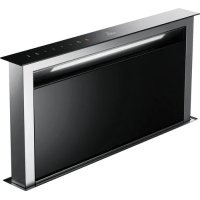
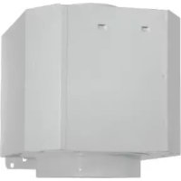
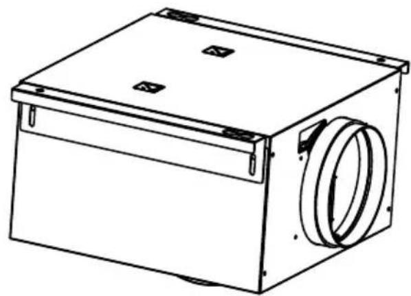
Cooker Hood
natural_image
Exterior view of a modern office building (no signage)
natural_image
Technical line drawing of a mechanical assembly with a cylindrical component mounted on a base plate (no text or symbols)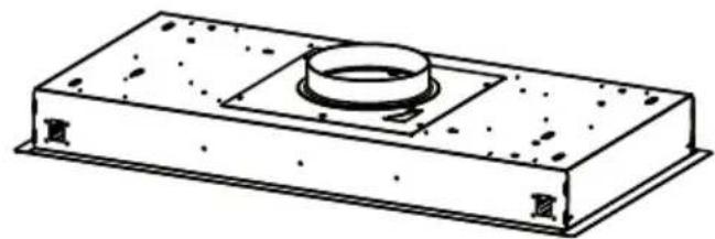
natural_image
Technical line drawing of a rectangular mechanical component with a central circular feature and flange (no text or symbols)Inspiration FX SM
Inspiration Slim FX
F SOMMAIRE
RACCORDEMENT ÉLECTRIQUE
CONSEILS D'INSTALLATIONS
POSE DE L'APPAREIL
FONCTIONNEMENT
CONSEILS D'UTILISATIONS
ENTRETIEN
GARANTIE ET SERVICE APRÈS-VENTE
REMARQUES
GB CONTENTS
ELECTRICAL WIRING
INSTALLATION ADVICE
FITTING THE APPLIANCE
OPERATION
USEFUL HINTS
MAINTENANCE
GUARANTEE AND AFTER-SALES-SERVICES
REMARKS
D INHALT
NETZANSCHLUSS
MONTAGEHILFEN
MONTAGE DES GERÄTES
BETRIEB DES GERÄTES
NUTZUNG
Thank you for buying a ROBLIN product which has been manufactured to the highest quality standards to meet your requirements.
We recommend you carefully read this booklet in which you will find instructions for installation, hints for use and maintenance.
The Instructions for Use apply to several versions of this appliance. Accordingly, you may find descriptions of individual features that do not apply to your specific appliance.
With this kit it is possible to place the blower of the kitchen hood to a remote position inside the house. Installation of the kit must be carried out by qualified staff, following all the rules given by the relevant authorities concerning the exhaust air ducting. The manufacturer will not be liable for any damages resulting from incorrect or from improper installation.
1 ELECTRICAL
- This cooker hood is fitted with a 3-core mains cable with a standard 10/16A earthed plug.
- Alternatively the hood can be connected to the mains supply via a double-pole switch having 3mm minimum contact gap on each pole.
- Before connecting to the mains supply ensure that the mains voltage corresponds to the voltage on the rating plate inside the cooker hood.
- Technical Specification: Voltage 220-240 V, single phase \~ 50 Hz / 220 V - 60Hz.
2 INSTALLATION ADVICE
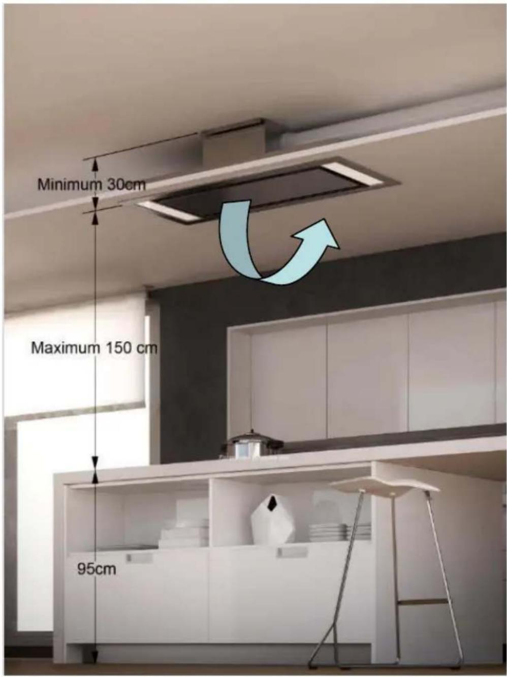
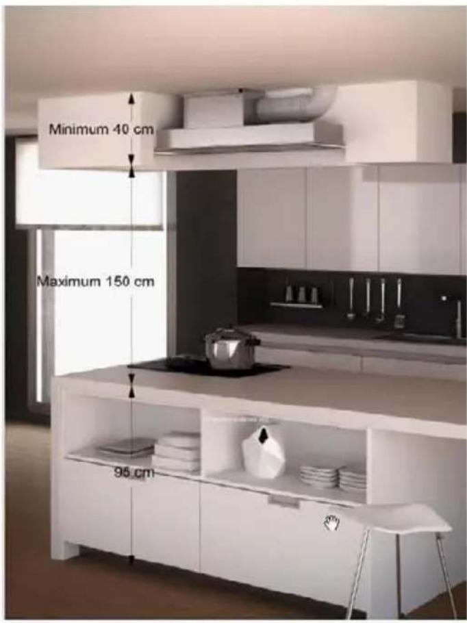
- Ensure the cooker hood is fitted in compliance with the recommended fixing heights: 150cm maximum.
- To ensure the safe operation of this cooker hood, we recommend that the hood should not be fitted below 65cm (for electric) or (70cm for gas) the measurements taken from the surface of the cooking appliance to the underside of the cooker hood.
- It is a possible fire risk if the hood is not sited as recommended.
- To ensure the best results, the cooking fumes should be able to rise naturally towards the inlet grilles on the underside of the cooker hood and the cooker hood should be positioned away from doors and windows, which will create turbulence.
- Ducting
- If the room where the hood is to be used contains a fuel-burning appliance such as a central heating boiler then its flue must be of the room sealed or balanced flue type.
- If other types of flue or appliances are fitted ensure that there is an adequate supply of fresh air to the room. Ensure the kitchen is fitted with an airbrick, which should have a cross-sectional measurement equivalent to the diameter of the ducting being fitted, if not larger.
- The ducting system for this cooker hood must not be connected to any existing ventilation system, which is being used for any other purposes or to a mechanically controlled ventilation ducting.
- The ducting used must be made from fire retardant materials and the correct diameter must be used, as incorrect sized ducting will affect the performance of this cooker hood.
- When the cooker hood is used in conjunction with other appliances supplied with energy other than electricity, the negative pressure in the room must not exceed 0.04 mbar to prevent the fumes from combustion being drawn back into the room.
- The appliance is for domestic use only and should not be operated by children or people who are infirm without supervision.
- This appliance must be positioned so that the wall socket is accessible.
- This appliance is not intended for use by persons (including children) with reduced physical, sensory or mental capabilities, or lack of experience and knowledge, unless they have been given supervision or instruction concerning use of the appliance by a person responsible for their safety.
Children should be supervised to ensure that they do not play with the appliance.
3 FITTING
Any permanent electrical installation must comply with the latest regulations concerning this type of installation and a qualified electrician must carry out the work. Non-compliance could cause serious accidents
or injury and would deem the manufacturers guarantee null and void.
IMPORTANT - The wires in this mains lead are coloured in accordance with the following code :
green / yellow : earth blue : neutral brown : live
As the colours of the wires in the mains lead of this appliance may not correspond with the coloured markings identifying the terminals in your plug, proceed as follows.
- The wire which is coloured green and yellow must be connected to the terminal in the plug which is marked with the letter E or by the earth symbol 12 or coloured green or green and yellow.
- The wire which is coloured blue must be connected to the terminal which is marked with the letter N or coloured black.
- The wire which is coloured brown must be connected to the terminal which is marked with the letter L or coloured red.
ATTENTION: Do not forget to use adequate plugs to the support brackets. Enquire after the manufacturers. Do an embedding if necessary. The manufacturer accepts no responsibility in case of a faulty hanging due to the drilling and the setting up of plugs in the ceiling.
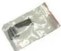
1) Unpack the hood parcel.
• FIXING BY THE STRUCTURE : LAYING OUT BEFORE FITTING THE HOOD
2) Mark the centre of the cooking appliance onto the ceiling with a plumb line. Draw the horizontal axes running parallel to the stove top onto the ceiling as illustrated Fig. 1.
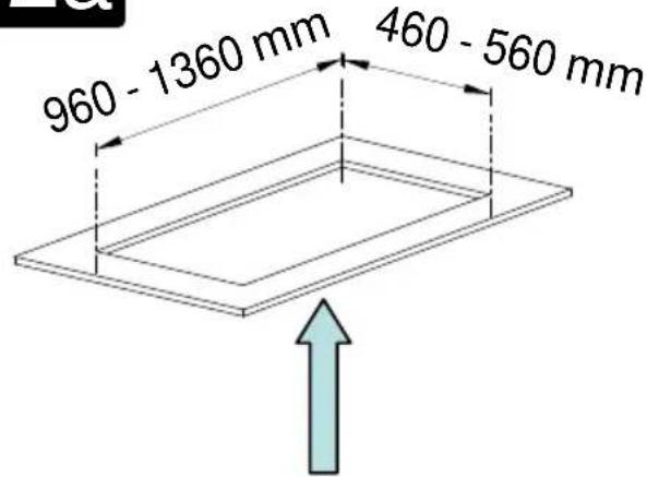
3) To carry out the cutting of embedding in the suspended ceiling (Fig 2a).
4) To mark the centers of different drillings to be carried out on the ceiling. (Fig 2b)
5) Drill the different holes with the appropriate masonry bit :
- The cut-out for the ducting ∅ 150 mm in the extraction
mode when ducting runs through the ceiling.
- The mains supply cords.
- The 4 fixing holes for ∅ 10 mm nuts and bolts.
When fixing the cooker hood to a plasterboard ceiling ensure it is reinforced as illustrated in Fig. 3 and attach using four ∅10mm nuts and bolts; ensuring the bolts as sleeved between the plasterboard and the joist supports to prevent the ceiling being damaged when the bolts are tightened up.
If the ceiling is concrete, use eight ∅ 10 mm steel rawl bolts. Plastic rawl plugs must not be used. Fit the motor housing (Fig. 4): 4 positions with 90°.
6) To adjust the height of the motor housing: 20 mm of adjustment (Fig. 5).
7) Open the deflector (Fig. 6 Rep. 12) by pushing / unlocking (Fig. 14).
8) To remove the metal filters.
- DUCTING
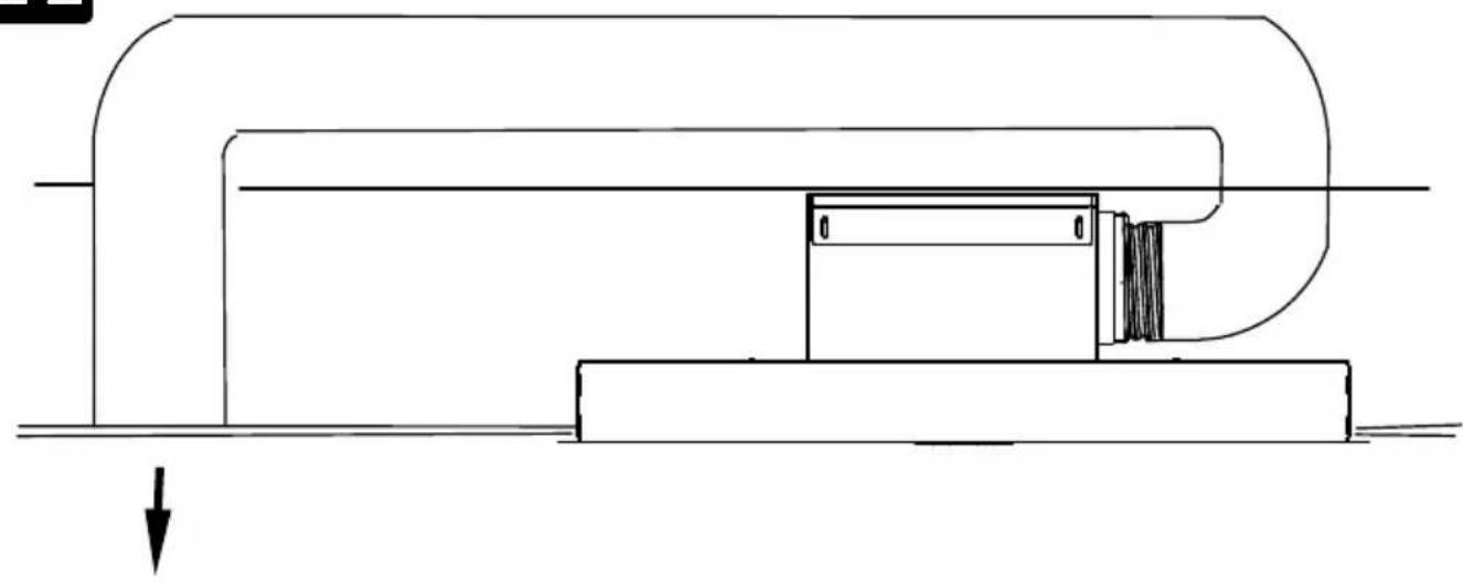
The hood is more effective when used in the extraction mode (ducted to the outside). When the cooker hood is ducted to the outside, charcoal filters are not required.
The ducting used must be 150 mm (6 INS), rigid circular pipe and must be manufactured from fire retardant material, produced to BS.476 or DIN 4102-B1. Wherever possible utilise rigid circular pipe which has a smooth interior, rather than the expanding concertina type ducting.
Maximum length of ducting run:
- 4 metres with 1 × 90^ bend.
- 3 metres with 2 x 90° bends.
- 2 metres with 3 × 90^ bends.
The above assumes our 150 mm (6 INS) ducting is being installed. Please note ducting components and ducting kits are optional accessories and have to be ordered, they are not automatically supplied with the chimney hood.
IN THE EXTRACTION MODE:
a- Fit the non-return backflow flaps C over the round outlet item 6 on top of the canopy while pressing down until they snap into position, and then connect the ducting 150mm (6 INS) and secure the connections with appropriate clamping rings or adhesive tape (Fig. 8).
b- Make the electrical connection of the motor as described in the section titled ELECTRICAL.
c- Place the canopy under the motor housing and fix it with the screws provided as illustrated in Fig. 10.
Attention: 2 persons are necessary to secure this operation..
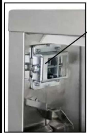
d- Connect the electrical plug of the motor cord on the body hood (Fig.7).
e- Check the connectors of the motor (Fig 9).
f- Test the lights and the fan motor.
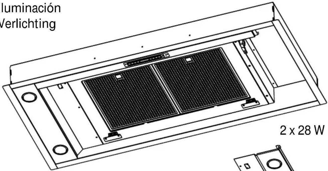
g- Fit the metal grease filters and close the deflector.
IN THE RECIRCULATION MODE:
a- To carry out an inlet for recycling air in the kitchen (Fig.11).
b- Connect the ducting 150mm (6 INS) not provided between motors item 6 and the recirculation spigot and secure the connections with appropriate clamping rings or adhesive tape (Fig. 12).
c- Make the electrical connection of the motor as described in the section titled ELECTRICAL.
d- Place the canopy under the motor housing and fix it with the crews provided as illustrated in Fig. 10.
Attention: 2 persons are necessary to secure this operation.
e- Connect the electrical plug of the motor cord on the body hood (Fig.7).
f- Check the connectors of the motor (Fig 9).
g- Test the lights and the fan motor.
h- Fit the charcoal filter onto the inlets of the motor (Fig. 13).
i- Fit the metal grease filters and close the deflector.
• CLIPPAGE ON THE FALSE CEILING
2) Mark the centre of the cooking appliance onto the ceiling with a plumb line. Draw the horizontal axes running parallel to the stove top onto the ceiling as illustrated Fig. 1.
3) To carry out the cutting of embedding in the suspended ceiling (Fig 2a).
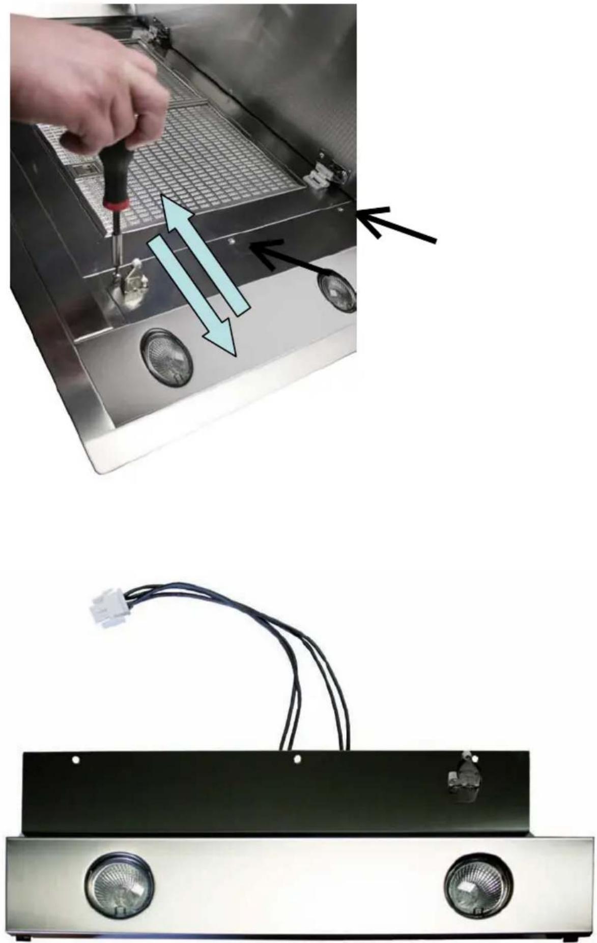
4) To remove the lighting front panel (Fig. 15).
5) To unscrew the screws of the clips according to the thickness of the false ceiling (Fig. 16). When fixing the cooker hood to a plasterboard ceiling ensure it is reinforced as illustrated in Fig. 17. For the false ceiling in MDF of 18 mm, 4 holds of compensation (2 mm thickness) are provided with the hood.
6) Open the deflector (Fig. 6 Rep. 12) by pushing / unlocking (Fig. 14).
7) To remove the metal filters.
IN THE EXTRACTION MODE:
a- Fit the non-return backflow flaps C over the round outlet item 6 on top of the canopy while pressing down until they snap into position, and then connect the ducting 150mm (6 INS) and secure the connections with appropriate clamping rings or adhesive tape (Fig. 8).
b- Make the electrical connection of the motor as described in the section titled ELECTRICAL.
c- Place the canopy under the motor housing and fix it with the screws provided as illustrated in Fig. 10 or clip the hood on the false ceiling (Fig. 15), to tighten the screws (Fig. 16) and to fit back the lighting front panel.
Attention: 2 persons are necessary to secure this operation..
d- Connect the electrical plug of the motor cord on the body hood (Fig.7).
e- Check the connectors of the motor (Fig 9).
f- Test the lights and the fan motor.
g- Fit the metal grease filters and close the deflector.
IN THE RECIRCULATION MODE:
a- To carry out an inlet for recycling air in the kitchen (Fig.11).
b- Connect the ducting 150mm (6 INS) not provided between motors item 6 and the recirculation spigot and secure the connections with appropriate clamping rings or adhesive tape (Fig. 12).
c- Make the electrical connection of the motor as described in the section titled ELECTRICAL.
d- Place the canopy under the motor housing and fix it with the screws provided as illustrated in Fig. 10 or clip the hood on the false ceiling (Fig. 15), to tighten the screws (Fig. 16) and to fit back the lighting front panel.
Attention: 2 persons are necessary to secure this operation.
e- Connect the electrical plug of the motor cord on the body hood (Fig.7).
f- Check the connectors of the motor (Fig 9).
g- Test the lights and the fan motor.
h- Fit the charcoal filter onto the inlets of the motor (Fig. 13).
i- Fit the metal grease filters and close the deflector.
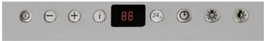
4 OPERATION
text_image
88 24A B C D E F G H
Cont rol pane I
| Button Function Display | ||
| A | Turns the suction motor on and off a t the last speed used. | Displays the speed set |
| B Decrease the working speed. | ||
| C Increase the working speed. | ||
| D | Activates inte nsive speed from any other speed even with the motor off. This speed is timed to run for 10 minutes, after which the system returns to the previous speed. Suitable to deal with maximum cooking fumes. | Displays H1 and the bottom right hand spot flashes once a second.the |
| E | Activates the motor at a speed that allows extraction of 100 m^3/h for 10 minutes every hour, after which the motor stops.When the filter alarm is on , press t he button for approximately 3 seconds to reset t alarm. T these indications are only visible when the motor is turned off. | Displays 24 and the bottom right hand spot flashes, while the motor is turned onOn completing the procedure the previous indicator is turned off:FF indicates th at the metal grease filter need washing. The alarm is triggered after the Hood has been in operation for 100 hours.EF indicates th at the activated c harcoal filter needs changing and the metal grease filters need washing. The alarm is triggered after the Hood has been in operation for 200 hours. |
| F | Activates automatic shutdown after 30'. Suitable to complete elimination of residual odours. Can be activated from any position, and is turned off by pressing the button or switching the motor off. | Alternately displays the working speed and the time remaining before the hood turns off. The bottom right hand spot flashes. |
| G | Turns the main lighting system on and off. | |
| H | Turns the ambiance lighting system on and off. | |
5 USEFUL HINTS
• To obtain the best performance we recommend you to switch 'ON' the cooker hood a few minutes (in the boost setting) before you start cooking and you should leave it running for approximately 15 minutes after finishing.
• IMPORTANT: NEVER DO FLAMBÉ COOKING UNDER THIS COOKER HOOD
- Do not leave frying pans unattended during use as over-heated fat and oil might catch fire.
- Do not leave naked flames under this cooker hood.
- Switch 'OFF' the electric and gas before removing pots and pans.
- Ensure heating areas on your hotplate are covered with pots and pans when using the hotplate and cooker hood simultaneously.
6 MAINTENANCE
Before carrying out any maintenance or cleaning isolate the cooker hood from the mains supply. The cooker hood must be kept clean; a build up of fat or grease may cause a fire hazard.
Casing
- Wipe the cooker hood frequently with a clean cloth, which has been immersed in warm water containing a mild detergent and wrung out.
- Never use excessive amounts of water when cleaning particularly around the control panel.
- Never use scouring pads or abrasive cleaners.
• Always wear protective gloves when cleaning the cooker hood.
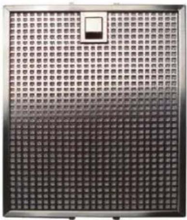
Metal Grease Filters : The metal grease filters absorb grease and dust during cooking in order to keep clean the cooker hood inside. The grease filters should be cleaned once a month or more frequently if the hood is used for more than 3 hours per day.
To remove and replace the metal grease filters
- Remove the metal grease filters one at a time by releasing the catches on the filters; the filters can now be removed.
- The metal grease filters should be washed, by hand, in mild soapy water or in a dishwasher.
- Allow to dry before replacing.
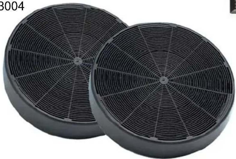
Active Charcoal Filter : The charcoal filter cannot be cleaned. The filter should be replaced at least every three months or more frequently if the hood is used for more than three hours per day.
To remove and replace the filter
- Remove the metal grease filters.
- Press against the two retaining clips, which hold the charcoal filter in place and this will allow the filter to drop down and be removed.
- Clean the surrounding area and metal grease filters as directed above.
- Insert the replacement filter and ensure the two retaining clips are correctly located.
- Replace the metal grease filters.
Extraction tube : Check every 6 months that the dirty air is being extracted correctly. Comply with local rules and regulations with regard to the extraction of ventilated air.
Lighting : If the lamp fails to function check to ensure it is fitted correctly into the holder. If lamp failure has occurred then it should be replaced with identical replacement.
Do not replace with any other type of lamp and do not fit a lamp with a higher rating.
Remote control handset : Caution, the remote control handset must be fitted with standard LR03-AAA size 1.5V zinc-carbon alkaline batteries. These batteries should give a long life and constant discharge throughout their life. These batteries must be disposed of properly and could explode if damaged or exposed to heat. Do not dispose of on fire. Dispose of batteries in the appropriate sort
7 GUARANTEE AND AFTER SALES SERVICE
- In the event of any malfunction or anomaly, notify your fitter who will have to check the appliance and its connection.
- In the event of damage to the mains supply cable, this can only be replaced by at approved repair centre appointed by the manufacturer who will have the required tools and equipment to carry out any repairs properly. Repairs carried out by other persons will invalidate the guarantee.
- Use only genuine spare parts. Should these warnings fail to be observed it could affect the safety of your cooker hood.
- When ordering spare parts quote the model number and serial number written on the rating plate, which is found on the casing behind the grease filters inside the hood.
• Proof of purchase will be required when requesting service. Therefore, please have your receipt available when requesting service as this constitutes the date from which your guarantee commenced.
This Guarantee does not cover :
- Damage or calls resulting from transportation, improper use or neglect, the replacement of any light bulbs or filters or removable parts of glass or plastic.
These items are considered to be consumable under the terms of this guarantee.
8 REMARKS
This appliance complies with European regulations on low voltages Directive 2006/95/CE on electrical safety, and with the following European regulations: Directive 2004/108/CE on electromagnetic compatibility and Directive 93/68 on EC marking.
When this crossed-out wheeled bin symbol ↗ is attached to a product it means the product is covered by the European directive 2002/96/EC. Your product is designed and manufactured with high quality materials and components, which can be recycled and reused. Please inform yourself about the local separate collection system for electrical and electronic product. Please act according to your local rules and do not dispose of your old products with your normal household waste. The correct disposal of your old product will help prevent potential negative consequences for the environment and human health.
3 INSTALLATIE VAN HET APPARAAT
natural_image
Simple line drawing of a wind turbine with three blades and a central hub, mounted on a rectangular base (no text or symbols)2a
text_image
960 - 1360 mm 460 - 560 mm
natural_image
Technical line drawing of a mechanical assembly with a cylindrical component mounted on a rectangular base (no text or symbols)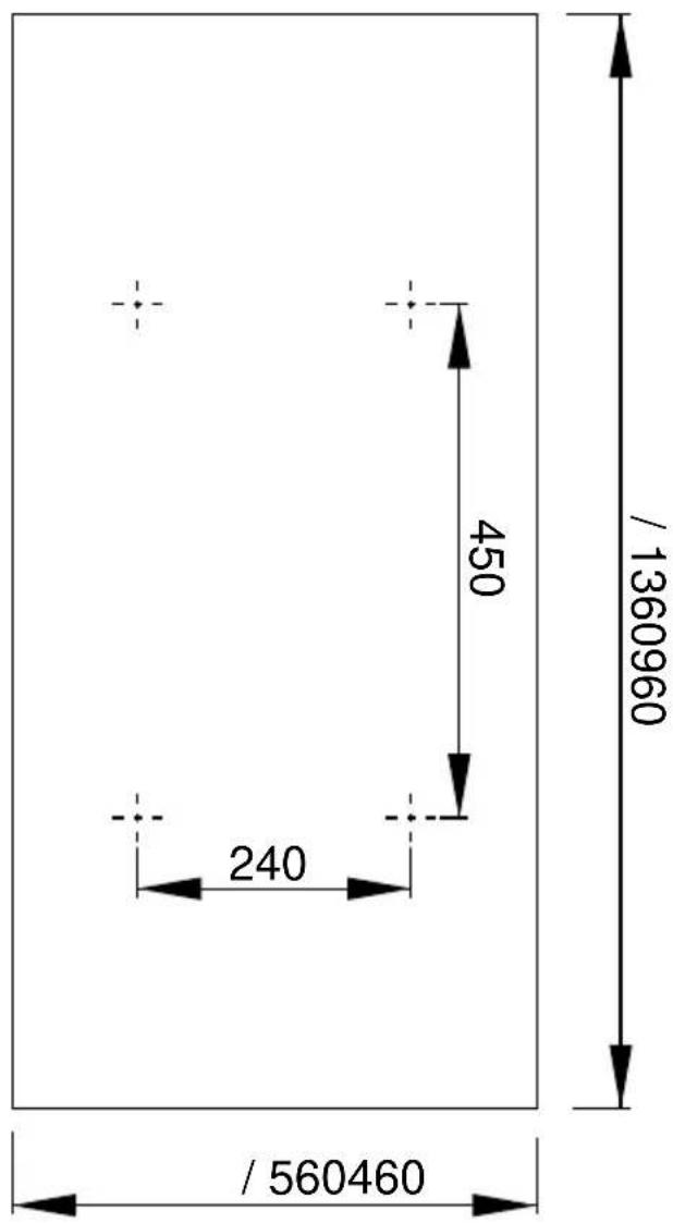
text_image
450 240 / 1360960 / 5604602b
3
natural_image
Technical line drawing of a mechanical housing component with mounting brackets and central hole (no text or symbols)4
text_image
270 90° 371.5 180° 0° 270° 36 3425
text_image
20 299 +20 100 / 14001000
natural_image
Technical line drawing of a mechanical housing with airflow arrows indicating direction (no text or symbols)
20 mm
6
text_image
6 127
natural_image
Technical line drawing of a mechanical component with an arrow indicating assembly or connection (no text or symbols present)8
text_image
6 C Ø 150
text_image
270 90° 371.5 180° 0° 270° 36 3429
natural_image
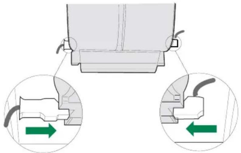
Mechanical assembly diagram showing two views of a component with green directional arrows indicating movement or force (no text or symbols present)10
natural_image
Technical line drawing of a rectangular industrial housing with a circular vent and mounting flanges (no text or symbols)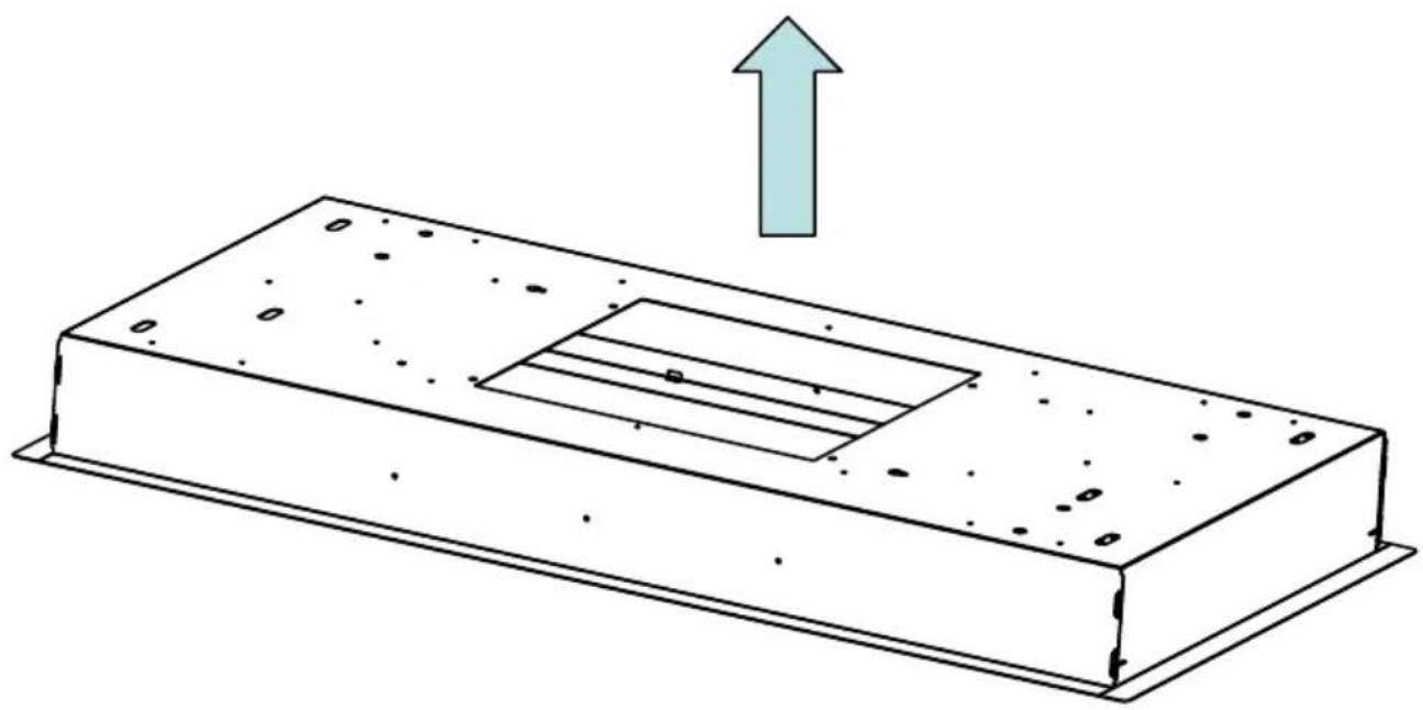
natural_image
Diagram of a rectangular electronic component with internal slots and mounting holes, featuring an upward arrow indicating force or direction (no text or symbols present)11
natural_image
Technical line drawing of a mechanical assembly with no visible text or symbols12
text_image
Ø 150 ⑥13
ACCESSOIRES
ACCESSORIES
ZUBEHÖRE
ACCESSORI
ACCESORI
ACCESSOIRES
13MC075
253 × 300 × 9 mm
x 2 (1000)
× 3 (1400)
text_image
SYLVANIA HI-SPOT® ES56 230V 28 2 230V
natural_image
Close-up of a conical incandescent light bulb (no visible text or symbols)4 × 28 ~W
12EC024
text_image
Scanned image of a grid-based electronic component or circuit board with Chinese labels and a small black square icon.5403004
natural_image
Two black circular filter fans with radial blades, no text or symbols visible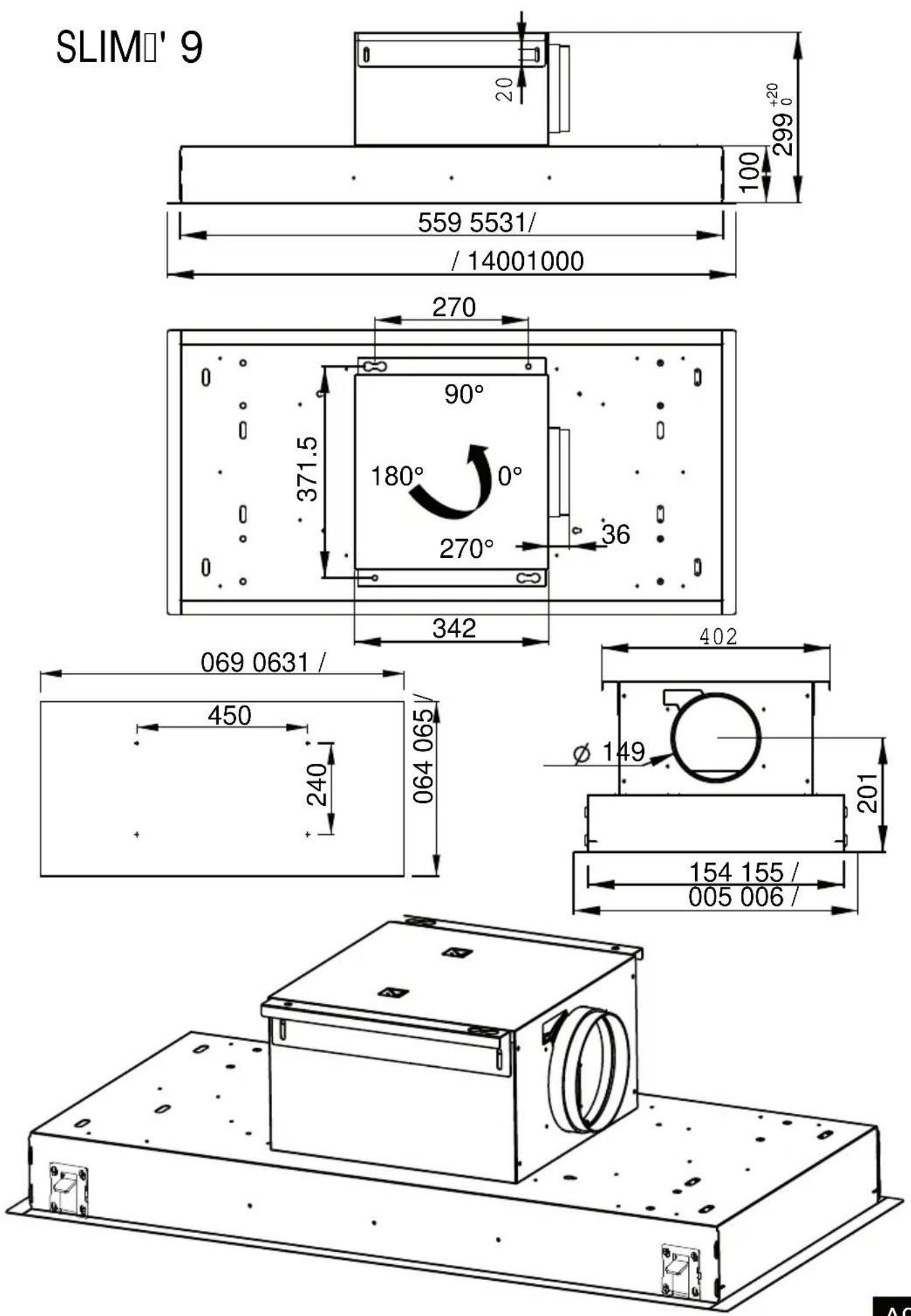
text_image
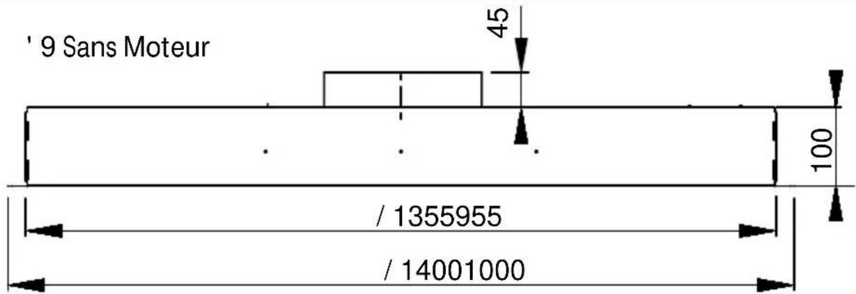
' 9 Sans Moteur 45 100 / 1355955 / 14001000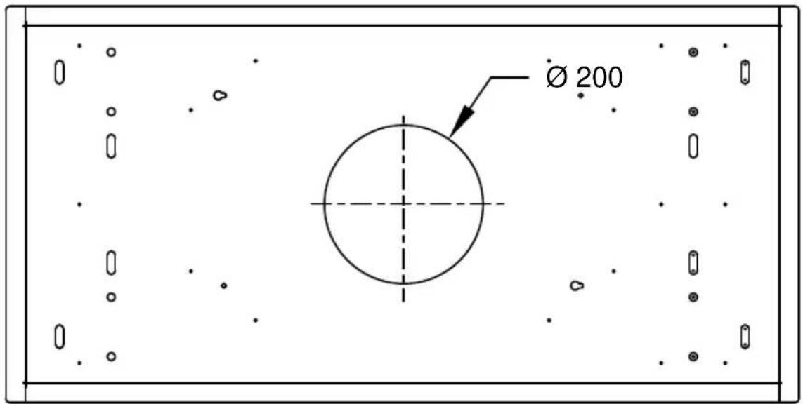
text_image
Ø 200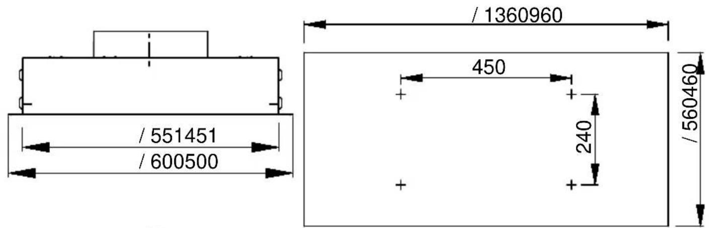
text_image
/ 1360960 / 551451 / 600500 450 240 / 560460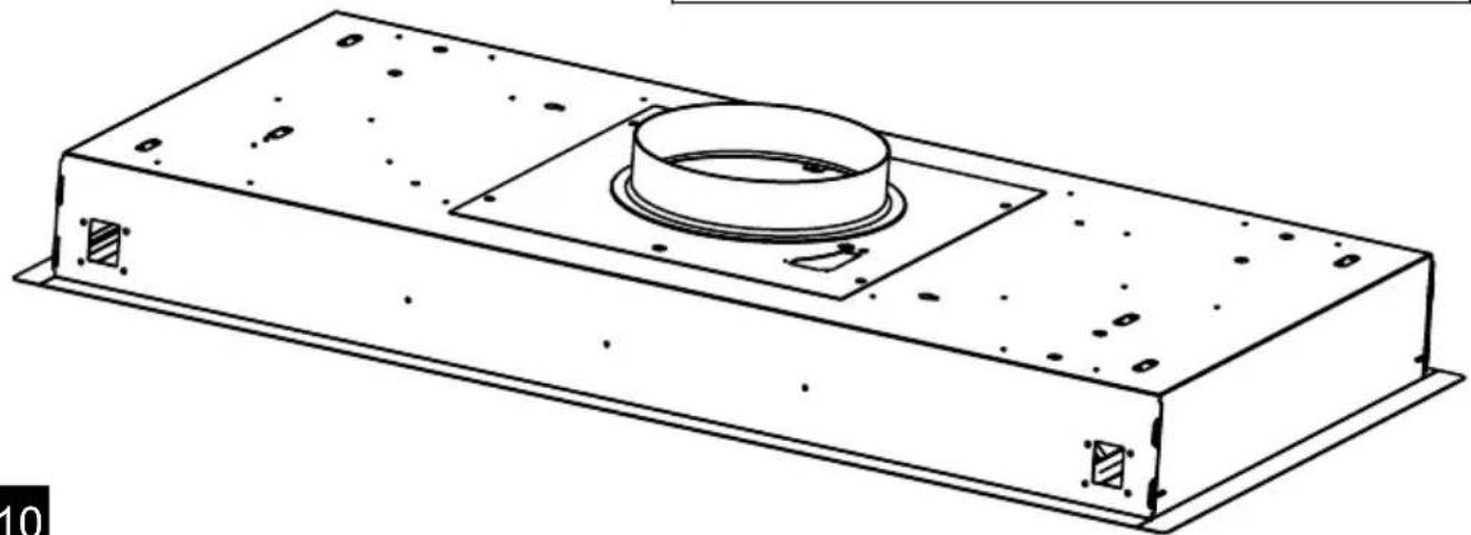
natural_image
Technical line drawing of a rectangular mechanical component with a central cylindrical feature and mounting flanges (no text or symbols)Eclairage
Lighting
Beleuchtung
Illumiazione
Iluminación
Verlichting
natural_image
Pure technical diagram of a mechanical component with arrows indicating direction (no text or symbols)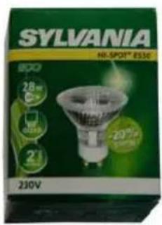
text_image
SYLVANIA HI-SPOT® ESSE 800 28 650 21 230V 2000V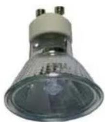
natural_image
Close-up of a small incandescent light bulb with three metallic pins (no visible text or symbols)4 × 28 ~W
12EC024
text_image
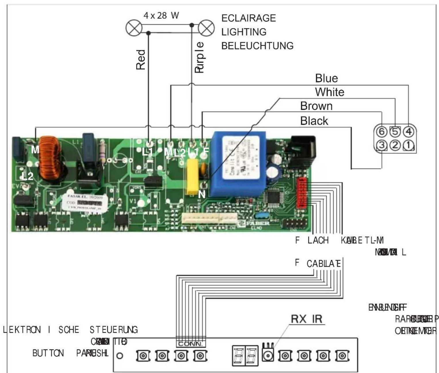
4 x 28 W ECLAIRAGE LIGHTING BELEUCHTUNG Red Purple Blue White Brown Black M L1 M L2 L1 F N F LACH KABETL-M ML L2 F CABILATE ENBANGFF LEKTRON I SCHE STEUERUNG RX IR RARBURGEBP OBTMEMBER BUTTON PARIBSHL CONN. 6 5 4 3 2 1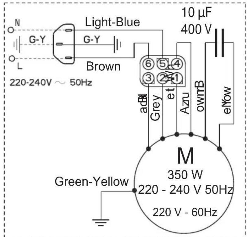
text_image
Light-Blue G-Y G-Y Brown 220-240V ~ 50Hz 10 µF 400 V ad BI Grey et Azu ownB eNow M 350 W 220 - 240 V 50Hz 220 V - 60Hz Green-YellowA - AZUR - AZUR - AZUR BLAU
BK - BLACK - NOIR- SCHWARZ
B - BLUE - BLEU - BLAU
Br - BROWN - BRUN - BRAUN
G-Y - GREEN YELLOW - VERT JAUNE - GRÜN GELB
Gr - GREY - GRIS - GRAU
L B - LIGHT BLUE - BLEU CLAIR - HELL BLAU
P - PINK - ROSE - ROSA
V - PURPLE - MAUVE - MALVER FARBIG
R - RED - ROUGE - ROT
W - WHITE - BLANC - WEISS
W-P - WHITE PINK - BLANC ROSE - WEISS ROSA
Y - YELLOW - JAUNE - GELB
Roblin
MAJ (UPDATE):10/12/22
UK ELECTRICAL CONNECTION ELECTRICAL REQUIREMENTS
Any permanent electrical installation must comply with the latest I.E.E. Regulations and local Electricity Board regulations. For your own safety this should be undertaken by a qualified electrician e.g. your local Electricity Board, or a contractor who is on the roll of the National Inspection Council for Electrical Installation Contracting (NICEIC).
ELECTRICAL CONNECTION
Before connecting to the mains supply ensure that the mains voltage corresponds to the voltage on the rating plate inside the cooker hood.
This appliance is fitted with a 2 core mains cable and must be permanently connected to the electricity supply. The wire which is coloured blue must be connected via a double-pole switch having 3mm minimum contact gap on each pole. A Switched Fuse Connection Unit
to BS.1363 Part 4, fitted with a 3 Amp fuse, is a recommended mains supply connection accessory to the terminal which is marked with the letter 'L' or ensure compliance with the Safety Requirements coloured red.
applicable to fixed wing instructions.
text_image
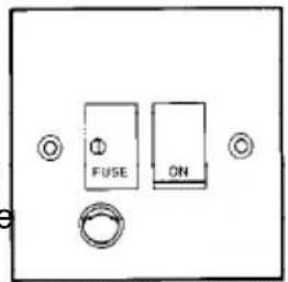
FUSE ON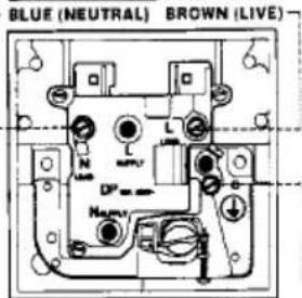
text_image
BLUE (NEUTRAL) BROWN (LIVE)GREEN & YELLOW (EARTH)
The wires in this mains lead are coloured in accordance with the following code:
Green & Yellow Earth Blue Neutral Brown Live
As the colours of the wires in the mains lead of this appliance may not correspond with the coloured markings identifying the terminals in your connection unit, proceed as follows:-
CH
The wire which is coloured blue must be connected to the terminal which is marked with the letter 'N' or coloured black.
The wire which is coloured brown must be connected to the terminal which is marked with the letter 'L' or coloured red.
SEV 1011, SN416534-2, CH-Typ 12
text_image
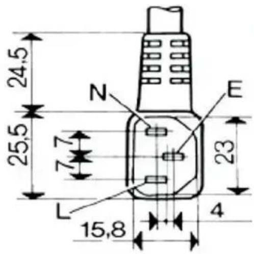
24,5 25,5 7 N E 23 L 15,8 4
natural_image
Coiled black electrical plug with terminal connectors (no text or symbols visible)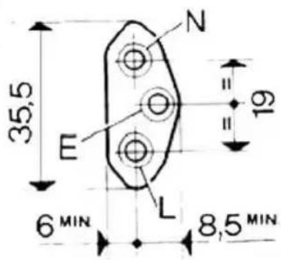
text_image
35,5 E N = 19 6 MIN L 8,5 MIN
text_image
Composants Components Bauelemente Componenti Componentes Onderdelen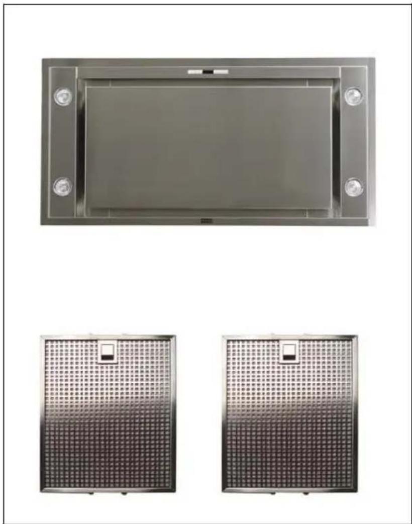
natural_image
Two metallic rectangular panels with grid patterns, each mounted on a flat surface with mounting holes (no text or symbols visible)
(2 mm)
text_image
Illustration of a stack of documents with visible text lines, likely indicating a list or document section.
INSPIRATION SLIM FX
Rating plate of the cookerhood
Adjustment tightening hinge
text_image
Close-up of a hand adjusting a metal component with a large gender symbol and directional arrow overlay14
text_image
Minimum 30cm Maximum 150 cm 95cm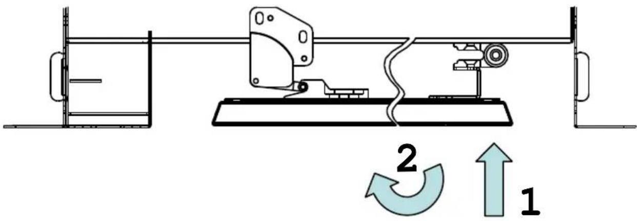
text_image
Technical diagram of a mechanical assembly with labeled components and directional arrows indicating motion or flow.15
16
natural_image
Close-up of a mechanical device with a black arrow pointing to a component (no visible text or symbols)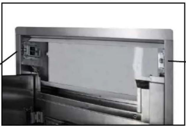
natural_image
Interior view of a stainless steel industrial machine with visible internal components and mounting brackets (no text or symbols)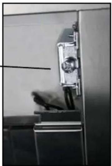
natural_image
Interior view of a double door with a metal door clamped and a small object on the side (no visible text or symbols)17
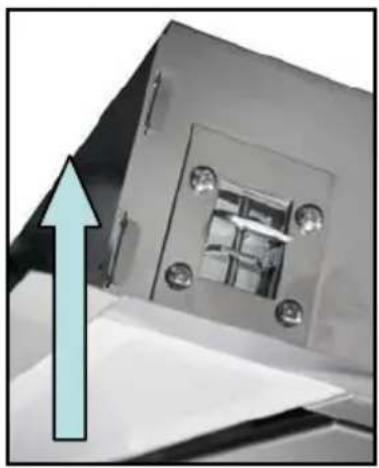
natural_image
Close-up of a metallic mechanical component with a blue upward arrow indicating direction (no text or symbols visible)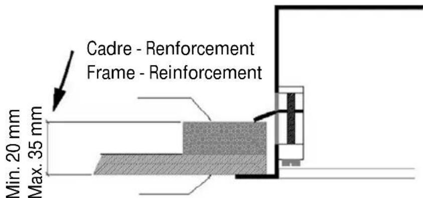
text_image
Cadre - Reinforcement Frame - Reinforcement Min. 20 mm Max. 35 mmFaux - plafond (platre) False ceiling (plaster)
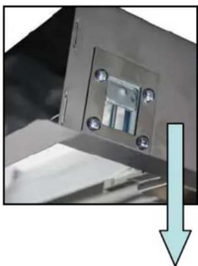
natural_image
Close-up of a metallic mechanical component with mounting holes and a downward arrow indicating compression (no text or symbols visible)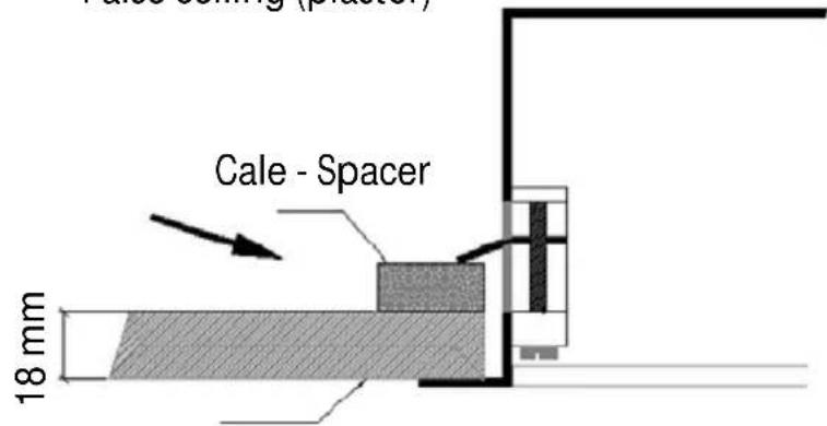
text_image
Cale - Spacer 18 mmFaux - plafond (MDF) False ceiling (MDF)
text_image
Minimum 40 cm Maximum 150 cm 95 cm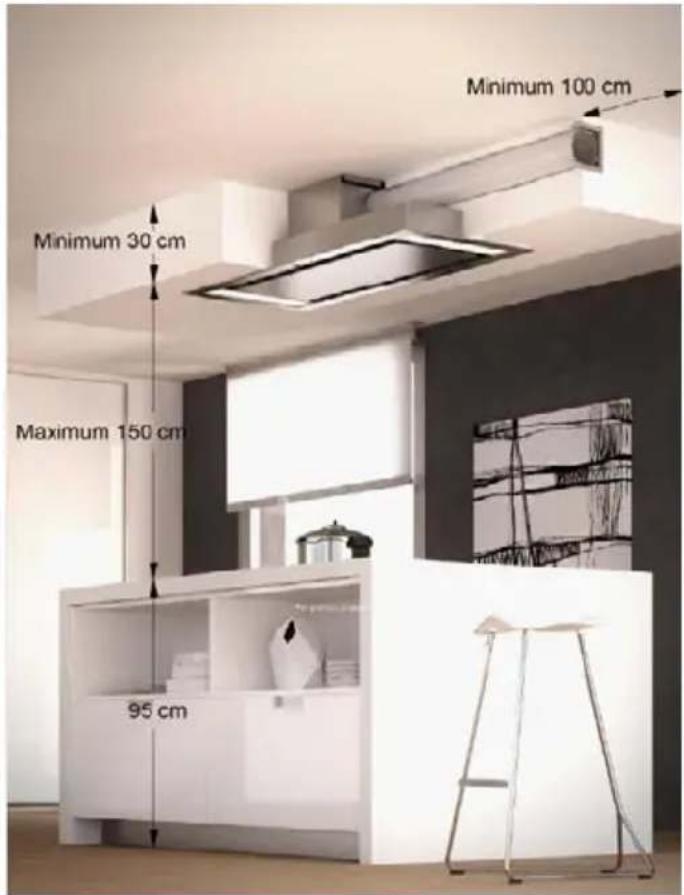
text_image
Minimum 100 cm Minimum 30 cm Maximum 150 cm 95 cm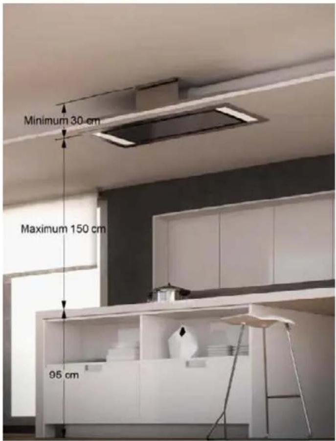
text_image
Minimum 30 cm Maximum 150 cm 95 cm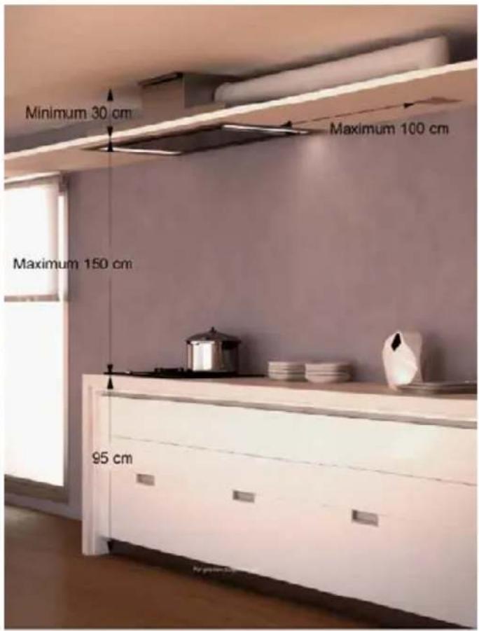
text_image
Minimum 30 cm Maximum 100 cm Maximum 150 cm 95 cmRoblin
FRANKE France S.A.S.