
Elina - Basket ROBLIN - Free user manual and instructions
Find the device manual for free Elina ROBLIN in PDF.

| Product type | Built-in range hood |
| Brand | Roblin |
| Model | Elina |
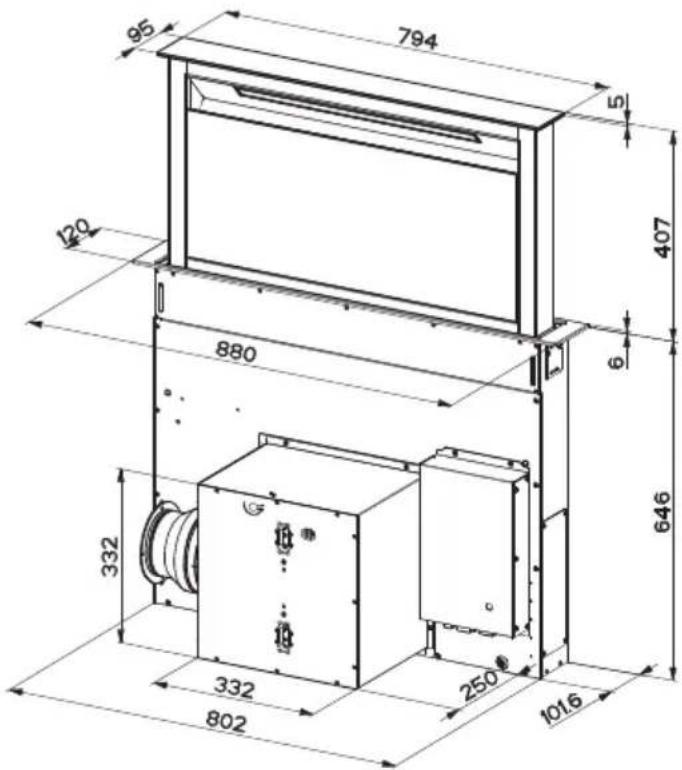
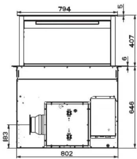
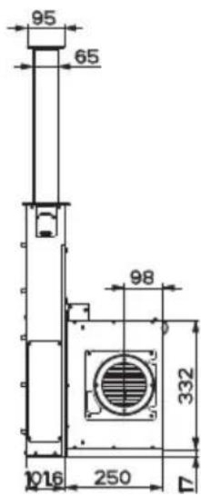
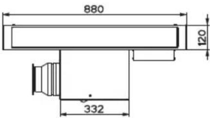
| Dimensions (W x D x H) | 880 x 332 x 332 mm |
| Estimated weight | 15 kg |
| Electrical supply | 220-240 V ~ 50/60 Hz |
| Number of speeds | 4 + intensive speed |
| Functions | LED lighting, delayed shutdown (Delay 30 min), optional remote control |
| Control type | Touch panel with buttons and remote control (on request) |
| Grease filters | Metallic, dishwasher safe (every 2 months) |
| Activated charcoal filter | Replace every 4 months (recirculation version), washable up to 5 times |
| Maintenance | Clean with a damp cloth and mild detergent. Do not use abrasive products. |
| Minimum safety distance | 650 mm between hob and hood |
| Commercial warranty | 2 years parts (excluding labor and travel) |
| Availability of spare parts | 10 years from date of purchase |
| Installation version | Ducted (external exhaust) or recirculating (filtration) |
| Air outlet diameter | 150 mm (reducible to 120 mm) |
| Installation | Built into kitchen cabinet, top or bottom passage |
| Gas hob compatibility | Max power 12.4 kW (5 burners) |
Frequently Asked Questions - Elina ROBLIN
User questions about Elina ROBLIN
0 question about this device. Answer the ones you know or ask your own.
Ask a new question about this device
Download the instructions for your Basket in PDF format for free! Find your manual Elina - ROBLIN and take your electronic device back in hand. On this page are published all the documents necessary for the use of your device. Elina by ROBLIN.
USER MANUAL Elina ROBLIN
natural_image
Technical line drawing of a mechanical or electrical enclosure assembly (no text or symbols)SOMMAIRE
FR
CONSEILS ET SUGGESTIONS.... 3
CARACTERISTIQUES....6
INSTALLATION 8
UTILISATION 18
ENTRETIEN....20
INDEX
EN
RECOMMENDATIONS AND SUGGESTIONS 23
CHARACTERISTICS 26
INSTALLATION....28
USE 38
MAINTENANCE 40
INHALTSVERZEICHNIS
DE
natural_image
Illustration of a chemical experiment setup with a conical funnel, thermometer, and smokestack (no text or symbols)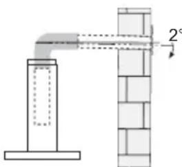
natural_image
Technical diagram showing a pipe connection with a 2° angle indicator (no text or symbols present)natural_image
Illustration of a greenhouse with a container and two plants, crossed by a green X (no text or symbols)natural_image
Illustration of a hand holding a screwdriver, a tool, and a small mechanical component (no text or symbols)natural_image
Technical line drawing of a mechanical assembly with two components, no visible text or symbols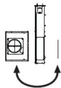
natural_image
Pure mechanical component diagram showing a square plate with a circular cross symbol and a vertical cylindrical shaft, no text or labels present.natural_image
Technical line drawing of a mechanical assembly with two components, one rectangular and one rectangular, showing internal components (no text or symbols)natural_image
Pure mechanical diagram showing a square component with a crosshair and a vertical shaft, connected by curved arrows (no text or symbols)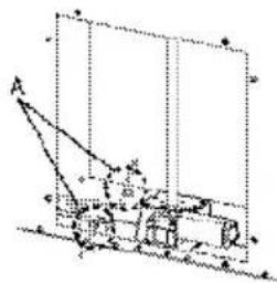
natural_image
Technical line drawing of a mechanical or electrical enclosure with labeled component '12c' (no readable text or symbols beyond label)natural_image
Pure mechanical diagram showing a vertical shaft connected to two circular components with crosshairs, no text or symbols present.2


natural_image
Technical line drawing of a mechanical assembly with a magnified inset showing internal components (no text or symbols)
natural_image
Technical line drawing of a mechanical assembly with no visible text or symbolsnatural_image
Technical line drawing of a mechanical assembly with no visible text or symbolsnatural_image
Pure technical line drawing of a rectangular beam with supports and hidden edges (no text or symbols)natural_image
Technical line drawing of a mechanical setup with a handle and frame (no text or symbols)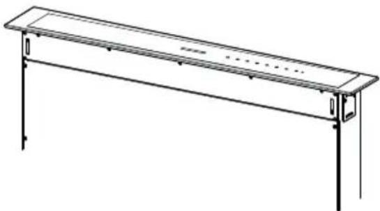
natural_image
Line drawing of a long rectangular table with a flat top and two vertical supports at both ends (no text or symbols)natural_image
Line drawing of a hand holding a rectangular shelf with horizontal bands, mounted on a metal frame (no text or symbols)
natural_image
Illustration of a car with a circular head and internal components, showing a green arrow pointing to the bottom-right corner (no text or symbols)natural_image
Diagram of a hand holding a rectangular object with arrows indicating rotation or movement (no text or symbols)natural_image
Hand holding a smartphone with a green arrow indicating left touch (no text or symbols)- Retirer le comfort panel.
natural_image
Diagram showing three steps of a device being folded or placed, with no visible text or symbols.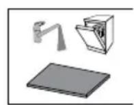
Éclairage
The Instructions for Use apply to several versions of this appliance. Accordingly, you may find descriptions of individual features that do not apply to your specific appliance.
INSTALLATION
- The manufacturer will not be held liable for any damages resulting from incorrect or improper installation.
- The minimum safety distance between the cooker top and the extractor hood is 650 mm (some models can be installed at a lower height, please refer to the paragraphs on working dimensions and installation).
- Check that the mains voltage corresponds to that indicated on the rating plate fixed to the inside of the hood.
- For Class I appliances, check that the domestic power supply guarantees adequate earthing.
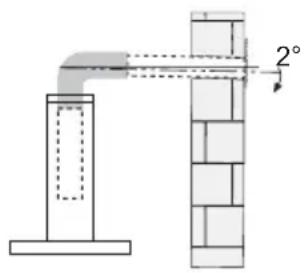
Connect the extractor to the exhaust flue through a pipe of minimum diameter 120 mm. The route of the flue must be as short as possible.
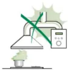
- Do not connect the extractor hood to exhaust ducts carrying combustion fumes (boilers, fireplaces, etc.).
- If the extractor is used in conjunction with non-electrical appliances (e.g. gas burning appliances), a sufficient degree of aeration must be guaranteed in the room in order to prevent the backflow of exhaust gas. The kitchen must have an opening communicating directly
with the open air in order to guarantee the entry of clean air. When the cooker hood is used in conjunction with appliances supplied with energy other than electric, the negative pressure in the room must not exceed 0,04 mbar to prevent fumes being drawn back into the room by the cooker hood.
- The air must not be discharged into a flue that is used for exhausting fumes from appliances burning gas or other fuels (not applicable to appliances that only discharge the air back into the room).
- In the event of damage to the power cable, it must be replaced by the manufacturer or by the technical service department, in order to prevent any risks.
natural_image
Illustration of a chemical experiment setup with a conical flask, thermometer, and smokestack (no text or symbols)- If the instructions for installation for the gas hob specify a greater distance specified above, this has to be taken into account. Regulations concerning the discharge of air have to be fulfilled.
- Use only screws and small parts in support of the hood.
Warning: Failure to install the screws or fixing device in accordance with these instructions may result in electrical hazards.
- Connect the hood to the mains through a two-pole switch having a contact gap of at least 3 mm.
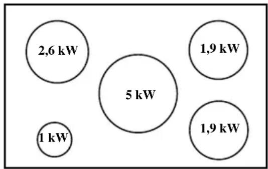
- This Cooker hood can be used in conjunction with a Gas Cook Top having the following characteristics:
• Maximum power 12,4 kW - 5 fire like the picture
bubble
| Bubble Size (kW) | Color | | :--- | :--- | | 2,6 | Dark Blue | | 5 | Medium Dark Blue | | 1,9 | Light Blue | | 1 | Dark Red | | 1,9 | Light Blue |USE
- The extractor hood has been designed exclusively for domestic use to eliminate kitchen smells.
- Never use the hood for purposes other than for which it has been designed.
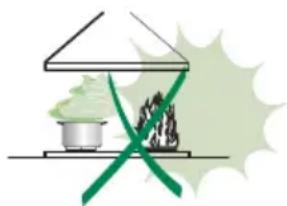
- Never leave high naked flames under the hood when it is in operation.
- Adjust the flame intensity to direct it onto the bottom of the pan only, making sure that it does not engulf the sides.
- Deep fat fryers must be continuously monitored during use: overheated oil can burst into flames.
- Do not flambè under the range hood; risk of fire.
- This appliance can be used by children aged from 8 years and above and persons with reduced physical,
sensory or mental capabilities or lack of experience and knowledge if they have been given supervision or instruction concerning use of the appliance in a safe way and understand the hazards involved. Children shall not play with the appliance. Cleaning and user maintenance shall not be made by children without supervision.
- This appliance is not intended for use by persons (including children) with reduced physical, sensory or mental capabilities, or lack of experience and knowledge, unless they have been given supervision or instruction concerning use of the appliance by a person responsible for their safety.
natural_image
Illustration of a food stall with green vegetables and a crossed green ribbon, set against a light green background (no text or symbols)- “CAUTION: Accessible parts may become hot when used with cooking appliances.”
MAINTENANCE
- Switch off or unplug the appliance from the mains supply before carrying out any maintenance work.
- Clean and/or replace the Filters after the specified time period (Fire hazard).
- The Grease filters must be cleaned every 2 months of operation, or more frequently for particularly heavy usage, and can be washed in a dishwasher.
- The Activated charcoal filter is not washable and cannot be regenerated, and must be replaced approximately every 4 months of operation, or more frequently for particularly heavy usage.
- "Failure to carry out cleaning as indicated will result in a fire hazard".
- Clean the hood using a damp cloth and a neutral liquid detergent.
The symbol on the product or on its packaging indicates that this product may not be treated as household waste. Instead it shall be handed over to the applicable collection point for the recycling of electrical and electronic equipment. By ensuring this product is disposed of correctly, you will help prevent potential negative consequences for the environment and human health, which could otherwise be caused by inappropriate waste handling of this product. For more detailed information about recycling of this product, please contact your local city office, your household waste disposal service or the shop where you purchased the product.
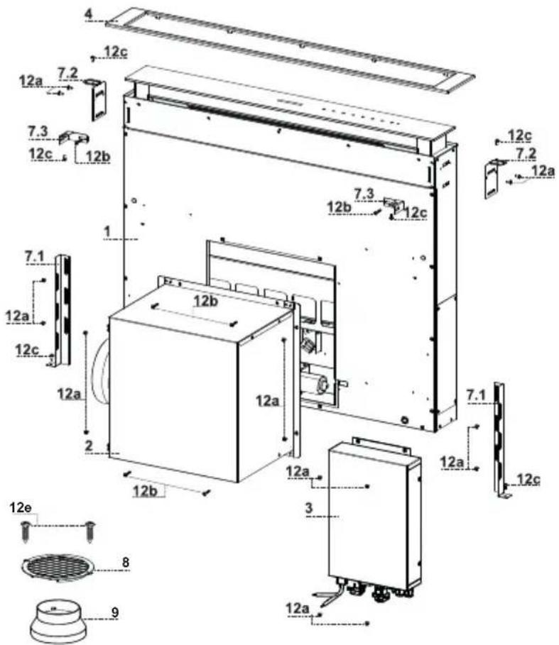
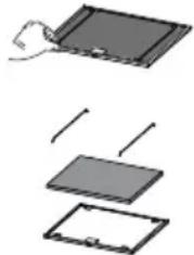
Components
| Ref. | Q.ty | Product Components |
| 1 | 1 | Hood Canopy complete with: Controls, Light, Filters |
| 2 | 1 | Motor unit |
| 3 | 1 | Electric unit |
| 4 | 1 | Front Frame |
| 8 | 1 | Directional Air Outlet grille |
| 9 | 1 | Reducer Flange ø 150-120 mm |
| Ref. | Q.ty | Installation Components |
| 7.1 | 2 | Splashback Fixing Bracket |
| 7.2 | 2 | Hob Fixing Bracket |
| 7.3 | 2 | Side Bracket |
| 12a | 16 | Screws 3.5 x 9.5 |
| 12b | 6 | Screws M4 x 8 |
| 12c | 6 | Screws 4 x 15 |
| 12e | 2 | Screws 2.9 x 9.5 |
| Q.ty | Documentation | |
| 1 | Instruction Manual |
This Hood is set up to be fitted inside the kitchen unit in:
- Ducting version: Evacuation to the outside.
- Recirculation version: Internal recirculation.
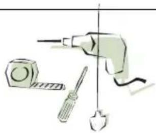
Sequence of operations - Installation
- Drilling the Support Surface and Fitting the Hood
- Connections
- Functional Check
- Disposal of Packaging
natural_image
Illustration of a tool with a drill, screwdriver, and bulb (no text or symbols)Drilling the Support Surface
IMPORTANT
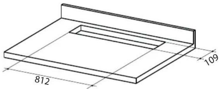
The minimum distance between the opening for the hob and the one for the hood must be of at least 3-5 cm according to the strength of the material used for the working top.
Inserting the Hood Canopy into the support surface from below
• The Hood is built ready for front installation of the Motor Unit.
natural_image
Technical line drawing of a mechanical assembly with two components, no visible text or symbols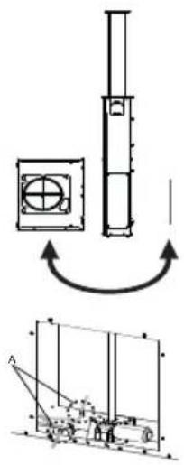
natural_image
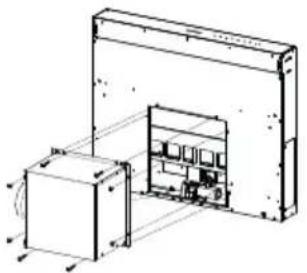
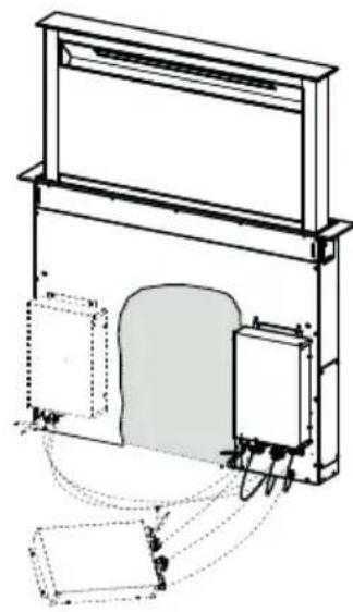
Technical diagram showing a mechanical assembly with a cylindrical component and a schematic of its internal structure (no text or labels)- If the kitchen unit is arranged differently and the Motor Unit has to be fitted on the back, the Plug already fitted on the back of the Hood Canopy must be removed and replaced at the front, and the Cable with cable raceway for connection of the Motor must also be repositioned using the slot provided on each side (A).
Before proceeding, the Motor Unit must be fixed to the Hood Canopy (see paragraph on Fixing the Motor Unit).
- Insert the Hood Canopy from below into the support worktop, drilled as described above.
- With the aid of a support, lift the Hood Canopy until the front comes out of the Worktop.

flowchart
graph TD
    A["Device with internal components"] -->|Feedback| B["Control Panel with labeled components"]
    B --> C["Output"]
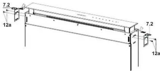
- Insert the Brackets 7.2, as indicated in the figure, into the slots provided and fix them with the screws 12a provided.
- Centre the Hood Canopy with respect to the Cooking Hob slot.
- Using the 2 screws 12c provided, fix the Hood Canopy to the worktop and remove the supports.
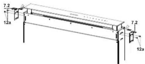
Warning:
If the cooker top is made from a material that does not allow the screws 12c to be inserted, use a small amount of silicone to glue the Brackets 7.2 to the top and allow it to dry completely before proceeding with installation
- Insert the Brackets 7.2, as indicated in the figure, into the slots provided and fix them with the screws 12a provided.
• The Hood is bu ready for front stallation of the Motor Unit.
natural_image
Technical line drawing of a mechanical assembly with two components, one rectangular and one rectangular, showing internal components (no text or symbols)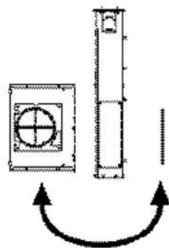
natural_image
Pure mechanical diagram showing a square component with a crosshair and a vertical shaft, connected by curved arrows (no text or symbols)- If the kitchen unit is arranged differently and the Motor Unit has to be fitted on the back, the Plug already fitted on the back of the Hood Canopy must be removed and replaced at the front, and the Cable with cable raceway for connection of the Motor must also be repositioned using the slot provided on each side (A).

natural_image
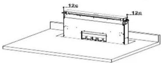
Pure technical diagram of a mechanical assembly without any text, numbers, or symbols- Insert the Hood Canopy into the cooker top, drilled as described above.
- Centre the Hood Canopy with respect to the Cooking Hob slot.
- Fix the Hood Canopy with the 2 screws 12c provided.
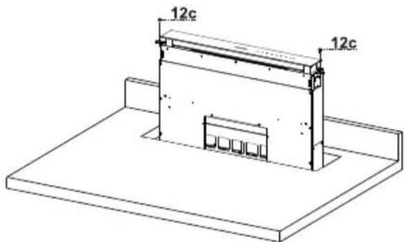
Warning:
If the cooker top is made from a material that does not allow the screws 12c to be inserted, use a small amount of silicone to glue the Brackets 7.2 to the top and allow it to dry completely before proceeding with installation.
- Screw the brackets 7.1 to the front of the Hood Canopy using the screws 12a provided.
- Before tightening the Brackets completely, make all the adjustments to allow them to rest on the lower base of the worktop to avoid deformation of the upper brackets 7.2 as shown in the figure.
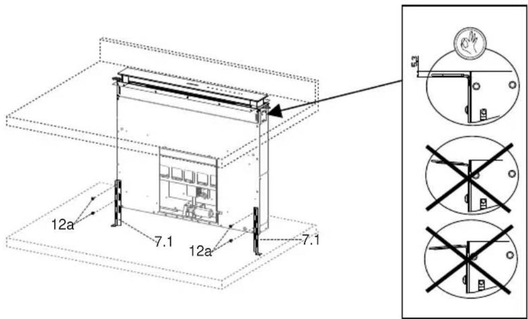
- With the aid of a spirit level, set the Hood Canopy level vertically and fix it to the Lower Surface using 2 screws 12c provided.
natural_image
Technical line drawing of a mechanical assembly with labeled component '12c' (no readable text or symbols beyond label)- Tighten the screws 12a completely.
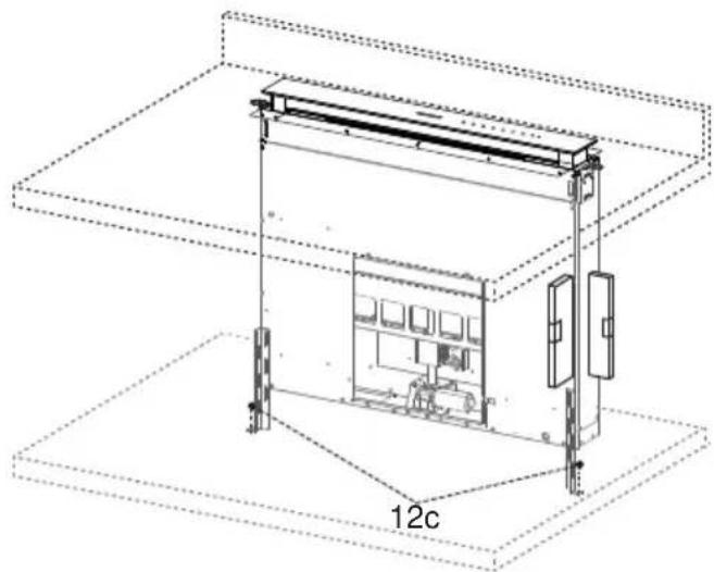
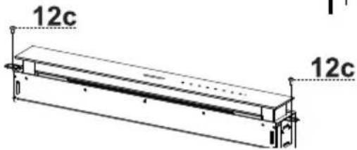
- Screw the brackets 7.3 to the Hood Canopy using the screws 12b provided, without tightening completely.
- Using the screws 12c provided, fasten the other part of the brackets 7.3 either to the side walls of the unit or to the lower part of the cooker top.

- Tighten the screws 12c and 12b completely.
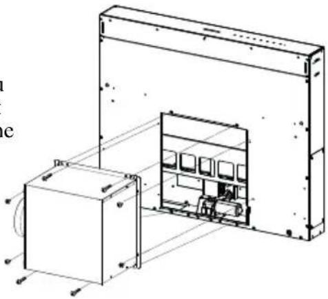
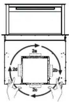
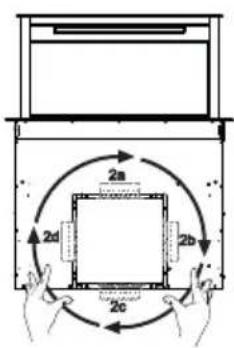
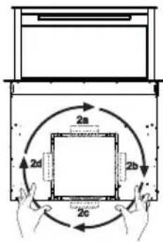
- Installation of the Motor Unit (1) at the front or rear must be decided according to the position of the Kitchen unit, making sure that the plug is properly positioned.
- Subsequently, according to where the air outlet opening has been created on the unit, the Motor Unit can be turned by 90^ at a time so as to allow the air to come out on all 4 sides in correspondence with the opening in Unit (2).
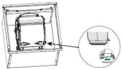
- Connect the connector from the Hood Canopy to the Motor Unit connection.
- Screw the Motor Unit to the Hood Canopy using the screws 12a and 12b provided as shown in the figure.
1

natural_image
Pure mechanical diagram showing a vertical shaft and two circular components with cross symbols, no text or labels present.2

natural_image
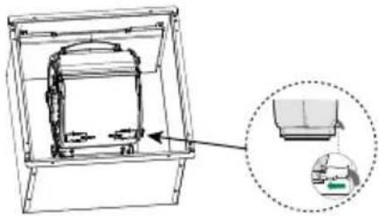
Technical line drawing of a mechanical assembly inside a frame, with an inset showing a close-up view of a component (no text or symbols present)
- Connect the Electric cables that come out of the lower right hand part of the Hood Canopy to the Connectors on the Electric unit.
• Each cable connector has a corresponding connector on the Electric Unit, so take care not to make mistakes when connecting up.
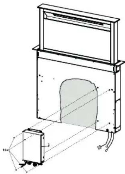
- Fix the Electric Unit to the Hood Canopy using the screws 12a provided.
- The position indicated in the figure is only an option, as if necessary it may also be fitted on the left of the Hood Canopy or even left free on the base of the unit if there are no structural or safety problems involved.
natural_image
Technical line drawing of a mechanical assembly with no visible text or symbols⚠ Warning.: Do not install the product in such a way that the wiring box is in contact with the floor.
Connections
DUCTED VERSION AIR EXHAUST SYSTEM
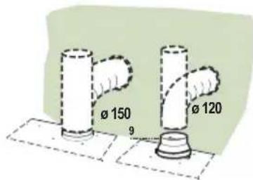
When installing the ducted version, connect the hood to the chimney using either a flexible or rigid pipe 150 or 120 mm, the choice of which is left to the installer.
- To install a 120 mm air exhaust connection, insert the reducer flange 9 on the hood body outlet.
- Fix the pipe in position using sufficient pipe clamps (not supplied).
- Remove possible charcoal filters.
AIR OUTLET – RECIRCULATION VERSION
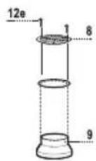
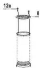
- Connect the Flange to the air outlet opening using a rigid or flexible pipe of 120 or 150mm .
- To connect using a 120 mm pipe, insert the reduction Flange 9 onto the Hood canopy outlet.
- Fasten the pipe using suitable pipe clamps. The materials required to do so are not provided.
- Fix the directional Grid 8 on the outlet, using 2 screws 12e (2.9 x 9.5) provided.
- Make sure that the activated charcoal filters are present (see paragraph on Activated Charcoal Filter Maintenance).
ELECTRICAL CONNECTION
- Connect the hood to the mains through a two-pole switch having a contact gap of at least 3 mm..
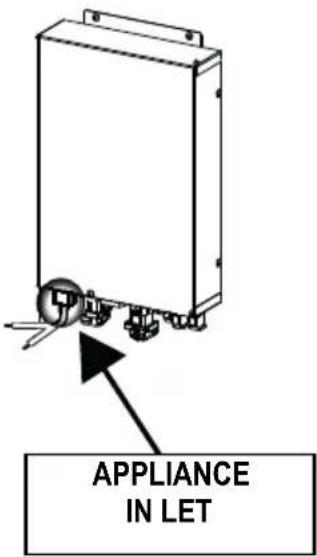
Fitting the Front element
- Lift the mobile hood canopy (see paragraph on Use) by just a few centimetres.
• To stop movement, simply press down on the mobile canopy as it lifts up.
Warning: Never block the sliding door when it is opening or closing, except during the operations required to fit the frame.
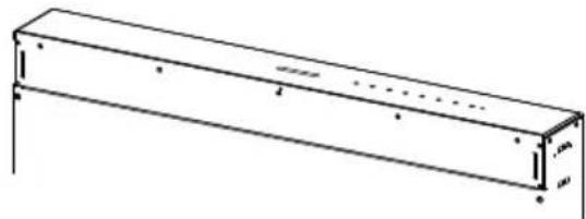
- Remove the sponge guards from the corners of the glass.
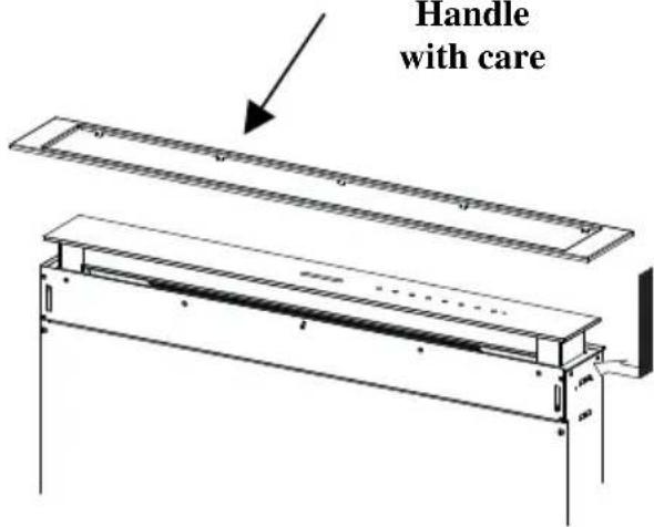
• Take the front Frame and insert it from above, making sure that its tabs insert into the slots provided on the Hood and sliding it to the left.
Warning...: All the tabs must be inserted.
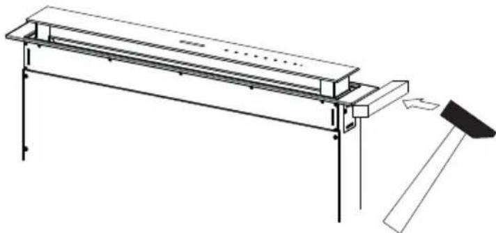
- Use a tool (hammer) to tap all along the front Frame from right to left until it is completely flush.
A piece of wood or similar element can be inserted between the hammer and the front Frame to prevent any damage.
- Please refer to the paragraph on Use for indications of how to return the mobile canopy to the Standard position.
natural_image
Pure technical line drawing of a rectangular beam or support structure without any text, numbers, or symbolsWarning...:
Handle
with care
natural_image
Technical line drawing of a mechanical assembly with a handle and base plate (no text or symbols)
natural_image
Line drawing of a long rectangular metal frame with supports and mounting feet (no text or symbols)- Open the Hood Door (see USE).
- Remove the 2 strips of adhesive tape fastening the panel during transport.
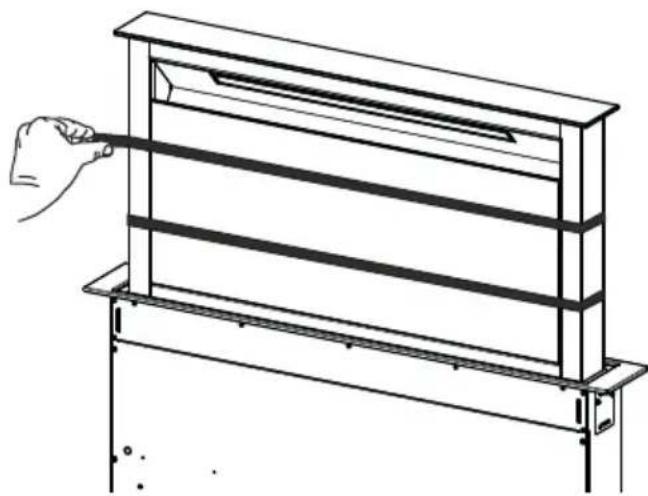
natural_image
Line drawing of a hand holding a rectangular shelf with horizontal bars, mounted on a metal frame (no text or symbols)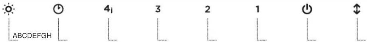
Control panel
| Button | Function LED button | |
| A The | button only works when the door is open. | |
| Press Briefly = Turns the Lights On/Off at maximum intensity. | ||
| Press and hold for 2 Seconds = Turns the Courtesy Lights On/Off. | ||
| B Only works with the Door Open.Press briefly = Activates/Deactivates Delay mode, causing automatic shutdown of the Motor and the Lighting system from any speed with a 30' delay. It is disabled by pressing the same button again, turning the motor off or closing the door. | LED Button B+ Button for the set Speed are lit. | |
| C Only works with the Door Open.Press briefly = Activates speed four. | Fixed LED button:Indicates the need to wash the metal grease filters.The alarm is triggered after the Hood has been in operation for 100 working hours.Fashing LED button:Indicates the need to change the activated charcoal filters, and also to wash the metal grease filters. The alarm is triggered after the Hood has been in operation for 200 working hours. | |
| D Only works with the Door Open.Activates speed three. | Fixed LED button | |
| Only works with the Door Open.Activates/Deactivates speed two. | Fixed LED button E | |
| Works both with Door Closed and Open with Motor + Lights = Off.Press and hold for 4 Seconds = Enables/disables the Keyboard lock. | All the LED buttons flash twice. During the Lock the LED buttons light up in sequence. | |
| F Only works with the Door Open.Press briefly = Activates/Deactivates speed one. | Fixed LED button | |
| G Door OpenPress briefly = Turns the Motor off | LED button B flashes twice = Activated Charcoal filter Alarm ActivatedLED button B flashes once = Activated Charcoal filter Alarm Deactivated | |
| H | Door Open = Closes the Door + Lights and Motor OffDoor Closed = Opens the Door + Lights and Motor On.Warning: If the Door remains partially open for any reason, press the Button to complete the opening or closing cycle. | |
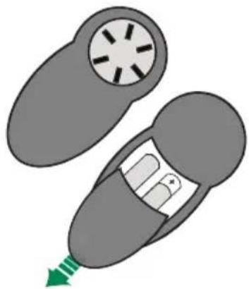
REMOTE CONTROL (OPTIONAL)
The appliance can be controlled using a remote control powered by a 1.5 V carbon-zinc alkaline batteries of the standard LR03-AAA type (not included).
- Do not place the remote control near to heat sources.
- Used batteries must be disposed of in the proper manner.
natural_image
Illustration of a car with a circular head and internal components, showing a green arrow pointing to the bottom (no text or symbols)Remote control panel
Warning.: The remote control receiver is deactivated when first supplied. To activate it, see the paragraph Use.

| Motor | Door Closed:Opens the door, turns the motor on at speed one and turns the lights on at maximum intensity. | |
| Door Open:Brief pressure: Motor On / OffPressed for 2 Seconds: Closes the Door and Motor + Lights = Off | ||
| - | Only with Door Open:Decreases the working speed each time it is pressed. | |
| + | Only with Door Open:Increases the working speed each time it is pressed. | |
| i | Intensive | Only with Door Open:Activates the Intensive function |
| ∅ | Delay | Only with Door Open:Activates the Delay function |
| Light | Only with Door Open:Brief pressure: Lights On / OffPressed for 2 Seconds: Courtesy lights On / Off |
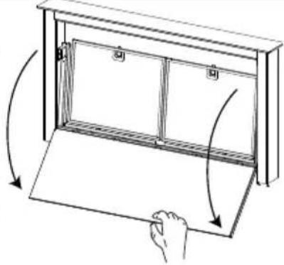
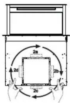
Cleaning the Comfort Panels
- Open the Comfort Panel by pulling it at the top.
- Disconnect the panel from the hood canopy.
- The comfort panel must never be washed in the dishwasher.
- Clean the outside with a damp cloth and neutral detergent.
- Clean the inside using a damp cloth and neutral detergent; do not use wet cloths or sponges, or jets of water; do not use abrasive substances.
- On completing the operation, hook the panel and close it.
natural_image
Diagram of a cabinet with arrows indicating rotation and movement, no text or symbols presentMetal grease filters
These can also be washed in the dishwasher, and need to be cleaned whenever button B lights up or at least once every 2 months use, or more frequently if use is particularly intensive.
Resetting the alarm signal
- Turn the Lights and the Suction Motor off.
- Press and hold button B for 2 seconds.
Cleaning the Filters
- Open the Door (see USE).
- Open the Comfort panel by pulling it.
- Remove the Filters one at a time, pushing them towards the back of the unit and at the same time pulling downward.
- Wash the Filters without bending them, and leave them to dry completely before replacing. (If the surface of the filter changes colour as time goes by, this will have absolutely no effect on the efficiency of the filter itself.)
- Replace, taking care to ensure that the handle faces forwards.
- Close the Comfort panel.

natural_image
Hand inserting a green arrow on a smartphone screen (no text or symbols visible)Activated Charcoal Filter (Recirculation Version)
Can be washed in the dishwasher. It must be washed when button B flashes or at least once every 4 months, or more frequently if use is particularly intense. Guaranteed to operate after washing for up to a maximum of 5 times before requiring replacement. The Alarm signal, if it has been activated, only appears when the Suction motor is turned on.
Activating the alarm signal
- In Recirculation Version Hoods, the Filter Saturation Alarm must be activated on installation or at a later date.
- Turn the Lights and the Suction Motor off.
- Press and hold button F for 2 seconds:
- LED B flashes twice – Activated Charcoal Filter saturation alarm ACTIVATED.
- LED B flashes once – Activated Charcoal Filter saturation alarm DEACTIVATED.
CHANGING THE ACTIVATED CHARCOAL FILTER
Resetting the alarm signal
- Turn the Lights and the Suction Motor off.
- Press and hold button B for 2 seconds.
natural_image
Diagram showing three steps of a device being folded or placed, with no visible text or symbols.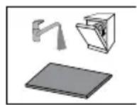
Changing the Filter
- Remove the comfort panel.
- Remove the Metal grease filters.
- Remove the metal filter stops from the grease filter and clean the saturated activated charcoal odour filter.
- Replace the clean activated charcoal odour filter, hooking it back up to the grease filter using the metal filter stops.
- Replace the Metal grease filters.
- Close the comfort panel.
Lighting unit
- For replacement contact technical support ("To purchase contact technical support").
COMMERCIAL GUARANTEE AND GUARANTEE FOR AFTER SALES SERVICE
COMMERCIAL GUARANTEE
The commercial guarantee provided by FRANKE FRANCE SAS for products of the ROBLIN brand is limited to distribution professionals. It is applicable in continental France, Corsica and the DOM-TOM (French overseas departments and territories).
The commercial guarantee is a guarantee of 2 years for parts (excluding labour and travel expense). It applies starting from the billing date for the equipment to the consumer, provided that this occurs in the 12 months following the date of sale by ROBLIN to the Customer.
In order to satisfy the consumer at the time of any intervention by the after-sales service department, the Customer agrees to direct it to the service put in place by ROBLIN in order to organise the service intervention as quickly as possible. The after-sales service department may be contacted at the following number: 04 88 78 59 93.
The items to be provided to the ROBLIN after-sales service department are:
• A description of the malfunction observed
- The commercial reference of the product and its serial number
- A copy of the purchase invoice of the consumer and his contact information.
This guarantee applies to any technical or functional problems. The following are excluded from the commercial guarantee:
- Breakdowns related to accessories or consumables (filters, bulbs...),
- Damage, malfunctions or defects attributable to external causes,
- Damage due to corrosion, improper connection or feed,
- Damage due to non-respect of the instructions provided by ROBLIN (installation, assembly...),
- Breakdowns resulting from modification of the construction and characteristics of equipment of the ROBLIN brand,
- Breakdowns and damage occurring after use of spare parts which do not correspond to those provided originally by ROBLIN, or due to an absence of maintenance,
- Breakdowns resulting from professional or commercial use of the equipment.
AVAILABILITY OF SPARE PARTS
In application of article R 111-3 of the Consumer Code, for products placed on the market starting from 1 March 2015, ROBLIN guarantees the availability of the spare parts necessary for use of its Products for a period of 10 years following purchase of the product by the consumer, with the invoice being deemed as proof, provided that dated within the 12 months following the date of sale by ROBLIN to the Customer.
natural_image
Illustration of a chemical experiment setup with a conical flask, test tube, and control panel (no text or symbols)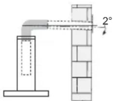
natural_image
Illustration of a greenhouse with a stove and smokestack, crossed by a green ribbon (no text or symbols)natural_image
Illustration of a hand holding a tool, a screwdriver, and a pushpin (no text or symbols)natural_image
Technical line drawing of a mechanical assembly with two components, no visible text or symbolsnatural_image
Pure mechanical component diagram showing a square plate with a circular hole and a vertical cylindrical shaft, no text or symbols present.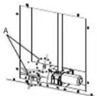
natural_image
Technical line drawing of a mechanical assembly with two components, one rectangular and one rectangular, showing internal components (no text or symbols)natural_image
Pure mechanical diagram showing a shaft and housing with a circular component, no text or symbols present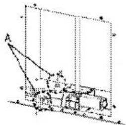
natural_image
Pure mechanical diagram showing a lever and shaft assembly without any text, numbers, or symbolsnatural_image
Technical line drawing of a mechanical assembly with labeled component '12c' (no text or symbols beyond label)natural_image
Diagram of a vertical structure with circular elements and directional arrows, no text or symbols present2
natural_image
Technical line drawing of a mechanical assembly with a magnified inset showing internal components (no text or symbols)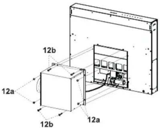
natural_image
Technical line drawing of a mechanical assembly with a housing and component, showing dimension lines (no text or symbols)natural_image
Technical line drawing of a mechanical assembly with no visible text or symbolsnatural_image
Technical line drawing of a mechanical frame with a hammer and base, no text or symbols present
natural_image
Line drawing of a long rectangular table with supports and a small protrusion (no text or symbols)natural_image
Line drawing of a hand holding a rectangular shelf with horizontal bars, mounted on a support frame (no text or symbols)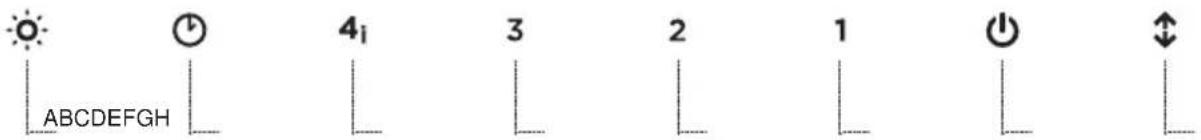
Schalttafel
natural_image
Diagram of a car with a circular head and internal components, showing a green arrow pointing to the bottom section (no text or symbols present)natural_image
Diagram of a hand holding a rectangular object with arrows indicating rotation or movement (no text or symbols)Metallfettfilter
natural_image
Hand inserting a device into a screen, showing green arrow indicating direction (no text or symbols)natural_image
Diagram showing three stages of a device with a handle and cable, no text or symbols present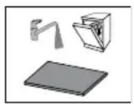
Beleuchtung
LED-Strahler
natural_image
Illustration of a kitchen induction setup with a smokestack emitting vapor and a control panel (no text or symbols)natural_image
Illustration of a greenhouse with a stove and soil, crossed by a green ribbon (no text or symbols)natural_image
Illustration of a hand holding a screwdriver, a nut, and a plow (no text or symbols)natural_image
Technical line drawing of a mechanical assembly with two components, one rectangular and one rectangular, showing internal components (no text or symbols)
natural_image
Pure mechanical component diagram with no text, numbers, or symbolsnatural_image
Technical line drawing of a mechanical or electrical enclosure with labeled component '12c' (no text or symbols beyond label)• Fissare definitivamente le Viti 12a.
natural_image
Pure mechanical diagram showing a vertical shaft connected to a square component with circular holes, no text or symbols present.2
natural_image
Technical line drawing of a mechanical assembly with an inset showing a component (no text or symbols present)
natural_image
Technical line drawing of a mechanical assembly with no visible text or symbolsnatural_image
Technical line drawing of a mechanical assembly with no visible text or symbolsnatural_image
Pure technical line drawing of a rectangular beam with supports and hidden lines (no text or symbols)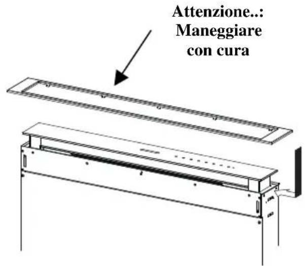
natural_image
Technical line drawing of a mechanical frame assembly with a hammer and lever (no text or symbols)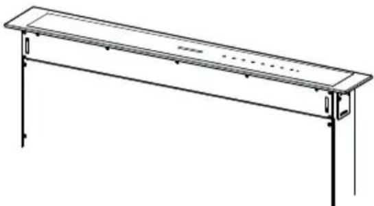
natural_image
Line drawing of a long rectangular metal frame with supports and mounting brackets (no text or symbols)natural_image
Line drawing of a hand holding a rectangular shelf with horizontal bars, mounted on a metal frame (no text or symbols)
Quadro comandi
natural_image
Diagram of a device with a circular component and internal components, showing a green arrow pointing to it (no text or symbols present)Quadro comandi Telecomando
natural_image
Diagram of a cabinet with arrows indicating rotation and movement, no text or symbols presentnatural_image
Illustration of a hand pressing a green arrow on a device screen (no text or symbols)natural_image
Illustration of three-step battery pack assembly: top shows a tray with cable, bottom shows a slide with plug and switch (no text or symbols)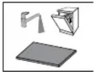
natural_image
Illustration of a chemical experiment setup with a conical flask, smoke rising, and a control panel (no text or symbols)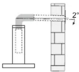
natural_image
Illustration of a greenhouse with a container and a crossed green ribbon, no text or symbols present.natural_image
Illustration of a hand holding a screwdriver, a nut, and a shovel (no text or symbols)natural_image
Technical line drawing of a mechanical assembly with two components, no visible text or symbols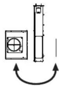
natural_image
Pure mechanical component diagram showing a square plate with a circular hole and a cylindrical shaft, no text or symbols present.natural_image
Technical line drawing of a mechanical assembly with two components, one rectangular and one rectangular, showing internal components (no text or symbols)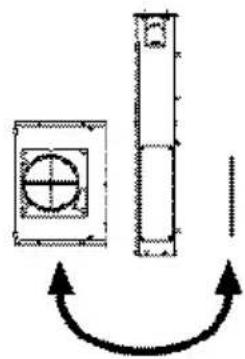
natural_image
Pure mechanical diagram showing a shaft and housing with curved arrows indicating motion (no text or symbols)natural_image
Diagram of a mechanical device with labeled components and alignment lines (no readable text or symbols)natural_image
Technical line drawing of a mechanical or electrical enclosure with labeled component '12c' (no readable text or symbols beyond label)natural_image
Diagram of a vertical structure with circular elements and directional arrows, no text or symbols present2

natural_image
Technical line drawing of a mechanical assembly with a magnified inset showing a component detail (no text or symbols)
natural_image
Technical line drawing of a mechanical assembly with a housing and component, showing dimension lines (no text or symbols)natural_image
Technical line drawing of a mechanical assembly with no visible text or symbolsnatural_image
Pure technical line drawing of a rectangular structural component with no text or symbols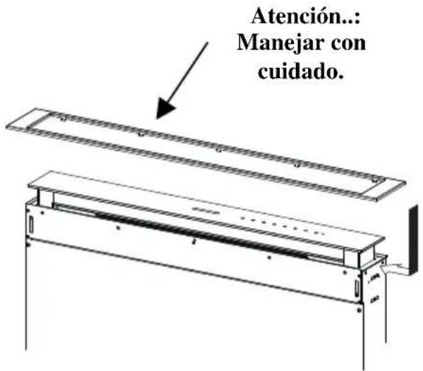
natural_image
Technical line drawing of a mechanical assembly with a handle and base plate (no text or symbols)
natural_image
Line drawing of a long rectangular metal frame with supports and mounting brackets (no text or symbols)natural_image
Line drawing of a hand holding a rectangular frame with horizontal bands, no text or symbols present
Tablero de mandos
natural_image
Illustration of a car with a circular head and hand panel, showing a green arrow pointing to the bottom-right corner (no text or symbols)natural_image
Diagram of a cabinet with arrows indicating rotation and movement, no text or symbols presentnatural_image
Hand inserting a green arrow on a smartphone screen (no text or symbols)natural_image
Diagram showing three steps of a device being processed from top, middle, and bottom views (no text or symbols)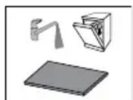
Iluminación
natural_image
Illustration of a chemical experiment setup with a conical flask, thermometer, and smoke (no text or symbols)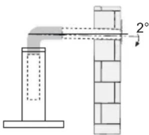
natural_image
Illustration of a greenhouse with a stove and a crossed green cross symbol (no text or labels)natural_image
Illustration of a hand holding a screwdriver, a tool, and a flat screwdriver (no text or symbols)natural_image
Technical line drawing of a mechanical assembly with two components, no visible text or symbols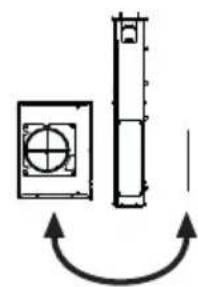
natural_image
Pure mechanical component diagram with no text, numbers, or symbolsnatural_image
Pure mechanical diagram showing a pulley system with no text, numbers, or symbolsflowchart
graph TD
    A["Device with internal components"] --> B["Control Panel"]
    B --> C["Arrow indicating direction of feedback loop"]

Let op:
natural_image
Technical line drawing of a mechanical assembly with two components, one rectangular and one rectangular, showing internal components (no text or symbols)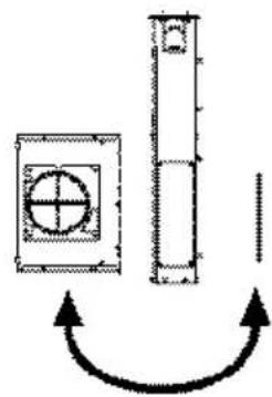
natural_image
Pure mechanical diagram showing a shaft and plate assembly with no text or symbolsnatural_image
Pure mechanical diagram showing a lever system with no text, numbers, or symbolsnatural_image
Technical line drawing of a mechanical assembly with labeled component '12c' (no readable text or symbols beyond label)natural_image
Pure mechanical diagram showing a vertical shaft connected to a square component with circular holes, no text or symbols present.2


natural_image
Technical line drawing of a mechanical assembly with an inset showing a component (no text or symbols present)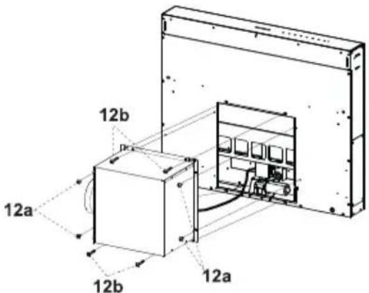
natural_image
Technical line drawing of a mechanical assembly with no visible text or symbolsnatural_image
Technical line drawing of a mechanical assembly with no visible text or symbolsnatural_image
Pure technical line drawing of a rectangular beam or support structure without any text, numbers, or symbols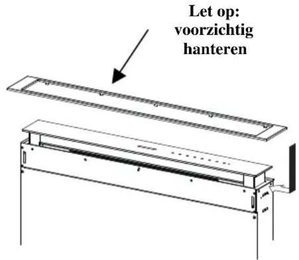
natural_image
Technical line drawing of a mechanical frame assembly with a hammer and lever (no text or symbols)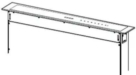
natural_image
Line drawing of a long rectangular table with supports and a small plate, no text or symbols presentnatural_image
Line drawing of a hand holding a rectangular frame with horizontal bands, no text or symbols present
Bedieningspaneel
natural_image
Illustration of a device with a circular component and a green arrow pointing to it (no text or symbols)natural_image
Diagram of a hand holding a rectangular object with arrows indicating rotation or movement (no text or symbols)Metalen vetfilters
natural_image
Hand holding a smartphone with a green arrow indicating left touch (no text or symbols)natural_image
Three-step diagram showing a device being folded into a flat panel, with no text or symbols present.
Verlichting

- SOMMAIRE
- FR
- INDEX
- EN
- INHALTSVERZEICHNIS
- DE
- Éclairage
- INSTALLATION
- USE
- MAINTENANCE
- Sequence of operations - Installation
- Drilling the Support Surface
- IMPORTANT
- Inserting the Hood Canopy into the support surface from below
- Warning:
- Connections
- DUCTED VERSION AIR EXHAUST SYSTEM
- AIR OUTLET – RECIRCULATION VERSION
- ELECTRICAL CONNECTION
- Fitting the Front element
- REMOTE CONTROL (OPTIONAL)
- Remote control panel
- Cleaning the Comfort Panels
- Metal grease filters
- Resetting the alarm signal
- Cleaning the Filters
- Activated Charcoal Filter (Recirculation Version)
- Activating the alarm signal
- CHANGING THE ACTIVATED CHARCOAL FILTER
- Changing the Filter
- Lighting unit
- COMMERCIAL GUARANTEE AND GUARANTEE FOR AFTER SALES SERVICE
- COMMERCIAL GUARANTEE
- AVAILABILITY OF SPARE PARTS
- Metallfettfilter
- Beleuchtung
- LED-Strahler
- Quadro comandi Telecomando
- Iluminación
- Let op:
- Metalen vetfilters
- Verlichting
Brand : ROBLIN
Model : Elina
Category : Basket