Vizio 2 - Basket ROBLIN - Free user manual and instructions
Find the device manual for free Vizio 2 ROBLIN in PDF.
User questions about Vizio 2 ROBLIN
0 question about this device. Answer the ones you know or ask your own.
Ask a new question about this device
Download the instructions for your Basket in PDF format for free! Find your manual Vizio 2 - ROBLIN and take your electronic device back in hand. On this page are published all the documents necessary for the use of your device. Vizio 2 by ROBLIN.
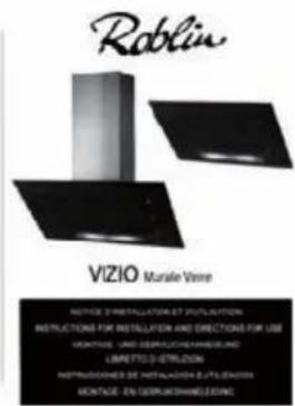
USER MANUAL Vizio 2 ROBLIN
Instructions for use and installation
Cooker Hood

natural_image
Three black industrial kitchen appliances displayed against a white background (no text or symbols visible)FITTING THE APPLIANCE
OPERATION
USEFUL HINTS
MAINTENANCE
GUARANTEE AND AFTER-SALES-SERVICES
REMARKS
D INHALT
NETZANSCHLUSS
MONTAGEHILFEN
MONTAGE DES GERÄTES
BETRIEB DES GERÄTES
NUTZUNG
text_image
E 24h F G HThank you for buying a Roblin product which has been manufactured to the highest quality standards to meet your requirements.
We recommend you carefully read this booklet in which you will find instructions for installation, hints for use and maintenance.
The Instructions for Use apply to several versions of this appliance. Accordingly, you may find descriptions of individual features that do not apply to your specific appliance.
1 ELECTRICAL
- This cooker hood is fitted with a 3-core mains cable with a standard 10/16A earthed plug.
• Alternatively the hood can be connected to the mains supply via a double-pole switch having 3mm minimum contact gap on each pole. - Before connecting to the mains supply ensure that the mains voltage corresponds to the voltage on the rating plate inside the cooker hood.
- Technical Specification: Voltage 220-240, single phase \~50/60Hz.
2 INSTALLATION ADVICE
- Ensure the cooker hood is fitted in compliance with the recommended fixing heights.
- To ensure the safe operation of this cooker hood, we recommend that the hood should not be fitted below 65cm (for electric) or (70cm for gas) the measurements taken from the surface of the cooking appliance to the underside of the cooker hood.
- It is a possible fire risk if the hood is not sited as recommended.
- To ensure the best results, the cooking fumes should be able to rise naturally towards the inlet grilles on the underside of the cooker hood and the cooker hood should be positioned away from doors and windows, which will create turbulence.
- Ducting
- If the room where the hood is to be used contains a fuel-burning appliance such as a central heating boiler then its flue must be of the room sealed or balanced flue type.
- If other types of flue or appliances are fitted ensure that there is an adequate supply of fresh air to the room. Ensure the kitchen is fitted with an airbrick, which should have a cross-sectional measurement equivalent to the diameter of the ducting being fitted, if not larger.
- The ducting system for this cooker hood must not be connected to any existing ventilation system, which is being used for any other purposes or to a mechanically controlled ventilation ducting.
- The ducting used must be made from fire retardant materials and the correct diameter must be used, as incorrect sized ducting will affect the performance of this cooker hood.
- When the cooker hood is used in conjunction with other appliances supplied with energy other than electricity, the negative pressure in the room must not exceed 0.04 mbar to prevent the fumes from combustion being drawn back into the room.
- The appliance is for domestic use only and should not be operated by children or people who are infirm without supervision.
- This appliance must be positioned so that the wall socket is accessible.
- This appliance is not intended for use by persons (including children) with reduced physical, sensory or mental capabilities, or lack of experience and knowledge, unless they have been given supervision or instruction concerning use of the appliance by a person responsible for their safety.
Children should be supervised to ensure that they do not play with the appliance.
3 FITTING
Any permanent electrical installation must comply with the latest regulations concerning this type of installation and a qualified electrician must carry out the work. Non-compliance could cause serious accidents or injury and would deem the manufacturers guarantee null and void.
IMPORTANT - The wires in this mains lead are coloured in accordance with the following code :
- green / yellow : earth
- blue : neutral
- brown : live
As the colours of the wires in the mains lead of this appliance may not correspond with the coloured
markings identifying the terminals in your plug, proceed as follows.
- The wire which is coloured green and yellow must be connected to the terminal in the plug which is marked with the letter E or by the earth symbol or coloured green or green and yellow.
- The wire which is coloured blue must be connected to the terminal which is marked with the letter N or coloured black.
- The wire which is coloured brown must be connected to the terminal which is marked with the letter L or coloured red.
ATTENTION: Do not forget to use adequate plugs to the support brackets. Enquire after the manufacturers. Do an embedding if necessary. The manufacturer accepts no responsibility in case of a faulty hanging due to the drilling and the setting up of plugs.
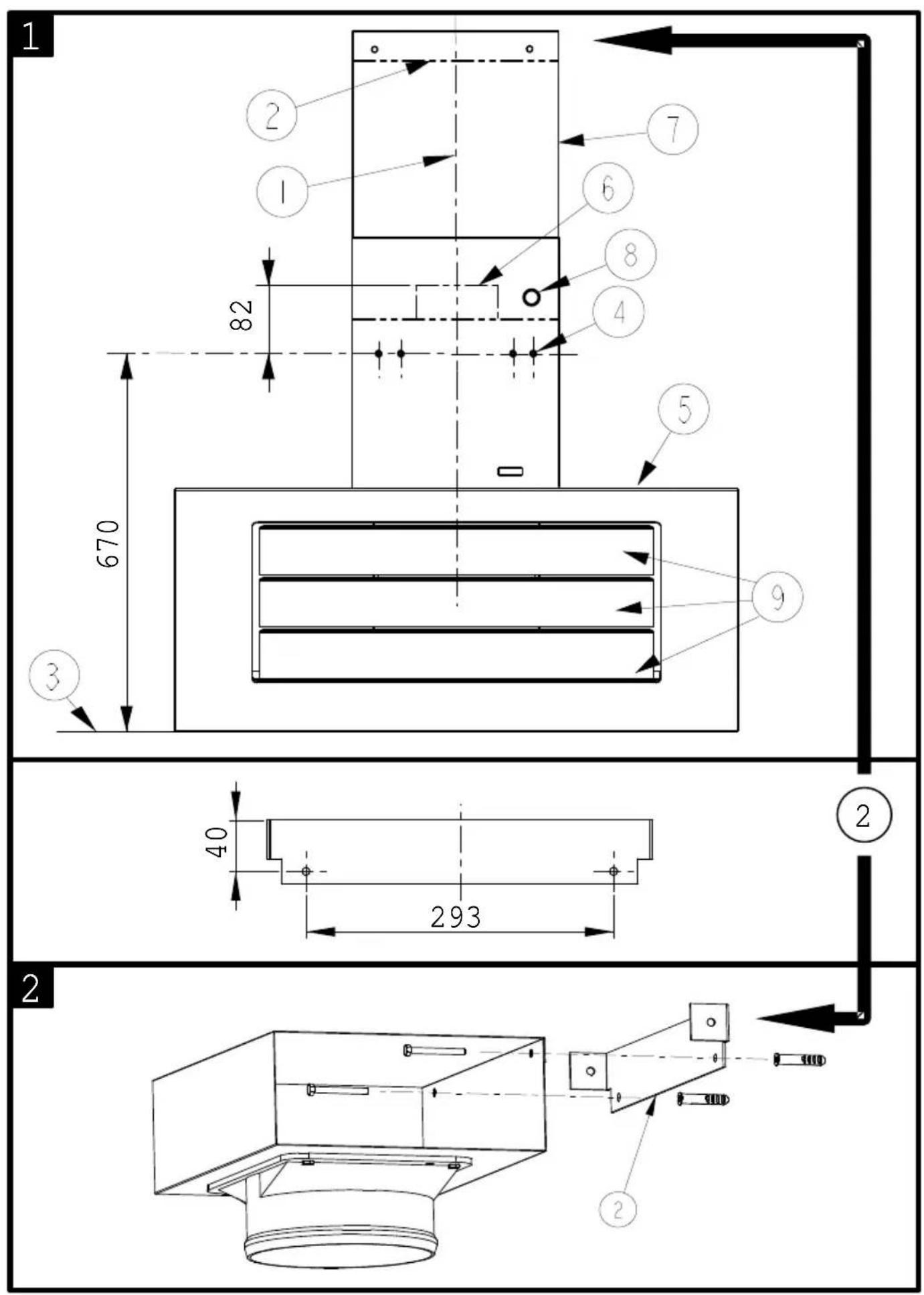
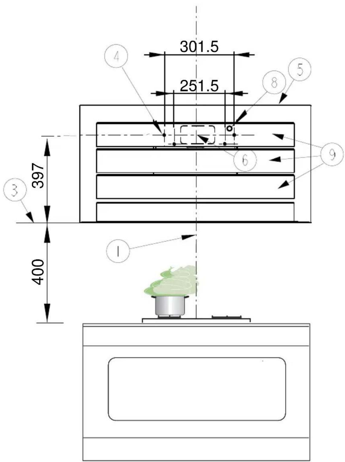
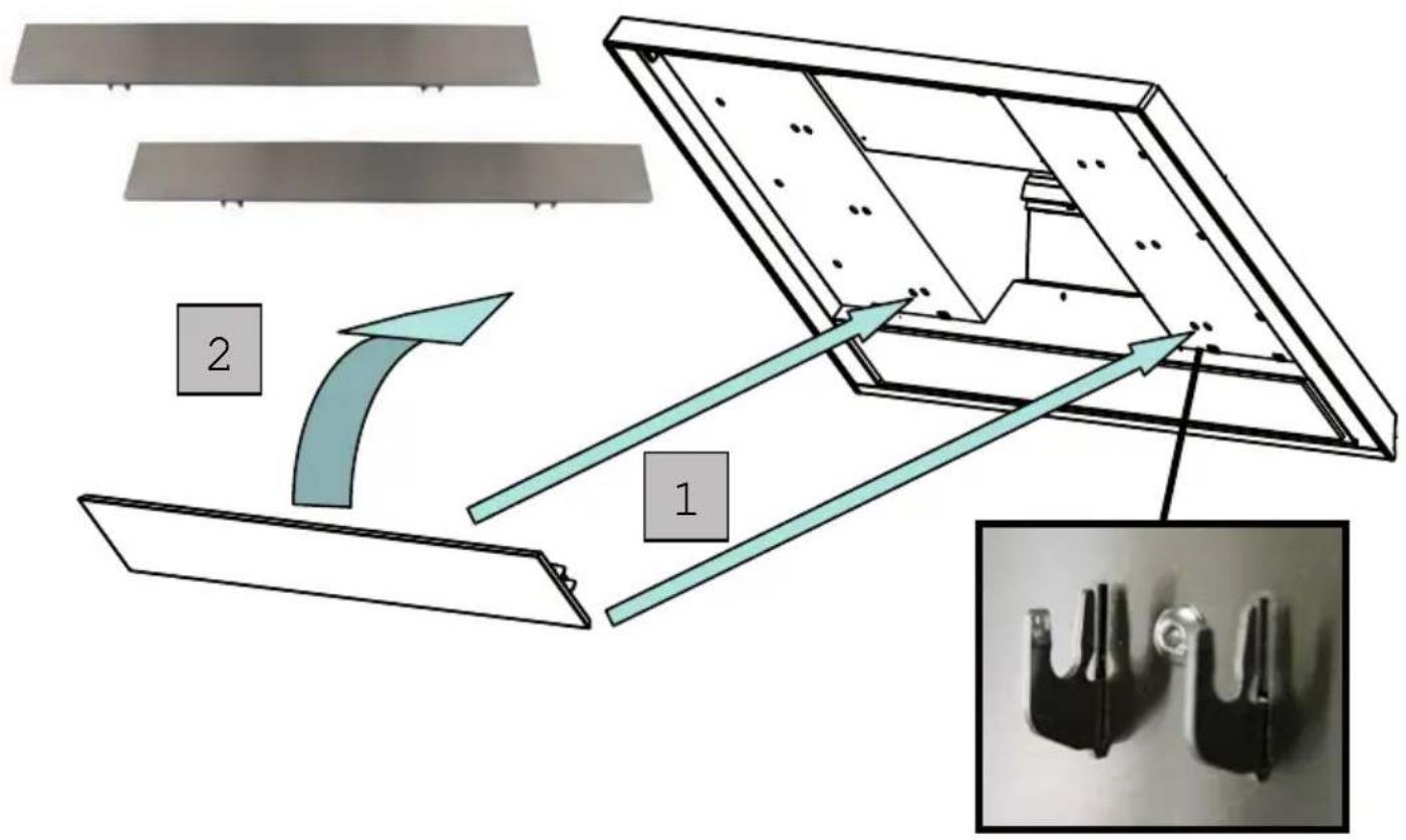
1) Draw a vertical line onto the wall from the centre of the cooking appliance up to the ceiling, using a spirit level and a marker pen as illustrated in Fig. 1 - item 1. This is to ensure the correct alignment of the chimney hood.
2) Place the brackets item 2 on the wall about 1 or 2 mm from the ceiling or from the upper limit, aligning its centre on the vertical line. Mark the two eyelet holes of the bracket onto the wall. Drill the holes for the fixing bracket using an 8 mm masonry bit. Fix the chimney bracket item 2 using the 4.5 x 50 mm screws and rawl plugs supplied.
3) Mark a point on the vertical line at a distance from the cooking appliances of:
$$ d = 1 0 7 0 \mathrm{mm} (\text { Measurement without splashback }). $$
$$ d = \text { height of the splashback } (4 0 0 \mathrm{mm}) + 6 7 0 \mathrm{mm} (\text { Measurement with splashback }). $$
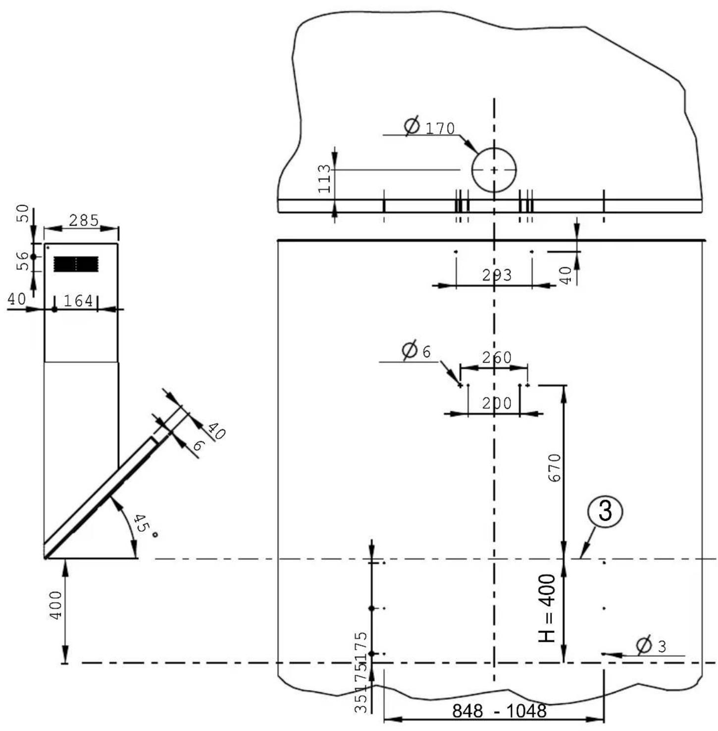
The distance H is the minimum height in mm from the cooking appliances to the bottom edge item 3 of the front panel of the hood. Draw a horizontal line through the vertical as illustrated in Fig. 1.
Splashback (optional): When a splashback is to be fitted, the distance between the hood and the cooking appliances will be determined by the height of the splashback item B and whether or not there is a raised back on the worktop. The splashback is to be installed before installing the canopy. If the splashback is to be fixed to the wall using both the top and bottom fixing holes, Care must be taken to ensure that the splashback is fitted at the correct height before fixing the base units or at least the worktop covering them. As this is a complex operation, it should only be undertaken by the technician installing the kitchen units or by a competent person who knows the final dimensions of the units.
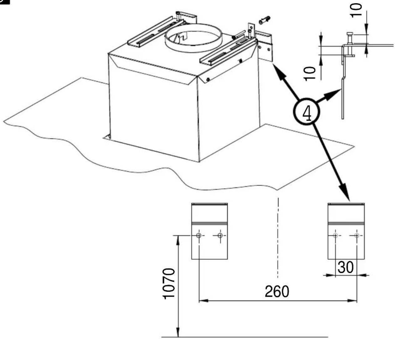
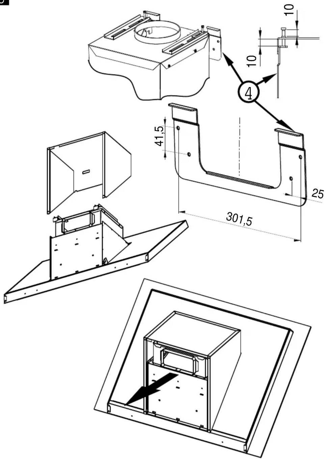
Mark the hole centres for the canopy fixing brackets item 4 at item B mm as illustrated in Fig. 3. Drill the 4 holes for the fixing brackets using an 8 mm masonry bit. Fix the wall brackets item 4 using the 4.5 x 45 mm screws and rawl plugs supplied.
4) Hook the canopy item 5 onto the wall brackets item 4 as illustrated in Fig. 3. To ensure the cooker hood is aligned correctly adjust the screws on the top of the canopy as illustrated in Fig. 3. When the hood is aligned correctly mark the hole centre on the wall for the security fixing screw item8, which is located in the right hand bracket on the top of the canopy. Unhook the canopy from the wall and drill the hole for the security fixing screw. Hook the canopy onto the wall and fix the No 4,5 x 50mm headed screw and rawl plug to secure the canopy to the wall.
5) Ducting:
The hood is more effective when used in the extraction mode (ducted to the outside). When the cooker hood is ducted to the outside, charcoal filters are not required. The ducting used must be 150 mm (6 INS), rigid circular pipe and must be manufactured from fire retardant material, produced to BS.476 or DIN 4102-B1. Wherever possible use rigid circular pipe which has a smooth interior, rather than the expanding concertina type ducting.
Maximum length of ducting run:
- 4 metres with 1 x 90° bend.
- 3 metres with 2 × 90^ bends.
- 2 metres with 3 × 90^ bends.
The above assumes our 150 mm (6 INS) ducting is being installed. Please note ducting components and ducting kits are optional accessories and have to be ordered, they are not automatically sup-
plied with the chimney hood.
IN THE EXTRACTION MODE:
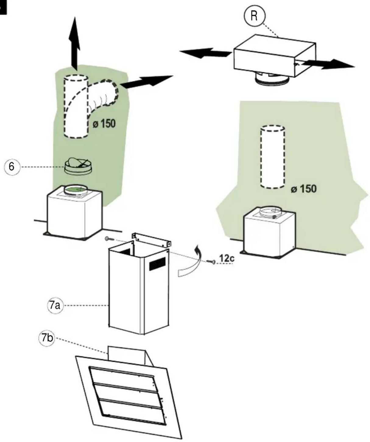
a. Place the anti-backflow flats item 8 over the round outlet item 6, the telescopic duct and connect the ducting 150mm (6 INS) over the round outlet on top of the canopy and secure the connections with appropriate clamping rings or adhesive tape (Fig. 6).
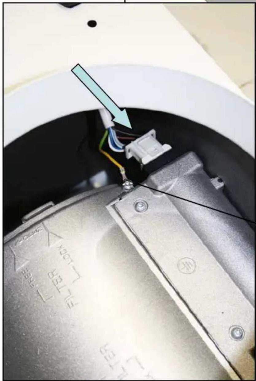
b. Remove the grease filters (see paragraph Maintenance) Fig. 5 being sure that the connector of the mains cable is correctly inserted in the socket placed on the sides of the fan. Before fitting the chimney to the canopy make the electrical connection as described in the section titled ELECTRICAL. When the electrical connection has been made, test the lights and the fan motor.
c. Each chimney stack consists of two sections. Fit the upper sections (Fig. 1 - item 7a & b) first by expanding the chimneys slightly to allow them to clamp around the bracket item 2 and secure the chimney stacks to the brackets using the two M4 screws item 12c provided. Fit the lower chimney sections by expanding the chimneys slightly to allow them from the top of the canopy to clamp around the upper chimney sections.
d. Fit the 3 deflectors Item 9.
IN THE RECIRCULATION MODE:
a. Fit the recirculation spigot R onto the upper chimney wall bracket using the same fixing screws (Fig. 2 item 2).
b. Connect the ducting 150mm (6 INS) not provided between motors item 6 and the recirculation spigot and secure the connections with appropriate clamping rings or adhesive tape.
c. Remove the grease filters (see paragraph Maintenance) Fig. 5 being sure that the connector of the feeding cable is correctly inserted in the socket placed on the side of the fan. Before fitting the chimney to the canopy make the electrical connection as described in the section titled ELECTRICAL. When the electrical connection has been made, test the lights and the fan motor.
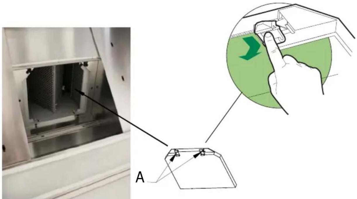
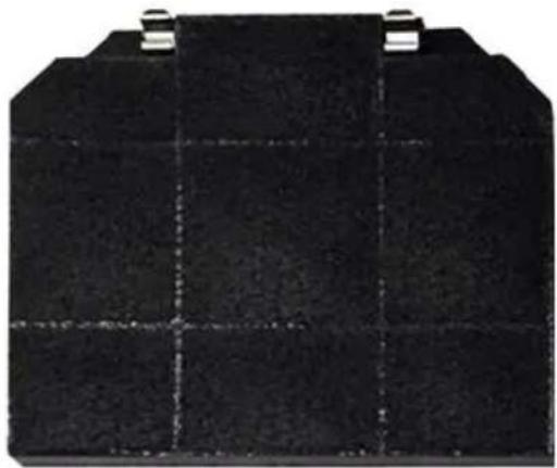
d. Insert the charcoal filter into the base of the motor housing and secure the filter with two metal securing straps item A as illustrated in Fig. 4.
e. Each chimney stack consists of two sections. Fit the upper sections (Fig. 1 - item 7a & b) first by expanding the chimneys slightly to allow them to clamp around the bracket item 2 and secure the chimney stacks to the brackets using the two M4 screws item 12c provided. Fit the lower chimney sections by expanding the chimneys slightly to allow them from the top of the canopy to clamp around the upper chimney sections.
f. Fit the 3 deflectors Item 9.
IN THE REMOTE MOTOR MODE AND WITHOUT CHIMNEY:
Note: The Fig. 7 & 8 correspond to the versions without Motor and without chimney (SMC or WMC). For this version it is necessary to install on the remote motor as indicated pages A22 to 25, a kit Filter Item 10 provided with the hood.
4 OPERATION
text_image
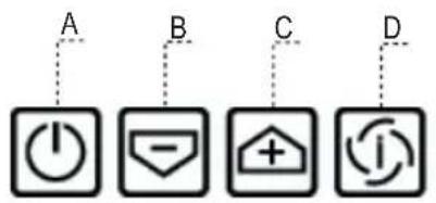
A B C D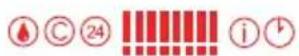
text_image
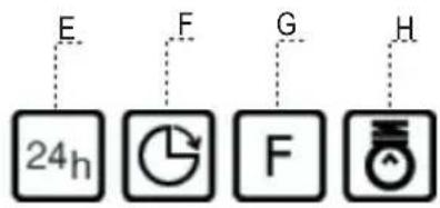
E F G H 24hControl panel
| Button | Function Display | |
| A Turns the suction motor on and off at the last speed used. | Displays the speed set. | |
| B Decreases the working speed. Decreases the lighted segments. | ||
| C Increases the working speed. Increases the lighted segments. | ||
| D Activates intensive speed from any other speed, including motor off. This speed is timed to run for 10 minutes, after which the system will return to the speed that was previously set. Suitable for dealing with severe cooking fumes. | I flashes and the segments on the Display are all lit.It is disabled by pressing the Button. | |
| E Starts the motor at a speed that allows a suction of 100 m^3/h for 10 minutes every hour, after which the motor stops. | Displays 24 and the segments on the Display, initially all lit, turn off one at a time in cycle.It is disabled by pressing the Button. | |
| F Activates automatic switch-off with a 30' delay. Suitable to complete elimination of residual odours. Can be activated from any position, it is deactivated by pressing the button of turning the motor off. | Displays a flashing Clock symbol.It is disabled by pressing the Button. | |
| G | Performs a Reset of the Filter saturation alarm when the button is pressed for approximately 2 seconds. | After 100 hours operation the Drop symbol is displayed to indicate saturation of the Metal Grease Filters.After 200 hours operation the letter C is displayed to indicate saturation of the Activated Charcoal Filters. |
| H Turns the Lighting System on and off. | ||
Keyboard Lock Command: it is possible to lock the keyboard, for example when cleaning the Glass, when the Hood Motor and Lights are turned off.
Press F (Delay) for approximately 5 seconds to enable or disable Keyboard Locking, which is always confirmed by a Beep and an animated signal on the display motor bar.
5 USEFUL HINTS
• To obtain the best performance it is advisable to switch 'ON' the cooker hood a few minutes (in the boost setting) before you start cooking and you should leave it running for approximately 15 minutes after finishing.
• IMPORTANT: NEVER DO FLAMBÉ COOKING UNDER THIS COOKER HOOD
- Do not leave frying pans unattended during use as over-heated fat and oil might catch fire.
- Do not leave naked flames under this cooker hood.
- Switch 'OFF' the electric and gas before removing pots and pans.
- Ensure heating areas on your hotplate are covered with pots and pans when using the hotplate and cooker hood simultaneously.
6 MAINTENANCE
Before carrying out any maintenance or cleaning isolate the cooker hood from the mains supply. The cooker hood must be kept clean; a build up of fat or grease can be a fire hazard.
Casing
- Wipe the cooker hood frequently with a clean cloth, which has been immersed in warm water containing a mild detergent and wrung out.
- Never use excessive amounts of water when cleaning particularly around the control panel.
- Never use scouring pads or abrasive cleaners.
• Always wear protective gloves when cleaning the cooker hood.
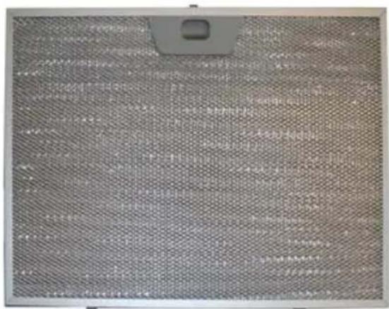
Metal Grease Filters
The metal grease filters absorb grease and dust during cooking to help keep the cooker hood clean inside. The grease filters should be cleaned once a month or more frequently if the hood is used for more than 3 hours per day.
To remove and replace the metal grease filters
- Remove the metal grease filters one at a time by releasing the catches on the filters; the filters can now be removed.
- The metal grease filters should be washed, by hand, in mild soapy water or in a dishwasher.
- Allow to dry before replacing.
Active Charcoal Filter
The charcoal filter cannot be cleaned. The filter should be replaced at least every three months or more frequently if the hood is used for more than three hours per day.
To remove and replace the filter
- Remove the metal grease filters.
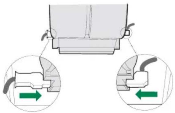
- Press against the two retaining clips, which hold the charcoal filter in place and this will allow the filter to drop down and be removed.
- Clean the surrounding area and metal grease filters as directed above.
- Insert the replacement filter and ensure the two retaining clips are correctly located.
- Replace the metal grease filters.
Extraction tube.
Check every 6 months that the dirty air is being extracted correctly. Comply with local rules and regulations with regard to the extraction of ventilated air.
Lighting.
If the lamp fails to function check to ensure it is fitted correctly into the holder. If lamp failure has occurred then it should be replaced with identical replacement.
Do not replace with any other type of lamp and do not fit a lamp with a higher rating.
7 GUARANTEE AND AFTER SALES SERVICE
- In the event of any malfunction or anomaly, notify your fitter who will have to check the appliance and its connection.
- In the event of damage to the mains supply cable, this can only be replaced by at approved repair centre appointed by the manufacturer who have the necessary tools and equipment to carry out any repairs properly. Repairs carried out by other persons will invalidate the guarantee.
- Use only genuine spare parts. Should these warnings fail to be observed it could affect the safety of your cooker hood.
- When ordering spare parts quote the model number and serial number written on the rating plate, which is found on the casing behind the grease filters inside the hood.
- Proof of purchase will be required when requesting service. Therefore, please have your receipt available when requesting service as this constitutes the date from which your guarantee commenced. This Guarantee does not cover :
- Damage or calls resulting from transportation, improper use or neglect, the replacement of any light bulbs or filters or removable parts of glass or plastic.
These items are considered to be consumable under the terms of this guarantee.
8 REMARKS
This appliance complies with European regulations on low voltages Directive 2006/95/CE on electrical safety, and with the following European regulations: Directive 2004/108/CE on electromagnetic compatibility and Directive 93/68 on EC marking.
When this crossed-out wheeled bin symbol ↗ is attached to a product it means the product is covered by the European directive 2002/96/EC. Your product is designed and manufactured with high quality materials and components, which can be recycled and reused. Please inform yourself about the local separate collection system for electrical and electronic product. Please act according to your local rules and do not dispose of your old products with your normal household waste. The correct disposal of your old product will help prevent potential negative consequences for the environment and human health.
text_image
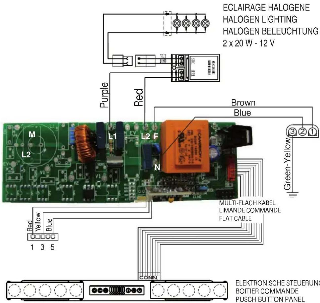
ECLAIRAGE HALOGENE HALOGEN LIGHTING HALOGEN BELEUCHTUNG 2 x 20 W - 12 V M L2 Red Purple Red Brown Blue Green-Yellow Multi-FLACH KABEL LIMANDE COMMANDE FLAT CABLE RED YELLOW Blue 1 3 5 CONN. ELEKTRONISCHE STEUERUNG BOITIER COMMANDE PUSCH BUTTON PANEL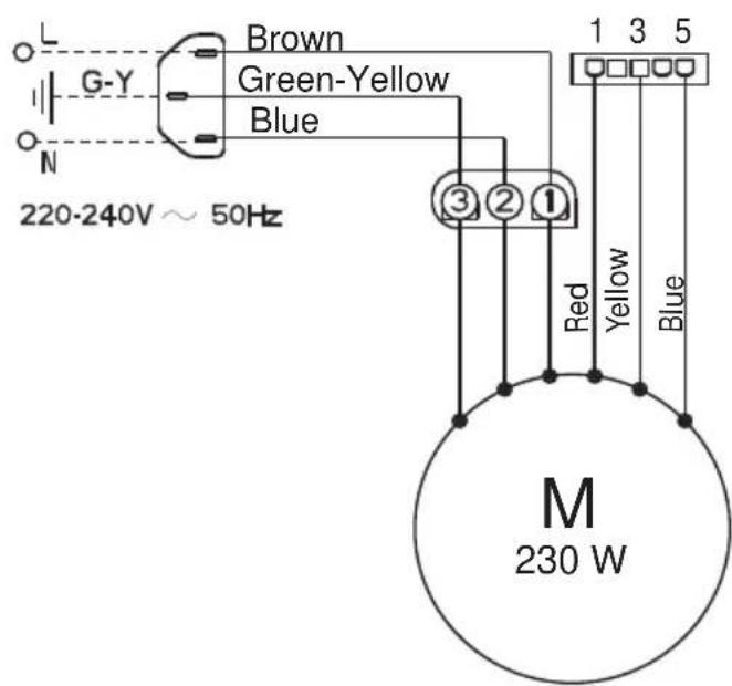
text_image
L G-Y Brown Green-Yellow Blue N 220-240V ~ 50Hz ③ ② ① Red Yellow Blue M 230 WA - AZUR - AZUR - AZUR BLAU
BK - BLACK - NOIR- SCHWARZ
B - BLUE - BLEU - BLAU
Br - BROWN - BRUN - BRAUN
G-Y - GREEN YELLOW - VERT JAUNE - GRÜN GELB
Gr - GREY - GRIS - GRAU
L B - LIGHT BLUE - BLEU CLAIR - HELL BLAU
P - PINK - ROSE - ROSA
V - PURPLE - MAUVE - MALVER FARBIG
R - RED - ROUGE - ROT
W - WHITE - BLANC - WEISS
W-P - WHITE PINK - BLANC ROSE - WEISS ROSA
Y - YELLOW - JAUNE - GELB
| Maj (Update) | Désignation |
| 120309 Vizio/2 Murale Verre depuis: Mars 2012 (from) | |
| Page | |
| 1/1 | 3S_Vizio_2_M_Verre_V2012-03 |
UK ELECTRICAL CONNECTION ELECTRICAL REQUIREMENTS
Any permanent electrical installation must comply with the latest I.E.E. Regulations and local Electricity Board regulations. For your own safety this should be undertaken by a qualified electrician e.g. your local Electricity Board, or a contractor who is on the roll of the National Inspection Council for Electrical Installation Contracting (NICEIC).
ELECTRICAL CONNECTION
Before connecting to the mains supply ensure that the mains voltage corresponds to the voltage on the rating plate inside the cooker hood.

text_image
BLUE (NEUTRAL) BROWN (LIVE) GREEN & YELLOW (EARTH)The wires in this mains lead are coloured in accordance with the following code: Green & Yellow Earth Blue Neutral Brown Live
As the colours of the wires in the mains lead of this appliance may not correspond with the coloured markings identifying the terminals in your connection unit, proceed as follows:-
This appliance is fitted with a 2 core mains cable and must be permanently connected to the electricity supply. The wire which is coloured blue must be connected via a double-pole switch having 3mm minimum contact gap on each pole. A Switched Fuse Connection Unit (EARTH) proceed as follows:
to BS.1363 Part 4, fitted with a 3 Amp fuse, is a The wire which is coloured brown must be connected recommended mains supply connection accessory to the terminal which is marked with the letter 'L' or ensure compliance with the Safety Requirements coloured red. applicable to fixed wiring instructions.
CH
natural_image
Exterior view of a modern stainless steel kitchen range hood with open vent (no signage or text visible)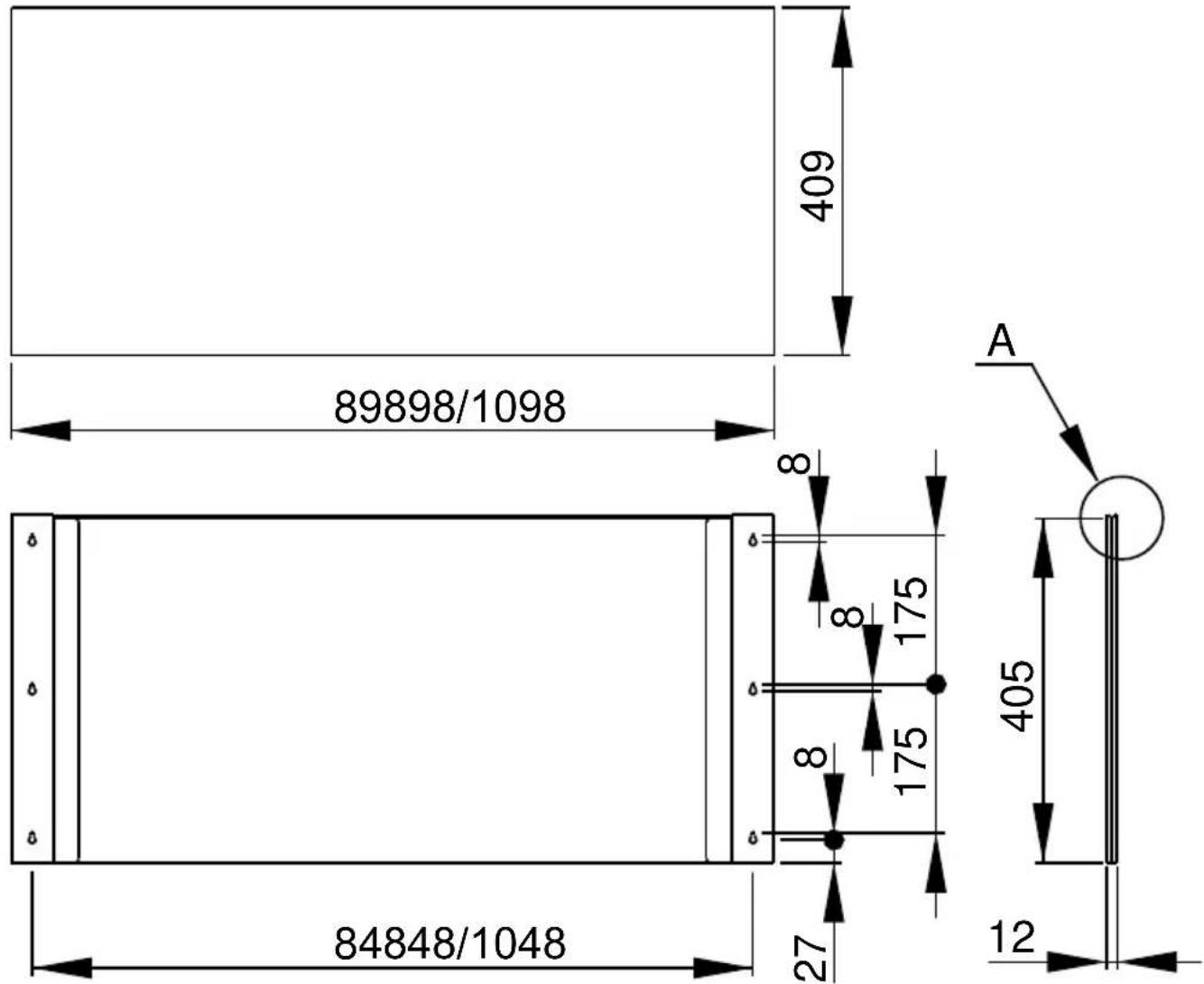
text_image
89898/1098 409 8 8 175 8 175 405 27 84848/1048 12 A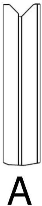
natural_image
Simple line drawing of a vertical V-shaped object with label A below (no text or symbols on the object itself)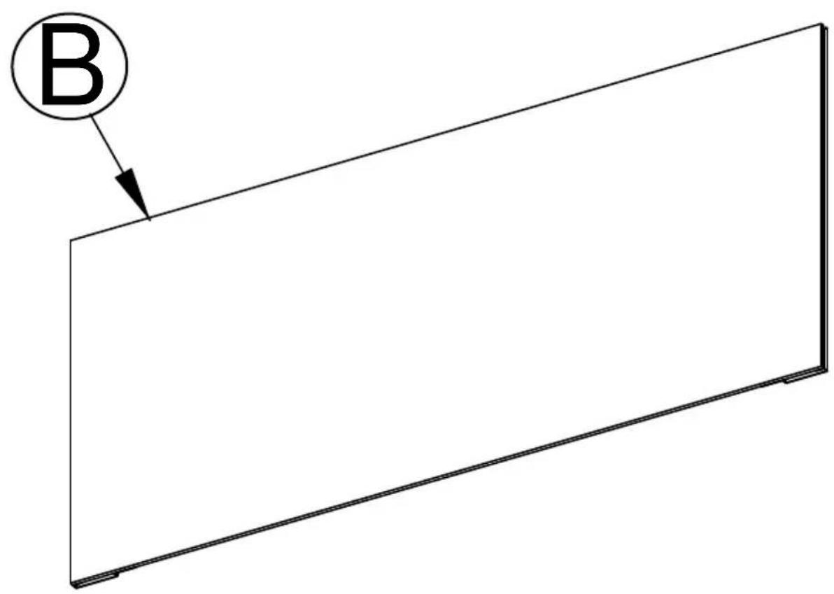
text_image
B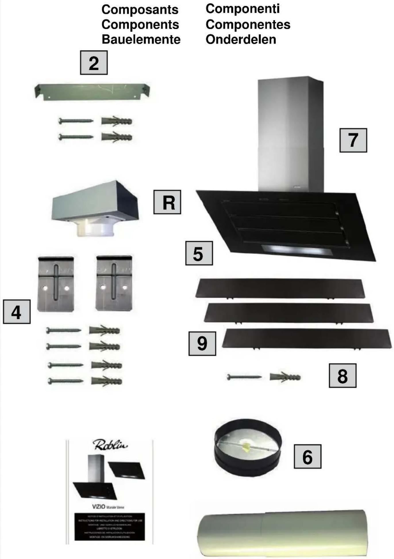
text_image
50 285 56 40 164 40 45° 400 35175175 Ø 170 113 293 40 Ø 6 260 200 670 H = 400 Ø 3 848 - 1048 ③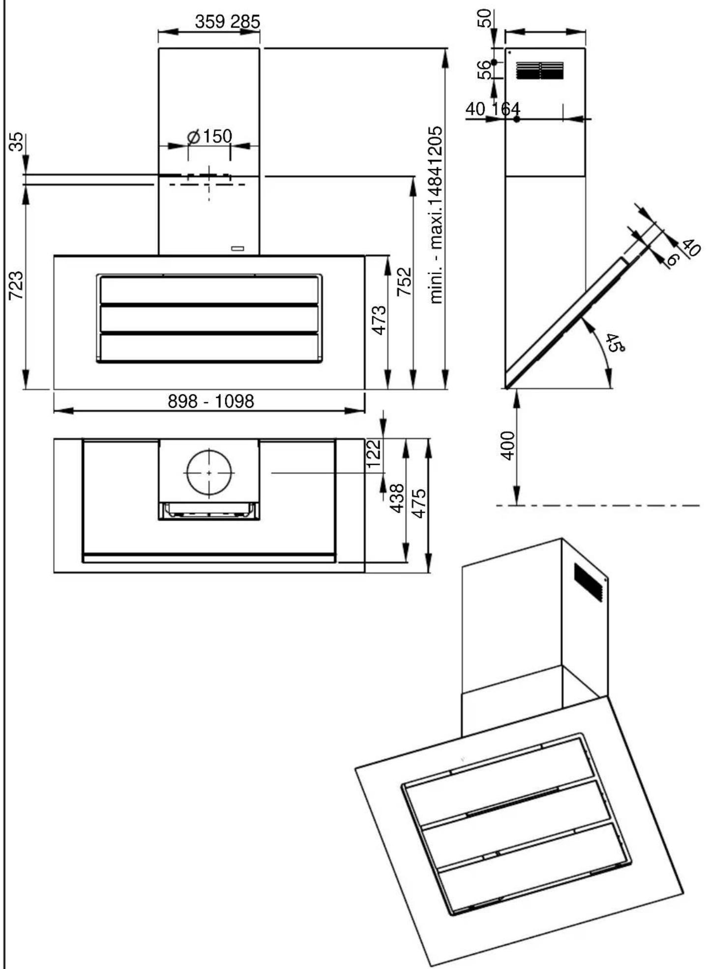
3
text_image
10 10 4 1070 260 304
text_image
Technical diagram showing a device with labeled components and a hand interacting with a green-labeled component, including a magnified view of the component.5
natural_image
Diagram showing mechanical assembly with two circular insets highlighting internal components (no text or symbols)6
text_image
R ø 150 6 ø 150 12c 7a 7bVIZIO 2 SMC
Composants
Components
Bauelemente
Componenti
Componentes
Onderdelen
natural_image
White plastic container with a circular top, no visible text or symbolsA1
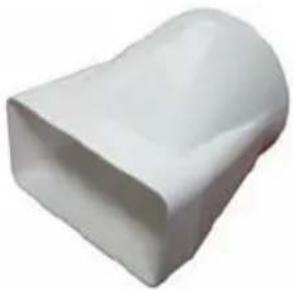
natural_image
White plastic object with smooth curved surface (no text or symbols)A2
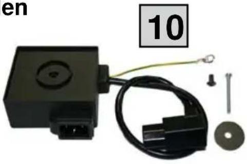
natural_image
Electronic component with black box, cable, and accessories (no visible text or symbols)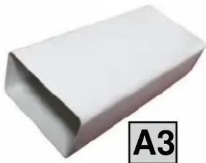
natural_image
White rectangular object with a label 'A3' in the corner (no other text or symbols)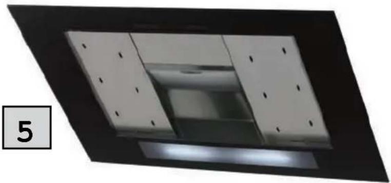
natural_image
Interior view of a ceiling-mounted room with recessed lighting and a central ventilation unit (no visible text or symbols)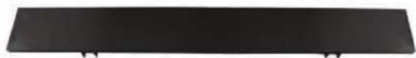
natural_image
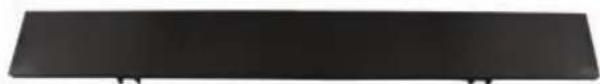
Solid black rectangular object with no visible text, symbols, or markings4
natural_image
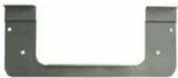
Metal bracket with two U-shaped cutouts and small holes, no text or symbols visible9
natural_image
Solid black rectangular object with no visible text, symbols, or markings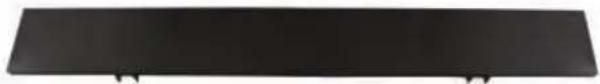
natural_image
Solid black rectangular object with two small protrusions at the bottom (no text or symbols)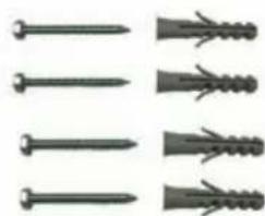
natural_image
Five different types of nail screw or screw, shown in separate row pairs (no text or symbols)
8
text_image
Roblin VIZIO Murale Vivre NOTICE: INSTALLATION AT PUBLICATION INSTRUCTIONS FOR INSTALLATION AND DIRECTIONS FOR USE PRODUCTIONS AND DESCRITICING LIMITED BY: DISTRUCION ADMINISITIONS OF INSTALLATION & PUBLICATIONS MOUNTAGE: EN DESCRITICING/LEADING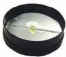
natural_image
Close-up of a petri dish containing a small yellowish object, possibly a gel or sample, with a thin rod extending from it (no visible text or symbols)6
natural_image
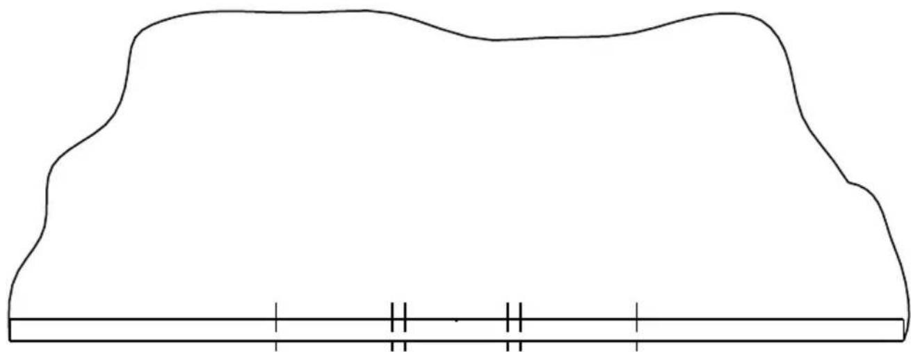
Simple line drawing of a curved shape with horizontal and vertical lines at the base (no text or symbols)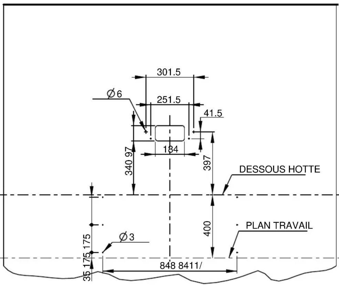
text_image
301.5 251.5 41.5 Ø6 340 97 184 397 DESSOUS HOTTE Ø3 400 PLAN TRAVAIL 35 175 175 35 175 175 848 8411/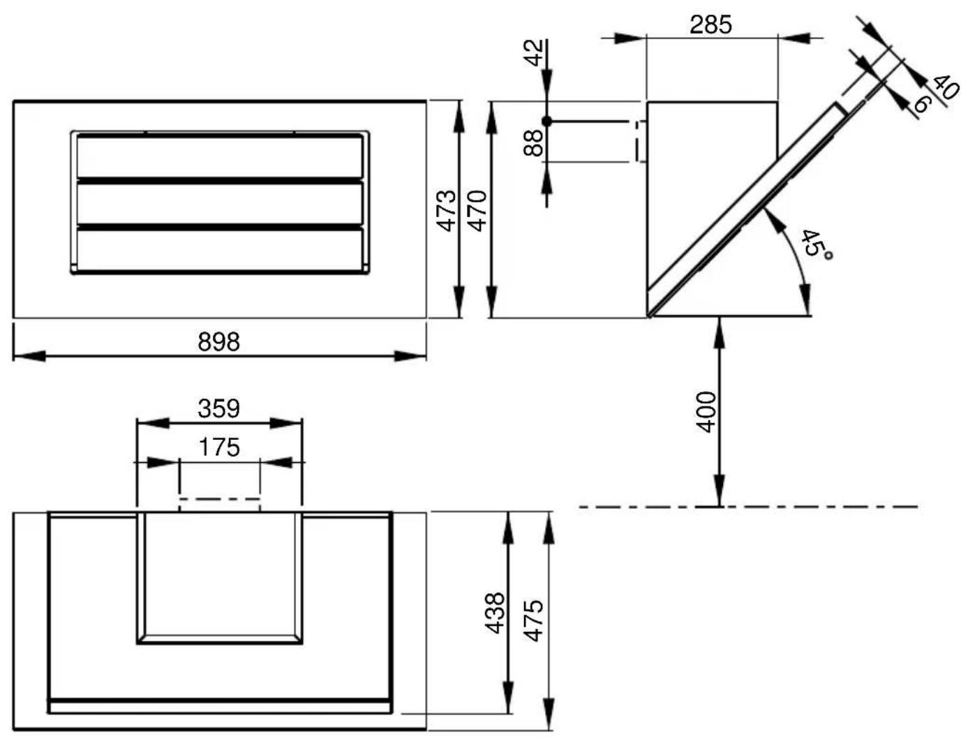
text_image
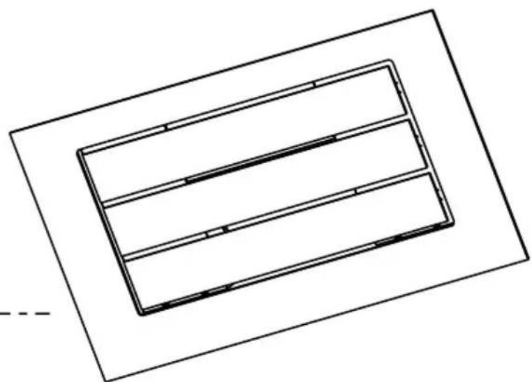
285 42 88 473 470 6 40 45° 898 359 175 400 438 475VIZIO 2 900 SMC
natural_image
Pure technical line drawing of nested rectangular components without any text, numbers, or symbols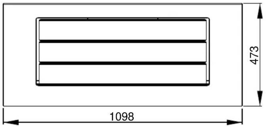
text_image
1098 473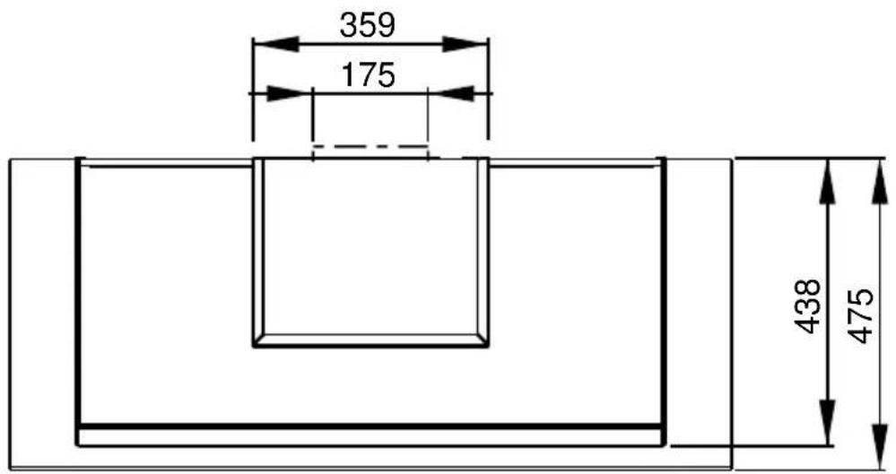
text_image
359 175 438 475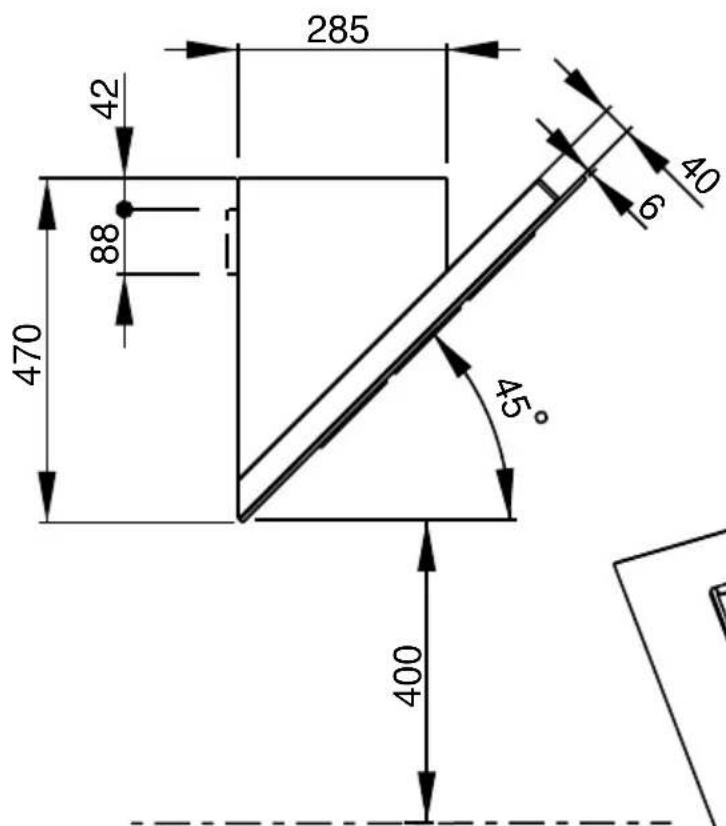
text_image
285 42 88 470 40 6 45° 400VIZIO 2 1100 SMC
natural_image
Pure technical line drawing of nested rectangular components without any text, numbers, or symbols7
text_image
301.5 251.5 397 400 4 3 ① ② ③ ④ ⑤ ⑥ ⑦ ⑧ ⑨8
text_image
Technical drawing of a mechanical assembly with dimension annotations and component labels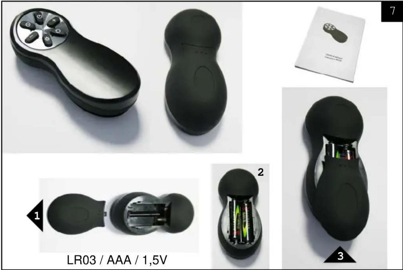
ACCESSOIRES ACCESSORI
ACCESSORIES ACCESORIA
ZUBEHÖRE ACCESSOIRES
natural_image
Black rectangular object with grid lines and small white protrusions at top (no visible text or symbols)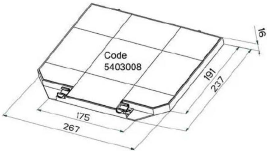
text_image
Code 5403008 191 237 175 267 16G4 12V 20W
text_image
Close-up of a mesh fan cover with printed text and a small logo, likely from a computer or electronics device.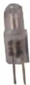
13MC070
323 × 262 × 8 mm
Rating plate of the cookerhood
natural_image
Pure mechanical diagram showing a beam supported by two supports with upward arrows indicating force or motion (no text or symbols)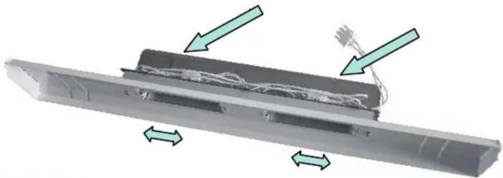
natural_image
Diagram of a mechanical component with arrows indicating direction, showing internal structure and assembly (no text or symbols)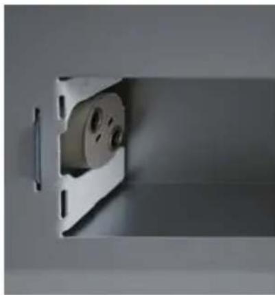
natural_image
Close-up of a white electrical outlet with a circular component, no visible text or symbols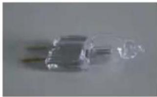
natural_image
Close-up of two transparent plastic electronic components with leads, no visible text or symbols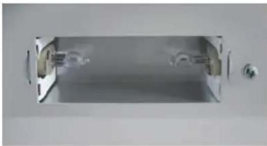
natural_image
Exterior view of a cylindrical mechanical component with mounting holes (no text or symbols visible)Fig. 9
Fig. 10
text_image
Technical diagram illustrating a mechanical assembly with labeled components and an inset image of a component.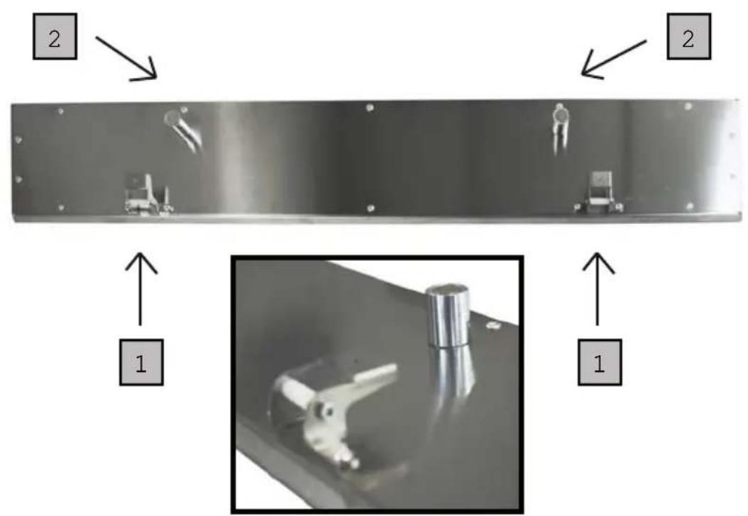
text_image
2 2 1 1text_image
Technical diagram showing steps to install a device with labeled components and wiring, including a 3D printing machine and a wire-wrapped unit.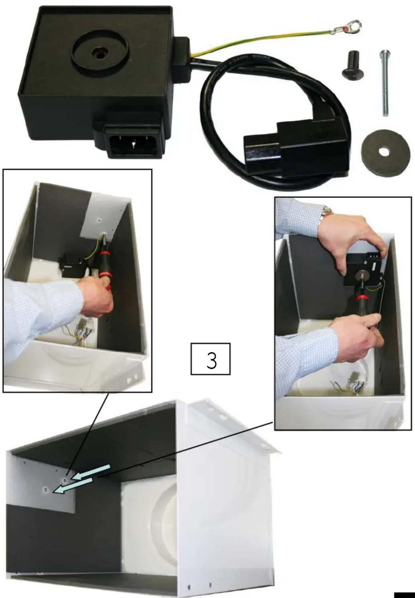
natural_image
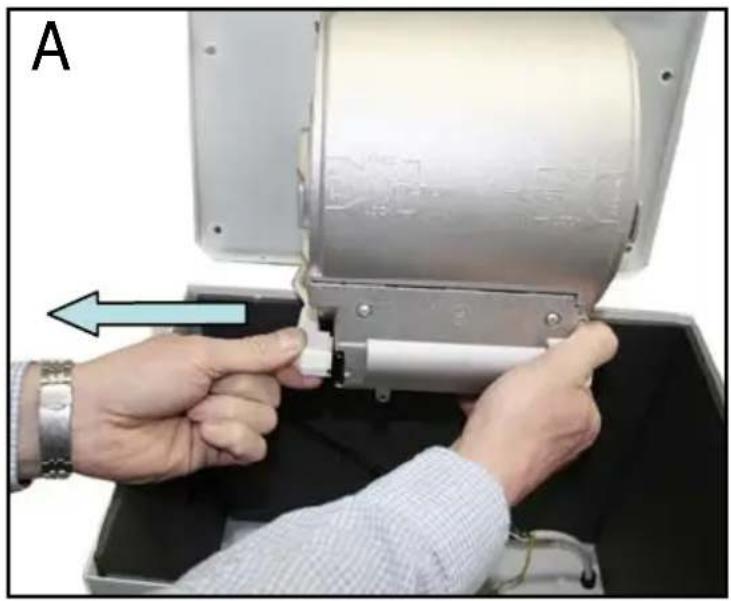
Close-up of hands installing a mechanical component into a device casing (no visible text or symbols)4
natural_image
Close-up of a person inserting a device into an open enclosure, with a blue arrow pointing to the component (no text or symbols visible)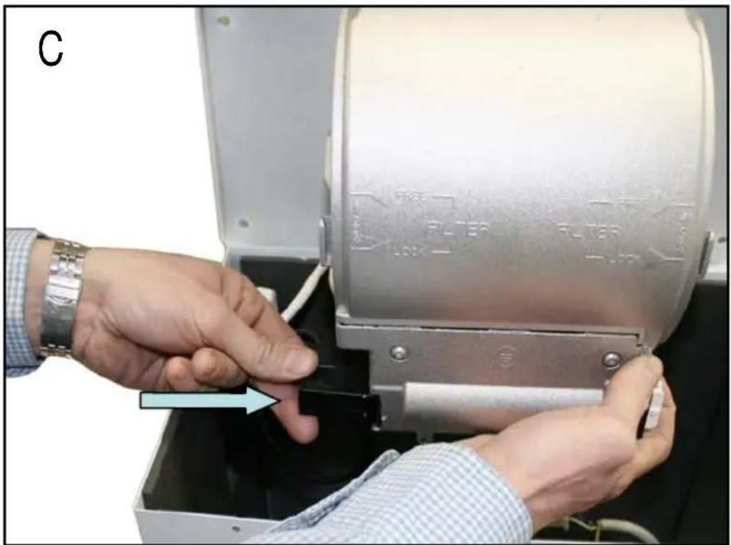
natural_image
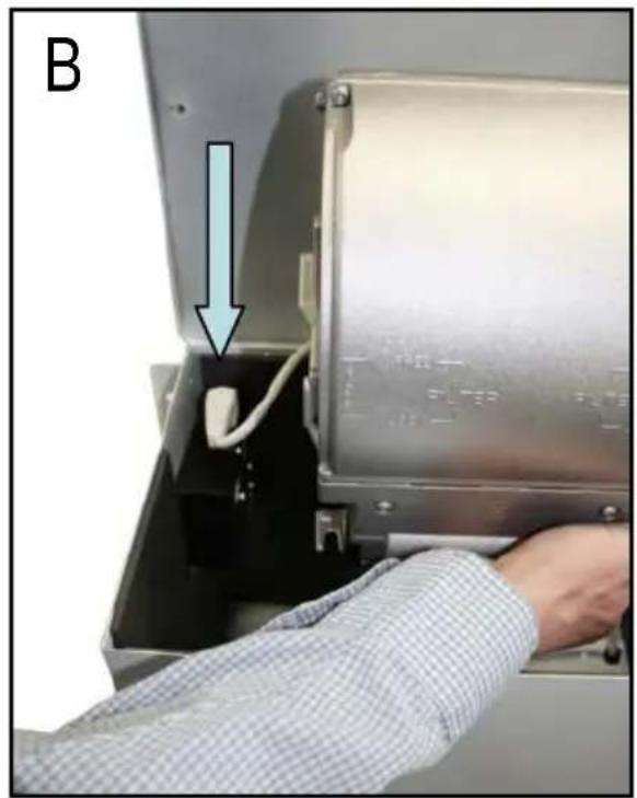
Close-up of hands operating a mechanical device with a blue arrow pointing to a component (no visible text or symbols)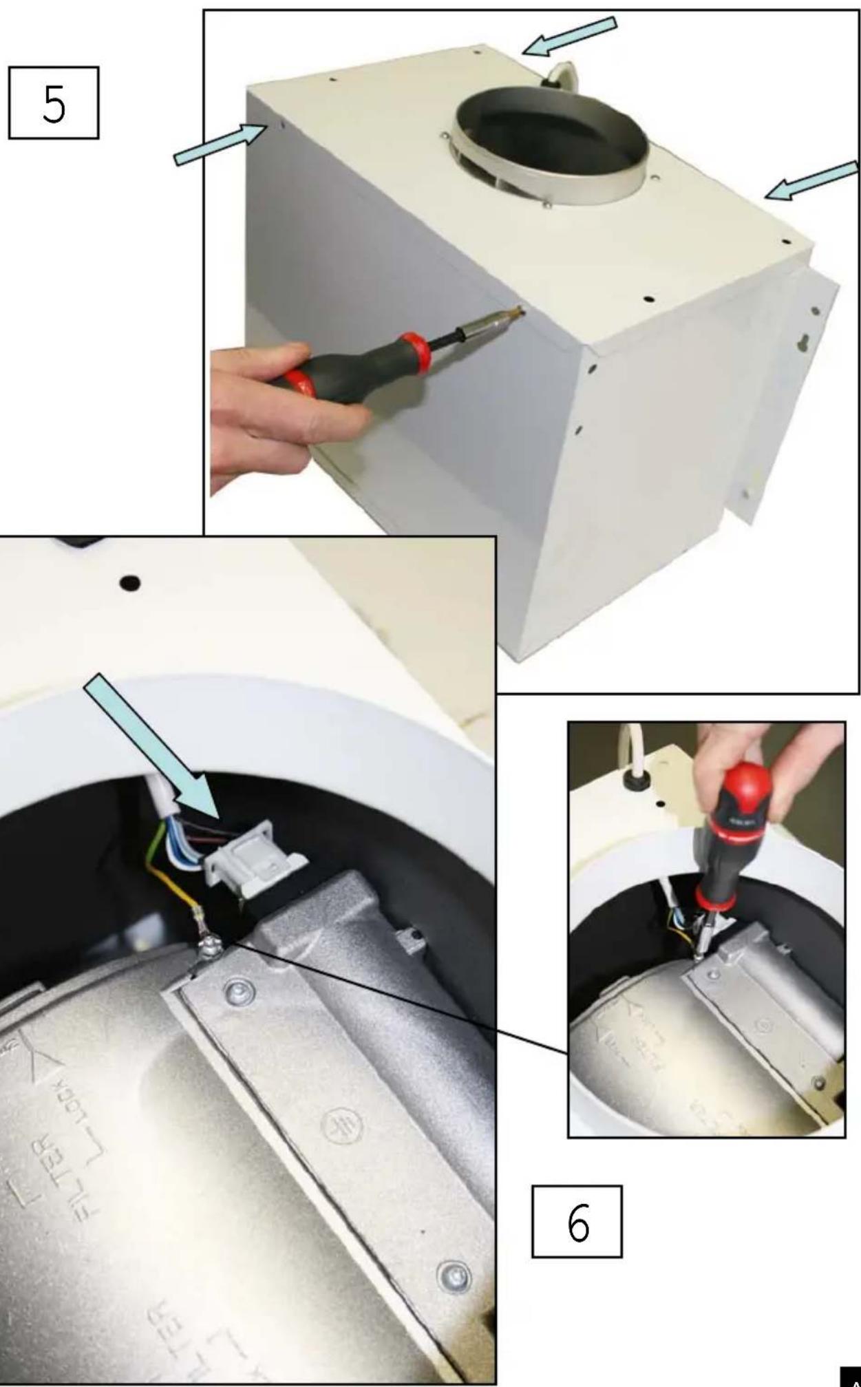
text_image
Close-up of a mechanical component with visible wiring and a blue arrow pointing to a cable or wire connection, labeled with part numbers and symbols.Roblin
FRANKE France S.A.S.