
Levado - Office FELLOWES - Free user manual and instructions
Find the device manual for free Levado FELLOWES in PDF.
| Product Type | Height-adjustable sit-stand desk |
| Brand | Fellowes |
| Model | Levado |
| Adjustable Width | 1219 to 1829 mm (48 to 72 in) |
| Standard Depth | 800 mm (31.5 in) |
| Power Supply | Main power cord |
| Maximum Weight Capacity | Not specified in the manual, refer to the product label |
| Main Functions | Motorized height adjustment, 4-position memory (2 users), LED display, system initialization |
| Control | Large button and M button for memory, left or right mounting |
| Feet | Folding with leveling glides |
| Materials | Steel frame, wood top (not specified, but standard) |
| Included Accessories | Base, brackets, headset (cable?), power cord, cable tray, cable management, Allen key, screws, bracket covers |
| Frame Warranty | 15 years |
| Electrical Components Warranty | 7 years |
| Intended Use | Indoor only |
| Care and Cleaning | Clean electrical components with a dry cloth. Unplug before cleaning. |
| Safety | Two people required for moving. Do not sit or stand on the desk. Keep children away. |
| Repairability | Do not disassemble the feet, control box, or controller. Contact after-sales service for any repairs. |
| Certifications | Compliant with WEEE directive |
Frequently Asked Questions - Levado FELLOWES
User questions about Levado FELLOWES
0 question about this device. Answer the ones you know or ask your own.
Ask a new question about this device
Download the instructions for your Office in PDF format for free! Find your manual Levado - FELLOWES and take your electronic device back in hand. On this page are published all the documents necessary for the use of your device. Levado by FELLOWES.
USER MANUAL Levado FELLOWES
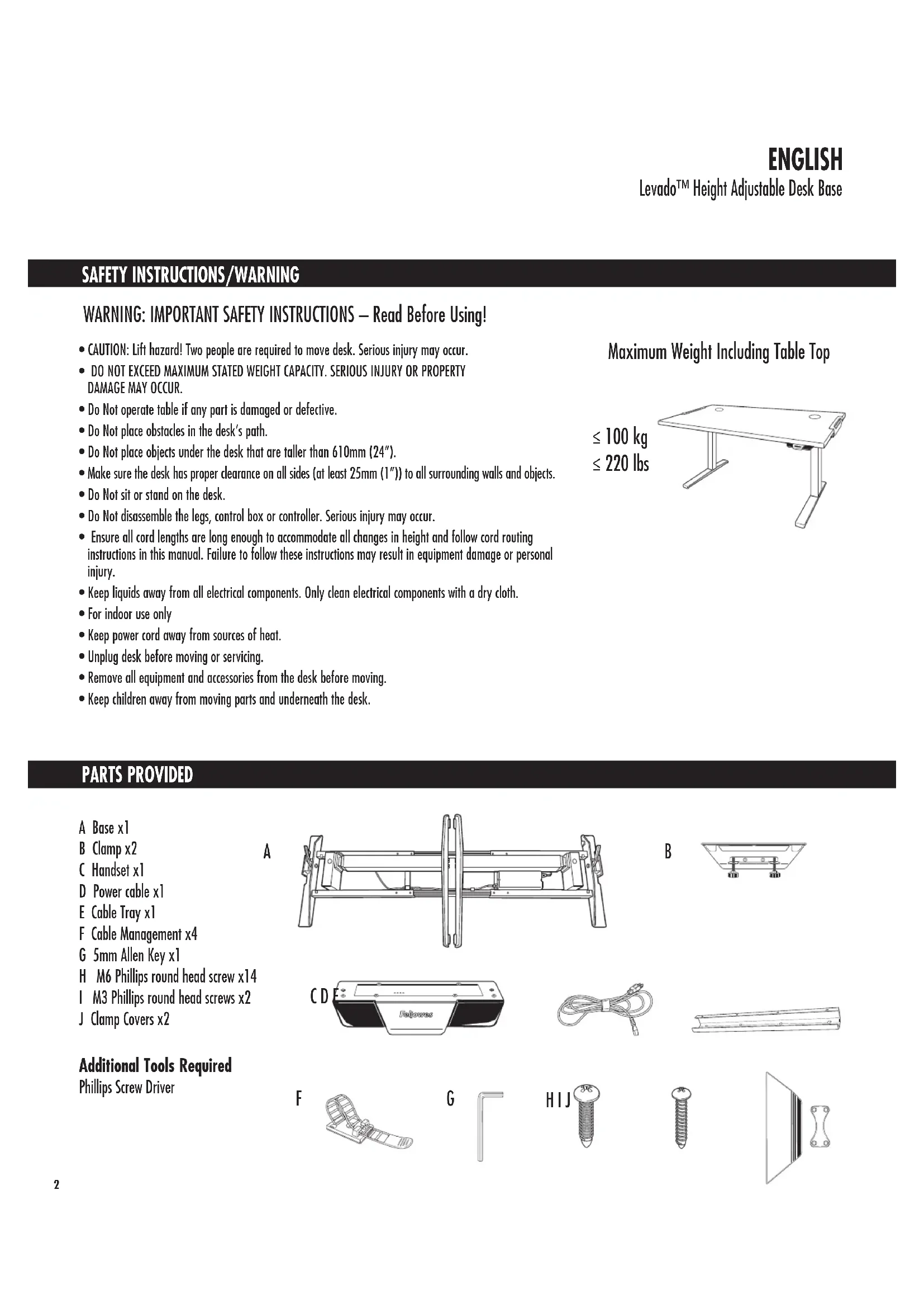
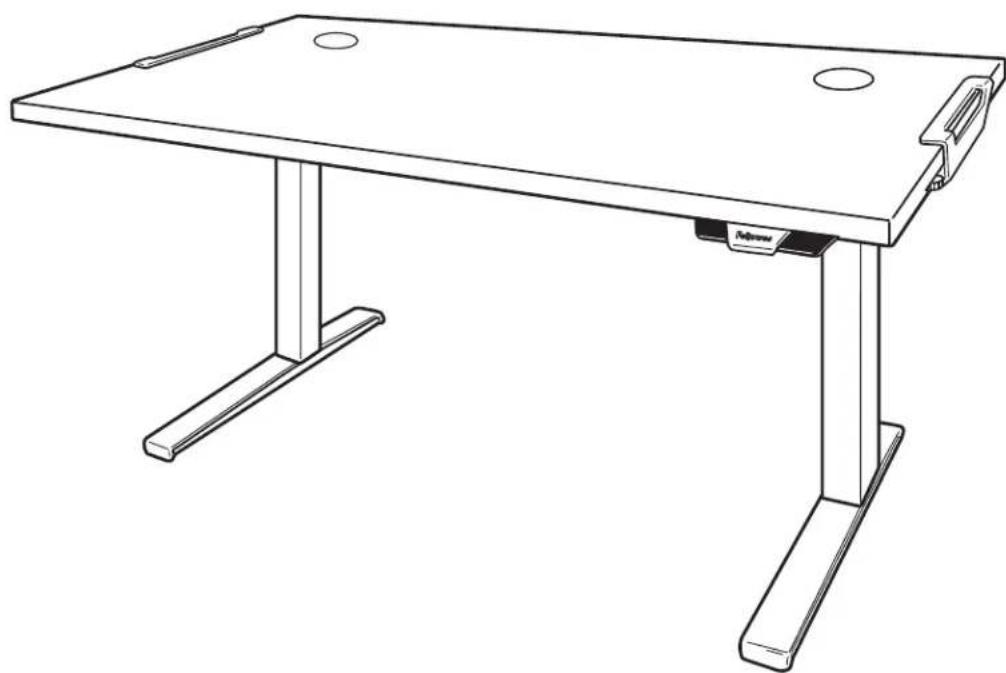
Levado™ Height Adjustable Desk Base
PLEASE READ INSTRUCTIONS BEFORE USE. DO NOT DISCARD.
LIRE LES INSTRUCTIONS AVANT UTILISATION. NE PAS JETER.
SAFETY INSTRUCTIONS/WARNING
WARNING: IMPORTANT SAFETY INSTRUCTIONS - Read Before Using!
- CAUTION: Lift hazard! Two people are required to move desk. Serious injury may occur.
- DO NOT EXCEED MAXIMUM STATED WEIGHT CAPACITY. SERIOUS INJURY OR PROPERTY DAMAGE MAY OCCUR.
- Do Not operate table if any part is damaged or defective.
- Do Not place obstacles in the desk's path.
- Do Not place objects under the desk that are taller than 610mm ( 24'' ).
- Make sure the desk has proper clearance on all sides (at least 25mm(1^ )) to all surrounding walls and objects.
- Do Not sit or stand on the desk.
- Do Not disassemble the legs, control box or controller. Serious injury may occur.
- Ensure all cord lengths are long enough to accommodate all changes in height and follow cord routing instructions in this manual. Failure to follow these instructions may result in equipment damage or personal injury.
- Keep liquids away from all electrical components. Only clean electrical components with a dry cloth.
- For indoor use only
- Keep power cord away from sources of heat.
- Unplug desk before moving or servicing.
- Remove all equipment and accessories from the desk before moving.
- Keep children away from moving parts and underneath the desk.
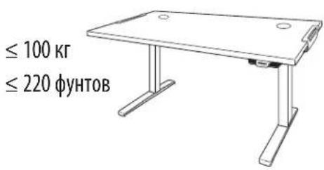
≤ 100kg ≤ 220 lbs
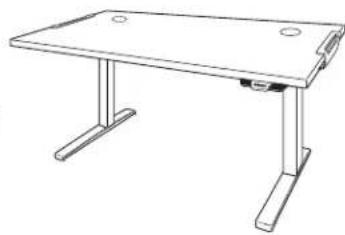
Maximum Weight Including Table Top
PARTS PROVIDED
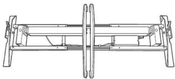
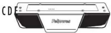
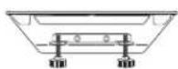
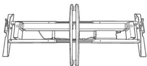
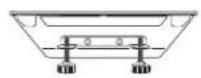
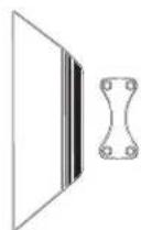
ABase x1
B Clamp x2
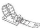
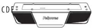
C Handset x1
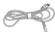
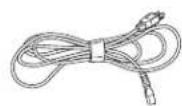
D Power cable x1
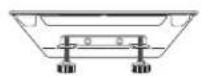
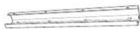
E Cable Tray x1
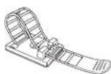
F Cable Management x4
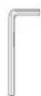
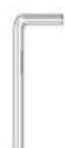
G 5mm Allen Key x1
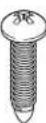
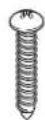
H M6 Phillips round head screw x14
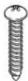
1 M3 Phillips round head screws x2
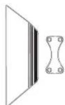
J Clamp Covers x2
Additional Tools Required
Phillips Screw Driver
A
B
F
G
HIJ

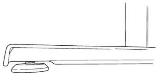
STEP1
Unboxing
- Open box from the top.
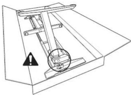
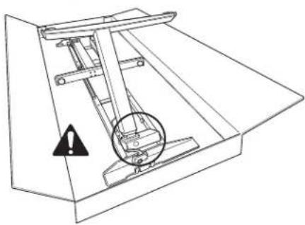
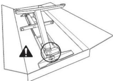
- Ensure levers on base are in the upright position.
- Fold out legs until they click. WARNING: Pinch Point! Keep hands and objects clear when lifting legs.
- Lock legs into place by pushing down on levers.
- Optional: If legs need to be folded, ensure lever is in the upright position and power is unplugged. Pull out pin and carefully guide legs to folded position.
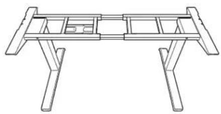
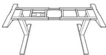
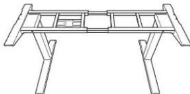
Using two people, flip the base upright. - The base arrives adjusted for 1600mm ( 63'' ) wide tables. If your table is not 1600mm ( 63'' ) wide you will need to adjust the base width 1219mm - 1829mm ( 48'' - 72'' ). See step 1B, otherwise move on to step 2.

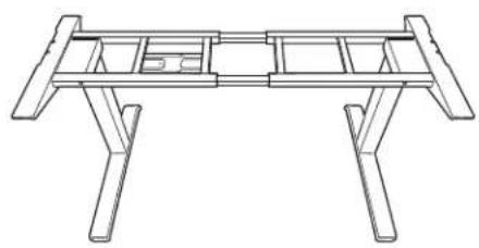
STEP 1B - Only required if table is not 1600mm (63") wide Adjust the cross channels to their final lengths
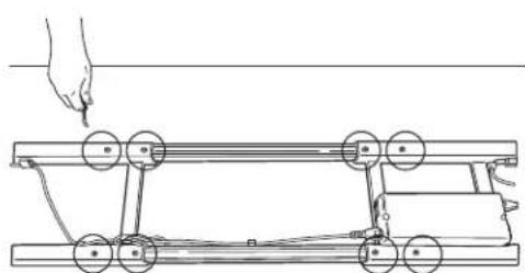
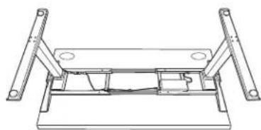
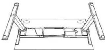
Using two people, place table face down on a soft, clean surface and place base on table.
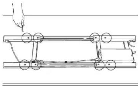
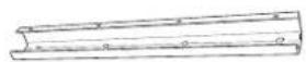
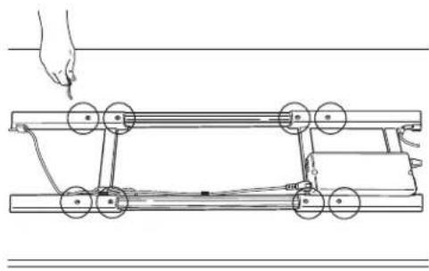
- Use the 5mm Allen key to loosen the (8) set screws on the inward side of the cross channels.
- Expand or contract the cross channels until flush with both ends of the desk. Free cables as necessary to allow the frame to adjust.
Once properly adjusted, use the 5mm Allen key to re-tighten the set screws (8 total).
Using two people, flip the base only upright.

STEP 2
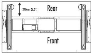
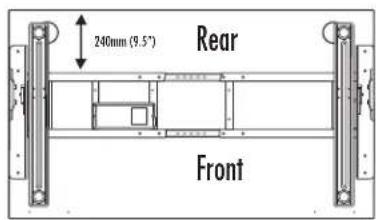
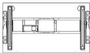
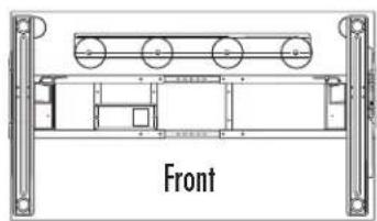
Adjust the position of the frame before attaching it to the table
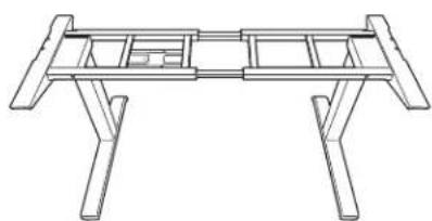
Using two people, place the table top on the base.
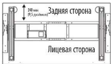
- Check that the table top supports on each side are flush to both ends of the desktop and align to the predrilled holes on the desktop
- The rear cross channel will be 240mm (9.5") for 800mm (31.5") Depth Tops from the rear of the table
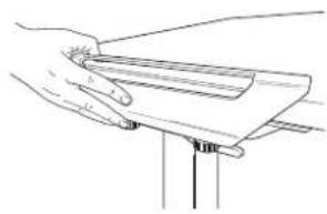
STEP 3
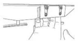
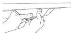
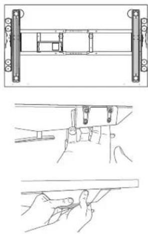
Clamping base to table
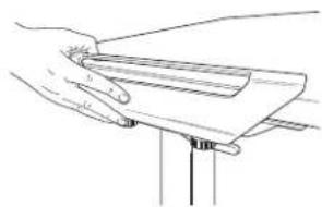
- Slide clamps on each side of the table.
- On each clamp, tighten the (2) thumb screws until each click.
INSTALL OPTION 2 - HARDWARE
STEP1
Preparing for installation using two people
- Place table face down on a soft, clean surface.
- Ensure levers on base are in the upright position.
- Fold out legs until they click, WARNING: Pinch Point! Keep hands and objects clear when lifting legs.
- Lock legs into place by pushing down on levers.
- Optional: If legs need to be folded, ensure lever is in upright position and power is unplugged. Pull out pin and carefully guide legs to folded position.
- Lift base out of box and place on table.
- The base arrives adjusted for 1600mm ( 63'' ) wide tables. If your table is not 1600mm ( 63'' ) wide you will need to adjust the base width 1219mm - 1829mm ( 48'' - 72'' ). See step 1B, otherwise move on to step 2.

STEP 1B - Only required if table is not 1600mm (63") wide
Adjust the cross channels to their final lengths
- Use the 5mm Allen key to loosen the (8) set screws on the inward side of the cross channels.
- Expand or contract the cross channels until flush with both ends of the desk. Free cables as necessary to allow the frame to adjust.
- Ensure proper alignment to predrilled holes on the desktop.
- Once properly adjusted, use the 5mm Allen key to re-tighten the set screws (8 total).
STEP 2
Adjust the position of the frame before attaching it to the table.
- Check that the top supports on each side are flush to both ends of the desktop and align to the predrilled holes on the desktop.
- The rear cross channel will be 240mm (9.5") for 800mm (31.5") Depth Tops from the rear of the table.
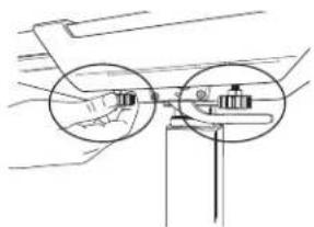
STEP 3
Attach base to the table
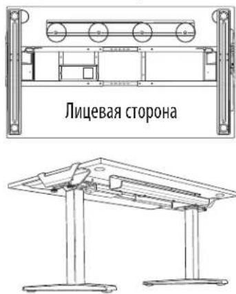
Use the M6 Phillips round head screws (10 total required) and a Phillips screwdriver.
- The screws fit through guides in the top of the supports and cross channel. Ensure proper alignment with predrilled holes on the desktop.
Using two people, flip the Base and Table upright.
- Attach clamp covers to each side. Start by placing the smaller piece on the inside of the clamp bracket. Align the larger piece and apply pressure to secure.
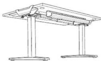
ACCESSORY INSTALLATION
STEP1
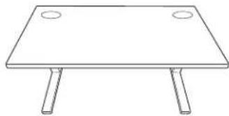
Cable Management
- Position the cable tray in the center of the table towards the rear and align with pre-drilled holes on the desktop.
- Attach the cable tray with (4) M6 Phillips round head screws. The open end should face the rear.
- Use the additional provided cable management as needed.
- Cables must not interfere with table operation.
- Cables must not interfere with the user.
Rear
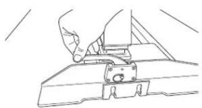
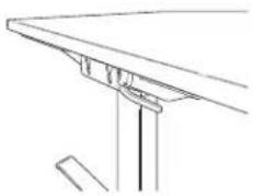
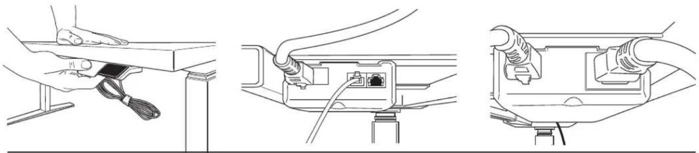
STEP2
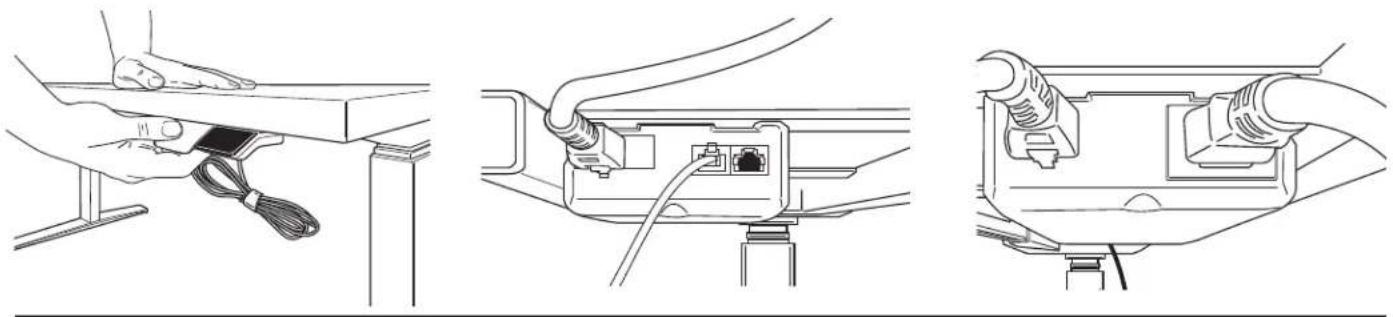
Attach the handset using the included adhesive strip or using two M3 Phillips round head screws
- Position the handset on the left or right side of the table, according to user preference.
- Mount the handset flush to the front edge of the table. If using M3 attachment method, ensure handset is lined up to pre-drilled holes on the desktop.
- Plug handset into controller on base.
- Plug power cable into controller on base and into an power outlet.
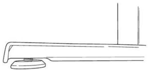
STEP 3
Level Feet
- If table feels unbalanced adjust the (4) leveling pads located on bottom of feet
- Turn clockwise to lower and counterclockwise to raise
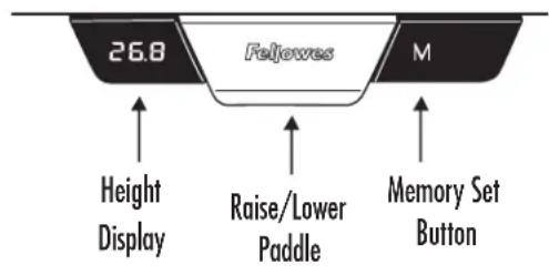
OPERATING INSTRUCTIONS
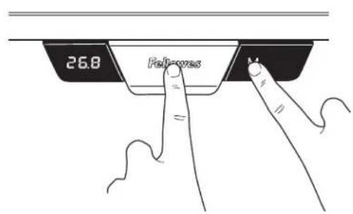
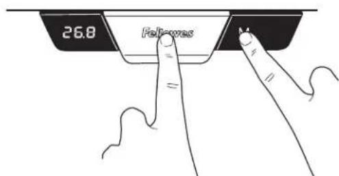
IMPORTANT: The initialization procedure below must be completed before operating the table. CAUTION: Ensure proper clearance. Make sure all objects are clear of the table
- Press and hold down the paddle and M buttons simultaneously for 10-15 seconds.
- The legs will begin to move down at half speed of normal operation.
- Continue to hold the buttons.
- The legs will move down to the lowest position, then rebound 2mm to 5mm (1/16" to 3/16") and stop.
- Release both buttons at the same time. This completes the initialization procedure.
If initialization is started and not finished, the table will not operate. You must finish the initialization process.
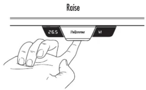
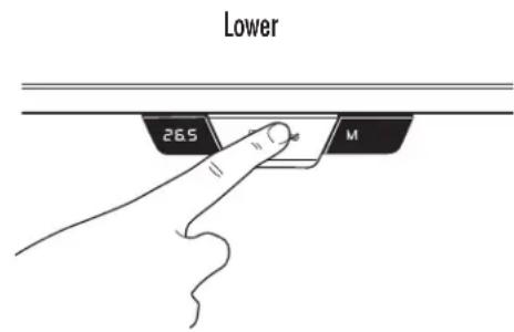
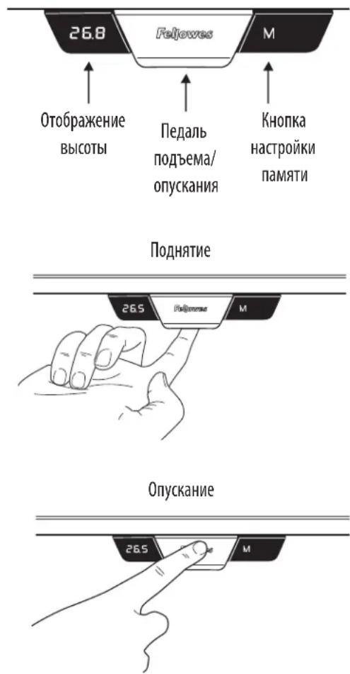
GENERAL OPERATION
Move the table up or down by pressing down or pulling up on the lever until the work surface reaches the desired height.
The table will continue to move up or down until you release the button or until the maximum or minimum height is reached.
MEMORY STOP POSITIONS
There are two groups of memory settings, each with two height settings. To toggle between the two users momentarily press the M button and display will read U1 or U2. Up to four memory stop positions can be used to save specific heights of the work surface. To set a specific position:
Raise or lower the table to the position you want to save.
Press and hold the M button for two seconds, the LED display will blink. This means it has stored the location. To clear storage settings, press and hold M button for 8 seconds until CLR displays.
CHANGING THE HEIGHT DISPLAY UNITS
This function allows you to toggle the display units from inches to centimeters.
Press and hold up and down at same time for 10 seconds.
RESET THE CONTROL UNIT TO FACTORY SETTINGS
Follow the same instructions to initialize the system.
FELLOWES LEVADOTM HEIGHT ADJUSTABLE DESK BASE LIMITED WARRANTY
Fellowes, Inc. (the "Company") warrants the Levado™ Height Adjustable Desk Base ("Product") to be free from defects in material and workmanship for the time period as set forth below.
The structural frame for a period of fifteen (15) years from the date of original purchase of the product.
All electrical components for a period of seven (7) years from the date of original purchase of the product.
This warranty applies only to the initial purchaser and does not cover claims resulting from misuse, failure to follow instructions on installation and use, neglect, use of unauthorized attachments, commercial use, use on a current or voltage other than specified on the product, or unauthorized service during the warranty period on conditions otherwise covered by warranty.
THE DURATION OF ANY IMPLIED WARRANTY, INCLUDING BUT NOT LIMITED TO ANY IMPLIED WARRANTY OF MERCHANTABILITY OR FITNESS FOR A PARTICULAR PURPOSE, IS EXPRESSLY LIMITED TO THE DURATION OF THIS LIMITED WARRANTY.
UNLESS REQUIRED BY APPLICABLE LAW, THE CUSTOMER'S EXCLUSIVE REMEDY FOR BREACH OF THIS WARRANTY OR ANY IMPLIED WARRANTY OR OF ANY OTHER OBLIGATION ARISING BY OPERATION OF LAW OR OTHERWISE SHALL BE LIMITED AS SPECIFIED HEREIN TO REPAIR, REPLACEMENT OR A REFUND OF THE PURCHASE PRICE, AT THE COMPANY'S SOLE OPTION.
UNDER NO CIRCUMSTANCE WILL THE COMPANY, ITS AFFILIATES, SUBSIDIARIES, RELATED ENTITIES, RESELLERS OR THEIR RESPECTIVE OFFICERS, DIRECTORS OR EMPLOYEES OR THOSE PERSONS FOR WHOM THEY ARE BY LAW RESPONSIBLE, BE LIABLE FOR CONSEQUENTIAL OR INCIDENTAL DAMAGES SUSTAINED IN CONNECTION WITH THE PRODUCT. THE COMPANY AND THESE OTHER PARTIES DO NOT ASSUME OR AUTHORIZE ANY REPRESENTATIVE OR OTHER PERSON TO ASSUME FOR ANY OF THEM ANY OBLIGATION OR LIABILITY OTHER THAN AS IS EXPRESSLY SET FORTH HEREIN.
The duration, terms and conditions of this warranty are valid worldwide, except where different limitations, restrictions or conditions may be required by local law.
Australia Residents Only:
Our goods come with guarantees that cannot be excluded under the Australian Consumer Law. You are entitled to a replacement or refund for a major failure and for compensation for any other reasonably foreseeable loss or damage. You are also entitled to have the goods repaired or replaced if the goods fail to be of acceptable quality and the failure does not amount to a major failure. The benefits under Fellowes' Warranty are in addition to other rights and remedies under a law in relation to the product.
CONSIGNES DE SECURITE/AVERTISSEMENT
m = 311
SCHRITT 1
Auspacken
INSTALLATIONSOPTION 2 - SCHRAUBEN
SCHRITT 1
VEILIGHEIDSINSTRUCTIES / WAARSCHUWINGEN:
MINNESLAGRADE STOPPLÄGEN
HCHPYKUINI NO TEXHNIKE 6E30NACHOCTN/NPEDYNPEXDEHNE
IPEyIeHHeB:BAKHbIE IPNABIIa TEXHnKbE30PiACHOCTN -IpoTuTe nepei nCnoJIb3oBaHneM!
BHIMAHHE:OnaCHO noHMMatb!ДЯп epemeueHna cToNa HuxHo 2 YenOBeka.Moxho nOlyuHTb cepbe3HyTO TpaBMy.
KIIATOPOPME 3AIPPELIAECTC IIPIWIAIATb MAKCMALIBHOE YKA3AHHOE YCNINE.3TO MOKET IPIPBECTN KTPABME NINIOBPEKDEHMOI3DEJIIM.
He nCnObnB3yIe CTOn, eCNi KaKaJ-Ni6o N3 cHaTeN NobpeXeHa Nm IMeET DeKeTbI.
Ha npTu CTOna He DonJxHo 6bItb nomEx.
- He cIeNyT nomeeaTb noT cTOn o6BeKtB bIwe 610 MM (24 JIOHa).
- Y6eIntecb, yTO CO Bcex CTOpOH CTOna eCTb Heo6xoJIMb3a3Op (He MeHee 25 MM (1 JIOm)) OT BCEx OKpykaioux CTEN IO6bektOB.
- He caaNTecb Hc TaHOBNTecb Hc CTON.
He pa36mpaiTe HOKKn, KOpO6Ky UnpaBnEHH Nm KOHTpONIeP. MoXHO nOJIyUHTb cepBe3HyTO TpaBMY.
- Y6eHNTecb, yTO DnHa Hhpya DOCTaTOUHa, YTO6bI COOTBETCTBOBaTb BCEM N3MeHEHm MByICOTb IN CNeDyTe HNCTpyKuIM No pOkoJaKe hUpya BToM pyKOBOCTBe. Heco6JIIOHeHne daHHbIX IHCTpyKcIM MoXET npMBECTN K NOBpeXdEHNIO OobpyoDaHn IITpABMaM.
KIOKCTb He OJINKa IOnaDaTb Ha 3JIeKTpuueCKNe KOMNoHEtbl. 3JIeKTpuueCKNe KOMIOHeHTbl MOxHO OuHAtb TOLko cyXoTpIKN.
- yctpoCTBO npedHa3aHcHNOI INCnOJIb3oBaHmI INCKLIHOITeJIbHO B 3aKpbItOM NOMEUHIM.
- Hpy ntaHn Cneyet depKaTb BdaH NTocTuHKnOB tenHa.
IpeepepeMeeeHemmnn06cnyKmbaHnEMOTKIOHTCTOJTOCTM.
-пелпелемшимубрпгсстлбсobopydobamиппнадlexhoctn.
-TeINdoJXHHbHaxoDHTBCNODaJIbWeOTDBNXUHXCACTeNHEoJXHHbHaxoDHTBCNODCTONOM.
MaKcImMaJIbHbI Bc, BKJIIOUaY CToneuHnUy
IPEyCMOTPEHHbIE DETAHN
A Ochobahme X1
B 3axumx2
C PAnenb ynpabneHn x1
D UHyp nHTaHaX1
E XeNo6 dIg Ka6eIg x1
F Ka6eJb-kaHai x4
G JIeCTnIRpaHbI 5 MM KInOuX1
H Bunt M6 Phillips c kpyrnoi roJOBKOx14
I BnHT M3 Phillips c Kpyrnoi roJOBKOx2
J Kpbiluka 3axima x2
Dpyrhe Heo6xOaMble HnCTpyMeHtbl
KpeTo06pa3Ha8OTBepTka
A
F
G
HIJ
B
WAR1
PacnaKobka
- OTKpoIte Kopo6ky Cbepxy.
y6eHntecb,yTO pbIaHa OCHOBaHH HAXOJrTcB B BepTKaJIbHOM IIOLOXeHHN. - BbItacknBaIte HoxKn Do uenUka. IPE PPEXDEHHe: Onachoe MeTo! Pn nOHaTmH OHXe CneIte 3a pykAmn N obBeKTam.
3aФИКСИРУТЕ HOЖКИ HA MeCTe, onyCTNB pbIuHr. - DononHnteBHO: Ecln HOxKn CneJeT c6paTb, To pbuar DoJXeH 6bItb HappaBHeN BBepx, a nHTaHHe CneJeT oKJIIOHTb. BbTaIuTe WmNBky u AKKypaTHo co6epNTe HOxKn.
-Дя NOBOPOA OCHOBAHNA,Notpe6yetcIЯ DA YeNoBnKa.
JaHHa 6a3o ymonuHIO OtperynpoBaHa Ira CTOnOB C uipHoi 1600 MM (63 JIOMa).Ean BaW CTOn Wnpe nn yKe,em 1600 MM (63 JIOMa),TO Bam Heo6xOIMo OTperynpoBaTb wnpHy oChOBaHna 1219 MM Do 1829 MM (OT 48 NIOMO Do 72 NIOMOB).CM. War 1B, B npotnbom cnuyae, nepexoJnte K wary 2.

KpeHHeHneOcHObI KCTOny
CdbnHbTe3aXkMbHaKaKdoCTopoHeCToIa.
HaKaJDOM3aXMMe3aTAHNTe(2)6apaKOBbIX BnHTaDIOUeNka.


BAPVAHT YCTAHOBKM 2 - O5OPYIDOBAHME
WAR1
IIOIroTOBka K yCTaHOBKe C npNBleHeHMe DByx IIODei
Pacnooxte cTOn IueBoN NOBepxHocTbIO BHN3 Ha MmKyo UcctyNOBepxHocTb.
- Y6eIntecb, cyo pbUarH Ha OCHOBaHm HaxOJaTcB B BePTuKaJIbHOM noIOKeHH.
BbTaUHTe HOxKn Do UeJyka. BHIMAHNE: OnacHoe MecTo! PpN IOHNATM HoxEK CJeINTe 3a pyKaMn N O6BeKtAm.
3aФИКСИРУТЕ HOЖКИ HA MeCTe, ONUCTN BpyaTn.
-Дононтельно:Есин HOЖКС cneJyET co6paTb,TO pbiHar DoJXeH 6bIb HAnpaBHeN BBepx,a NHTaHne cneJyET OTKJIIOuHTb.BbITauNTe WnINlbKy n aKKypaTHO cO6epnte HOXKn.
- BbItaunte OCHOBn Kopo6Kn N NOMeCTne Ha CTOneWNHcy.
JaHHa 6a3a no yMOnuHaHNo OTperyIuPObHa dNn CTOnOB C uHnHO 1600 MM (63 DIOHMa). Ecn Baw cTOn wNe Hn yXe, Yem 1600 MM (63 DIOHMa), To Bam Heo6xOIMo OTperyIuPObTa b WnpHy OCHOBHn oT 1219 MM Do 1829 MM (OT 48 DIOHMoD 72 DIOHMo). CM. Wa r 1B, B npotNBHom CNyae, nepexOJte K Wary 2.

WAT1B-Дястолов уcke nnn wne 1600 MM (63 IOIMa)
Otperynpyte nonepeHbke KaHaJIbI Do oKOHuaTehNo nnHbI
C nOmoIbIO WeCTnIRpaHHoro 5 MM KJIHOa Ocna6bTe 3aXIMHbIe BnHTbI (8) H BHyTpHeH CTOpOHe NonepeuHbIX KaHaNoB.
Pacunpbe mnn cy3bte kaHnbl 3anodnuc o c6eX cTOpOH cTOna. BbcboDnte Heo6xOIMyU nnHy Ka6enei nIpeynnpOBKn paMbI.
- y6eHntecb B BepHom paCnoNoXKeHn npEaBapNTeHbHO npocBepneHHbIX OTBepCTn Ha CTone.
- Pocne perynnpOBK nCOnb3yIe WecTurpaHHbI 5 MM KInOu, YTO6bI NOBTOPO3aTHyTB 3axmHbIE BnHTb (BCero 8 wT.).
WAR2
Otperynpyte noJooKeHne paMbI nepei npKpEnJIeHMe ee K cTony.
Y6eDntEcB, YTO CToKn CBepxHc TcPOhC ToLa paCNOJIOXHeHb Ha OOHOM KOHe CTOna H COBNaAdoT C npeBaPteNbHO pOcBepIeHHbIM OTBepCTHmHa CTOne.
3aHnI nonepuehBk KaHAN 6yET 240 MM (9,5 HIOMOB) Ha 800 MM (31,5HIOMa) rny6uHOn H 6yET pacnoaraTbca C3aHHe CTOPHOCTOla
WAR3
KpenneHnOCHOBaHnK cToJy
NcnoIb3yIte BnHTbM6 Phillips c kpyrIoo rOIOBko (Bcero 10 uT.) n OTBepKy Phillips.
BnhtbI DOnJXHbI npoTn no HappaBnaHOOM B BepxHeu qactn onop n no nonepeuHomy KaHaNy. Y6eNTecb B BepHom paCNoLoXeHHn PpeBapntbHo npocBepneHHbIX OTBePCTm Ha CTone.
-Дя nobobota ochobamru n ctola,notpe6yeTc da Yenobeka.
3akpenTe KpbIky 3axmHa KaXdoi CTOPOHe. HauHnTe c pa3MeueHnmeHbWe yactn Ha BHytpenHe CTopoHe 3axmHa. BbypOBnTe 6oJbSyIO Detalb HdaBnTe Ha Hee.
YCTAHOBKA AKCECCYAPOB
WAR1
Ka6eBbHbXeNo6
Pacnoonoxte KaebnbHbI XeNo6 nocepeHne 3aHHe CTOpOBbl CToNa M BbIpOBHaTe ee B COOTBeTCTBnC PpeBaPntbHo NpocBepHbIMN OTBepTnMn Ha CToJe.
3aKpEnTe XeNo6 (4) BuHTamM M6 Phillips c Kpyrnoi roNoBko. OTKpbTbI KOHeu DOnJKeH 6bItb HappaBJeHa 3aDHOU qAcTb.
- Pn Heo6xOJUMOCTM IcONb3yIte IOnOpHInTeJIbHbI JKeIo6 dJa Ka6eIa.
KaBEn He JIJIKHbI MeHaTb MCNoIb3OBAHnIO CTOnA.
Ka6eHn He doJXhbl MeaTaB nOb3oBaTeNo.
3aHnA CTOpOna
WAR2
PnKpEnne naHb ynpaBHeHna, nCnoB3y npnnaeMyo KneKyIO HeTy nn nCNoB3ya DBA BnTa c KpyIoo roIobKoi M3 Phillips
- NomeCTe Naenb ynpablenHn, Hn Ebyu nI npaByo CTOpOHy CToJa B COOTBeTCTBnC ppeNooyTeHnMaN NOB3OBaTeJ.
- Uctanobnte naHelb ynpabneHn, 3aNoDnIOHa nepeHem Kpae cTOna. NcnoB3yra MeoI KpenHeHMa M3 y6eInTeCb, YTO naHeb npabneHn, paonolaraetcBA COOTBeCTBmC npeBaPteNbHO pOcBepneHHbIMN OTBepCTnMn Ha cTone.
-Подклочипаньуnpавел,在ККНТролпepyHaOCHOBaHIM.
-Подкlioочешурпитаян К кOTponлелу Н OCHOBaHIMa 3aTeM Bpo3eTky.
WAT3
ypoBeHbHor
EcnBbOuyaete,TO cTOn HecbaanacnpoBaH,TO Otperynpyte (4) BblpaBHBnBAIOune onOpbl,pacnoNoKeHHbe B HnKHeuactn DnHa Hor
- NOBOPOT no yacoboi cTpeKe onyctnt cToI, a npotmb yacoboi cTpeKIN - NOHNIMET
PYKOBOJCTBO IIO 3KCIYYATAUIM
HNUUIN3AUINCCTEMBI
BAXHO:Процетура Инцаллзаши,првебеHHа HIXe,ДOLЖHa 6bIb 3aBepeHa nepeH NaHOM pa60Tb co CTolom.
BHIMAHHE:06ecneyteHaJIeXaIIN3a3Op.Y6eIITecb,TO BCE y6paHO cNoBepxHocTcTla.
Haxmnte u ydepkmbaTe neaBn KhoNky M B TeueHne 10-15 ckyHd.
Hoxknahynt onyckatbca co ckopoctbIO, B Da pa3a MeHbIe HopMaJIbHOH.
- PpOdoJkaTe yIepKnBaTb KHOJI.
HoxknccbnhycBn3 do caMoro HxKHeo noLoXeHna, 3aTeM otCKOuat Ha pacctoHne ot 2 MM do 5 MM (1/16 IIOMa do 3/16 IIOMa) n OCTaHOBATc.
- Otnyctnte 06e KhoiKnO ndHOBpeMeHHo.3To 3aBepuT npoueDpyu HnuaanHaauu.
Ecn HnHuaHnaHaHauTa, Ho He 3aKoHueHa, cTOn He 6yDet pa60TaB. Bbl DonxHbI 3abePHTb npouee CnHuaHnaH3aun.
OBUAR 3KCNPIYATAUIA
IpeMeCTNe CTOn BBepx HIN BHN3, Haxab NnN NOTAYB pbUar Do Tex nop, noka pa6oay NoBepxHOCTb He DOCTMHT XeJaEMO BbICOTbl.
CToI 6yJeT npoJOnKaTb DBnraTbCa BBepx IIN BHN3, NOKa Bbl He OTnyCTnte KhoNky INn NOka He 6yJeT IOCTnHyTa MaKcMaJIbHaA INM MmHMaJIbHaA BbICota.
NAMATb NIOJXEHNI
CyueCTBye TBe rpynnbHaCTpoek NaMnT, KaJdaI3 KOToPbIX XpaHIT DBe HaCTpOKn BbICOTbl. Ia nepeKIOUeHm MExdy DByMa NOnb3OBaTeJAMn HAXMMTE KHOINy M nHa 3KpaHe NoBHTcO603NaueHne U1 nn U2. MoKHO INcNoB3OBaTB Do Ytebipex CnoTOB NaMn DIn CoXpaHEnn NOXeHn BbICOTbl paOoey nobepxHOCTN. IInrTO, YTO6bl yTaHOBtB KOHKpeTHoe NOXeHne, BbINOHNTE cLeyOuee:
IOnHnMnTe mnn onyCTnTe cTOn do XeHaemOro nNoJoxHeHn.
HaKMTe u ydepXnBaTe KhoNky M B TeueHne 2 cekyH, 3aTeM LED-ekpan 6ydet MMrTaB. 3To 03hauaet, 4To OH coxpaHnI nnoXeHne. IJra TOrO, YTObIydaNTb HAcTPOkN, HaKMTe u ydepXnBaTe KhoNky M B TeueHne 8 cekyH, Noka Ha ekpaHe He noBtca coo6uHne CLR.
I3MEHEHNE EINHHU OTOBPAXKEHNy BbICOTy
C nOMOuBIO 30I OYHKUIN Bbl MOXeTe N3MeHATb eINHmCbI N3MepeHnR C IIOIMOB Ha caHTUMETpbI.
HaxmTe n noHnMmTe BBepx n onyCTe Bn3 n yapedknaBte B teeyne 10 ckyu.
CbPOCTb bIOK yIPABJIENHIO 3AOCKHX HACTPOEK
BbINOHNHe NcHcpyKuIN No HnHuaJIaN3aUIN CnCTeMbI.
OTPAHNUEHHA TAPAHNTN KOMTAHN FELLOWES HA PEYUNPYEMbI NIO BbICOTE CTOJI LEVADO
KomnaHf Fellowes, Inc. (Janaee «KomnaHnra») rapaHTmpyET, TTO perynmpyemb no Bbcote cTOn LevadoTM («M3denne») He 6ytet HmTe bdeektoB Maepnana n 3roToBneHnB TeueHne nepnoa BpeMeHn, yka3ahHoro HnKe.
CtpyKtpyHaa pama B TeueHne nTnHaaduTaH (15) net c daTb npBoHaayabHn noKynKn npOyKaT.
Bce 3eKtpueckMe aactn BteueHme cemn (7) nct C daTb npBnHoro npno6peTeHHn npOdykTa.
HaTcOaHraPantma PaCnPoCTpaHaeTc TOnbKa HApBHOaAaBHoro NOKyIaTeN Hpe PAcNoctPaHaeTc Ha nPeTeHm, Bo3HKUme B peYbTaHe npabInbHO rCNIOb3OBAHm, HecOIOeHm INcTpyKlmo No yCTAHObKe I NCIOJIb3OBAHm, He6pexHOrO INcIOJIb3OBAHm, INCIJIb3OBAHm CTOpOHmX KOMIIeKTyOuHX, KOMMEpeCKrO INcIOJIb3OBAHm, KcIOJIb3OBAHm pW HapJxHMe, OTNIHbIM OTyka3aHHO HA mDienM, MIn HeCAHQUHOHPOBaHHO OcbNyXbaHMa B TeueHne rapaHTmHO r cPoka Ha ycIOBX, Ha KOtOpbie paNpocTpaHaeTc rapaTm.
CPOK DECTBNIIO6bIX IOIOPA3YMEBAEMBXI TAPAHNTBI, BKIOUOARHO HE OPGAHUMBABCIIO6bIMNIOIOPA3YMEBAEMBMITAPAHTMNI TOBAPHOTOCOTHRMI INPINTIOHOCTIN DIA ONPEDELEHHON CEIN, YETKO OPGAHUECH CPOKOM DEIECTBNI DAHHbIX IAPAHNTHBXUCIOBN.
ECINI INHOE HE IPEINICAHO 3AKOHOM, NCKIIOHHTENIBHO CPEICTBO IPIPABOBIO 3AUNITbI POKYATNEIA B CIUYAE HAPYUHENDAHHbIX TAPAHTNIHBIX YCNOBIM INI IOPA3YMEBAEMbIX TAPAHINHBIX YCNOBIM, INIIOIIOXBIX DpyNX 053ATENBCTB, BYITEKAIOUHX IN3 DEICTBYIOE 3AKOHIOATENBCTBA, ORPAHINWAETCR YA3AHBBIM 3DECb IPIPABOM HA PEMOHT, 3AMEHY YCTPOCTBA WJIN KOMIEHCALWIO ETO NOKYIHON CTOMMOCTIN, HA YCMOTPENE KOMPAHIN.
KOMIIAHH, EE ΦIIMAIJIbI, IIOUPEHME, IAPTHEPCKME KOMIIAHM, IPOJABUcI bI NIX PNECTABNTEJI, PYKOBOCTBO M IIN COTPYHMK, A TAKKE JIMUA, KOTOPbIM OHN IIOOTHTBb IIO 3AKOHY, HN IPII KAKHX YCIIOBHX HE HECYT OTBETCTBEHHOCTN 3A BO3MEUHME YUCEPBA, CBZAHHO C 3KCIUYATAUIE EAHHO T3DEINIA. KOMIIAHN IN DYPTYE YIOMARHYtBe 3DECb CTPOHb HE YIOLHOMOUBAOT HNKAKNX CBOX X PDECTABNTEJIe IMIN DPYHX LIuC BPATb HA CE6B KAKME-JIN60 OB3ATEJIbCTBA IMIN OTBETCTBEHHOCTB, KPOME TEX, KOTOPbIE YETKO N3IOJEHb B DAHOM DOKUMHETE.
CpOKu ycnoBm dEeCTBm DaHHOI rapaHTm dEeCTBmTeBbHbI IaB BCEx CTpaH, KpOMeTex, B KoTOpBX 3aKoHOM HAIarAOTcN HbIe OpArHueHMa Y cNoBn.
TolboKoДЯЖИТЕЛ АСТРАПМ:
B COOTBCTBm C 3aKOHOM ABCTPANH O 3aUHTe npab nortep6ntela Hauu TOBapbI npdaTc H cHccknOuaemblm rapaHTMn. Bbl mMeete npab HO a3aMeHy mN BO3BpAT cpeCTB C cnYae kpyHNO HeCNPABHOCTn H a KaMNEHCauMIO 3a KaKME-10o dpyrne npdeCKaYEmble B pazymhix npedanx ybItknn NIO nobpeKeDnna. TaKke Bbl mMeete npab HO peMOHT nIN 3aMeHy TOba, eCNI TOBAP OKa3aJIc H enpHMeMeMoTO KauCTBa I tA HeCNPABHOCTb He cHTaTeC kpyHNO. BblObl no rapAHm KomNaHm Fellowes AByHOTc DOONHeHMe K dpyTM npabAM n cpeCTBaM npabOBn 3aUHTb B COOTBCTBm C 3aKOHODATEbCTBOM B OTHouEHm IN3dJIIn.
INSTRUÇÉS DE SEGURANÇA/ADVERTÊNCIA
ADVERTÉNCIA: INSTRUÇÉS DE SEGURANÇA IMPORTANTES — Leia antes de utilizes o aparelho!
Existem dos他们在 definir a few ways to define the definition of a group. Do you know how?
Eleve ou {? a mesa para a posicao que pretende guardar.
This product is classified as Electrical and Electronic Equipment. Should the time come for you to dispose of this product please ensure that you do so in accordance with the European Waste of Electrical and Electronic Equipment (WEEE) Directive and in compliance with local laws relating to this directive.
For more information on the WEEE Directive please visit www.fellowes.com/WEEE
French
Declaration of Conformity
Fellowes, Inc.
Unit 2 Ontario Drive, New Rossington, Doncaster, DN11 0BF, England declares that the product model Levado™ Height Adjustable Desk Base conforms with the requirements of the Low Voltage Directive (2014/35/EU), the Electromagnetic Compatibility Directive (2014/30/EU), the Restriction of Hazardous Substances Directive (2011/65/EU) and (2015/863/EU), the WEEE directive (2012/19/EU), the Eco Design Directive (2009/125/EC), and the below harmonized European EN Standards.
Mechanical Safety:
EN 527-1: 2011
EN 527-2: 2002
EN 527-3: 2003
Electrical Safety:
EN 60335-1:2017
EN 62233: 2008
EN 61558-1:2009
EN 61558-2-16: 2013
EMC:
EN 55014-1:2011
EN 55014-2: 2015
EN 61000-3-2: 2014
EN 61000-3-3:2013
ErP:
EN 50563:2011/A1:2013
Year Affixed: 18
Itasca, Illinois, USA
August 1, 2018

John Fellowes

- Levado™ Height Adjustable Desk Base
- SAFETY INSTRUCTIONS/WARNING
- WARNING: IMPORTANT SAFETY INSTRUCTIONS - Read Before Using!
- PARTS PROVIDED
- Additional Tools Required
- STEP1
- Unboxing
- STEP 1B - Only required if table is not 1600mm (63") wide Adjust the cross channels to their final lengths
- STEP 2
- STEP 3
- INSTALL OPTION 2 - HARDWARE
- STEP 1B - Only required if table is not 1600mm (63") wide
- ACCESSORY INSTALLATION
- STEP2
- OPERATING INSTRUCTIONS
- GENERAL OPERATION
- MEMORY STOP POSITIONS
- CHANGING THE HEIGHT DISPLAY UNITS
- RESET THE CONTROL UNIT TO FACTORY SETTINGS
- FELLOWES LEVADOTM HEIGHT ADJUSTABLE DESK BASE LIMITED WARRANTY
- CONSIGNES DE SECURITE/AVERTISSEMENT
- SCHRITT 1
- Auspacken
- INSTALLATIONSOPTION 2 - SCHRAUBEN
- VEILIGHEIDSINSTRUCTIES / WAARSCHUWINGEN:
- MINNESLAGRADE STOPPLÄGEN
- HCHPYKUINI NO TEXHNIKE 6E30NACHOCTN/NPEDYNPEXDEHNE
- IPEyCMOTPEHHbIE DETAHN
- WAR1
- BAPVAHT YCTAHOBKM 2 - O5OPYIDOBAHME
- WAT1B-Дястолов уcke nnn wne 1600 MM (63 IOIMa)
- WAR2
- WAR3
- YCTAHOBKA AKCECCYAPOB
- WAT3
- PYKOBOJCTBO IIO 3KCIYYATAUIM
- HNUUIN3AUINCCTEMBI
- OBUAR 3KCNPIYATAUIA
- NAMATb NIOJXEHNI
- I3MEHEHNE EINHHU OTOBPAXKEHNy BbICOTy
- CbPOCTb bIOK yIPABJIENHIO 3AOCKHX HACTPOEK
- OTPAHNUEHHA TAPAHNTN KOMTAHN FELLOWES HA PEYUNPYEMbI NIO BbICOTE CTOJI LEVADO
- INSTRUÇÉS DE SEGURANÇA/ADVERTÊNCIA
- ADVERTÉNCIA: INSTRUÇÉS DE SEGURANÇA IMPORTANTES — Leia antes de utilizes o aparelho!
- French
- Declaration of Conformity
Brand : FELLOWES
Model : Levado
Category : Office