
Lotus RT - Office FELLOWES - Free user manual and instructions
Find the device manual for free Lotus RT FELLOWES in PDF.
| Product Type | Sit-stand workstation with monitor arm |
| Brand | Fellowes |
| Model | Lotus RT |
| Desk dimensions (L x W) | Approximately 76 cm x 45 cm (estimated) |
| Compatible table thickness | 19 mm to 76 mm |
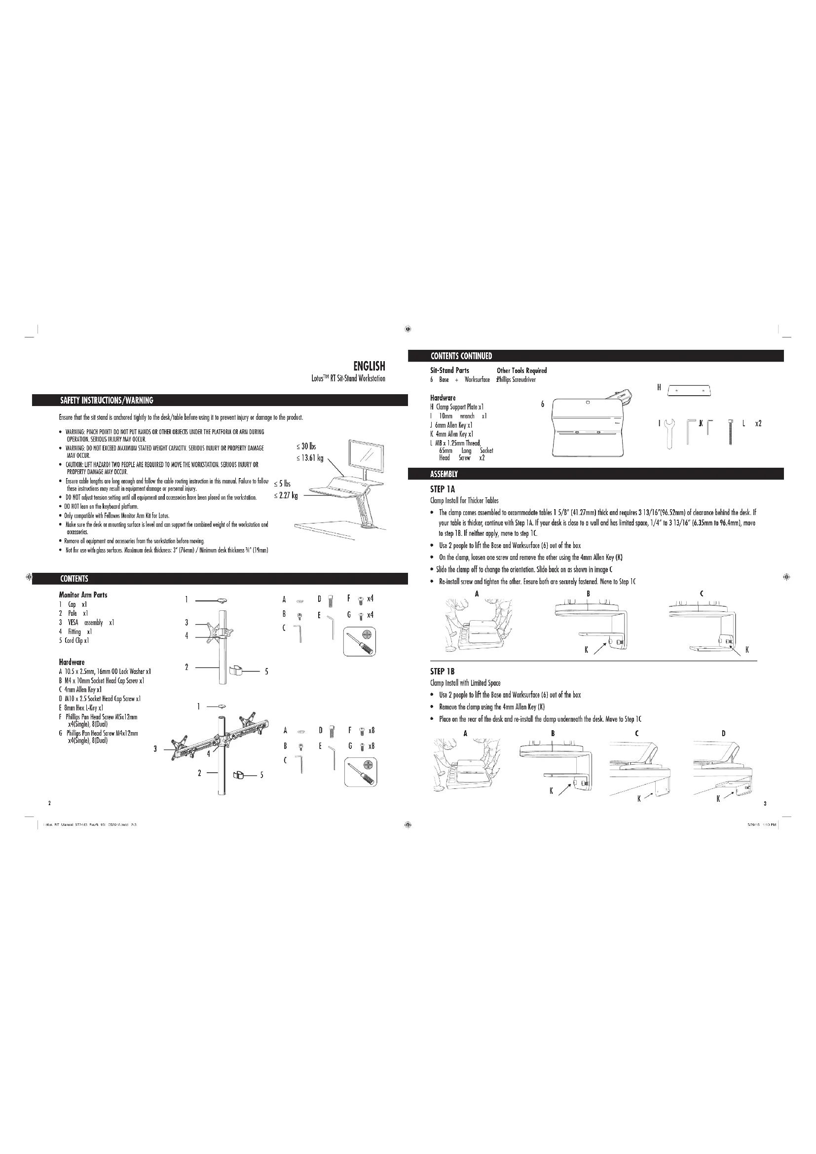
| Maximum load capacity | Approximately 25 kg (for dual monitor) |
| Material | Steel and plastic |
| Height adjustment | Yes, sit to stand |
| Lift mechanism | Gas with adjustable tension |
| Monitor arm included | Yes, compatible with single or dual monitor |
| VESA standard | 75 x 75 mm or 100 x 100 mm |
| Cable management | Yes, with cable pass-through and cable clip |
| Fixing clamps | C-clamp type for table |
| Tools required | Allen keys 4 mm, 6 mm, 8 mm, 10 mm, cross-head screwdriver |
| Warranty | 5 years limited |
| Cleaning and maintenance | Wipe with a damp cloth and mild detergent |
| Country of origin | China (estimated) |
| Repairability | Spare parts available from the manufacturer |
| Unit weight | Approximately 15 kg (estimated) |
| Number of monitors supported | Up to 2 |
Frequently Asked Questions - Lotus RT FELLOWES
User questions about Lotus RT FELLOWES
0 question about this device. Answer the ones you know or ask your own.
Ask a new question about this device
Download the instructions for your Office in PDF format for free! Find your manual Lotus RT - FELLOWES and take your electronic device back in hand. On this page are published all the documents necessary for the use of your device. Lotus RT by FELLOWES.
USER MANUAL Lotus RT FELLOWES
SAFETY INSTRUCTIONS/WARNING
Ensure that the sit stand is anchored tightly to the desk/ble before using it to prevent injury or damage to the product.
WARNING: PITCH POINTD DO NOT PUT HANDS OR BOTH OBJECTS UNDER THE PLATFORM OR ARM DURING OPERATION. SERIOUS LAIQUY MAY OCCUR.
- WARDING: DO NOT EXCEED MAXIMUM STATED WEIGHT CAPACITY. SERIOUS INJURY OR PROPERTY DAMAGE MAY OCCUR.
- CAUTION: LIFT HAZADI TWO PEOPLE ARE REQUIRED TO MOVE THE WORKSTATION. SERIOUS INJURY OR PROPERTY DAMAGE MAY OCCUR.
Ensure cable lengths are long enough and follow the cable routing instruction in this manual. Failure to these instructions may result in equipment damage or personal injury.
- DO NOT adjust tension setting until all equipment and accessories have been placed on the workstation.
DO HOT lea on the keyboard plstform
Only compatible with Fellowes Monitor Arm Kit for Lotus.
- Make sure the disk or mounting surfaces is level and can support the combined weight of the workstation and accessories.
- Remove all equipment and accessories from the workstation before moving.
Not for use with glass surfaces. Maximum desk thickness: 3^ (76mm)/Minimum desk thickness 忍 ^ 忍 [19mm]
CONTENTS
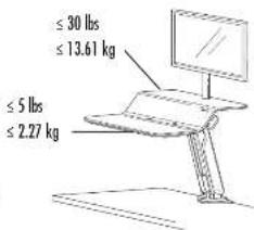
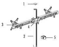
Monitor Arm Parts
1 Cx]
2 Pole x1
3 YES assembly x1
4Fittingx1
5 Cord Cap x1
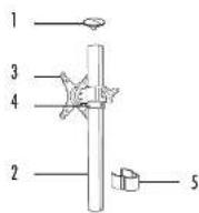
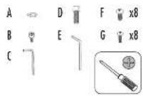
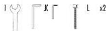
Hardware
A 10.5× 2.5mm 16 mm OD Lock Wosher x1
B M4 x 10mm Socket Head Cap Screw x1
C 4mm Allen Key x1
D MTO x 2.5 Socket Head Cap Screw x1
E 8mm Hex L-Key x1
F Phillips Pan Head Screw 5X1.2mm x4(Single) 8(Dual)
G Phillips Pan X Hand Screw 4X12mm x4(Single) ,B(Dual)
CONTENTS CONTINUED
Sir-Stend Parts
6 Base + Ws
Hardware
H Clamp Support Plate x1
1 10mm wrench x1
1.6mm idlen Xeyxl
4mm Allen Key x)
1. AB× 1.25mm Thread
65mm Long Socket
Head Screw
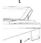
ASSEMBLY
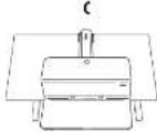
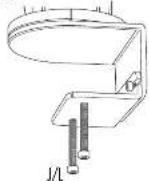
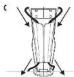
Clamp Install for Thicker Tables
- The clamp comes assembled to accommodate tubles 1 / 58^ (41.27mm) thick and requires 3 13/16" (96.52mm) of clearance behind the desk. If your table is thicker, continue with Step 1A. If your desk is close to a wall and has limited space, 1/4" to 3 13/16" (6.35mm to 96.4mm), move to step 1B. If neither apply, move to step 1C.
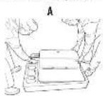
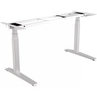
Use 2 people to lift the Base and Worksurface (6) out of the box
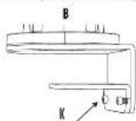
On the clamp, loasn one screw and remove the other using the 4mm Allen Key (K) - Slide the clamp off to change the orientation. Slide back on us shown in image C
- Re-install screw and tighten the other. Ensure both are securely fastened. Move to Step 1C

STEP18
Clomp Install with Limited Space
Use 2 people to lift the Base and Worksurface (6) out of the box
- Remove the clamp using the 4mm Allen Key (K)
- Place on the rear of the desk and re-install the clamp underneath the desk. Move to Step 1C
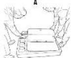
STEP1C
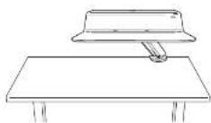
Unbox and determine sitting home position
Use 2 people to lift the Bose and Worksurface (6) out of the box
- Slide the Base and Worksurface (6) onto the table
Determine your desired sitting home position Note: If your desired sitting position is in the center of the table, choose a starting position that is offset from the center [image 0]
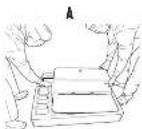

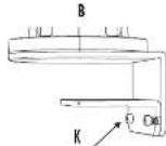
STEP2
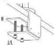
Clomp
Insert two M8 screws [L] into the Clomp
- Place the Clamp Support Plate (H) on top of the M8 screws (L). Ensure the tip of the screws align to the holes on the Clamp Support Plate (H)
- Tighten the M8 screws (L) with the 6mm Allen Key (U) until the Clamp Support Plate (H) is secured to the desk
A
B
STEP3
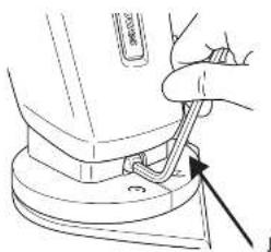
Raise sit-stand
- Remove the zip tie from the lever on the right side of the platform
- Engage the lever and raise the sit-stand
- (Optional) If you'd like the lever on the left side of the platform, remove the (2) M6x10mm bolts holding the handle with the 4mm Allen Key (K). Re-attach to the left side
A
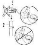
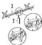
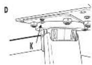
STEP 4A
Attach Monitor Arm
Install Monitor Pole (2) by placing into cutout on platform and inserting M10 screw (D) with lock washer (A) through the underside of the platform
- Tighten the M10 screw (D) using 8mm Hex L-Key (E)
- Engage the lever and lower the worksurface to the desk.
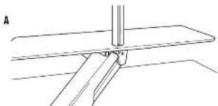
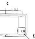
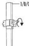
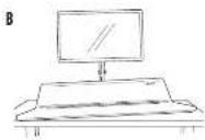
STEP4B
Attach Monitor Arm
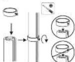
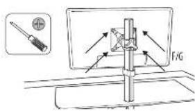
- Attach the Fitting (4) to the Monitor Pole and tighten using a Phillips screw driver when at the desired height (Image A).
- Slide the YESA assembly onto the Monitor Pole (2) and tighten using the knob on the rear (images B/C).
- Insert cap onto top of pole and secure using M4 screw (B) and 4mm Allen Key (C)
A
B
C
Single Monitor Arm Dual Monitor arm
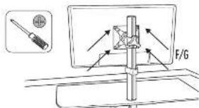
STEP5
Amoch (Monitor)
attach your monitor; to the VESA assembly using the included Philips Pon Head Screws M5x1.2mm [F] or M4x 1.2mm [G], depending on your monitor
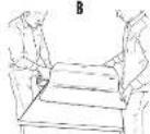
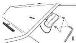
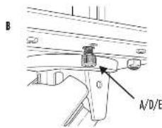
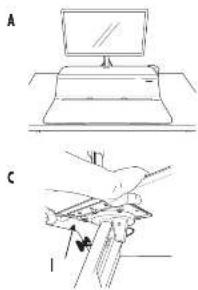
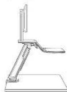
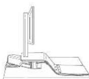
STEP 6 (Optional)
Adjust Platform Level
Activate lever and move unit to desired home sitting position (imoge A)
- The worksurface is assembled to be level, however certain setups may show lifting of the corners (image B). In order to adjust, follow the steps below
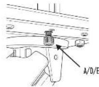
Determine if the left or right side is lifting up
- Engage the lever and raise the worksurface
- Opposite to the side which is raised, loosen the (2) N6 nuts on the underside of the platform using the 10mm wrench (1)
- On the some side, lighten the M4 adjustment screw (imoge D) using the 4MNI Allen Key (KI until the work surface is level
Re-lighten the two 16 nuts
Lower the worksurface back to the home sitting position. If not to the desired setting, repeat steps above until flush
STEP7
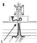
Cord Management
- Ensure your workstation is raised to the highest position
- Route your keyboard and mouse cords through the holes in the worksurface
- Route your monitor cards down the pole and clip with included card clip (5)
- Continue routing monitor cords down through the card funnel at the rear of the platform
- Gother all cords underneath platform and route through the arm to the base
- Ensure proper cord length for desired range of motion

STEP8
Tension Adjustment
Adjustable tension makes it effortless to raise and lower your sit-stand Start by raising the sit-stand to the highest position with all equipment and accessories placed on the workstation.
- Lotus RT is shipped at the lightest tension setting. Turn the ball located at the rear of the base counter clockwise using the 6mm Allen Key [2] to offset heavier weights. As a guideline, approximately 10 half turns are needed to offset a single monitor setup, 25 half turns for a dual monitor setup. The exact number of rotations depends on your personal comfort. Once you have properly adjusted the Lotus RT, it should feel effortless to raise and lower.
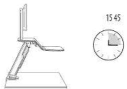
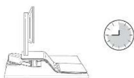
RECOMMENDED USAGE
Start by standing for 15 minutes each hour. Adjust based on what is comfortable for you.


FELLOWES LOTUS™ RT SIT-STAND WORKSTATION 5-YEAR LIMITED WARRANTY
Fellows, Inc. (the "Company") warrants this product to be free from defects in material and workmanship appearing within five (5) years from the date of the original purchase of the product. If such a defect appears during the warranty period, the Company will (at its sole option) either repair or replace the defective product with no charge for shipping or parts or refuel the purchase price.
This warranty applies only to the initial retail purchaser and does not cover claims resulting from misuse, failure to follow instructions on installation and use, neglect, use of unauthorized attachments, commercial use, use on a current or voltage other than specified on the product, or unauthorized service during the warranty period on conditions otherwise covered by warranty.
THE DURATION OF ANY IMPLIED WARRANTY, INCLUDING BUT NOT LIMITED TO ANY IMPLIED WARRANTY OF MERCHANTABILITY OR FITNESS FOR A PARTICULAR PURPOSE, IS EXPRESSLY LIMITED TO THE DURATION OF THIS LIMITED WARRANTY.
UNLESS REQUIRED BY APPLICABLE LAW, THE CUSTOMER'S EXCLUSIVE REMEDY FOR BRIAGD OF THIS WARRANTY OR ANY IMplied WARRANTY OR OF ANY OTHER OBLIGATION ARISING BY OPERATION OF LAW OR OTHERWISE SHALL BE LIMITED AS SPECIFIED HEREIN TO REPAIR, REPLACEMENT OR A REFUND OF THE PURCHASE PRICE, AT THE COMPANY'S SOLE OPTION.
UNDER NO CIRCUMSTANCE WILL THE COMPANY, ITS AFFILIATS, SUBSIDIARIES, RELATED ETIENALS, RESELLERS OR THEIR RESPECTIVE OFFICERS, DIRECTORS OR EMPLOYEES OR THOSE PERSONS FOR WHO THEY ARE BY LAW RESPONSIBLE, BE LIABIBLE FOR CONSEQUENTAL OR INDICIAL DAMAGES SUBMITTED IN CONNECTION WITH THE PRODUCT. THE COMPANY AND THESE OTHER PARTIES DO NOT ASSUBIE OR AUTHORIZE ANY REPRESENTATIVE OR OTHER PERSON TO ASSUME FOR ANY OF THEM ANY OBLIGATION OR LIABILITY OTHER THAN AS IS EXPRESSLY SET forth FHRSE.
The duration, terms and conditions of this warranty are valid worldwide, except where different limitations, restrictions or conditions may be required by local law. Australia Residents Only:
Our goods come with guarantees that cannot be excluded under the Australian Consumer Law. You are entitled to a replacement or refund for a major failure and for compensation for any other reasonably foreseeable loss or damage. You are also entitled to have the goods repaired or replaced if the goods fail to his or her acceptance quality and the failure does not amount to a major failure. The benefits under follow: Warranty is in addition to other rights and remedies under a law in relation to the product.
FRANCAIS
Station de travail ossis/debout LotusTM RT
CONSIGNES DE SECURITE /AVENTISSEMENT
SCHRITT 6 (Optional)
CONTINUO (continued)
m = 311
FASE 4B
Lotus RT Zit/sto-werkstation
VEILIGHEIDSINSTRUCTIES/WAARSCHUWINGER
monr mnr rnrnrnnnrrnrnrnrnrnrnrnrnrnrnrnrnrnrnrnrnrnrnrnrnrnrnrnrnrnrnrnrnrnrnrnrnrnrnrnrnrnrnrnrnrnrnrnrnrnrnrnrnrnrnrnrnrnrnrnrnrnrnrnrnrnrnrnrnrnrnrnrnrnrnrnrnrnrnrnrnrnrnrnrnrnr
STAP5
De monitor(en) bevestigien
5JAAR BEPERKTE GARANTIE FELLOWES LOTUSTM RT ZIT/STA-WERKSTATION
Fellows, hnt tne "Bed" gureandt dtt product gesundred vij (5) jnr n oongkneljie uankopantum van het product wih hilt v materiel en produktionsch. As zich eengdijk elend vandoed fioleds de gramperidone, zo het Bedr (colingel nueen aigen in cijt) hiet deflel product repereierten of vertragen, zender ingreke koyer underbodn der underden in risikogen in hepungen oit zit hert bedir hui onngkndhern bengkienen.
- Suba o hnoos65 mm 2 them
BACHTTNTNNTNNNNTNNNNNNNNNNNNNNNNNNNNNNNNNNNNNNNNNNNNNNNNNNNNNNNNNNNNNNNNNNNNNNNNNNNNNNNNNNNNNNNNNNNNNNNNNNNNNNNNNNNNNNNNNNNNNNNNNNNNNNNNNNNNNNNNNNNNNN
$3
52018 10PM
UAR6(Onnna)
PEKONEHUYEMsIPEKIMPA50Tb
Harehre pabory cnepebanaa ng hvee 15 mny kaypiaac. jane babepepe pkm, ydoohn noho aoc
TAPAHTHA 5 JET HA PABOQUE MECTO FELLOWES LOTUS RT SIT - STAND
Koepnepnepnepnepnepnepnepnepnepnepnepnepnepnepnepnepnepnepnepnepnepnepnepnepnepnepnepnepnepnepnepnepnepnepnepnepnepnepnepnepnepnepnepnepnepnepnepnepnepnepnppepepepepepepepepepepepepepepepepepepepepepepepepepepepepepepepepepepepepepepepepepepepepepepepepepepepepepepepepepepepepepepepepepepepepepepepepepepepepepepepepepepepepepepepepepepepepepepepepepepepe pe
Hn Hn Hn Hn Hn Hn Hn Hn Hn Hn Hn Hn Hn Hn Hn Hn Hn Hn Hn Hn Hn Hn Hn Hn Hn Hn Hn Hn Hn Hn Hn Hn Hn Hn Hn Hn Hn Hn Hn Hn Hn Hn Hn Hn Hn Hn Hn Hn Hn Hn Hn HHnnnnnnnnnnnnnnnnnnnnnnnnnnnnnnnnnnnnnnnnnnnnnnnnnnnnnnnnnnnnnnnnnnnnnnnnnnnnnnnnnnnnnnnnnnnnnnnnnnnnnnnnnnnnnnnnnnnnnnnnnnnnnnnnnnnnnnnnnnnnnnnnnnnnnnnnnnnnnnnnnnnnnnnnnnnnnnnnnnnnnnnnnnannennann
CPOEIOIIEIOIOIOIOIOIOIOIOIOIOIOIOIOIOIOIOIOIOIOIOIOIOIOIOIOIOIOIOIOIOIOIOIOIOIOIOIOIOIOIOIOIOIOIOIOIOIOIOIOIOIOIOIOIOIOIOIOIOIOIOIOIOIOIOIOIOIOIOIOIOIOIOIOIOIOIOIOIOIOIOIO
TCCHIOHOHHPNPOAHOAOHOHOHOHOHOHOHOHOHOHOHOHOHOHOHOHOHOHOHOHOHOHOHOHOHOHOHOHOHOHOHOHOHOHOHOHOHOHOHOHOHOHOHOHOHOHOHOHOHOHOHOHOHOHOHOHOHOHOHOHOHOHOHOHOHOHOHOHOHOHOHOHOHOHOHOHOHOHOHOHOHOHOHOHOHOHOHOHOHOHOHOHOHOHOHOHOHOHOHOHO HO HO HO HO HO HO HO HO HO HO HO HO HO HO HO HO HO HO HO HO HO HO HO HO HO HO HO HO HO HO HO HO HO HO HO HO HO HO HO HO HO HO HO HO HO HO HO HO HO HO HO HO HO HO HO HO HO HO HO HO HO HO HO HO HO HO HO HO HO HO HO HO HO HO HO HO HO HO HO HO HO HO HO HO HO HO HO HO HO HO HO HO HO HO HO HO HO HO HO HO HOOO HOOO HOOO HOOO HOOO HOOO HOOO HOOO HOOO HOOO HOOO HOOO HOOO HOOO HOOO HOOO HOOO HOOO HOOO HOOO HOOO HOOO HOOO HOOO HOOO HOOO HOOO HOOO HOOO HOOO HOOO HOOO HOOO HOOO
H H T 104268EOTOTOTOTATCAOHNOMMAD, E OMNOMAD, PEOIOTOTOTOTOTATCAOHNOMMAD, POCTOTOTOTOTOTATCAOHNOMMAD, PECUUMONAM, SHN M Y NIOHNOANOHNDPEPTOTOTOTOTATCAOHNOMMAD, KTOPOKANTA CHIEVY OTOTOTOTOTOTATCAOHNOMMAD, KTOPOKANTA CHIEVY OTOTOTOTOTATCAOHNOMMAD, KTOPOKANTA CHIEVY OTOTOTOTATCAOHNOMMAD, KTOPOKANTA CHIEVY OTOTOTOTATCAOHNOMMAD, KTOPOKANTA CHIEVY OTOTOTOTATCAOHNOMMAD, KTOPOKANTA CHIEVY OTOTOTOTATCAOHNOMMAD, KTOPOKANTA CHIEVY OTOTOTOTATCAOHNOMMAD,
m = 311

PASSO 4B

- SAFETY INSTRUCTIONS/WARNING
- CONTENTS
- Monitor Arm Parts
- Hardware
- CONTENTS CONTINUED
- ASSEMBLY
- Clamp Install for Thicker Tables
- STEP18
- Clomp Install with Limited Space
- STEP1C
- STEP2
- STEP3
- STEP 4A
- STEP4B
- STEP5
- STEP 6 (Optional)
- STEP7
- STEP8
- RECOMMENDED USAGE
- FELLOWES LOTUS™ RT SIT-STAND WORKSTATION 5-YEAR LIMITED WARRANTY
- FRANCAIS
- CONSIGNES DE SECURITE /AVENTISSEMENT
- SCHRITT 6 (Optional)
- CONTINUO (continued)
- FASE 4B
- VEILIGHEIDSINSTRUCTIES/WAARSCHUWINGER
- STAP5
- 5JAAR BEPERKTE GARANTIE FELLOWES LOTUSTM RT ZIT/STA-WERKSTATION
- UAR6(Onnna)
- PEKONEHUYEMsIPEKIMPA50Tb
- TAPAHTHA 5 JET HA PABOQUE MECTO FELLOWES LOTUS RT SIT - STAND
- PASSO 4B
Brand : FELLOWES
Model : Lotus RT
Category : Office