HDCC71510 - Surveillance Camera ABUS - Free user manual and instructions
Find the device manual for free HDCC71510 ABUS in PDF.
User questions about HDCC71510 ABUS
0 question about this device. Answer the ones you know or ask your own.
Ask a new question about this device
Download the instructions for your Surveillance Camera in PDF format for free! Find your manual HDCC71510 - ABUS and take your electronic device back in hand. On this page are published all the documents necessary for the use of your device. HDCC71510 by ABUS.
USER MANUAL HDCC71510 ABUS
English translation of the original German user manual. Retain for future reference.
Introduction
Dear customer,
Thank you for purchasing this product.
This device complies with the requirements of the applicable EU di rectives. The declaration of conformity can be obtained from:
To ensure this condition is maintained and that safe operation is guaranteed, it is your obligation to observe this user manual.
Read the entire user manual carefully before putting the product into operation, and pay attention to all operating instructions and safety information.
All company names and product descriptions are trademarks of the corresponding owner. All rights reserved.
If you have any questions, please contact your specialist installation contractor or specialist dealer.

Disclaimer
This user manual has been produced with the greatest of care. Should you discover any omissions or inaccuracies, please contact us in writing at the address provided on the back of the manual.
ABUS Security-Center GmbH & Co. KG assumes no liability for technical and typographical errors, and reserves the right to make changes to the product and user manuals at any time and without prior notice.
ABUS Security-Center GmbH is not liable or responsible for direct or indirect damage resulting from the equipment, performance and use of this product.
No forms of guarantee are assumed for the contents of this document.
Explanation of symbols
| 3 | The triangular high voltage symbol is used to warn of the risk of injury or health hazards (e.g. caused by electric shock). |
| 4 | The triangular warning symbol indicates important notes in this user manual which must be observed. |
| i | This symbol indicates special tips and notes on the operation of the device. |
Important safety information
| All guarantee claims are invalid in the event of damage caused by non-compliance with this user manual. We cannot be held liable for resulting damage. | |
| We cannot be held liable for material or personal damage caused by improper operation or non-compliance with the safety information. All guarantee claims are void in such cases. |
The following safety information and hazard notes are not only intended to protect your health, but also to protect the device from damage. Please read the following points carefully:
- There are no components inside the product that require servicing. Dismantling the product invalidates the CE certification and the guarantee/warranty.
- The product may be damaged if it is dropped, even from a low height.
- Install the device so that the image sensor is not exposed to direct sunlight. Pay attention to the installation instructions in the corresponding section of this user manual.
- The device is designed for indoor and outdoor use (IP66).
Avoid the following adverse conditions during operation:
- Moisture or excess humidity
- Extreme heat or cold
- Direct sunlight
- Dust or flammable gases, vapours or solvents
Strong vibrations - Strong magnetic fields (e.g. next to machines or loudspeakers)
- The camera must not be installed on unstable surfaces.
General safety information:
- Do not leave packaging material lying around. Plastic bags, sheeting, polystyrene packaging, etc. can pose a danger to children if played with.
- The video surveillance camera contains small parts which could be swallowed and must be kept out of the reach of children for safety reasons.
- Do not insert any objects into the device through the openings.
- Only use replacement devices and accessories that are approved by the manufacturer. Do not connect any non-compatible products.
- Please pay attention to the safety information and user manuals for the other connected devices.
- Check the device for damage before putting it into operation. Do not put the device into operation if you identify any damage.
- Adhere to the normal voltage limits specified in the technical data. Higher voltages could destroy the device and pose a health risk (electric shock).
Safety information
- Power supply: Note the information provided on the type plate for supply voltage and power consumption.
- Overloading
Avoid overloading electrical sockets, extension cables and adapters, as this can result in fire or electric shock.
- Cleaning
Only use a damp cloth to clean the device. Do not use corrosive cleaning materials.
Disconnect the device from the power supply before cleaning.
Warnings
Observe all safety and operating instructions before putting the device into operation for the first time.
-
Observe the following information to avoid damage to the power cable and plug:
-
Do not pull the cable when disconnecting the device from the power - always take hold of the plug.
-
Ensure that the power cable is positioned as far away as possible from any heating equipment, as this could otherwise melt the plastic coating.
-
Follow these instructions. Non-compliance with these instructions could lead to electric shock:
-
Never open the housing or power supply unit.
- Do not insert any metallic or flammable objects into the device.
-
Use surge protection to prevent damage caused by overvoltage (e.g. in electrical storms).
-
Disconnect defective devices from the power immediately and contact your specialist dealer.

When installing the device in an existing video surveillance system, ensure that all devices have been disconnected from the mains power circuit and low-voltage circuit.

If in doubt, have a specialist technician carry out assembly, installation and connection of the device. Improper or unprofessional work on the power supply system or domestic installations puts both you and others at risk.
Connect the installations so that the mains power circuit and low-voltage circuit always run separately from each other. They should not be connected at any point or become connected as a result of a malfunction.
Unpacking the device
Handle the device with extreme care when unpacking it.

If the original packaging has been damaged, you must start by inspecting the device. If the device shows signs of damage, return it in the original packaging and inform the delivery service.
Contents
- Intended use 24
- Scope of delivery 24
- Features and functions 24
- Camera description 25
- Mounting/installation 25
5.1. Mounting the camera 25
5.2. Orientation of the camera 26
5.3. Power supply 27
5.4. Connecting the video cable 27
5.5. Switching between HD-TVI and analogue video output 27 - On-screen display 28
6.1. Opening the on-screen display 28
6.2. Description of the on-screen display 28 - Maintenance and cleaning 32
7.1. Maintenance 32
7.2. Cleaning 32 - Disposal 32
- Technical data 33
1. Intended use
This camera is designed for both daytime and night-time use. It provides video images in HD resolution. The output signal is provided in HD-TVI format. This allows the use of a conventional coaxial cable for signal transmission. It is used for video surveillance in conjunction with a recording device. The device is designed for indoor and outdoor use.
2. Scope of delivery
| Sicherheitsinweise / Safety information | |
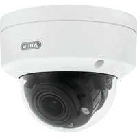
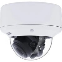
| Outdoor HD-TVI vario dome | Safety information |
| Installation tool | Installation adapter |
| Drilling template |
3. Features and functions
- Transmission via conventional CCTV infrastructure (up to 500 m via RG6 cable)
2.8-12 mm vario lens
1/3 inch CMOS image sensor - IR LEDs for night vision
3D DNR for noise-free images - DWDR function to compensate for image contrasts
- Weatherproof camera housing (IP66)
- On-screen display for camera configuration (control via DVR via coaxial cable)
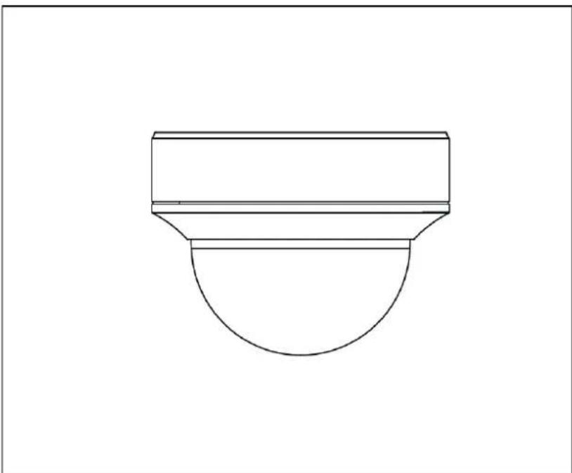
4. Camera description
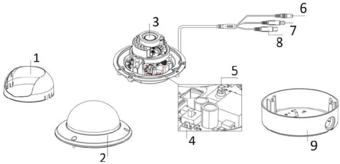
| 1 | Dome cover |
| 2 | Camera dome |
| 3 | Camera module with lens |
| 4 | HDCC71510: Switch between HD-TVI and analogue video output Additional connection for analogue video output (2-pin adapter provided in scope of delivery, labelled 'CVBS') |
| 5 | Joystick for controlling the on-screen display |
| 6 | Power supply connection (5.5 x 2.1 mm, 2-pin connection) |
| 7 | HD-TVI video output (BNC, labelled 'TVI') |
| 8 | Analogue video output (BNC, for service purposes, labelled 'CVBS') |
| 9 | Installation adapter for surface mounting |
5. Mounting/installation
5.1. Mounting the camera

IMPORTANT!
The camera must be disconnected from the power supply during installation.
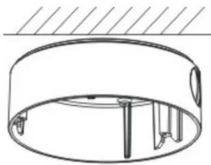
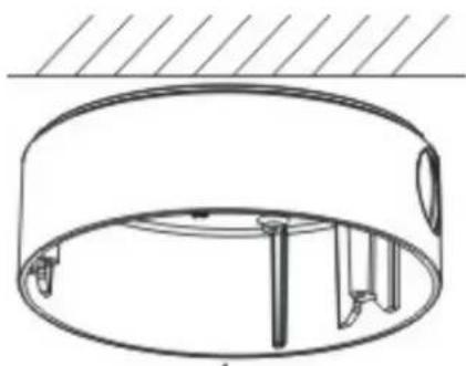
Use the accompanying drilling template for drilling the mounting holes for the installation adapter. An opening is provided on the installation adapter for cabling at the side. A cable gland must be used (M25x1.5) for cabling at the side. Use screw anchors and screws that are appropriate to the surface to fix the installation adapter in place.
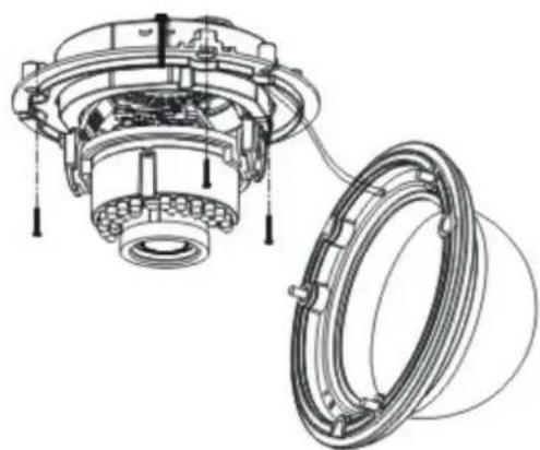
Now remove the camera dome from the camera
module. Use the hexagon wrench provided to do this.

To simplify installation, a retaining rope with eye is provided in the installation adapter to allow the camera module to be suspended.
Now guide the connecting cable through the installation adapter and either into the ceiling or through the side opening.
The connection to the installation cable can be made inside the installation adapter if required.
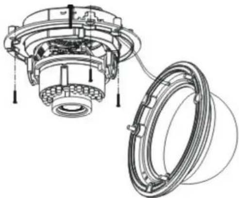
Now insert the camera module into the installation adapter. When doing so, ensure that the guide rail and guide notch of the installation adapter and camera module fit correctly. It is only then that the camera module is in the correct position.

Now retighten the fixing screws of the camera module.
After orienting the camera module, attach the camera cap and camera dome.

Now fix the camera dome in place.
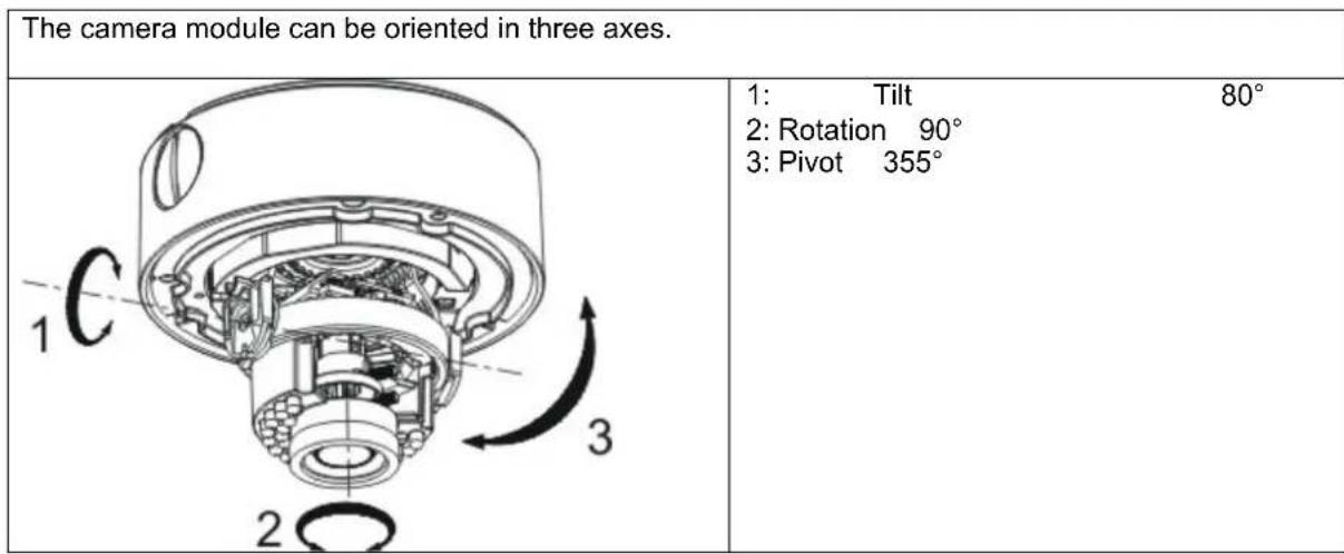
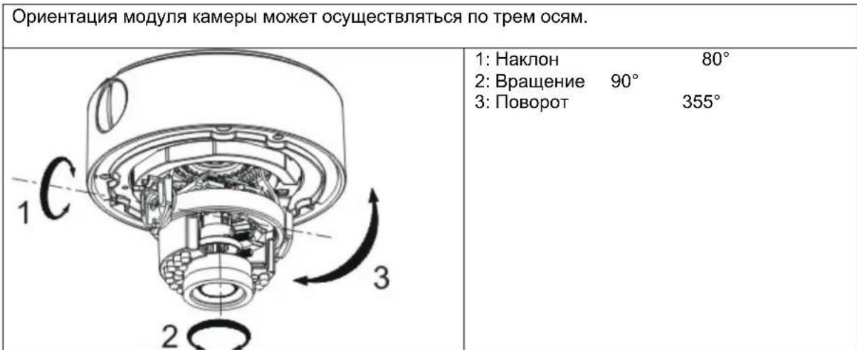
5.2. Orientation of the camera
The IR range is strongly dependent on the environmental conditions. If the area in the camera's field of view reflects poorly or if there are no objects within the max. illumination range, the brightness of the video image at night may be too low. This will result in poor usability of the video image. In addition, when installing the camera it must be ensured that no objects are located in close proximity to the camera's field of view (e.g. roof gutter or wall). These objects can reflect back the IR light, resulting in circular fading on the video image in the opposite direction to the object.
5.3. Power supply

IMPORTANT!
Before starting installation, ensure that the power supply voltage and the rated voltage of the camera are identical.
The cameras require a 12 V DC or 24 V AC power supply. The polarity of the DC voltage supply does not need to be observed!
5.4. Connecting the video cable
In order to transmit the HD-TVI video signal from the camera to a recorder, an RG59 or RG6 type coaxial cable with BNC connector (male) must be connected to the connection labelled 'TVI'. The cable length to the next device must not exceed 500m (RG6) or 300m (RG59).
An RG59 or RG6 type coaxial cable can be connected to the analogue video output (labelled 'CVBS'). The cable length to the next device must not exceed 100m

To ensure optimum quality of the HD-TVI signal transmission, it is important that the cable is neither kinked nor crushed at any point, and that its radius is adequate (min. bending radius 6 cm).
Damage to the cable or porosity as a result of ageing can have a negative impact on the quality of the signal or image (e.g. shadowing around the edges).
5.5. Switching between HD-TVI and analogue video output
A switch on the PCB of the camera module allows you to activate either the HD-TVI output or the analogue video output.
This model does not allow both outputs to be activated at the same time.

After installation and orientation of the intra module, move the switch to the 'TVI' on to activate the HD-TVI output.
6. On-screen display
6.1. Opening the on-screen display
This camera's on-screen display can be opened either using the joystick in the camera or via the ABUS HD-TVI DVR. Please consult the user manual for the ABUS HD-TVI DVR.
6.2. Description of the on-screen display
Pressing the on-screen display control button opens the on-screen display. This on-screen display allows you to adjust a number of detailed settings.
| SETUP | |
| VIDEO STANDARD PAL | |
| LANGUAGE | ENGLISH |
| MAIN MENU ↓ | |
| Function Description | |
| VIDEO STANDARD Video standard setting | PAL: Video output and service monitor output are set to the 50 Hz standard (e.g. 720p50, 1080p50 or PAL)NTSC: Video output and service monitor output are set to the 60 Hz standard (e.g. 720p60, 1080p60 or NTSC) |
| LANGUAGE Setting for the language of the on-screen display | For this camera model, English is currently the only available language. |
| MAIN MENU Advanced camera settings | Press the ENTER button to open the advanced camera settings menu. |
MAIN MENU
| SETUP | |
| AE | ↓ |
| WB | AUTO |
| DAY&NIGHT | SMART↓ |
| VIDEO SETTING ↓ | |
| FUNCTION | ↓ |
| RESET | |
| SAVE&EXIT | SAVE |
AE
This menu item allows you to adjust general exposure settings, e.g. whether the camera should process high contrasts or whether the camera requires special settings for night vision.
| Function Description | |
| BRIGHTNESS (1~10): Picture brightness setting | |
| AE MODE GLOBAL AE: General automatic exposure setting without DWDR functionDWDR: Automatic exposure setting with DWDR function.The DWDR function enables improved display of high image contrasts. The function brightens dark areas of the video image, whilst maintaining the brightness of light areas. | |
| AGC Automatic gain control. As the setting is increased, the video image appears lighter in poor lighting conditions, although the higher the setting the higher the image noise.OFF: DeactivatedLOW: LowMIDDLE: MediumHIGH: High | |
| SENSE UP (0~16): Continuous exposure setting. Longer exposure times for each image make the resulting image lighter. However, the longer the exposure time, the lower the frame rate.0: deactivated2~16: Exposure time increased by a factor of x | |
| RETURN | Return to previous menu screen |
WB
This menu item allows you to adjust the white balance settings.
| Function Description | |
| AUTO Automatic white balance | |
| MANUAL | Manual white balance |
| RGAIN: Gain factor for proportion of red in image | |
| BGAIN: Gain factor for proportion of blue in image | |
| RETURN: Return to previous menu screen |
DAY&NIGHT
This menu item allows you to set the mode for day/night switching.
| Function Description | |
| SMART Automatic activation/deactivation of day mode or night mode. The integrated photo sensor controls the switchover according to the lighting level. INFRARED-LAMP: ON: IR LEDs activated in night mode OFF: IR LEDs deactivated in night mode SMART-IR (0~5): The higher the value, the darker the IR LEDs for very close objects (reduction of IR light intensity). RETURN: Return to previous menu screen | |
| COLOUR The camera stays in colour mode permanently. The infrared cut filter is constantly in front of the lens, and the IR LEDs are constantly off. | |
| B/W The camera stays in black/white mode permanently. The infrared cut filter is constantly separated from the lens. The IR LEDs are switched on and off automatically by the photo sensor. | |
VIDEO SETTING
This menu item allows you to adjust general image settings, such as contrast or video image mirroring.
| Function Description | |
| CONTRAST (1~10): | Image contrast setting |
| SHARPNESS | This function allows image sharpness perception to be adjusted electronically. |
| EDGE (1~10): Change how the edge is displayed in light areas | |
| DETAIL (1~10): Change the sharpness setting of the image | |
| RETURN: Return to previous menu screen | |
| COLOUR GAIN | (1~10): Saturation of the video image |
| 3DNR | Noise reduction function setting. The higher the value set, the more noise will be removed from the video image by the software. |
| OFF: Deactivated | |
| LOW: Low MIDDLE: Medium HIGH: High | |
| MIRROR Mirroring of the video | image OFF: Deactivated HV: Horizontal and vertical image mirroring V: Vertical image mirroring H: Horizontal image mirroring |
| RETURN Return to previous | menu screen |
FUNCTION
| Function Description | |
| DETECTION | Not used |
| The camera's internal motion detection is integrated into the processor platform by default. This camera type does not have an interface (e.g. alarm output) to allow this function to be used. | |
| MASKING Privacy masking settings. A maximum of eight private zones may be freely defined in terms of size and position. | |
| COLOUR: Setting for the colour of all masks | |
| AREA NO. 0~7: Setting for the individual mask | |
| STATUS: ON: Mask active OFF: Mask deactivated | |
| HORIZON. SIZE: Horizontal size of the mask | |
| VERTICAL SIZE: Vertical size of the mask | |
| HORIZON. MOVE: Horizontal starting position of the mask | |
| VERTICAL MOVE: Vertical | |
| ZOOM IN (50/60/70/80/90/100) | |
| Digital zoom function. A value of 100 means than no digital zoom is set. A value of 50 means that 50% of the image, as seen from the centre of the screen, is displayed as the camera image. | |
| RETURN Return to previous menu screen | |
RESET
| Function Description | |
| RESET | Reset all camera settings in the main menu to the factory settings |
SAVE&EXIT
| Function | Description |
| SAVE | Save all settings and exit the on-screen display |
| EXIT | Exit the on-screen display |
7. Maintenance and cleaning
7.1. Maintenance
Regularly check the technical safety of the product, e.g. check the housing for damage.
If it appears to no longer be possible to operate the device safely, stop using the product and secure it to prevent unintentional use.
It is likely that safe operation is no longer possible in the event that:
- the device shows signs of visible damage
- the device no longer works correctly.

Please note:
You do not need to perform any maintenance on the product. There are no components to service and nothing inside the product to check. Never open it.
7.2. Cleaning
Clean the product with a clean, dry cloth. The cloth can be dampened with lukewarm water to remove stubborn dirt.

Do not allow any liquids to enter the device.
Do not use any chemical cleaning products as they could damage the surface of the housing and screen (discolouration).
8. Disposal
Important: EU Directive 2002/96/EC regulates the proper return, treatment and recycling of used electronic devices. This symbol means that in the interest of environmental protection, the device must be disposed of separately from household or industrial waste at the end of its service life in accordance with applicable local legal guidelines. Used devices can be disposed of at official recycling centres in your country. Obey local regulations when disposing of material. Further details on returns (also for non-European countries) can be obtained from your local authority. Separate collection and recycling conserves natural resources and ensures that all the provisions for protecting health and the environment are observed when recycling the product.
9. Technical data
| Model number HDCC71510 | |
| Image sensor 1/3 inch progressive | scan CMOS |
| Camera type Vario dome | |
| Resolution | 720p25, |
| Pixels (effective) 1920 (H) x 1080 (V) | |
| Lens 2.8-12 mm, varifocal lens | |
| Horizontal angle of view 28°-78° | |
| Day/night switching Electromechanical IR cut filter | |
| Minimum illumination (colour) 0.1 Lux | |
| Minimum illumination (B/W) 0.001 Lux (image integration on) | |
| Minimum illumination (IR) 0 Lux | |
| Image integration 2x-16x | |
| Noise reduction 3D DNR | |
| Electronic shutter control | 1/25 s to 1/50,000 s |
| Camera control On-screen display (OSD) | |
| Backlight compensation | DWDR |
| Privacy masking | Eight freely configurable areas |
| Digital zoom | Yes |
| Video system | HD-TVI |
| IR LEDs | 24 |
| IR range | 20 m |
| Smart IR | Yes |
| Connections | Video signal (HD-TVI, BNC), video signal (FBAS, BNC), power supply (DC) |
| Power supply | 12 V DC ± 10%, 24 V AC ± 10% |
| Power consumption | Max. 100 mA (max. 100 W) |
| Operating temperature | -20°C+60°C |
| Humidity | Max. 90% |
| Dimensions (H xØ) | 125 x 143 mm |
| Weight | 950 g |

The IR range is strongly dependent on the environmental conditions. If the area in the camera's field of view reflects poorly or if there are no objects within the max. illumination range, the brightness of the video image at night may be too low. This will result in poor usability of the video image.
In addition, when installing the camera it must be ensured that no objects are located in close proximity to the camera's field of view (e.g. roof gutter or wall). These objects can reflect back the IR light, resulting in circular fading on the video image in the opposite direction to the object.
HDCC71510
5. MoHTax / yCTaHOBka
5.1. MoHTaX KaMepbI

BHIMAHHE! Bo Bpemr moTaxka kamepa doJnxHa 6bItb otKIOUeHa OT cETn 3JIeKTponITaHn.
IcnoB3yIte npnnaHoumca CBepnHbHbIKoNDyKTop dIra CBepeHnHexbIXOTBepCTn Ha yctaHOBOUHOM nepeXODHKe. Pp60koBo npokNaDke Ka6eHa yCTaHOBOUHOMnepeXODHKe Heo6xOdmo NOdTOBNTbOTBepCTne. Pp60koBo npokLaDke Ka6eNAcEduT NcNoB3OBAtB BnHTOBoe Ka6eNbHOeCoedInHeNe (M25x1.5). IcnoB3yIte dIPOCHOBAHnIOxODAuI MIO6eNb INBHTbI Dn3AkrpeHNHeY cTaHOBOUHOro nepeXODHka.
CneDyUOUM WaROM CHIMMTE KYNON C MOyIg KaMepbl.ДЯ 3TOrO NcNoJIb3yIte raeHbI KInOu, BXODAUNB KOMNNEKT NOCTABKN.

YTo6bI o6JIerTuB yCTaHOBky,
yctaHOBOUHbI nepeXoDNHK OCHaIeH TPOcIKOM C NeTJIe IJr NODBeUNBaHN MOnyJKAmePbI.
3aTeM nponyctnte Ka6eJIb Ypee3 yCTaHOBOuHbI INepexoHNK HAnpaBbTe erO JNoB B NOTOnOK, JNoBoYepe3 60KOBoe OTBepCTne.
Pn Heo6xOIMOCn NOKJIIOUeHne K yCTaHOBOCHOMy Ka6eJNO MOXHO OcyIeCTBNTb BHyTpynCTaHOBOOHOro NEpEXOHNka.
Iocne 3TORO BCTaBbTe MoDyNb KaMepbIB yCTaHOBOHbI nepeXoHNK. Pn 3OM CNeIDte, YTO6bl HAnpaBnAIOUa DaYkKa N HApBaBIAIOUa KaHAbKa yCTaHOBOHOrO nepeXoHNka COOTBeTCTBOBAN MOyNIO KaMepbI.ToNkoB B 3OM CNYuae Byet DOCTINHYTo KOPpeKTHOe NINOKeHHe MoDyNIA KaMepbl.

Tenepb 3aTnHte nKcnpuOuine BnHTbMoDyJkaMepebl.
Iocne BbipabHnBaHHaMoDyJMaKApBcYcTaHOBInTe Ko3bpeK n KynoJ KaMepbI.

Tenepb 3aФнксруTe Kynon KaMepbI.
5.2.OpneHTaunKaMepbI

PaInyC DeIcTBnI K n3nyHnB 3HaunTeJIbHO CTeneHn 3aBNCIT OT yCNoBn OKpykaOuSe Cpebl. EcnOkpykaOuOa CpeDa B noNe BVdIMocTn KamepbI o6NaJaET PINOxIMN OtpaKaIOUIMC CBOJCTBAmN, INN B ppeJeIax MAKcIMMaJIbHO DaJIbHOCTN OCBeueHn He HAXoDNTc HNKaKOrO o6bEkTa, TO rPKoCTb BVdeOn3OpaXeHn HOyBo MOKeT 6bItcNIuKOM Hn3KoI. CJeIcTBnem 3tORo MoKeT 6bItb PINOxoE KaueCTBO BVDoeIN3O6paXeHn.
IOMMIO 3TO, npu yctahOBKe kamepbH Heo6xOIMO CJIeHTb, YTO6bI BOKpyr NOJRA BNDMOCTN KAMEpbH IN HENOCpeDCTBEHHOH 6NJ3OCTN OT Hee He HAXOINOCb HNKAKNX oBeKToB (HaNPmep, BOIOCTOCHoro XeJIOBa nn CTHebl). 3TN OBeKtBI MOY T pNBECTN K
OTpaxeHHIO INHpaKpachoro OceueHn. B pe3yIbTaTe Ha BnDEoN3o6paxeHHn MOryt BO3HNKHyTb KpyROBbIE HAnlbIBbI B IpOTNBOnOJXHom 06bekTy HAnpaBNeHHn.
5.3. ΘneKtponntaHne

BHIMAHNE!
Ipeed Hauanom ycTaHOBKn y6eInTeCb TOM, YTO HApJKeHne 3NeKTpOnuTahncooTBetCTByeT HOMHaJIbHOMy HApJKeHIO KamepbI.
Длэгкрпитаня камер Heo6xodmoe Hanpsexe Hcoctabnre 12 B noct. Toka. nnn 24 B nepem. TOKa. He hyxho co6nOdaTb nonpnoctb noaHnapexeHn noctoHHoro TOKa!
5.4. PpoknaKa BndeoKa6eNa
YTo6bI nepeDaT BnDeocnHAn HD-TV1 KaMepbHa pernctpop, HxKHO nOKnIOHTb KoakcnAhbHk Ka6eJIb TnPa RG59 nn RG6 c BNC-pa3bEMOM (tBtpbKObIM) K pa3bemy C hAdnnCbIO "TVI". DInHa Ka6eJIa IpycoeDHeHn K dpyromy yctpoiCTBy He doJXHa ppeBbIaTb 500 MeTPOB (dIra RG6) nn 300 M (nra RG59).
K aHaIorOBomy BnDeObBixOy (HaIINcB "CVBS") MoXHO NODKNIOHTb KOAKCNaHbH KabeNb TnA RG59 nRg6. dInna Ka6eJ Ira npncOeHNHeHn K npYrOmy np6Opy He DoJIkHn PpeBbIaTb 100 MeTpOB.

YTo6bI oBecneuTb onTmamJIbHyU nepeaCy cnHana HD-TV1, Heo6xoJmo n36eraTb nepeNoMa, 3aueMneHnA nn CnNkOM MaIOrO paDnyc npoknaKn Ka6eJa (MNHMJIbHbI paDnyc n3r6a 6 cm).
Ecnn Ka6eIb NOBpeXdeH nn CTan nopncTbIM BCJIeDCTBne npOcecca TapeHn, To 3TO TOKe MOKET Otpa3ntbcra Ha KaueCTBe CnHaJa nn N3o6paXeHn (HanpImep, o6pa3OBaHne TeHei no KpaM).
5.5. NpeeknoueHne HD-TVi n aHaIorObero BndeobbIXoDa
Ha nlaactnHe moDyIa KamepbI HaxOHTcnepeKIOHATeIb, KOtOpBn AKTNBpyET BIXODHD-TV1nn anAHLOROBBI BnDeOBbIXoJ.
Ha 3ToM MoTeN HeBO3MOXHO OndHOBpeMeHHo AKTNbIpObaTb 6a BbIXOa.

YcTaHOBnTe nepeKnOuChaTeNb nocne
yCTaHOBKn N/INN BbIPaBHnBaHnMaOdyJKAmepebl B NOIOKeHne "TVI", YTO6bI 6bl aKTNBnPoBaH BbIXoHD-TVVI.
6. MeHIO 3KpaHa
6.1. OTKpbITb MEHHO 9KpaHa (OSD)
MeHIO 3KpaHa (OSD, On-Screen-Display) 3Toi Kamepe MoKHO OTKpbTb JIN6O C NOMOUsIgKOJCTNka, HaxoJaIeOcR B Kamepe, N60 uepez ABUS HD-TVI DVR. Ia 3ToRo BocNoB3yTeCb INHCTpyKUneI NO 3KcnIpyatau ABUS HD-TVI DVR.
6.2.ОписанеMeHIOЗКраHA(OSD)
Pn Haxatn Ha KnaBnuy npabEnn MeHIO OSD oTKpoetc 3KpaHHoe MeHIO OSD.C nOmoIbIO 3Toro 3KpaHHORo MEHIO MOXHO OcyueCTBNTb DeTaJIbHbIe HAcTpOKn.
| SETUP | |
| VIDEO STANDARD | PAL |
| LANGUAGE | ENGLISH |
| MAIN MENU | |
PaInyc DeIcTBnI NK n3nyeHnB 3HaHTeJIbHOJ CTeneHn 3aBNCIT OT ycIOBNI OKpykaUoSeI cpebl. Ecnn OkpykaUOaJ CpeDa B NOte BnIMOCtN KamepbI OblaJaET PINOxIMN OTPaKaUOUMCBOINCTBAmN, INN B IpeDeJax MaKcImaJIbHOJ DaJIbHOCTN OCBeueHn He HAXODNTcR HnKaKOrO ObEkTa, TO rPKoCTb BnDEoN3OpaXeHn HocbIO MOKeT 6bITb CnIIuKOM Hn3KoI. CneIcTBnEM 3TOrO MOKeT 6bITb PINOxoE KaueCTBO BnDEoN3OpaXeHn.
IOMIMO 3TOrO, npu yctahOBke kamepbI Heo6xOIMcNeHb, YTo6bI BOKpyr NOJRA BVINMOCTN KamepbI IN B HENOCpeDCTBeHHoB 6JIIN3OCTN OT Hee He HaxoINOCb HNKAKNX o6BeKTOB (HaNPmep, BOIOCTOCHoro JKeNo6a INN CTHebl). 3TN O6BeKtBI MOryT pINBECTN K OTpaXeHNIOHnppaKpacHoro OCBeSeHn. B pe3yIbTaTe Ha BInDeon3O6paXeHN MoYr BO3HNKHyTB KpyROBbIE HANlbIBbIB INpOTNBONIOXHom O6BeKTy HAnpaBNeHN.
D Impressum
These operating instructions are published by ABUS Security-Center GmbH & Co.KG, Linker Kreuthweg 5, 86444 Affing, Germany. No reproduction (including translation) is permitted in whole or part e.g. photocopy, microfilming or storage in electronic data processing equipment, without the express written consent of the publisher.
The operating instructions reflect the current technical specifications at the time of print. We reserve the right to change the technical or physical specifications.
Copyright 10/2015 by ABUS Security-Center