SVW300 - Boiler KOSPEL - Free user manual and instructions
Find the device manual for free SVW300 KOSPEL in PDF.
Frequently Asked Questions - SVW300 KOSPEL
User questions about SVW300 KOSPEL
0 question about this device. Answer the ones you know or ask your own.
Ask a new question about this device
Download the instructions for your Boiler in PDF format for free! Find your manual SVW300 - KOSPEL and take your electronic device back in hand. On this page are published all the documents necessary for the use of your device. SVW300 by KOSPEL.
USER MANUAL SVW300 KOSPEL
natural_image
Diagram of a cylindrical container with circular holes and concentric rings (no text or symbols)PL
DE
EN
ES
FR
NL
HR
HU
RO
SV
SVW
Installation and operation manual
Explanation of symbols 23
Assembly and operating instructions 24
Application 24
Construction 25
Installation 29
Start -up 29
How to deal with damage or irregularities 30
Decomissioning 30
Recycling and waste disposal 30
Technical data 31

Read this manual thoroughly before use.
Follow the manual to ensure safe and correct operation of the product.
Keep the manual for reference.

Follow the safety instructions carefully in order to prevent injury and damage.

Danger
This sign warns against danger of injury.
Note
This sign warns against property damage and environmental pollution.
Tip
Text marked with the word Tip contains additional information.

Refer to this manual when operating the product or its controls labelled with this symbol.
Applicable laws and regulations
• National electrical wiring and water plumbing installation codes.
• Statutory occupational hygiene and safety regulations.
• Statutory environmental protection regulations.
• Regulations of professional and insurance associations.
• Prevailing national safety regulations.
- Read and strictly follow this assembly and operating instructions to ensure a long life and reliable buffer tank operation.
- The manufacturer of this buffer tank will not be liable for any damages due to the failure to follow this assembly and operating instructions.
- During all work related to the installation, servicing or maintenance of the device, the principles of health and safety, explosion protection, fire protection and environmental protection must be observed in accordance with the applicable requirements and regulations in the respective country.
- The buffer tank must not be installed in rooms where the temperature may drop below 0^ C.
- The buffer tank installation and initial start-up as well as all hydraulic work must be performed by a qualified installer.
- The heating water must comply with all of the relevant local water quality standard.
- Rated temperature of water in the buffer tank should not exceed 80°C (400l and 500l). In the buffer tank (200l; 300l; 800l; 1000l) should not exceed 95°C.
Application
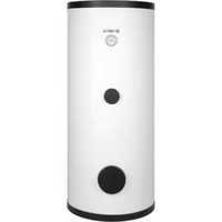
The buffer tanks SV and SVW are devices designed for storing heating water (and/or cooling for 200; 300 liters) in collaboration with heating boilers and heat pumps. Additionally, they serve as a manifold (coupling), hydraulic separator, and heating circuit from the boiler room. The SVW tank has a built-in coil for connecting other heat sources. The buffer tank is made of black steel sheet, raw on the inside and protected on the outside with anti-corrosion paint. The SV and SVW tanks have thermal insulation made depending on the capacity from: 200, 300 liters - PUR foam; 400, 500 liters - styrofoam; 800-1000 liters polyester fleece. The large number of connections allows for various connection options.
The maximum working pressure of buffer tank:
- 0,3 MPa - Buffer tanks of 200 - 1000 litres
The maximum working pressure in the coil:
- 1 MPa - Buffer tanks of 200 - 1000 litres
text_image
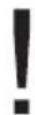
1 2 3 4 5 6 7 8 9 10 11 12 13 14 15 16 17 18 19 20 21 22 23 24 25 26 27 28 29 30 31 32 33 34 35 36 37 38 39 40 41 42 43 44 45 46 47 48 49 50 51 52 53 54 55 56 57 58 59 60 61 62 63 64 65 66 67 68 69 70 71 72 73 74 75 76 77 78 79 80 81 82 83 84 85 86 87 88 89 90 91 92 93 94 95 96 97 98 99 100Buffer tank SV (200l, 300l)
[1] - upper lid
[2] - air vent connector (1/2")
[3] - connection stub (6/4")
[4] - temperature sensor connector (1/2")
[5] - thermal insulation
[6] - feet
[7] - drain connector (1/2")
text_image
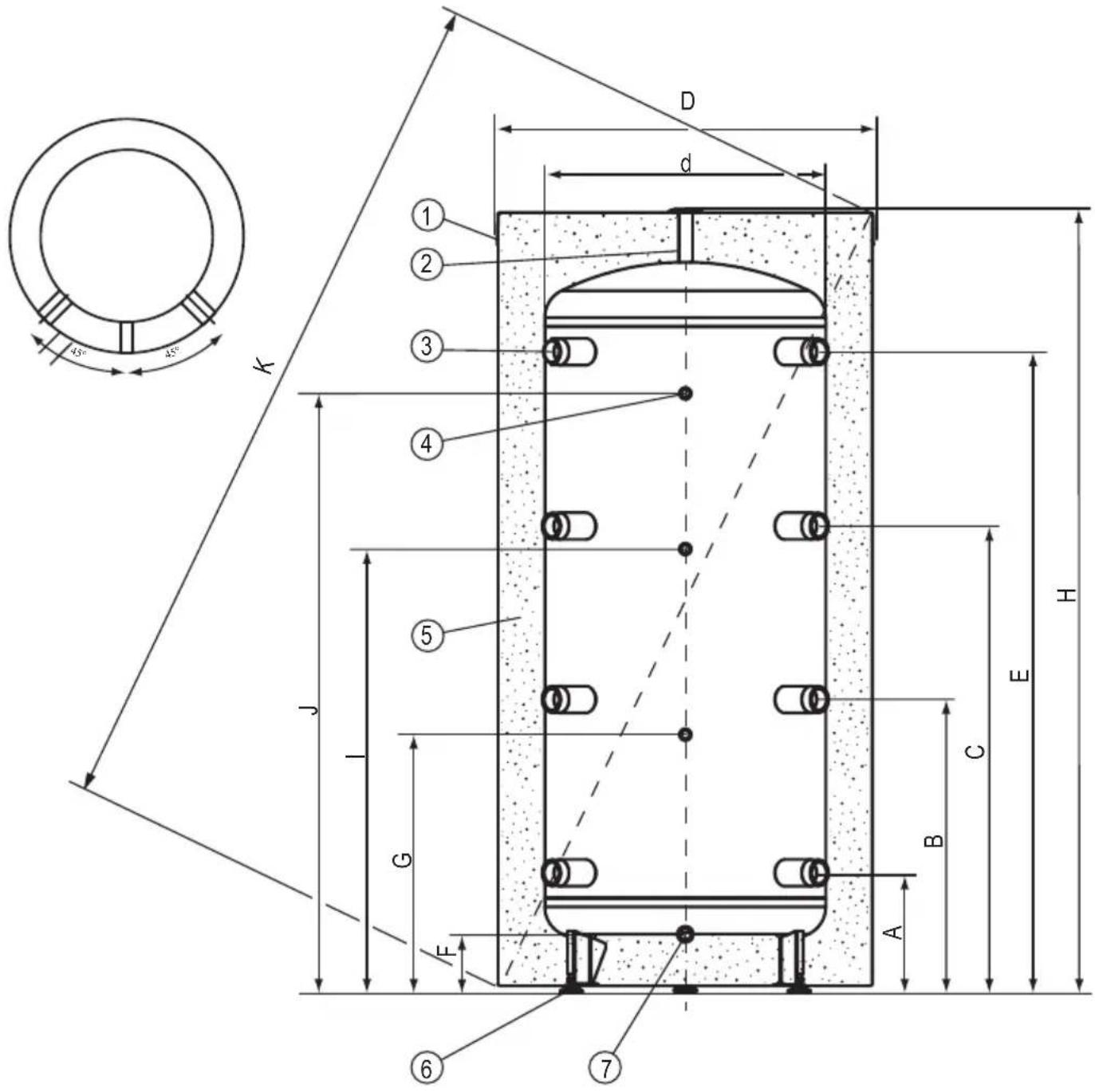
45° 45° D d 1 2 3 4 K J G E 6 7 8 H C B A E d kBuffer tank SV (400l, 500l; 800l; 1000)
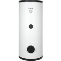
[1] - upper lid
[2] - air vent connector (1/2")
[3] - connection stub (6/4")
[4] - temperature sensor connector (1/2")
[5] - thermal insulation
[6] - feet
[7] - drain connector (1/2")
[8] - lower lid
text_image
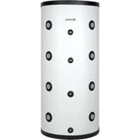
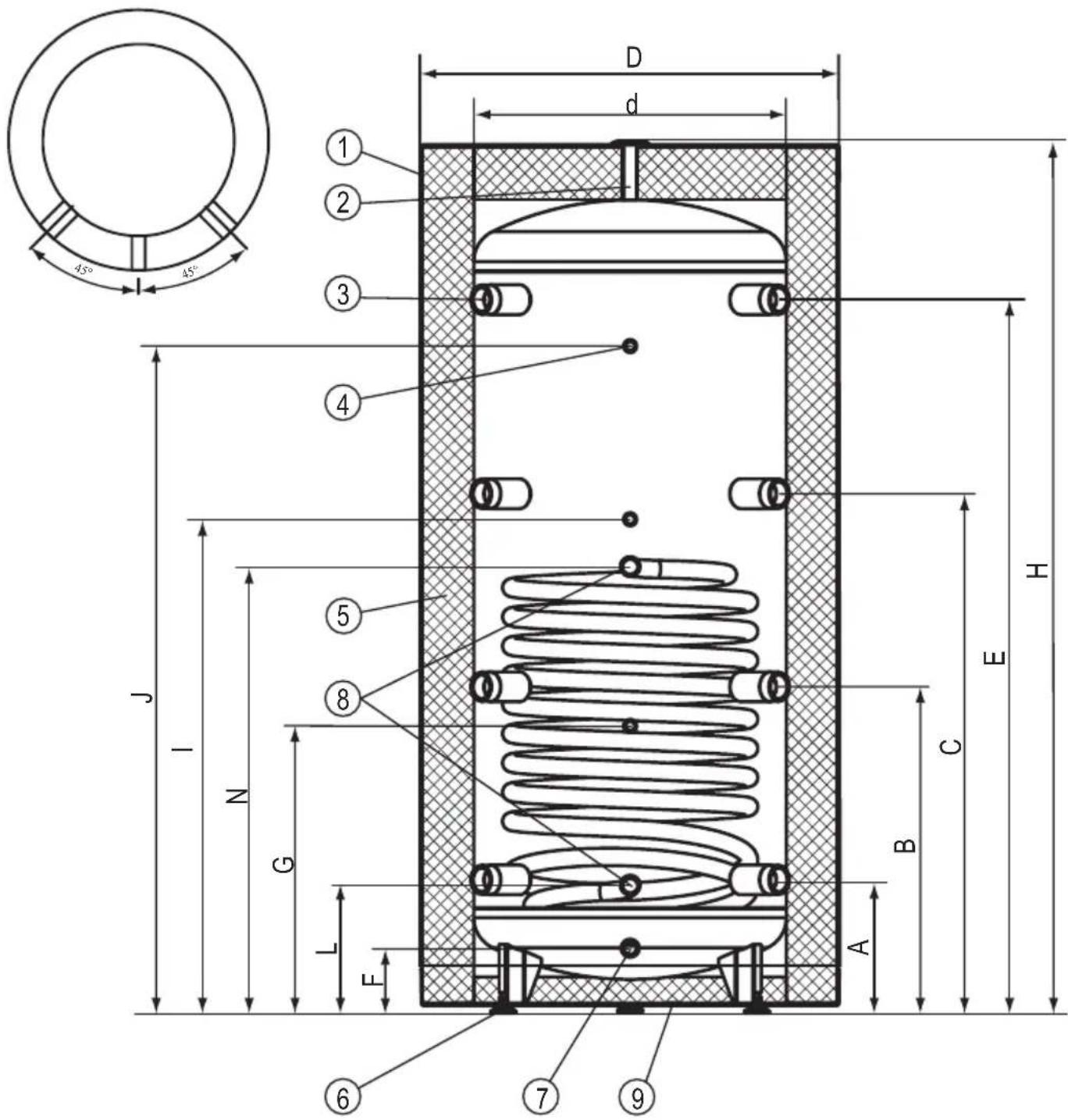
1 2 3 4 5 6 7 8 9 10 11 J N G L E A B C D d H 45° 45°Buffer tank with heating coil SVW (200l, 300l)
[1] - upper lid
[2] - air vent connector (1/2")
[3] - connection stub (6/4")
[4] - temperature sensor connector (1/2")
[5] - thermal insulation
[6] - feet
[7] - drain connector (1/2")
[8] - heating coil connector 1"
text_image
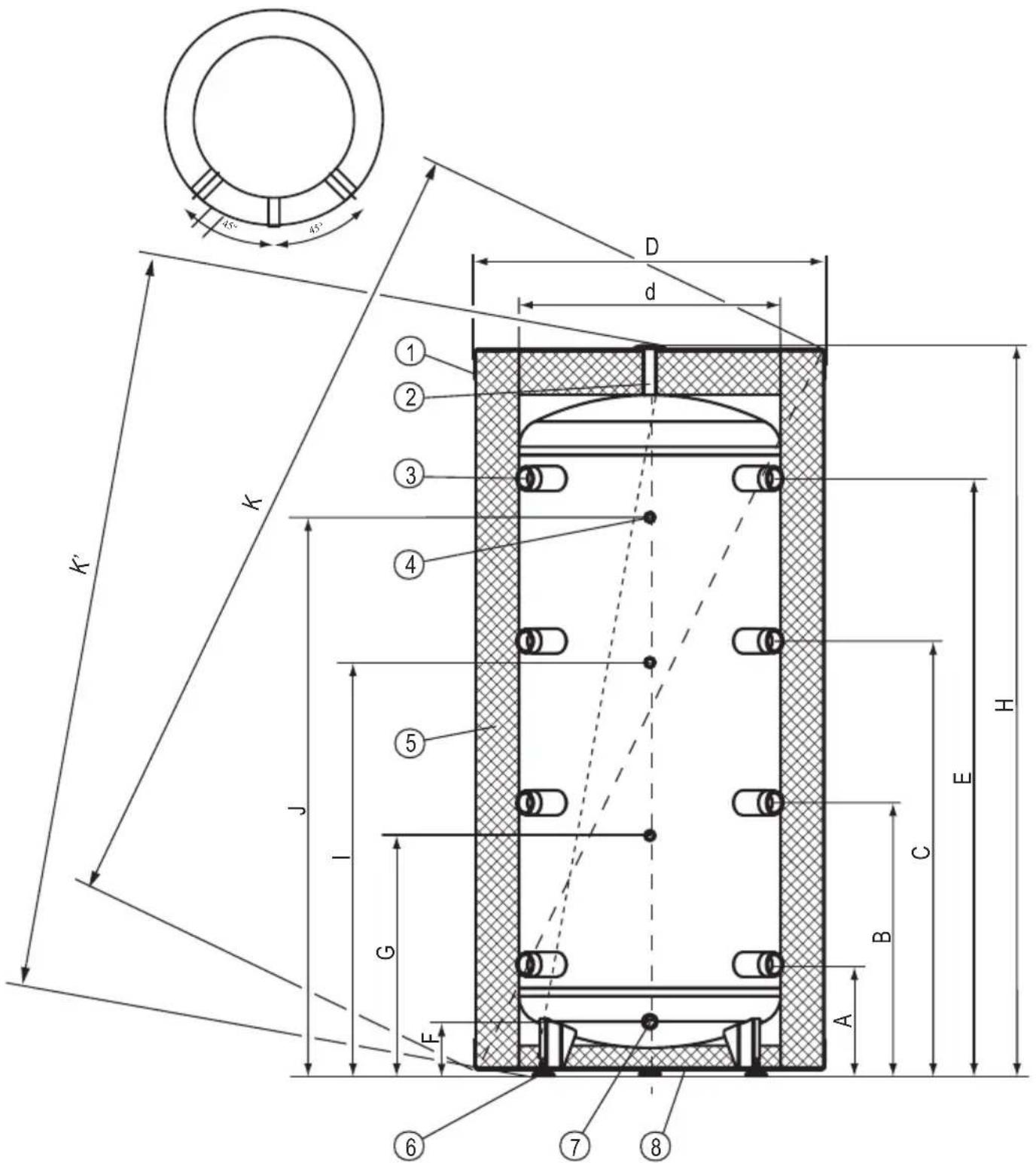
45° 45° 1 2 3 4 D d J I N G L E 6 7 9 A B C E HBuffer tank with heating coil SVW (400l, 500l; 800l; 1000)
[1] - upper lid
[2] - air vent connector (1/2")
[3] - connection stub (6/4")
[4] - temperature sensor connector (1/2")
[5] - thermal insulation
[6] - feet
[7] - drain connector (1/2")
[8] - heating coil connector 1"
[9] - lower lid
Dimensions
| Modell | SV200.1 | SVW200.1 | SV300.2 | SVW300.2 | SV400.1 | SVW400.1 | SV500.1 | SVW500.1 | SV800.1 | SVW800.1 | SV1000.1 | SVW1000.1 | |
| D | 457 5 | 595 692 | 755 854 994 | 4 994 | |||||||||
| 50 600 650 7 | 90 790 | ||||||||||||
| H | 1616 | 1596 1643 1 | 761 1911 224 | 41 | |||||||||
| A | 266 2 | 49 256 261 2 | 294 294 | ||||||||||
| B | 618 6 | 11 626 656 7 | 718 828 | ||||||||||
| C | 970 9 | 73 996 1051 | 1142 1362 | ||||||||||
| E | 1322 | 1338 1368 1 | 446 1566 1895 | ||||||||||
| F | 125m | 26 124 130 1 | 160 160 | ||||||||||
| G | 554 5 | 44 550 629 6 | 691 801 | ||||||||||
| I | 911 9 | 40 947 1064 | 1099 1379 | ||||||||||
| J | 1239 | 1249 1278 1 | 879 1539 1869 | ||||||||||
| K | 1700 1740 1810 1975 2130 2430 | ||||||||||||
| K' | - | - | 1675 | 1800 | 1915 | 2245 | |||||||
| L | - | 256 | - | 239 | - | 246 | - | 251 | - | 293 | - | 293 | |
| N | - | 811 | - | 850 | - | 856 | - | 974 | - | 1182 | - | 1294 | |
Installation
- buffer tank is designed for vertical mounting only (screw feet),
- buffer tank can be installed in the following central heating systems:
- open system, in accordance with legally binding requirements,
- closed system, in accordance with legally binding requirements,
- buffer tank must be mounted in the place and in such a way to avoid room flooding caused be leaking tank or connectors.
Start -up
Check out the pipe connections and make sure that you observe the connection diagrams before start-up.
Check out for water leaks. Check out the safety valve performance in accordance to valve manufacturer's instruction.
| Irregularity Instructions for conduct | |
| Leakage of water from the tank | turn off the CH cut-off valves and contact the service |
| Excessive pressure increase in the tank |
Decomissioning
Used product must not be treated as a household waste. By disposing of this product correctly you will help to prevent potential negative consequences for the environment that could otherwise arise through inappropriate waste handling. For more detailed information about recycling of this product, please contact your local authority waste management service.
Recycling and waste disposal
Removal of product and equipment:
Do not dispose of the product or equipment with household waste. Make sure that the product and all equipment is disposed of properly. Observe all applicable regulations.
| CH buffer tank | SV200.1 | SVW200.1 | SV300.2 | SVW300.2 | SV400.1 | SVW400.1 | SV500.1 | SVW500.1 | SV800.1 | SVW800.1 | SV1000.1 | SVW1000.1 | ||
| Nominal Capacity I 200 300 | 400 5 | 00 800 1000 | ||||||||||||
| Standby Losses W 53 65 87 | 78 12 | 0 121 127 128 | ||||||||||||
| Storage Capacity I 220 219 | 324 3 | 22 399 | 396 49 | 93 490 | 795 79 | 0 942 | 936 | |||||||
| Rated pressure | storage | MPa | 0,3 | |||||||||||
| coil | - | 1 | - | 1 | - | 1 | - | 1 | - | 1 | - | 1 | ||
| Rated temperature | °C 9 | 5 | 80 | 95 | ||||||||||
| Surface area of coil | m^2 | - | 0,75 | - | 1,5 | - | 1,7 | - | 2,25 | - | 3 | - | 3,5 | |
| Coil capacity | dm^3 | - | 4,5 | - | 9,1 | - | 10 | - | 13,7 | - | 22,4 | - | 25,2 | |
| Power of coil | kW | - | 22* | - | 45* | - | 50* | - | 65* | - | 90* | - | 105* | |
| 7** | 14** | 16** | 21** | - | 28* | - | 32** | |||||||
| Weight (empty) | kg | 53 | 69 | 56 | 85 | 86 | 118 | 96 | 131 | 128 | 170 | 150 | 196 | |
.^80 / 10 / 45^ *55 / 10 / 45^ heating water temp./ supply water temp./ domestic water temperature; flow rate of heating water through the coil - 2,5m^3 /h .
Contenido
text_image
K 1 2 3 4 5 J G E H C B A 6 7 d x5° x5° D*80/10/45°C } heating water temp./ supply water temp./ domestic water temperature; flow rate of heating water through the coil **55/10/45°C } - 2,5 m³/h.
Sadržaj
Objašnjenje piktograma 3